EP2479336A1 - Washing machine and pump filter thereof - Google Patents
Washing machine and pump filter thereof Download PDFInfo
- Publication number
- EP2479336A1 EP2479336A1 EP12150418A EP12150418A EP2479336A1 EP 2479336 A1 EP2479336 A1 EP 2479336A1 EP 12150418 A EP12150418 A EP 12150418A EP 12150418 A EP12150418 A EP 12150418A EP 2479336 A1 EP2479336 A1 EP 2479336A1
- Authority
- EP
- European Patent Office
- Prior art keywords
- wash water
- filter
- pump
- washing machine
- filter part
- Prior art date
- Legal status (The legal status is an assumption and is not a legal conclusion. Google has not performed a legal analysis and makes no representation as to the accuracy of the status listed.)
- Granted
Links
Images





Classifications
-
- D—TEXTILES; PAPER
- D06—TREATMENT OF TEXTILES OR THE LIKE; LAUNDERING; FLEXIBLE MATERIALS NOT OTHERWISE PROVIDED FOR
- D06F—LAUNDERING, DRYING, IRONING, PRESSING OR FOLDING TEXTILE ARTICLES
- D06F39/00—Details of washing machines not specific to a single type of machines covered by groups D06F9/00 - D06F27/00
- D06F39/10—Filtering arrangements
-
- D—TEXTILES; PAPER
- D06—TREATMENT OF TEXTILES OR THE LIKE; LAUNDERING; FLEXIBLE MATERIALS NOT OTHERWISE PROVIDED FOR
- D06F—LAUNDERING, DRYING, IRONING, PRESSING OR FOLDING TEXTILE ARTICLES
- D06F35/00—Washing machines, apparatus, or methods not otherwise provided for
- D06F35/002—Washing machines, apparatus, or methods not otherwise provided for using bubbles
-
- D—TEXTILES; PAPER
- D06—TREATMENT OF TEXTILES OR THE LIKE; LAUNDERING; FLEXIBLE MATERIALS NOT OTHERWISE PROVIDED FOR
- D06F—LAUNDERING, DRYING, IRONING, PRESSING OR FOLDING TEXTILE ARTICLES
- D06F39/00—Details of washing machines not specific to a single type of machines covered by groups D06F9/00 - D06F27/00
- D06F39/08—Liquid supply or discharge arrangements
- D06F39/083—Liquid discharge or recirculation arrangements
- D06F39/085—Arrangements or adaptations of pumps
Definitions
- Embodiments of the present disclosure relate to a pump of a washing machine which circulates or drains wash water and a filter which is detachably mounted in the pump.
- a washing machine is an apparatus which washes laundry by rotating a cylindrical drum in which the laundry and wash water are contained. Washing machines are divided into a drum washing machine which washes laundry by tumbling the laundry through rotation of a drum and a pulsator washing machine which washes laundry by water current generated by rotation of a pulsator.
- a washing machine includes a tub to contain wash water, a drum rotatably installed within the tub and provided with spin-drying holes formed on the circumferential surface thereof for spin-drying, and a drive device to drive the drum.
- the washing machine further includes a water supply device to supply wash water into the tub, and a pump to drain the wash water in the tub.
- a pump of the washing machine having such a bubble generator is connected to a drain pipe and a circulation pipe in both directions, and is thus provided with a cylindrical pump filter to filter out foreign substances from wash water.
- a washing machine includes a tub containing wash water, a pump case including an inflow chamber into which the wash water in the tub flows, a circulation pump chamber provided at one side of the inflow chamber to supply wash water to the tub, and a drain pump chamber provided at the other side of the inflow chamber to discharge the wash water to the outside of a main body, and a pump filter installed in the inflow chamber to filter out foreign substances from the wash water, wherein the pump filter includes a first filter part passing wash water flowing into the circulation pump chamber and a second filter part passing wash water flowing into the drain pump chamber, and the first filter part includes a blocking wall preventing the wash water from rectilinearly flowing into the circulation pump chamber and guiding detouring of the wash water.
- the pump filter may have a hollow cylindrical shape.
- the pump filter may further include an inflow hole formed at one end thereof to enable wash water to be introduced into the pump filter through the inflow hole.
- the blocking wall may be formed at the center of the first filter part.
- the first filter part may include a plurality of first collection holes formed at both sides of the blocking wall to filter out foreign substances from the wash water detoured via the blocking wall.
- the second filter part may include a plurality of second collection holes to filter out foreign substances from the wash water.
- the pump filter may further include a direction adjustment groove formed to adjust positions of the first filter part and the second filter part within the inflow chamber.
- the second filter part may include an opening to effectively drain the wash water.
- the second filter part may include a conical filter part protruding inwardly to effectively drain the wash water.
- the pump case may further include a direction adjustment rib protruding to be inserted into the direction adjustment groove of the pump filter.
- the pump filter may further include a head provided with a handle, and the head may be rotatably connected to the first filter part and the second filter part.
- the pump filter may be detachably connected to the inflow chamber of the pump case.
- Bubbles may be generated in wash water in the circulation pump chamber of the pump case and the wash water having the bubbles may be supplied to the tub.
- a washing machine includes a tub containing wash water, a pump case including an inflow chamber into which the wash water in the tub flows, a circulation pump chamber provided at one side of the inflow chamber to generate bubbles in wash water and to supply the wash water having the bubbles to the tub, and a drain pump chamber provided at the other side of the inflow chamber to discharge the wash water to the outside of a main body, and a pump filter detachably installed in the inflow chamber, wherein the pump filter includes a first filter part including a plurality of first collection holes to filter out foreign substances from wash water flowing into the circulation pump chamber and a second filter part including a plurality of second collection holes having a larger size than the plurality of first collection holes to filter out foreign substances from wash water flowing into the drain pump chamber, and a blocking wall guiding detouring of the wash water to prevent accumulation and growth of foreign substances in the pump filter is formed between the plurality of first collection holes of the first filter part.
- a pump filter having a cylindrical shape and connected to a pump case of a washing machine includes an inflow hole formed at one end of the pump filter to enable wash water to be introduced into the pump filter through the inflow hole, a first filter part formed at a part of the circumferential surface of the pump filter to pass the wash water introduced through the inflow hole, and including a blocking wall to change a flow of the wash water and a plurality of first collection holes formed at both sides of the blocking wall to filter out foreign substances from the wash water, and a second filter part formed at the remaining part of the circumferential surface of the pump filter to pass the wash water introduced through the inflow hole, and including a plurality of second collection holes to filter out foreign substances from the wash water.
- the plurality of first collection holes may have a smaller size than the plurality of second collection holes.
- An opening to effectively drain the wash water may be formed at the second filter part.
- a conical filter part protruding inwardly to effectively drain the wash water may be formed at the second filter part.
- FIG. 1 is a cross-sectional view of a washing machine in accordance with one embodiment of the present disclosure.
- a washing machine 1 in accordance with this embodiment of the present disclosure includes a main body 10 forming the external appearance of the washing machine 1, a tub 11 installed within the main body 10 to contain wash water during washing, and a drum 12 rotatably installed within the tub 11 and provided with a plurality of spin-drying holes 15.
- An inlet 13 through which laundry is put into the drum 12 and a door 14 to open and close the inlet 13 are formed on the front surface of the main body 10.
- a water supply device 20 to supply wash water and a detergent supply device 30 to supply detergent are installed at the upper portion of the inside of the main body 10.
- the water supply device 20 includes a water supply valve 21 to control supply of wash water and a water supply pipe 22 connecting the water supply valve 21 to the detergent supply device 30.
- Wash water having passed through the detergent supply device 30 is guided to the inside of the tub 11 through a connection pipe 23.
- a drive motor 41 to rotate the drum 12 is installed on the outer surface of the rear portion of the tub 11, and a drive shaft 42 to transmit drive force of the drive motor 41 to the drum 12 is installed between the drum 12 and the drive motor 41. Further, a bearing housing 43 to rotatably support the drive shaft 42 is installed on a rear plate of the tub 11, and bearings 44 are installed between the bearing housing 43 and the drive shaft 42.
- a pump 90 to pump the wash water contained in the tub 11 is installed at the lower portion of the inside of the main body 10, and a bubble generator (not shown) to generate bubbles is provided within the pump 90.
- the pump 90 is connected to a plurality of connection pipes.
- the plural connection pipes include a first drain pipe 50 connected to a drain hole 17 of the tub 11, a second drain pipe 60 pumping wash water to discharge the wash water to the outside of the main body 10, a circulation pipe 80 connected to the upper surface of the tub 11 to generate bubbles within the wash water to supply the wash water having the bubbles to the inside of the tub 11, and an air supply pipe 70 connected to the upper portion of the tub 11 to supply air to the bubble generator (not shown) within the circulation pipe 80.
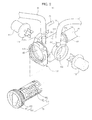
- FIG. 2 is an exploded perspective view of the pump of the washing machine of FIG. 1
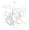
- FIG. 3 is a perspective view of the pump of the washing machine of FIG. 1 in an assembled state.
- the pump 90 includes a pump case 100, and a filter 150 mounted in the pump case 100.
- the pump case 100 includes a circulation pump chamber 123, an inflow chamber 113 and a drain pump chamber 133.
- the circulation pump chamber 123 and the drain pump chamber 133 are opposite each other across the inflow chamber 113.
- the inflow chamber 113 is provided with an inflow port 114 so as to communicate with the first drain pipe 50.
- the wash water in the tub 11 flows into the inflow chamber 113 via the first drain pipe 50 and the inflow port 114.
- the filter 150 is mounted in the inflow chamber 113 and removes foreign substances from the wash water flowing from the tub 11.
- An entrance hole 102 through which the filter 150 enters and exits the inflow chamber 113 is provided at the front portion of the inflow chamber 113, and a screw thread 103 to which the filter 150 is screw-connected is formed on the inner circumferential surface of the entrance hole 102.
- a direction adjustment rib 104 to adjust the direction of the pump filter 150 protrudes from one side of the inner surface of the inflow chamber 113.
- Impellers 121 and 131 to forcibly intake and discharge the wash water in the inflow chamber 113 are respectively installed within the circulation pump chamber 123 and the drain pump chamber 133, and pump motors 122 and 132 are respectively connected to the impellers 121 and 131.
- the respective impellers 121 and 131 are rotated by drive force transmitted from the pump motors 122 and 132, intake the wash water in the inflow chamber 113 in the axial direction, and discharge the wash water in the radial direction.
- a circulation port 124 is formed at the circulation pump chamber 123 so as to communicate with the circulation pipe 80.
- the bubble generator (not shown) generating bubbles is provided within the circulation pipe 80, and an air supply pipe 70 to supply air within the tub 11 to the circulation pipe 80 communicates with the circulation pipe 80.
- the bubble generator (not shown) is of a venturi pipe type formed within a part of the circulation pipe 80.
- the bubble generator (not shown) mixes air, introduced through the air supply pipe 70 using a pressure difference due to pressure lowering caused by a flow of wash water, with wash water, thereby generating bubbles.
- a drain port 134 is formed at the drain pump chamber 133 so as to communicate with the second drain pipe 60 to discharge wash water to the outside of the main body 10.
- the pump filter 150 to filter out foreign substances from wash water is detachably mounted in the pump case 100.
- the pump filter 150 is formed in an approximately hollow cylindrical shape, and includes a head 160 and a body 170, one end of which is connected to the head 160.
- An inflow hole 172 through which wash water is introduced into the pump filter 150 is formed at the other end of the body 170 (with reference to FIG. 6 ).
- the body 170 of the pump filter 150 is accommodated within the inflow chamber 113 of the pump case 100.
- a screw thread 162 enabling the pump filter 150 to be screw-connected to the pump case 100 is formed on the outer circumferential surface of the head 160. Further, a handle 161 gripped by a user to rotate the head 160 is provided on the front surface of the head 160.
- the circumferential surface of the body 170 formed to filter out foreign substances from wash water is divided into a first filter part 180 and a second filter part 190. This will be described later.
- the head 160 and the body 170 are mutually rotatably connected.
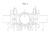
- FIG. 4 is a cross-sectional view taken along the line A-A of FIG. 3
- FIG. 5 is a cross-sectional view taken along the line B-B of FIG. 3
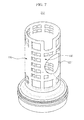
- FIG. 6 is a view illustrating a pump filter in accordance with one embodiment of the present disclosure.
- wash water shown by the arrow A
- introduced through the inflow hole 172 passes through the first filter part 180 and flows into the circulation pump chamber 123, shown by the arrow C, or passes through the second filter part 190 and flows into the drain pump chamber 133, shown by the arrow B.
- the pump filter 150 includes the first filter part 180 formed at one of two sections divided from the circumferential surface of the pump filter 150, and the second filter part 190 formed at the other of the two sections.
- Plural first collection holes 182 and 183 to filter out foreign substances from wash water are formed at both ends of the first filter part 180.
- a blocking wall 181 to change a flow of wash water introduced through the inflow hole 172 is formed at the center of the first filter part 180.
- Plural second collection holes 191, 192 and 193 are formed on the entirety of the second filter part 190, and have a size slightly larger than the first collection holes 182 and 183. Therefore, the second collection holes 191, 192 and 193 may pass relatively larger foreign substances, as compared to the first collection holes 182 and 183.
- Wash water flowing into the circulation pump chamber 123 through the first filter part 180 is blocked by the blocking wall 181 formed at the center of the first filter part 180, and thus does not flow rectilinearly and detours to pass through the first collection holes 182 and 183 (shown by the arrow C).
- Wash water flowing into the circulation pump chamber 123 through the first filter part 180 detours in such a manner and moves, and thus both accumulation and growth of foreign substances at the first collection holes 182 and 183 are reduced.
- the first filter part 180 filtering wash water flowing toward the circulation pump chamber 123 is provided with the blocking wall 181 to detour the wash water
- the second filter part 190 filtering wash water flowing toward the drain pump chamber 133 is provided with the second collection holes 191, 192 and 193 having a relatively large size, and thereby, the pump filter 150 reduces accumulation and growth of foreign substances while effectively filtering out foreign substances from the wash water.
- a direction adjustment groove 173 to determine the position of the blocking wall 81 within the inflow chamber 113 is formed on the pump filter 150.
- the direction adjustment rib 104 protrudes from one side of the inner surface of the inflow chamber 113, as described above, so as to be inserted into the direction adjustment groove 173.
- the direction adjustment groove 173 and the direction adjustment rib 104 are respectively provided at proper positions such that the first filter part 180 of the pump filter 150 faces the circulation pump chamber 123 of the pump case 100.
- the direction adjustment rib 104 of the pump case 100 is inserted into the direction adjustment groove 173 of the pump filter 150 at one position. Then, from this time, the body 170 of the pump filter 150 is fixed under the condition that the first filter part 180 faces the circulation pump chamber 123 of the pump case 100 and the second filter part 190 faces the drain pump chamber 133 of the pump case 100, and only the head 160 of the pump filter 150 is continuously rotated.
- wash water flowing toward the circulation pump chamber 123 passes through the first filter part 180 of the pump filter 150, and wash water flowing toward the drain pump chamber 133 passes through the second filter part 190 of the pump filter 150.
- FIG. 7 is a view illustrating a pump filter in accordance with another embodiment of the present disclosure
- FIG. 8 is a view illustrating a pump filter in accordance with yet another embodiment of the present disclosure
- FIG. 9 is a view illustrating a conical filter part of FIG. 8 .
- wash water flowing toward a drain pump chamber 133 passes through a second filter part 190.
- an opening 251 to effectively drain wash water is formed on the second filter part 190 of a pump filter 250.
- the pump filter 250 filters out foreign substances having a relatively large volume, such as pins and coins, from wash water flowing toward the drain pump chamber 133 and discharged to the outside of the main body 10 and passes foreign substances having a relatively small volume, thereby facilitating drain and suppressing accumulation and growth of the foreign substances, simultaneously.
- a conical filter part 351 protruding inwardly to effectively drain wash water is formed on a second filter part 190 of a pump filter 350.
- Such a conical filter part 351 has an approximately conical shape and includes a first frame part 353 contacting the circumferential surface of the pump filter 350 and a second frame part 352 formed opposite the first frame part 353, as shown in FIG. 9 .
- the first frame part 353 and the second frame part 352 are connected by a plurality of ribs 354, and a plurality of third collection holes 355 are formed between the plurality of ribs 354.
- the pump filter 350 filters out foreign substances having a relatively large volume from wash water flowing toward the drain pump chamber 133 while passing foreign substances having a relatively small volume, thereby increasing filtering effects.
Landscapes
- Engineering & Computer Science (AREA)
- Textile Engineering (AREA)
- Detail Structures Of Washing Machines And Dryers (AREA)
Abstract
Description
- Embodiments of the present disclosure relate to a pump of a washing machine which circulates or drains wash water and a filter which is detachably mounted in the pump.
- In general, a washing machine is an apparatus which washes laundry by rotating a cylindrical drum in which the laundry and wash water are contained. Washing machines are divided into a drum washing machine which washes laundry by tumbling the laundry through rotation of a drum and a pulsator washing machine which washes laundry by water current generated by rotation of a pulsator.
- A washing machine includes a tub to contain wash water, a drum rotatably installed within the tub and provided with spin-drying holes formed on the circumferential surface thereof for spin-drying, and a drive device to drive the drum.
- The washing machine further includes a water supply device to supply wash water into the tub, and a pump to drain the wash water in the tub.
- Recently, a washing machine having a bubble generator to improve washing performance of the washing machine becomes increasingly popular.
- A pump of the washing machine having such a bubble generator is connected to a drain pipe and a circulation pipe in both directions, and is thus provided with a cylindrical pump filter to filter out foreign substances from wash water.
- Therefore, it is an aspect of the present disclosure to provide a filter which reduces accumulation and growth of foreign substances while effectively filtering out the foreign substances from wash water, and a washing machine having the same.
- Additional aspects of the disclosure will be set forth in part in the description which follows and, in part, will be apparent from the description, or may be learned by practice of the disclosure.
- In accordance with one aspect of the present disclosure, a washing machine includes a tub containing wash water, a pump case including an inflow chamber into which the wash water in the tub flows, a circulation pump chamber provided at one side of the inflow chamber to supply wash water to the tub, and a drain pump chamber provided at the other side of the inflow chamber to discharge the wash water to the outside of a main body, and a pump filter installed in the inflow chamber to filter out foreign substances from the wash water, wherein the pump filter includes a first filter part passing wash water flowing into the circulation pump chamber and a second filter part passing wash water flowing into the drain pump chamber, and the first filter part includes a blocking wall preventing the wash water from rectilinearly flowing into the circulation pump chamber and guiding detouring of the wash water.
- The pump filter may have a hollow cylindrical shape.
- The pump filter may further include an inflow hole formed at one end thereof to enable wash water to be introduced into the pump filter through the inflow hole.
- The blocking wall may be formed at the center of the first filter part.
- The first filter part may include a plurality of first collection holes formed at both sides of the blocking wall to filter out foreign substances from the wash water detoured via the blocking wall.
- The second filter part may include a plurality of second collection holes to filter out foreign substances from the wash water.
- The pump filter may further include a direction adjustment groove formed to adjust positions of the first filter part and the second filter part within the inflow chamber.
- The second filter part may include an opening to effectively drain the wash water.
- The second filter part may include a conical filter part protruding inwardly to effectively drain the wash water.
- The pump case may further include a direction adjustment rib protruding to be inserted into the direction adjustment groove of the pump filter.
- The pump filter may further include a head provided with a handle, and the head may be rotatably connected to the first filter part and the second filter part.
- The pump filter may be detachably connected to the inflow chamber of the pump case.
- Bubbles may be generated in wash water in the circulation pump chamber of the pump case and the wash water having the bubbles may be supplied to the tub.
- In accordance with another aspect of the present disclosure, a washing machine includes a tub containing wash water, a pump case including an inflow chamber into which the wash water in the tub flows, a circulation pump chamber provided at one side of the inflow chamber to generate bubbles in wash water and to supply the wash water having the bubbles to the tub, and a drain pump chamber provided at the other side of the inflow chamber to discharge the wash water to the outside of a main body, and a pump filter detachably installed in the inflow chamber, wherein the pump filter includes a first filter part including a plurality of first collection holes to filter out foreign substances from wash water flowing into the circulation pump chamber and a second filter part including a plurality of second collection holes having a larger size than the plurality of first collection holes to filter out foreign substances from wash water flowing into the drain pump chamber, and a blocking wall guiding detouring of the wash water to prevent accumulation and growth of foreign substances in the pump filter is formed between the plurality of first collection holes of the first filter part.
- In accordance with a further aspect of the present disclosure, a pump filter having a cylindrical shape and connected to a pump case of a washing machine includes an inflow hole formed at one end of the pump filter to enable wash water to be introduced into the pump filter through the inflow hole, a first filter part formed at a part of the circumferential surface of the pump filter to pass the wash water introduced through the inflow hole, and including a blocking wall to change a flow of the wash water and a plurality of first collection holes formed at both sides of the blocking wall to filter out foreign substances from the wash water, and a second filter part formed at the remaining part of the circumferential surface of the pump filter to pass the wash water introduced through the inflow hole, and including a plurality of second collection holes to filter out foreign substances from the wash water.
- The plurality of first collection holes may have a smaller size than the plurality of second collection holes.
- An opening to effectively drain the wash water may be formed at the second filter part.
- A conical filter part protruding inwardly to effectively drain the wash water may be formed at the second filter part.
- These and/or other aspects of the disclosure will become apparent and more readily appreciated from the following description of the embodiments, taken in conjunction with the accompanying drawings of which:
-
FIG. 1 is a cross-sectional view of a washing machine in accordance with one embodiment of the present disclosure; -
FIG. 2 is an exploded perspective view of a pump of the washing machine ofFIG. 1 ; -
FIG. 3 is a perspective view of the pump of the washing machine ofFIG. 1 in an assembled state; -
FIG. 4 is a cross-sectional view taken along the line A-A ofFIG. 3 ; -
FIG. 5 is a cross-sectional view taken along the line B-B ofFIG. 3 ; -
FIG. 6 is a view illustrating a pump filter in accordance with one embodiment of the present disclosure; -
FIG. 7 is a view illustrating a pump filter in accordance with another embodiment of the present disclosure; -
FIG. 8 is a view illustrating a pump filter in accordance with yet another embodiment of the present disclosure; and -
FIG. 9 is a view illustrating a conical filter part ofFIG. 8 . - Reference will now be made in detail to the embodiments of the present disclosure, examples of which are illustrated in the accompanying drawings, wherein like reference numerals refer to like elements throughout.
-
FIG. 1 is a cross-sectional view of a washing machine in accordance with one embodiment of the present disclosure. - As shown in
FIG. 1 , awashing machine 1 in accordance with this embodiment of the present disclosure includes amain body 10 forming the external appearance of thewashing machine 1, atub 11 installed within themain body 10 to contain wash water during washing, and adrum 12 rotatably installed within thetub 11 and provided with a plurality of spin-drying holes 15. - An
inlet 13 through which laundry is put into thedrum 12 and adoor 14 to open and close theinlet 13 are formed on the front surface of themain body 10. - A
water supply device 20 to supply wash water and adetergent supply device 30 to supply detergent are installed at the upper portion of the inside of themain body 10. - The
water supply device 20 includes awater supply valve 21 to control supply of wash water and awater supply pipe 22 connecting thewater supply valve 21 to thedetergent supply device 30. - Wash water having passed through the
detergent supply device 30 is guided to the inside of thetub 11 through aconnection pipe 23. - A
drive motor 41 to rotate thedrum 12 is installed on the outer surface of the rear portion of thetub 11, and adrive shaft 42 to transmit drive force of thedrive motor 41 to thedrum 12 is installed between thedrum 12 and thedrive motor 41. Further, abearing housing 43 to rotatably support thedrive shaft 42 is installed on a rear plate of thetub 11, andbearings 44 are installed between thebearing housing 43 and thedrive shaft 42. - A
pump 90 to pump the wash water contained in thetub 11 is installed at the lower portion of the inside of themain body 10, and a bubble generator (not shown) to generate bubbles is provided within thepump 90. - The
pump 90 is connected to a plurality of connection pipes. The plural connection pipes include afirst drain pipe 50 connected to adrain hole 17 of thetub 11, asecond drain pipe 60 pumping wash water to discharge the wash water to the outside of themain body 10, acirculation pipe 80 connected to the upper surface of thetub 11 to generate bubbles within the wash water to supply the wash water having the bubbles to the inside of thetub 11, and anair supply pipe 70 connected to the upper portion of thetub 11 to supply air to the bubble generator (not shown) within thecirculation pipe 80. -
FIG. 2 is an exploded perspective view of the pump of the washing machine ofFIG. 1 , andFIG. 3 is a perspective view of the pump of the washing machine ofFIG. 1 in an assembled state. - As shown in
FIGS. 2 and3 , thepump 90 includes apump case 100, and afilter 150 mounted in thepump case 100. - The
pump case 100 includes acirculation pump chamber 123, aninflow chamber 113 and adrain pump chamber 133. Thecirculation pump chamber 123 and thedrain pump chamber 133 are opposite each other across theinflow chamber 113. - The
inflow chamber 113 is provided with aninflow port 114 so as to communicate with thefirst drain pipe 50. During operation of thepump 90, the wash water in thetub 11 flows into theinflow chamber 113 via thefirst drain pipe 50 and theinflow port 114. - The
filter 150 is mounted in theinflow chamber 113 and removes foreign substances from the wash water flowing from thetub 11. - An
entrance hole 102 through which thefilter 150 enters and exits theinflow chamber 113 is provided at the front portion of theinflow chamber 113, and ascrew thread 103 to which thefilter 150 is screw-connected is formed on the inner circumferential surface of theentrance hole 102. - A
direction adjustment rib 104 to adjust the direction of thepump filter 150, which will be described later, protrudes from one side of the inner surface of theinflow chamber 113. -
Impellers inflow chamber 113 are respectively installed within thecirculation pump chamber 123 and thedrain pump chamber 133, and pumpmotors impellers respective impellers pump motors inflow chamber 113 in the axial direction, and discharge the wash water in the radial direction. - A
circulation port 124 is formed at thecirculation pump chamber 123 so as to communicate with thecirculation pipe 80. - The bubble generator (not shown) generating bubbles is provided within the
circulation pipe 80, and anair supply pipe 70 to supply air within thetub 11 to thecirculation pipe 80 communicates with thecirculation pipe 80. - The bubble generator (not shown) is of a venturi pipe type formed within a part of the
circulation pipe 80. The bubble generator (not shown) mixes air, introduced through theair supply pipe 70 using a pressure difference due to pressure lowering caused by a flow of wash water, with wash water, thereby generating bubbles. - Further, a
drain port 134 is formed at thedrain pump chamber 133 so as to communicate with thesecond drain pipe 60 to discharge wash water to the outside of themain body 10. - The
pump filter 150 to filter out foreign substances from wash water is detachably mounted in thepump case 100. - The
pump filter 150 is formed in an approximately hollow cylindrical shape, and includes ahead 160 and abody 170, one end of which is connected to thehead 160. Aninflow hole 172 through which wash water is introduced into thepump filter 150 is formed at the other end of the body 170 (with reference toFIG. 6 ). - When the
pump filter 150 is mounted in thepump case 100, thebody 170 of thepump filter 150 is accommodated within theinflow chamber 113 of thepump case 100. - A
screw thread 162 enabling thepump filter 150 to be screw-connected to thepump case 100 is formed on the outer circumferential surface of thehead 160. Further, ahandle 161 gripped by a user to rotate thehead 160 is provided on the front surface of thehead 160. - The circumferential surface of the
body 170 formed to filter out foreign substances from wash water is divided into afirst filter part 180 and asecond filter part 190. This will be described later. - Further, the
head 160 and thebody 170 are mutually rotatably connected. -
FIG. 4 is a cross-sectional view taken along the line A-A ofFIG. 3 ,FIG. 5 is a cross-sectional view taken along the line B-B ofFIG. 3 , andFIG. 6 is a view illustrating a pump filter in accordance with one embodiment of the present disclosure. - As shown in
FIG. 5 , wash water, shown by the arrow A, introduced through theinflow hole 172 passes through thefirst filter part 180 and flows into thecirculation pump chamber 123, shown by the arrow C, or passes through thesecond filter part 190 and flows into thedrain pump chamber 133, shown by the arrow B. - Further, as shown in
FIG, 6 thepump filter 150 includes thefirst filter part 180 formed at one of two sections divided from the circumferential surface of thepump filter 150, and thesecond filter part 190 formed at the other of the two sections. - Plural first collection holes 182 and 183 to filter out foreign substances from wash water are formed at both ends of the
first filter part 180. A blockingwall 181 to change a flow of wash water introduced through theinflow hole 172 is formed at the center of thefirst filter part 180. - Plural second collection holes 191, 192 and 193 are formed on the entirety of the
second filter part 190, and have a size slightly larger than the first collection holes 182 and 183. Therefore, the second collection holes 191, 192 and 193 may pass relatively larger foreign substances, as compared to the first collection holes 182 and 183. - Wash water flowing into the
circulation pump chamber 123 through thefirst filter part 180 is blocked by the blockingwall 181 formed at the center of thefirst filter part 180, and thus does not flow rectilinearly and detours to pass through the first collection holes 182 and 183 (shown by the arrow C). - Wash water flowing into the
circulation pump chamber 123 through thefirst filter part 180 detours in such a manner and moves, and thus both accumulation and growth of foreign substances at the first collection holes 182 and 183 are reduced. - In accordance with the embodiment of the present disclosure, the
first filter part 180 filtering wash water flowing toward thecirculation pump chamber 123 is provided with the blockingwall 181 to detour the wash water, and thesecond filter part 190 filtering wash water flowing toward thedrain pump chamber 133 is provided with the second collection holes 191, 192 and 193 having a relatively large size, and thereby, thepump filter 150 reduces accumulation and growth of foreign substances while effectively filtering out foreign substances from the wash water. - As shown in
FIG. 6 , adirection adjustment groove 173 to determine the position of the blocking wall 81 within theinflow chamber 113 is formed on thepump filter 150. - The
direction adjustment rib 104 protrudes from one side of the inner surface of theinflow chamber 113, as described above, so as to be inserted into thedirection adjustment groove 173. - The
direction adjustment groove 173 and thedirection adjustment rib 104 are respectively provided at proper positions such that thefirst filter part 180 of thepump filter 150 faces thecirculation pump chamber 123 of thepump case 100. - When the
pump filter 150 enters theinflow chamber 113 of thepump case 100 and thehead 160 of thefilter 150 is rotated, thedirection adjustment rib 104 of thepump case 100 is inserted into thedirection adjustment groove 173 of thepump filter 150 at one position. Then, from this time, thebody 170 of thepump filter 150 is fixed under the condition that thefirst filter part 180 faces thecirculation pump chamber 123 of thepump case 100 and thesecond filter part 190 faces thedrain pump chamber 133 of thepump case 100, and only thehead 160 of thepump filter 150 is continuously rotated. - Through such a configuration, wash water flowing toward the
circulation pump chamber 123 passes through thefirst filter part 180 of thepump filter 150, and wash water flowing toward thedrain pump chamber 133 passes through thesecond filter part 190 of thepump filter 150. -
FIG. 7 is a view illustrating a pump filter in accordance with another embodiment of the present disclosure,FIG. 8 is a view illustrating a pump filter in accordance with yet another embodiment of the present disclosure, andFIG. 9 is a view illustrating a conical filter part ofFIG. 8 . - In the same manner as the earlier embodiment, wash water flowing toward a
drain pump chamber 133 passes through asecond filter part 190. - As shown in
FIG. 7 , anopening 251 to effectively drain wash water is formed on thesecond filter part 190 of apump filter 250. Through such a configuration, thepump filter 250 filters out foreign substances having a relatively large volume, such as pins and coins, from wash water flowing toward thedrain pump chamber 133 and discharged to the outside of themain body 10 and passes foreign substances having a relatively small volume, thereby facilitating drain and suppressing accumulation and growth of the foreign substances, simultaneously. - Further, as shown in
FIG. 8 , aconical filter part 351 protruding inwardly to effectively drain wash water is formed on asecond filter part 190 of apump filter 350. - Such a
conical filter part 351 has an approximately conical shape and includes afirst frame part 353 contacting the circumferential surface of thepump filter 350 and asecond frame part 352 formed opposite thefirst frame part 353, as shown inFIG. 9 . Thefirst frame part 353 and thesecond frame part 352 are connected by a plurality ofribs 354, and a plurality of third collection holes 355 are formed between the plurality ofribs 354. - Through such a configuration, the
pump filter 350 filters out foreign substances having a relatively large volume from wash water flowing toward thedrain pump chamber 133 while passing foreign substances having a relatively small volume, thereby increasing filtering effects. - Although a few embodiments of the present disclosure have been shown and described, it would be appreciated by those skilled in the art that changes may be made in these embodiments without departing from the principles and spirit of the invention, the scope of which is defined in the claims and their equivalents.
Claims (13)
- A washing machine comprising:a tub containing wash water;a pump case including an inflow chamber into which the wash water in the tub flows, a circulation pump chamber provided at one side of the inflow chamber to supply wash water to the tub, and a drain pump chamber provided at the other side of the inflow chamber to discharge the wash water to the outside of a main body; anda pump filter installed in the inflow chamber to filter out foreign substances from the wash water, wherein:the pump filter includes a first filter part passing wash water flowing into the circulation pump chamber and a second filter part passing wash water flowing into the drain pump chamber; andthe first filter part includes a blocking wall preventing the wash water from rectilinearly flowing into the circulation pump chamber and guiding detouring of the wash water.
- The washing machine according to claim 1, wherein the pump filter has a hollow cylindrical shape.
- The washing machine according to claim 1, wherein the pump filter further includes an inflow hole formed at one end thereof to enable wash water to be introduced into the pump filter through the inflow hole.
- The washing machine according to claim 1, wherein the blocking wall is formed at the center of the first filter part.
- The washing machine according to claim 1, wherein the first filter part includes a plurality of first collection holes formed at both sides of the blocking wall of the first filter part to filter out foreign substances from the wash water detoured via the blocking wall.
- The washing machine according to claim 1, wherein the second filter part includes a plurality of second collection holes to filter out foreign substances from the wash water.
- The washing machine according to claim 1, wherein the pump filter further includes a direction adjustment groove formed to adjust positions of the first filter part and the second filter part within the inflow chamber.
- The washing machine according to claim 1, wherein the second filter part includes an opening to effectively drain the wash water.
- The washing machine according to claim 1, wherein the second filter part includes a cone-type filter part protruding inwardly to effectively drain the wash water.
- The washing machine according to claim 7, wherein the pump case further includes a direction adjustment rib protruding to be inserted into the direction adjustment groove of the pump filter.
- The washing machine according to claim 1, wherein:the pump filter further includes a head provided with a handle; andthe head is rotatably connected to the first filter part and the second filter part.
- The washing machine according to claim 1, wherein the pump filter is detachably connected to the inflow chamber of the pump case.
- The washing machine according to claim 1, wherein bubbles are generated in wash water in the circulation pump chamber of the pump case and the wash water having the bubbles is supplied to the tub.
Priority Applications (1)
| Application Number | Priority Date | Filing Date | Title |
|---|---|---|---|
| EP14001952.2A EP2792783B1 (en) | 2011-01-21 | 2012-01-09 | Washing machine and pump filter thereof |
Applications Claiming Priority (1)
| Application Number | Priority Date | Filing Date | Title |
|---|---|---|---|
| KR1020110006210A KR101375717B1 (en) | 2011-01-21 | 2011-01-21 | Washing machine and pump filter thereof |
Related Child Applications (2)
| Application Number | Title | Priority Date | Filing Date |
|---|---|---|---|
| EP14001952.2A Division EP2792783B1 (en) | 2011-01-21 | 2012-01-09 | Washing machine and pump filter thereof |
| EP14001952.2A Division-Into EP2792783B1 (en) | 2011-01-21 | 2012-01-09 | Washing machine and pump filter thereof |
Publications (2)
| Publication Number | Publication Date |
|---|---|
| EP2479336A1 true EP2479336A1 (en) | 2012-07-25 |
| EP2479336B1 EP2479336B1 (en) | 2014-07-23 |
Family
ID=45445937
Family Applications (2)
| Application Number | Title | Priority Date | Filing Date |
|---|---|---|---|
| EP12150418.7A Active EP2479336B1 (en) | 2011-01-21 | 2012-01-09 | Washing machine and pump filter thereof |
| EP14001952.2A Active EP2792783B1 (en) | 2011-01-21 | 2012-01-09 | Washing machine and pump filter thereof |
Family Applications After (1)
| Application Number | Title | Priority Date | Filing Date |
|---|---|---|---|
| EP14001952.2A Active EP2792783B1 (en) | 2011-01-21 | 2012-01-09 | Washing machine and pump filter thereof |
Country Status (4)
| Country | Link |
|---|---|
| US (1) | US20120186306A1 (en) |
| EP (2) | EP2479336B1 (en) |
| KR (1) | KR101375717B1 (en) |
| CN (1) | CN202559120U (en) |
Cited By (6)
| Publication number | Priority date | Publication date | Assignee | Title |
|---|---|---|---|---|
| WO2017137176A1 (en) * | 2016-02-10 | 2017-08-17 | BSH Hausgeräte GmbH | Laundry care appliance having a detergent solution pump |
| WO2017148617A1 (en) * | 2016-02-29 | 2017-09-08 | BSH Hausgeräte GmbH | Laundry appliance having a pump and method |
| WO2018007147A1 (en) * | 2016-07-08 | 2018-01-11 | BSH Hausgeräte GmbH | Household appliance having a pump filter |
| WO2018086931A1 (en) * | 2016-11-08 | 2018-05-17 | Arcelik Anonim Sirketi | Drain pump assembly for a washing machine and operating method |
| EP3428338A4 (en) * | 2016-03-08 | 2019-08-14 | LG Electronics Inc. -1- | LAUNDRY PROCESSING APPARATUS AND METHOD OF CONTROLLING THE SAME |
| EP3730688A4 (en) * | 2017-12-22 | 2021-08-04 | Qingdao Jiaonan Haier Washing Machine Co., Ltd. | WASHING MACHINE CIRCULATION AND FILTRATION DEVICE, AND WASHING MACHINE |
Families Citing this family (37)
| Publication number | Priority date | Publication date | Assignee | Title |
|---|---|---|---|---|
| US9758918B2 (en) * | 2012-09-28 | 2017-09-12 | Dongbu Daewoo Electronics Corporation | Washing machine |
| KR101526702B1 (en) * | 2013-11-11 | 2015-06-05 | 동부대우전자 주식회사 | Drainage device for Wall washer |
| CN104928893B (en) * | 2014-03-17 | 2019-06-28 | 博西华电器(江苏)有限公司 | Discharge filtering device and household electrical appliance |
| CN105624989B (en) | 2014-11-27 | 2019-08-13 | 博西华电器(江苏)有限公司 | Circulating drainage devices and household appliances |
| KR102350317B1 (en) * | 2014-12-01 | 2022-01-14 | 삼성전자주식회사 | Washing machine |
| CN105714522B (en) * | 2014-12-02 | 2019-09-20 | 博西华电器(江苏)有限公司 | Recycle drainage arrangement and household electrical appliance |
| KR101716704B1 (en) | 2015-09-17 | 2017-03-16 | 두얼메카닉스 주식회사 | Bubble Generating Device for Washing Machine |
| KR102466659B1 (en) * | 2015-10-07 | 2022-11-11 | 엘지전자 주식회사 | Laundry treating apparatus |
| CN105297336B (en) * | 2015-11-12 | 2018-06-19 | 无锡小天鹅通用电器有限公司 | Washing machine |
| DE102016201969A1 (en) * | 2016-02-10 | 2017-08-10 | BSH Hausgeräte GmbH | Laundry care device with a sealing element |
| DE102016201975B3 (en) * | 2016-02-10 | 2017-03-02 | BSH Hausgeräte GmbH | Laundry care unit with a pump |
| DE102016202006A1 (en) * | 2016-02-10 | 2017-08-10 | BSH Hausgeräte GmbH | Laundry care device with a drain pump |
| KR20170095694A (en) * | 2016-02-15 | 2017-08-23 | 동부대우전자 주식회사 | Washing machine |
| KR102489664B1 (en) * | 2016-02-16 | 2023-01-18 | 주식회사 위니아전자 | Washing machine |
| CN105839362B (en) * | 2016-05-19 | 2019-01-25 | 无锡小天鹅股份有限公司 | Washing machine |
| CN106283537B (en) * | 2016-08-30 | 2019-12-17 | 无锡小天鹅电器有限公司 | Washing machine |
| CN106222961A (en) * | 2016-08-30 | 2016-12-14 | 无锡小天鹅股份有限公司 | Washing machine |
| CN106544831B (en) * | 2016-09-27 | 2022-04-22 | 无锡小天鹅电器有限公司 | Washing machine |
| CN106758020B (en) * | 2016-11-30 | 2023-07-14 | 无锡小天鹅电器有限公司 | A washing machine that is used for washing machine's drainage subassembly and has it |
| CN108118496A (en) * | 2016-11-30 | 2018-06-05 | 青岛海尔洗衣机有限公司 | Drain valve structure and washing machine capable of washing |
| CN106939499B (en) * | 2017-04-10 | 2021-12-17 | 青岛海尔洗涤电器有限公司 | Double-end pump shell structure and washing machine |
| CN107035728B (en) * | 2017-04-10 | 2020-09-29 | 青岛海尔滚筒洗衣机有限公司 | A kind of filter element for double-head pump and double-head pump |
| CN107100900B (en) * | 2017-04-10 | 2020-12-08 | 青岛海尔洗涤电器有限公司 | A double-head pump and washing machine using the double-head pump |
| CN110952265A (en) * | 2018-09-25 | 2020-04-03 | 青岛海尔智能技术研发有限公司 | Washing machine and control method thereof |
| US11319659B2 (en) | 2018-12-28 | 2022-05-03 | Whirlpool Corporation | Button trap and sieve for a laundry appliance |
| KR102179793B1 (en) | 2019-03-27 | 2020-11-17 | 이화여자대학교 산학협력단 | Appratus for filtering drainage of washing machine |
| KR102931805B1 (en) * | 2020-04-29 | 2026-03-04 | 엘지전자 주식회사 | Garment processing equipment |
| EP4190964B1 (en) | 2021-01-15 | 2026-04-22 | Samsung Electronics Co., Ltd. | Filter device |
| DE102021202010A1 (en) | 2021-03-03 | 2022-09-08 | BSH Hausgeräte GmbH | Washing machine with pump-over system and method for its operation |
| JP2022167547A (en) * | 2021-04-23 | 2022-11-04 | 青島海爾洗衣机有限公司 | washing machine |
| EP4357516A4 (en) | 2021-12-31 | 2024-11-27 | Samsung Electronics Co., Ltd. | WASHING MACHINE AND APPARATUS FOR TREATING CLOTHES |
| JP7825520B2 (en) * | 2022-06-21 | 2026-03-06 | シャープ株式会社 | Filter components, washing machines |
| WO2024034795A1 (en) * | 2022-08-09 | 2024-02-15 | 삼성전자주식회사 | Filter device, and clothes treatment apparatus having filter device |
| US12427453B2 (en) * | 2022-11-25 | 2025-09-30 | Samsung Electronics Co., Ltd. | Microplastic filter for washing machines or other appliances |
| KR102880798B1 (en) * | 2022-12-09 | 2025-11-04 | 주식회사 마이크로필터 | Filter assembly and wasing machine including the same |
| JP2025150762A (en) * | 2024-03-27 | 2025-10-09 | パナソニックIpマネジメント株式会社 | Drum washing machine |
| KR20250173868A (en) * | 2024-06-04 | 2025-12-11 | 엘지전자 주식회사 | Filter assembly and laundry treatment apparatus including the same |
Citations (8)
| Publication number | Priority date | Publication date | Assignee | Title |
|---|---|---|---|---|
| EP0140911A1 (en) * | 1983-03-24 | 1985-05-15 | MUNNECKE, Gustav-Adolf | Slope harvester-thresher |
| DE29712762U1 (en) * | 1996-07-19 | 1998-02-26 | PLASET S.r.l., Moncalieri | Inlet filter for a liquid pump, especially for washing machines |
| DE10046349A1 (en) * | 2000-09-19 | 2002-03-28 | Bsh Bosch Siemens Hausgeraete | Domestic electrical appliance e.g. washing machine or dishwasher has recycled water passed through filter at entry of circulation pump in reverse direction for removal of trapped particles |
| JP2006255318A (en) * | 2005-03-18 | 2006-09-28 | Sharp Corp | Washing machine |
| JP2007181560A (en) * | 2006-01-06 | 2007-07-19 | Sanyo Electric Co Ltd | Washing machine |
| KR20080093493A (en) * | 2007-04-17 | 2008-10-22 | 삼성전자주식회사 | washer |
| KR20090006393A (en) * | 2007-07-11 | 2009-01-15 | 삼성전자주식회사 | washer |
| EP2216437A1 (en) * | 2007-11-29 | 2010-08-11 | SANYO Electric Co., Ltd. | Washing machine |
Family Cites Families (6)
| Publication number | Priority date | Publication date | Assignee | Title |
|---|---|---|---|---|
| KR200149370Y1 (en) * | 1995-03-31 | 1999-06-15 | 전주범 | The nap collect filter apparatus of a washing machine |
| KR970039312U (en) * | 1995-12-18 | 1997-07-29 | Drain pump of washing machine | |
| US6402962B1 (en) * | 2000-07-26 | 2002-06-11 | Maytag Corporation | Self-cleaning filter with bypass |
| US7406843B2 (en) * | 2002-05-08 | 2008-08-05 | Whirlpool Corporation | Remote sump with film heater and auto purge |
| KR20040046954A (en) * | 2002-11-28 | 2004-06-05 | 엘지전자 주식회사 | The structure of lint filter in washer |
| KR101287532B1 (en) * | 2007-04-11 | 2013-07-18 | 삼성전자주식회사 | Drum type washing machine |
-
2011
- 2011-01-21 KR KR1020110006210A patent/KR101375717B1/en active Active
-
2012
- 2012-01-09 EP EP12150418.7A patent/EP2479336B1/en active Active
- 2012-01-09 EP EP14001952.2A patent/EP2792783B1/en active Active
- 2012-01-19 CN CN2012200316918U patent/CN202559120U/en not_active Expired - Lifetime
- 2012-01-19 US US13/353,495 patent/US20120186306A1/en not_active Abandoned
Patent Citations (8)
| Publication number | Priority date | Publication date | Assignee | Title |
|---|---|---|---|---|
| EP0140911A1 (en) * | 1983-03-24 | 1985-05-15 | MUNNECKE, Gustav-Adolf | Slope harvester-thresher |
| DE29712762U1 (en) * | 1996-07-19 | 1998-02-26 | PLASET S.r.l., Moncalieri | Inlet filter for a liquid pump, especially for washing machines |
| DE10046349A1 (en) * | 2000-09-19 | 2002-03-28 | Bsh Bosch Siemens Hausgeraete | Domestic electrical appliance e.g. washing machine or dishwasher has recycled water passed through filter at entry of circulation pump in reverse direction for removal of trapped particles |
| JP2006255318A (en) * | 2005-03-18 | 2006-09-28 | Sharp Corp | Washing machine |
| JP2007181560A (en) * | 2006-01-06 | 2007-07-19 | Sanyo Electric Co Ltd | Washing machine |
| KR20080093493A (en) * | 2007-04-17 | 2008-10-22 | 삼성전자주식회사 | washer |
| KR20090006393A (en) * | 2007-07-11 | 2009-01-15 | 삼성전자주식회사 | washer |
| EP2216437A1 (en) * | 2007-11-29 | 2010-08-11 | SANYO Electric Co., Ltd. | Washing machine |
Cited By (8)
| Publication number | Priority date | Publication date | Assignee | Title |
|---|---|---|---|---|
| WO2017137176A1 (en) * | 2016-02-10 | 2017-08-17 | BSH Hausgeräte GmbH | Laundry care appliance having a detergent solution pump |
| RU2715470C1 (en) * | 2016-02-10 | 2020-02-28 | Бсх Хаусгерете Гмбх | Device for linen care comprising a pump for washing solution |
| WO2017148617A1 (en) * | 2016-02-29 | 2017-09-08 | BSH Hausgeräte GmbH | Laundry appliance having a pump and method |
| EP3428338A4 (en) * | 2016-03-08 | 2019-08-14 | LG Electronics Inc. -1- | LAUNDRY PROCESSING APPARATUS AND METHOD OF CONTROLLING THE SAME |
| WO2018007147A1 (en) * | 2016-07-08 | 2018-01-11 | BSH Hausgeräte GmbH | Household appliance having a pump filter |
| WO2018086931A1 (en) * | 2016-11-08 | 2018-05-17 | Arcelik Anonim Sirketi | Drain pump assembly for a washing machine and operating method |
| EP3730688A4 (en) * | 2017-12-22 | 2021-08-04 | Qingdao Jiaonan Haier Washing Machine Co., Ltd. | WASHING MACHINE CIRCULATION AND FILTRATION DEVICE, AND WASHING MACHINE |
| US11352734B2 (en) | 2017-12-22 | 2022-06-07 | Qingdao Jiaonan Haier Washing Machine Co., Ltd. | Circulating and filtering device of washing machine and washing machine |
Also Published As
| Publication number | Publication date |
|---|---|
| CN202559120U (en) | 2012-11-28 |
| EP2792783B1 (en) | 2017-04-12 |
| EP2792783A3 (en) | 2015-01-28 |
| KR101375717B1 (en) | 2014-03-19 |
| US20120186306A1 (en) | 2012-07-26 |
| EP2792783A2 (en) | 2014-10-22 |
| EP2479336B1 (en) | 2014-07-23 |
| KR20120084899A (en) | 2012-07-31 |
Similar Documents
| Publication | Publication Date | Title |
|---|---|---|
| EP2792783B1 (en) | Washing machine and pump filter thereof | |
| KR102431999B1 (en) | Washing machine | |
| CN103547727B (en) | Defecator for washing machine | |
| KR102350317B1 (en) | Washing machine | |
| US8881555B2 (en) | Drain device and washing machine having the same | |
| KR102053655B1 (en) | Drain Pump and Washing Machine Having the Same | |
| US20190186062A1 (en) | Drum washing machine | |
| CN102644183B (en) | Foam-generating device and there is the washing machine of this foam-generating device | |
| US10253447B2 (en) | Washing machine | |
| US20210404105A1 (en) | Laundry treating apparatus | |
| JP2009006081A (en) | Washing machine | |
| WO2016027404A1 (en) | Washing machine | |
| WO2009090790A1 (en) | Washing machine | |
| JP2010094227A (en) | Drum washing machine | |
| JP2009034257A (en) | Electric washing machine | |
| KR20090006393A (en) | washer | |
| KR20180076212A (en) | Drain pump for laundry treating apparatus | |
| KR102577088B1 (en) | Drain pump for laundry treating apparatus | |
| JP6251349B1 (en) | Washing machine | |
| KR200464783Y1 (en) | Washing machine and drain pump | |
| KR20130062304A (en) | Drum type washing machine and pump filter thereof | |
| JP2016043180A (en) | Washing machine | |
| JP6427759B2 (en) | Washing machine | |
| JP2012192064A (en) | Drum-type washing machine | |
| KR20200056291A (en) | Water supply device and washing machine including the same |
Legal Events
| Date | Code | Title | Description |
|---|---|---|---|
| PUAI | Public reference made under article 153(3) epc to a published international application that has entered the european phase |
Free format text: ORIGINAL CODE: 0009012 |
|
| AK | Designated contracting states |
Kind code of ref document: A1 Designated state(s): AL AT BE BG CH CY CZ DE DK EE ES FI FR GB GR HR HU IE IS IT LI LT LU LV MC MK MT NL NO PL PT RO RS SE SI SK SM TR |
|
| AX | Request for extension of the european patent |
Extension state: BA ME |
|
| RAP1 | Party data changed (applicant data changed or rights of an application transferred) |
Owner name: SAMSUNG ELECTRONICS CO., LTD. |
|
| 17P | Request for examination filed |
Effective date: 20130125 |
|
| GRAP | Despatch of communication of intention to grant a patent |
Free format text: ORIGINAL CODE: EPIDOSNIGR1 |
|
| INTG | Intention to grant announced |
Effective date: 20140131 |
|
| GRAS | Grant fee paid |
Free format text: ORIGINAL CODE: EPIDOSNIGR3 |
|
| GRAA | (expected) grant |
Free format text: ORIGINAL CODE: 0009210 |
|
| AK | Designated contracting states |
Kind code of ref document: B1 Designated state(s): AL AT BE BG CH CY CZ DE DK EE ES FI FR GB GR HR HU IE IS IT LI LT LU LV MC MK MT NL NO PL PT RO RS SE SI SK SM TR |
|
| REG | Reference to a national code |
Ref country code: GB Ref legal event code: FG4D |
|
| REG | Reference to a national code |
Ref country code: CH Ref legal event code: EP |
|
| REG | Reference to a national code |
Ref country code: IE Ref legal event code: FG4D |
|
| REG | Reference to a national code |
Ref country code: AT Ref legal event code: REF Ref document number: 678963 Country of ref document: AT Kind code of ref document: T Effective date: 20140815 |
|
| REG | Reference to a national code |
Ref country code: DE Ref legal event code: R096 Ref document number: 602012002468 Country of ref document: DE Effective date: 20140904 |
|
| REG | Reference to a national code |
Ref country code: AT Ref legal event code: MK05 Ref document number: 678963 Country of ref document: AT Kind code of ref document: T Effective date: 20140723 |
|
| REG | Reference to a national code |
Ref country code: NL Ref legal event code: VDEP Effective date: 20140723 |
|
| REG | Reference to a national code |
Ref country code: LT Ref legal event code: MG4D |
|
| PG25 | Lapsed in a contracting state [announced via postgrant information from national office to epo] |
Ref country code: GR Free format text: LAPSE BECAUSE OF FAILURE TO SUBMIT A TRANSLATION OF THE DESCRIPTION OR TO PAY THE FEE WITHIN THE PRESCRIBED TIME-LIMIT Effective date: 20141024 Ref country code: PT Free format text: LAPSE BECAUSE OF FAILURE TO SUBMIT A TRANSLATION OF THE DESCRIPTION OR TO PAY THE FEE WITHIN THE PRESCRIBED TIME-LIMIT Effective date: 20141124 Ref country code: ES Free format text: LAPSE BECAUSE OF FAILURE TO SUBMIT A TRANSLATION OF THE DESCRIPTION OR TO PAY THE FEE WITHIN THE PRESCRIBED TIME-LIMIT Effective date: 20140723 Ref country code: FI Free format text: LAPSE BECAUSE OF FAILURE TO SUBMIT A TRANSLATION OF THE DESCRIPTION OR TO PAY THE FEE WITHIN THE PRESCRIBED TIME-LIMIT Effective date: 20140723 Ref country code: NO Free format text: LAPSE BECAUSE OF FAILURE TO SUBMIT A TRANSLATION OF THE DESCRIPTION OR TO PAY THE FEE WITHIN THE PRESCRIBED TIME-LIMIT Effective date: 20141023 Ref country code: LT Free format text: LAPSE BECAUSE OF FAILURE TO SUBMIT A TRANSLATION OF THE DESCRIPTION OR TO PAY THE FEE WITHIN THE PRESCRIBED TIME-LIMIT Effective date: 20140723 Ref country code: BG Free format text: LAPSE BECAUSE OF FAILURE TO SUBMIT A TRANSLATION OF THE DESCRIPTION OR TO PAY THE FEE WITHIN THE PRESCRIBED TIME-LIMIT Effective date: 20141023 Ref country code: SE Free format text: LAPSE BECAUSE OF FAILURE TO SUBMIT A TRANSLATION OF THE DESCRIPTION OR TO PAY THE FEE WITHIN THE PRESCRIBED TIME-LIMIT Effective date: 20140723 |
|
| PG25 | Lapsed in a contracting state [announced via postgrant information from national office to epo] |
Ref country code: AT Free format text: LAPSE BECAUSE OF FAILURE TO SUBMIT A TRANSLATION OF THE DESCRIPTION OR TO PAY THE FEE WITHIN THE PRESCRIBED TIME-LIMIT Effective date: 20140723 Ref country code: CY Free format text: LAPSE BECAUSE OF FAILURE TO SUBMIT A TRANSLATION OF THE DESCRIPTION OR TO PAY THE FEE WITHIN THE PRESCRIBED TIME-LIMIT Effective date: 20140723 Ref country code: NL Free format text: LAPSE BECAUSE OF FAILURE TO SUBMIT A TRANSLATION OF THE DESCRIPTION OR TO PAY THE FEE WITHIN THE PRESCRIBED TIME-LIMIT Effective date: 20140723 Ref country code: RS Free format text: LAPSE BECAUSE OF FAILURE TO SUBMIT A TRANSLATION OF THE DESCRIPTION OR TO PAY THE FEE WITHIN THE PRESCRIBED TIME-LIMIT Effective date: 20140723 Ref country code: IS Free format text: LAPSE BECAUSE OF FAILURE TO SUBMIT A TRANSLATION OF THE DESCRIPTION OR TO PAY THE FEE WITHIN THE PRESCRIBED TIME-LIMIT Effective date: 20141123 Ref country code: PL Free format text: LAPSE BECAUSE OF FAILURE TO SUBMIT A TRANSLATION OF THE DESCRIPTION OR TO PAY THE FEE WITHIN THE PRESCRIBED TIME-LIMIT Effective date: 20140723 Ref country code: LV Free format text: LAPSE BECAUSE OF FAILURE TO SUBMIT A TRANSLATION OF THE DESCRIPTION OR TO PAY THE FEE WITHIN THE PRESCRIBED TIME-LIMIT Effective date: 20140723 Ref country code: HR Free format text: LAPSE BECAUSE OF FAILURE TO SUBMIT A TRANSLATION OF THE DESCRIPTION OR TO PAY THE FEE WITHIN THE PRESCRIBED TIME-LIMIT Effective date: 20140723 |
|
| REG | Reference to a national code |
Ref country code: DE Ref legal event code: R097 Ref document number: 602012002468 Country of ref document: DE |
|
| PG25 | Lapsed in a contracting state [announced via postgrant information from national office to epo] |
Ref country code: IT Free format text: LAPSE BECAUSE OF FAILURE TO SUBMIT A TRANSLATION OF THE DESCRIPTION OR TO PAY THE FEE WITHIN THE PRESCRIBED TIME-LIMIT Effective date: 20140723 Ref country code: DK Free format text: LAPSE BECAUSE OF FAILURE TO SUBMIT A TRANSLATION OF THE DESCRIPTION OR TO PAY THE FEE WITHIN THE PRESCRIBED TIME-LIMIT Effective date: 20140723 Ref country code: SK Free format text: LAPSE BECAUSE OF FAILURE TO SUBMIT A TRANSLATION OF THE DESCRIPTION OR TO PAY THE FEE WITHIN THE PRESCRIBED TIME-LIMIT Effective date: 20140723 Ref country code: RO Free format text: LAPSE BECAUSE OF FAILURE TO SUBMIT A TRANSLATION OF THE DESCRIPTION OR TO PAY THE FEE WITHIN THE PRESCRIBED TIME-LIMIT Effective date: 20140723 Ref country code: EE Free format text: LAPSE BECAUSE OF FAILURE TO SUBMIT A TRANSLATION OF THE DESCRIPTION OR TO PAY THE FEE WITHIN THE PRESCRIBED TIME-LIMIT Effective date: 20140723 Ref country code: CZ Free format text: LAPSE BECAUSE OF FAILURE TO SUBMIT A TRANSLATION OF THE DESCRIPTION OR TO PAY THE FEE WITHIN THE PRESCRIBED TIME-LIMIT Effective date: 20140723 |
|
| PLBE | No opposition filed within time limit |
Free format text: ORIGINAL CODE: 0009261 |
|
| STAA | Information on the status of an ep patent application or granted ep patent |
Free format text: STATUS: NO OPPOSITION FILED WITHIN TIME LIMIT |
|
| PG25 | Lapsed in a contracting state [announced via postgrant information from national office to epo] |
Ref country code: BE Free format text: LAPSE BECAUSE OF NON-PAYMENT OF DUE FEES Effective date: 20150131 |
|
| 26N | No opposition filed |
Effective date: 20150424 |
|
| REG | Reference to a national code |
Ref country code: CH Ref legal event code: PL |
|
| PG25 | Lapsed in a contracting state [announced via postgrant information from national office to epo] |
Ref country code: LU Free format text: LAPSE BECAUSE OF FAILURE TO SUBMIT A TRANSLATION OF THE DESCRIPTION OR TO PAY THE FEE WITHIN THE PRESCRIBED TIME-LIMIT Effective date: 20150109 |
|
| PG25 | Lapsed in a contracting state [announced via postgrant information from national office to epo] |
Ref country code: MC Free format text: LAPSE BECAUSE OF FAILURE TO SUBMIT A TRANSLATION OF THE DESCRIPTION OR TO PAY THE FEE WITHIN THE PRESCRIBED TIME-LIMIT Effective date: 20140723 |
|
| PG25 | Lapsed in a contracting state [announced via postgrant information from national office to epo] |
Ref country code: LI Free format text: LAPSE BECAUSE OF NON-PAYMENT OF DUE FEES Effective date: 20150131 Ref country code: CH Free format text: LAPSE BECAUSE OF NON-PAYMENT OF DUE FEES Effective date: 20150131 |
|
| REG | Reference to a national code |
Ref country code: IE Ref legal event code: MM4A |
|
| PG25 | Lapsed in a contracting state [announced via postgrant information from national office to epo] |
Ref country code: SI Free format text: LAPSE BECAUSE OF FAILURE TO SUBMIT A TRANSLATION OF THE DESCRIPTION OR TO PAY THE FEE WITHIN THE PRESCRIBED TIME-LIMIT Effective date: 20140723 |
|
| REG | Reference to a national code |
Ref country code: FR Ref legal event code: PLFP Year of fee payment: 5 |
|
| PG25 | Lapsed in a contracting state [announced via postgrant information from national office to epo] |
Ref country code: IE Free format text: LAPSE BECAUSE OF NON-PAYMENT OF DUE FEES Effective date: 20150109 |
|
| PG25 | Lapsed in a contracting state [announced via postgrant information from national office to epo] |
Ref country code: BE Free format text: LAPSE BECAUSE OF FAILURE TO SUBMIT A TRANSLATION OF THE DESCRIPTION OR TO PAY THE FEE WITHIN THE PRESCRIBED TIME-LIMIT Effective date: 20140723 |
|
| REG | Reference to a national code |
Ref country code: FR Ref legal event code: PLFP Year of fee payment: 6 |
|
| PG25 | Lapsed in a contracting state [announced via postgrant information from national office to epo] |
Ref country code: MT Free format text: LAPSE BECAUSE OF FAILURE TO SUBMIT A TRANSLATION OF THE DESCRIPTION OR TO PAY THE FEE WITHIN THE PRESCRIBED TIME-LIMIT Effective date: 20140723 |
|
| PG25 | Lapsed in a contracting state [announced via postgrant information from national office to epo] |
Ref country code: SM Free format text: LAPSE BECAUSE OF FAILURE TO SUBMIT A TRANSLATION OF THE DESCRIPTION OR TO PAY THE FEE WITHIN THE PRESCRIBED TIME-LIMIT Effective date: 20140723 Ref country code: HU Free format text: LAPSE BECAUSE OF FAILURE TO SUBMIT A TRANSLATION OF THE DESCRIPTION OR TO PAY THE FEE WITHIN THE PRESCRIBED TIME-LIMIT; INVALID AB INITIO Effective date: 20120109 |
|
| PG25 | Lapsed in a contracting state [announced via postgrant information from national office to epo] |
Ref country code: TR Free format text: LAPSE BECAUSE OF FAILURE TO SUBMIT A TRANSLATION OF THE DESCRIPTION OR TO PAY THE FEE WITHIN THE PRESCRIBED TIME-LIMIT Effective date: 20140723 |
|
| REG | Reference to a national code |
Ref country code: FR Ref legal event code: PLFP Year of fee payment: 7 |
|
| PG25 | Lapsed in a contracting state [announced via postgrant information from national office to epo] |
Ref country code: MK Free format text: LAPSE BECAUSE OF FAILURE TO SUBMIT A TRANSLATION OF THE DESCRIPTION OR TO PAY THE FEE WITHIN THE PRESCRIBED TIME-LIMIT Effective date: 20140723 |
|
| PG25 | Lapsed in a contracting state [announced via postgrant information from national office to epo] |
Ref country code: AL Free format text: LAPSE BECAUSE OF FAILURE TO SUBMIT A TRANSLATION OF THE DESCRIPTION OR TO PAY THE FEE WITHIN THE PRESCRIBED TIME-LIMIT Effective date: 20140723 |
|
| PGFP | Annual fee paid to national office [announced via postgrant information from national office to epo] |
Ref country code: FR Payment date: 20221220 Year of fee payment: 12 |
|
| PG25 | Lapsed in a contracting state [announced via postgrant information from national office to epo] |
Ref country code: FR Free format text: LAPSE BECAUSE OF NON-PAYMENT OF DUE FEES Effective date: 20240131 |
|
| PG25 | Lapsed in a contracting state [announced via postgrant information from national office to epo] |
Ref country code: FR Free format text: LAPSE BECAUSE OF NON-PAYMENT OF DUE FEES Effective date: 20240131 |
|
| PGFP | Annual fee paid to national office [announced via postgrant information from national office to epo] |
Ref country code: GB Payment date: 20241223 Year of fee payment: 14 |
|
| PGFP | Annual fee paid to national office [announced via postgrant information from national office to epo] |
Ref country code: DE Payment date: 20241223 Year of fee payment: 14 |