EP2479152A1 - Glass, glass covering material for light-emitting device, and light-emitting device - Google Patents
Glass, glass covering material for light-emitting device, and light-emitting device Download PDFInfo
- Publication number
- EP2479152A1 EP2479152A1 EP12000040A EP12000040A EP2479152A1 EP 2479152 A1 EP2479152 A1 EP 2479152A1 EP 12000040 A EP12000040 A EP 12000040A EP 12000040 A EP12000040 A EP 12000040A EP 2479152 A1 EP2479152 A1 EP 2479152A1
- Authority
- EP
- European Patent Office
- Prior art keywords
- glass
- zno
- cao
- mol
- oxides
- Prior art date
- Legal status (The legal status is an assumption and is not a legal conclusion. Google has not performed a legal analysis and makes no representation as to the accuracy of the status listed.)
- Granted
Links
Images

Classifications
-
- C—CHEMISTRY; METALLURGY
- C03—GLASS; MINERAL OR SLAG WOOL
- C03C—CHEMICAL COMPOSITION OF GLASSES, GLAZES OR VITREOUS ENAMELS; SURFACE TREATMENT OF GLASS; SURFACE TREATMENT OF FIBRES OR FILAMENTS MADE FROM GLASS, MINERALS OR SLAGS; JOINING GLASS TO GLASS OR OTHER MATERIALS
- C03C3/00—Glass compositions
- C03C3/12—Silica-free oxide glass compositions
- C03C3/16—Silica-free oxide glass compositions containing phosphorus
-
- H—ELECTRICITY
- H10—SEMICONDUCTOR DEVICES; ELECTRIC SOLID-STATE DEVICES NOT OTHERWISE PROVIDED FOR
- H10H—INORGANIC LIGHT-EMITTING SEMICONDUCTOR DEVICES HAVING POTENTIAL BARRIERS
- H10H20/00—Individual inorganic light-emitting semiconductor devices having potential barriers, e.g. light-emitting diodes [LED]
- H10H20/80—Constructional details
- H10H20/85—Packages
- H10H20/852—Encapsulations
- H10H20/854—Encapsulations characterised by their material, e.g. epoxy or silicone resins
-
- H—ELECTRICITY
- H10—SEMICONDUCTOR DEVICES; ELECTRIC SOLID-STATE DEVICES NOT OTHERWISE PROVIDED FOR
- H10W—GENERIC PACKAGES, INTERCONNECTIONS, CONNECTORS OR OTHER CONSTRUCTIONAL DETAILS OF DEVICES COVERED BY CLASS H10
- H10W74/00—Encapsulations, e.g. protective coatings
-
- H—ELECTRICITY
- H10—SEMICONDUCTOR DEVICES; ELECTRIC SOLID-STATE DEVICES NOT OTHERWISE PROVIDED FOR
- H10W—GENERIC PACKAGES, INTERCONNECTIONS, CONNECTORS OR OTHER CONSTRUCTIONAL DETAILS OF DEVICES COVERED BY CLASS H10
- H10W90/00—Package configurations
- H10W90/701—Package configurations characterised by the relative positions of pads or connectors relative to package parts
- H10W90/721—Package configurations characterised by the relative positions of pads or connectors relative to package parts of bump connectors
- H10W90/724—Package configurations characterised by the relative positions of pads or connectors relative to package parts of bump connectors between a chip and a stacked insulating package substrate, interposer or RDL
-
- Y—GENERAL TAGGING OF NEW TECHNOLOGICAL DEVELOPMENTS; GENERAL TAGGING OF CROSS-SECTIONAL TECHNOLOGIES SPANNING OVER SEVERAL SECTIONS OF THE IPC; TECHNICAL SUBJECTS COVERED BY FORMER USPC CROSS-REFERENCE ART COLLECTIONS [XRACs] AND DIGESTS
- Y10—TECHNICAL SUBJECTS COVERED BY FORMER USPC
- Y10T—TECHNICAL SUBJECTS COVERED BY FORMER US CLASSIFICATION
- Y10T428/00—Stock material or miscellaneous articles
- Y10T428/14—Layer or component removable to expose adhesive
- Y10T428/1414—Ceramic, glass, glasslike, vitreous
-
- Y—GENERAL TAGGING OF NEW TECHNOLOGICAL DEVELOPMENTS; GENERAL TAGGING OF CROSS-SECTIONAL TECHNOLOGIES SPANNING OVER SEVERAL SECTIONS OF THE IPC; TECHNICAL SUBJECTS COVERED BY FORMER USPC CROSS-REFERENCE ART COLLECTIONS [XRACs] AND DIGESTS
- Y10—TECHNICAL SUBJECTS COVERED BY FORMER USPC
- Y10T—TECHNICAL SUBJECTS COVERED BY FORMER US CLASSIFICATION
- Y10T428/00—Stock material or miscellaneous articles
- Y10T428/16—Two dimensionally sectional layer
- Y10T428/163—Next to unitary web or sheet of equal or greater extent
- Y10T428/164—Continuous two dimensionally sectional layer
- Y10T428/166—Glass, ceramic, or metal sections [e.g., floor or wall tile, etc.]
-
- Y—GENERAL TAGGING OF NEW TECHNOLOGICAL DEVELOPMENTS; GENERAL TAGGING OF CROSS-SECTIONAL TECHNOLOGIES SPANNING OVER SEVERAL SECTIONS OF THE IPC; TECHNICAL SUBJECTS COVERED BY FORMER USPC CROSS-REFERENCE ART COLLECTIONS [XRACs] AND DIGESTS
- Y10—TECHNICAL SUBJECTS COVERED BY FORMER USPC
- Y10T—TECHNICAL SUBJECTS COVERED BY FORMER US CLASSIFICATION
- Y10T428/00—Stock material or miscellaneous articles
- Y10T428/25—Web or sheet containing structurally defined element or component and including a second component containing structurally defined particles
- Y10T428/252—Glass or ceramic [i.e., fired or glazed clay, cement, etc.] [porcelain, quartz, etc.]
Definitions
- the present invention relates to glass, particularly glass to be used as a covering material for a light-emitting device such as a light-emitting diode (LED) device.
- a light-emitting device such as a light-emitting diode (LED) device.
- an organic material such as a resin has been used as a covering material to seal or cover a LED element and a substrate supporting such a LED element (hereinafter generally referred to as a "LED assembly".
- a problem has been pointed out such that the covering material made of a resin is susceptible to deterioration by heat formed during the operation of the LED device, light and/or the environmental moisture, and its useful life is short.
- a covering material made of glass which is more stable as compared with a resin.
- a covering treatment temperature of about 500°C or higher is required from the restriction of the glass softening point.
- covering treatment at such high temperature is not desirable from the viewpoint of the reliability.
- glass is required which is capable of carrying out covering treatment of a LED assembly at a covering treatment temperature of less than 500°C, particularly at most 400°C.
- JP-A-7-696721 discloses tin phosphate type glass having at least one of R 2 O (wherein R is Li, Na and/or K), B 2 O 3 , Al 2 O 3 , SiO 2 and WO 3 added, to form fusion seal between electronic or electric components.
- the glass disclosed in JP-A-7-696721 is not supposed to be used as a covering material to seal or cover a LED assembly and thus has the following problems.
- the glass disclosed in JP-A-7-696721 is poor in the weather resistance, and a covering material made of such glass, or a LED assembly sealed by such a covering material has a problem in a long-term stability.
- the glass disclosed in JP-A-7-696721 has a problem such that as compared with the coefficient of thermal expansion of a common LED element, its coefficient of thermal expansion is high (e.g. at a level of from 120 to 140 ⁇ 10 -7 /°C).
- the coefficient of thermal expansion of a common LED element laminated on e.g. a sapphire substrate is within a range of from about 70 to 80 ⁇ 10 -7 /°C, which value is about a half of the glass disclosed in JP-A-7-696721 .
- the covering material is likely to be cracked or broken due to the difference in the coefficient of thermal expansion between them. If the sealing material has such cracks, the function as the sealing material will be substantially impaired.
- the present invention has been made under these circumstances, and it is an object of the present invention to provide glass which is capable of covering at a covering treatment temperature of at most 400°C and which has a low coefficient of thermal expansion and excellent weather resistance. Further, another object of the present invention is to provide a covering material for a light-emitting device, made of such glass, and a light-emitting device having such a covering material.
- the present invention provides glass comprising, as represented by mol% based on oxides, from 29% to 33% of P 2 O 5 , from 43% to 58% of SnO, from 11 % to 25% of ZnO, from 0.1 % to 2% of Ga 2 O 3 , from 0.5% to 5% of CaO, and from 0% to 1% of SrO, provided that the sum X of ZnO, Ga 2 O 3 and CaO is within a range of from 13% to 27%, as represented by mol% based on oxides.
- the glass of the present invention preferably comprises, as represented by mol% based on oxides, from 30% to 33% of P 2 O 5 , from 44% to 53% of SnO, from 13% to 24% of ZnO, from 0.1% to 2% of Ga 2 O 3 , from 0.5% to 3% of CaO, and from 0% to 1% of SrO, wherein said X is within a range of from 18% to 26%.
- the glass of the present invention preferably has a coefficient of linear thermal expansion of at most 120 ⁇ 10 -7 /°C.
- the present invention provides a glass covering material for a light-emitting device, which is made of the glass having the above-described characteristics.
- the light-emitting device may be a light-emitting device using a LED element.
- the present invention provides a light-emitting device comprising an optical element disposed on a base substrate, and a covering material covering the optical element, wherein the covering material is made of the glass having the above-described characteristics.
- the optical element may be LED.
- the present invention it is possible to provide glass which is capable of covering at a covering treatment temperature of at most 400°C and which has a low coefficient of thermal expansion and excellent weather resistance. Further, according to the present invention, it is possible to provide a covering material for a light-emitting device, which is made of such glass, and a light-emitting device having such a covering material.
- the present invention provides glass comprising, as represented by mol% based on oxides, from 29% to 33% of P 2 O 5 , from 43% to 58% of SnO, from 11 % to 25% of ZnO, from 0.1 % to 2% of Ga 2 O 3 , from 0.5% to 5% of CaO, and from 0% to 1% of SrO, provided that the sum X of ZnO, Ga 2 O 3 and CaO is within a range of from 13% to 27%, as represented by mol% based on oxides.
- the softening point is controlled to be less than 400°C, and covering treatment at a temperature of at most 400°C becomes possible.
- the glass of the present invention has such a characteristic that it has excellent weather resistance.
- the glass of the present invention has a coefficient of linear thermal expansion ⁇ which is controlled to be at most 120 ⁇ 10 -7 /°C. Therefore, even when the glass of the present invention is used for covering treatment of a common LED assembly containing a LED element constituted by an InGaN/GaN semiconductor layer laminated on e.g. a sapphire substrate, it is possible to prevent a problem such that the covering material undergoes cracking or the covering material undergoes breakage due to a difference in the coefficient of linear thermal expansion between the glass covering material and the LED element.
- the glass of the present invention is sufficiently useful as a covering material for covering treatment of a light-emitting device at a temperature of at most 400°C. Further, when the glass of the present invention is used as a covering material for a light-emitting device, it is possible to provide a light-emitting device which exhibits stable properties over a long period of time.
- P 2 O 5 is an essential component and a component to stabilize the glass and it is contained within a range of from 29% to 33% in the glass of the present invention. If the content of P 2 O 5 is less than 29%, the glass transition temperature (Tg) tends to be high. Further, if it is attempted to prevent the increase of the glass transition temperature (Tg), it becomes necessary to increase the amount of SnO, whereby the coefficient of linear thermal expansion ( ⁇ ) is likely to be large. On the other hand, if the content of P 2 O 5 exceeds 33%, the weather resistance tends to deteriorate.
- the content of P 2 O 5 is particularly preferably within a range of from 30% to 33%.
- SnO is an essential component and a component to increase the fluidity of the glass, and it is contained within a range of from 43% to 58% in the glass of the present invention. If the content of SnO is less than 43%, the glass transition temperature (Tg) is likely to be high. On the other hand, if the content of SnO exceeds 58%, the weather resistance tends to deteriorate.
- the content of SnO is particularly preferably within a range of from 44% to 53%.
- ZnO is an essential component and a component to increase the fluidity of the glass, and it is contained within a range of from 11 % to 25% in the glass of the present invention. If the content of ZnO is less than 11 %, the coefficient of linear thermal expansion ( ⁇ ) is likely to be large. On the other hand, if the content of ZnO exceeds 25%, the glass transition temperature (Tg) is likely to be high.
- the content of ZnO is particularly preferably within a range of from 13% to 24%.
- Ga 2 O 3 is an essential component and a component to improve the weather resistance of the glass, and it is contained within a range of from 0.1 % to 2% in the glass of the present invention. If the content of Ga 2 O 3 is less than 0.1 %, the weather resistance of the glass may not be sufficiently improved. On the other hand, if the content of Ga 2 O 3 exceeds 2%, the glass transition temperature (Tg) is likely to be high. Further, from the viewpoint of the costs, it is preferred to reduce the amount of Ga 2 O 3 as far as possible.
- CaO is an essential component and a component to improve the weather resistance of the glass, and it is contained within a range of from 0.5% to 5% in the glass of the present invention. If the content of CaO is less than 0.5%, the weather resistance of the glass may not be sufficiently improved. On the other hand, if the content of CaO exceeds 5%, the glass transition temperature (Tg) is likely to be high.
- the content of CaO is particularly preferably within a range of from 0.5% to 3%.
- SrO is a component to improve the weather resistance of the glass, and it is contained in an amount of up to 1% at the maximum in the glass of the present invention. However, addition of SrO is optional. If the content of SrO exceeds 1%, the glass transition temperature (Tg) is likely to be high.
- the sum X of ZnO+Ga 2 O 3 +Ca0 is within a range of from 13% to 27%, preferably within a range of from 18% to 26%. If X is less than 13%, the coefficient of linear thermal expansion ( ⁇ ) of the glass is likely to be large. On the other hand, if X exceeds 27%, the glass transition temperature (Tg) is likely to be high.
- the glass of the present invention is preferably composed substantially of the above components. However, within a range not to impair the purpose of the present invention, other components, e.g. Bi 2 O 3 , Y 2 O 3 , Gd 2 O 3 , Ce 2 O 3 , CeO 2 , TiO 2 , GeO 2 , TeO 2 , Ta 2 O 5 , etc. may be added.
- other components e.g. Bi 2 O 3 , Y 2 O 3 , Gd 2 O 3 , Ce 2 O 3 , CeO 2 , TiO 2 , GeO 2 , TeO 2 , Ta 2 O 5 , etc. may be added.
- the glass of the present invention preferably contains substantially no PbO. Further, the glass of the present invention preferably contains substantially no Li 2 O, Na 2 O or K 2 O. If such compounds are present in a significant content in the glass, deterioration due to ionic diffusion to a semiconductor element is likely to occur. Further, the glass of the present invention preferably contains substantially no MnO, Fe 2 O 3 , Co 2 O 3 , WO 3 , etc. If these compounds are present in a significant content in the glass, the transparency of the glass is likely to be impaired by coloration.
- the glass transition temperature (Tg) of the glass of the present invention is controlled to be at most about 325°C. The reason is such that if the glass transition temperature (Tg) becomes higher than 325°C, the sealing temperature is likely to be at least 400°C.
- the glass transition temperature (Tg) is preferably less than 320°C.
- the coefficient of linear thermal expansion ( ⁇ ) of the glass of the present invention is at most 120 ⁇ 10 -7 /°C, preferably at most about 115 ⁇ 10 -7 /°C. If the coefficient of linear thermal expansion ( ⁇ ) exceeds 120 ⁇ 10 -7 /°C, after covering a LED assembly by the glass covering material, in a step of cooling such a LED device to room temperature or in subsequent steps thereof, the glass covering material is likely to undergo cracking, caused by the difference in the coefficient of thermal expansion between the glass covering material and the LED element.
- the glass of the present invention having the above-described composition is used as a covering material for a light-emitting device having a glass covering portion. Therefore, a construction of a light-emitting device wherein the glass of the present invention is applied as a covering material will be described with reference to a LED device as an example. Further, the glass of the present invention is also applicable as a covering material for other light-emitting devices.
- Fig. 1 schematically illustrates an example in cross-section of a LED device 1 according to the present invention.
- the LED device 1 comprises a base substrate 120, a light-emitting portion 100 mounted on the base substrate 120, and a covering portion 110 covering the light-emitting portion 100.
- a plurality of wirings 130 are formed on the surface of the base substrate 120 on the side where the light-emitting portion 100 is mounted.
- the base substrate 120 is constituted, for example, by a substrate made of an inorganic material such as alumina and having a rectangular shape with a thickness of from 0.2 mm to 1.2 mm.
- the wirings 130a and 130b formed on the surface of the base substrate 120 may, for example, be gold wirings formed by a gold paste.
- the light-emitting portion 100 is constructed by setting the LED element 102 on a substrate 101 for element.
- the LED element 102 has a positive electrode 103 and a negative electrode 104 on the opposite side to the substrate 101 for element.
- the light-emitting portion 100 is set on the base substrate 120, so that these electrodes 103 and 104 are respectively contacted with the wirings 130a and 130b on the base substrate 120.
- the LED element 102 is constituted by e.g. LED which emits ultraviolet light or blue light having a wavelength of from 360 to 480 nm, and LED having a light-emitting layer side of InGaN having In added to GaN and having a quantum well structure (InGaN type LED) may be mentioned as a typical example. However, LED having other specifications may, of course, be used.
- the coefficient of linear thermal expansion of the substrate 101 for element is, for example, from 70 ⁇ 10 -7 to 90 ⁇ 10 -7 /°C. In a usual case, as the material for the substrate 101 for element, sapphire having a coefficient of linear thermal expansion of about 80 ⁇ 10 -7 /°C is used.
- the covering portion 109 is constituted by the covering material 115.
- This covering material 115 is made of the glass of the present invention having the above-described composition.
- the covering material 115 covering the light-emitting portion 100 can be formed at a covering treatment temperature of at most 400°C. Accordingly, it is possible to prevent a thermal damage of each component constituting the LED device 1. Further, this covering material 115 has a low coefficient of linear thermal expansion ( ⁇ ). Therefore, it is possible to avoid breakage of the covering material which may occur due to the difference in the coefficient of linear thermal expansion between the covering material and other components, for example, in a cooling step of the covering material or the storage period of the LED device. Further, this covering material 115 has excellent weather resistance. Therefore, it is possible to prevent deterioration after the use for a long period of time, which may be problematic in the case of conventional glass. Thus, in the present invention, it is possible to provide a LED device which exhibits a stable light emission over a long period of time.
- glass (glass of Example 1) comprising, as calculated by mol% based on oxides, 30% of P 2 O 5 , 46% of SnO, 20.5% of ZnO, 0.5% of Ga 2 O 3 and 3% of CaO, was prepared.
- tin pyrophosphate Sn 2 P 2 O 7 , manufactured by Nippon Chemical Industrial Co., Ltd.
- tin oxide SnO, manufactured by NIHON KAGAKU SANGYO CO., LTD.
- zinc metaphosphate Zn(PO 3 ) 2 , manufactured by Nippon Chemical Industrial Co., Ltd.
- calcium metaphosphate Ca(PO 3 ) 2 , manufactured by Nippon Chemical Industrial Co., Ltd.
- gallium oxide GaO
- the obtained solid product was transferred to a room having a dew point of at most -70°C and put in a quartz crucible.
- a quartz cover was put on the crucible, and the crucible was maintained at 900°C for 30 minutes to melt the solid product.
- this crucible was taken out from the furnace.
- molten glass in the crucible was introduced into a carbon mold. Thereafter, glass taken out from this carbon mold was put into a separate electric furnace maintained at 315°C and maintained in this electric furnace for one hour and then cooled to room temperature over a period of 12 hours.
- the foregoing operation was all carried out in a glove box having a nitrogen atmosphere.
- melting was carried out in a nitrogen atmosphere in order to prevent a change of tin having a valency of +2 in the material to a valency of +4 during the melting (oxidation reaction).
- melting is carried out in atmospheric air by adding succharose or the like to the material to let excess oxygen burn off thereby to prevent an oxidation reaction in the glass melt.
- glass (glass of Example 2) comprising, as calculated by mol% based on oxides, 30% of P 2 O 5 , 44% of SnO, 21 % of ZnO, 2% of Ga 2 O 3 and 3% of CaO, was prepared.
- glass (glass of Example 3) comprising, as calculated by mol% based on oxides, 30% of P 2 O 5 , 46% of SnO, 19% of ZnO, 2% of Ga 2 O 3 and 3% of CaO, was prepared.
- glass (glass of Example 4) comprising, as calculated by mol% based on oxides, 30% of P 2 O 5 , 48% of SnO, 17% of ZnO, 2% of Ga 2 O 3 and 3% of CaO, was prepared.
- glass (glass of Example 5) comprising, as calculated by mol% based on oxides, 30% of P 2 O 5 , 50% of SnO, 15% of ZnO, 2% of Ga 2 O 3 and 3% of CaO, was prepared.
- glass (glass of Example 6) comprising, as calculated by mol% based on oxides, 30% of P 2 O 5 , 52% of SnO, 13% of ZnO, 2% of Ga 2 O 3 and 3% of CaO, was prepared.
- glass (glass of Example 7) comprising, as calculated by mol% based on oxides, 30% of P 2 O 5 , 46% of SnO, 20% of ZnO, 1% of Ga 2 O 3 and 3% of CaO, was prepared.
- glass (glass of Example 8) comprising, as calculated by mol% based on oxides, 30% of P 2 O 5 , 46% of SnO, 20% of ZnO, 2% of Ga 2 O 3 and 2% of CaO, was prepared.
- glass (glass of Example 9) comprising, as calculated by mol% based on oxides, 30% of P 2 O 5 , 46% of SnO, 21% of ZnO, 2% of Ga 2 O 3 and 1% of CaO, was prepared.
- glass (glass of Example 10) comprising, as calculated by mol% based on oxides, 30% of P 2 O 5 , 46% of SnO, 21.5% of ZnO, 2% of Ga 2 O 3 and 0.5% of CaO, was prepared.
- glass (glass of Example 11) comprising, as calculated by mol% based on oxides, 30% of P 2 O 5 , 46% of SnO, 22% of ZnO, 1% of Ga 2 O 3 and 1% of CaO, was prepared.
- glass (glass of Example 12) comprising, as calculated by mol% based on oxides, 30% of P 2 O 5 , 46% of SnO, 23% of ZnO, 0.5% of Ga 2 O 3 and 0.5% of CaO, was prepared.
- glass (glass of Example 13) comprising, as calculated by mol% based on oxides, 30% of P 2 O 5 , 46% of SnO, 20.7% of ZnO, 0.3% of Ga 2 O 3 and 3% of CaO, was prepared.
- glass (glass of Example 14) comprising, as calculated by mol% based on oxides, 30% of P 2 O 5 , 46% of SnO, 20.9% of ZnO, 0.1 % of Ga 2 O 3 and 3% of CaO, was prepared.
- glass (glass of Example 15) comprising, as calculated by mol% based on oxides, 30% of P 2 O 5 , 45% of SnO, 21 % of ZnO, 1% of Ga 2 O 3 and 3% of CaO, was prepared.
- glass (glass of Example 16) comprising, as calculated by mol% based on oxides, 30% of P 2 O 5 , 45% of SnO, 21.5% of ZnO, 0.5% of Ga 2 O 3 and 3% of CaO, was prepared.
- glass (glass of Example 17) comprising, as calculated by mol% based on oxides, 30% of P 2 O 5 , 45% of SnO, 21.7% of ZnO, 0.3% of Ga 2 O 3 and 3% of CaO, was prepared.
- glass (glass of Example 18) comprising, as calculated by mol% based on oxides, 30% of P 2 O 5 , 45% of SnO, 21.9% of ZnO, 0.1 % of Ga 2 O 3 and 3% of CaO, was prepared.
- glass (glass of Example 19) comprising, as calculated by mol% based on oxides, 30% of P 2 O 5 , 45% of SnO, 22.9% of ZnO, 0.1 % of Ga 2 O 3 and 2% of CaO, was prepared.
- glass (glass of Example 20) comprising, as calculated by mol% based on oxides, 30% of P 2 O 5 , 45% of SnO, 23.9% of ZnO, 0.1% of Ga 2 O 3 and 1% of CaO, was prepared.
- glass (glass of Example 21) comprising, as calculated by mol% based on oxides, 31% of P 2 O 5 , 46% of SnO, 18% of ZnO, 2% of Ga 2 O 3 and 3% of CaO, was prepared.
- glass (glass of Example 22) comprising, as calculated by mol% based on oxides, 31% of P 2 O 5 , 46% of SnO, 19% of ZnO, 1% of Ga 2 O 3 and 3% of CaO, was prepared.
- glass (glass of Example 23) comprising, as calculated by mol% based on oxides, 31% of P 2 O 5 , 46% of SnO, 19.5% of ZnO, 0.5% of Ga 2 O 3 and 3% of CaO, was prepared.
- glass (glass of Example 24) comprising, as calculated by mol% based on oxides, 31% of P 2 O 5 , 46% of SnO, 20% of ZnO, 1% of Ga 2 O 3 and 2% of CaO, was prepared.
- glass (glass of Example 25) comprising, as calculated by mol% based on oxides, 31% of P 2 O 5 , 46% of SnO, 21% of ZnO, 1% of Ga 2 O 3 and 1% of CaO, was prepared.
- glass (glass of Example 26) comprising, as calculated by mol% based on oxides, 31 % of P 2 O 5 , 46% of SnO, 22% of ZnO, 0.5% of Ga 2 O 3 and 0.5% of CaO, was prepared.
- glass comprising, as calculated by mol% based on oxides, 31 % of P 2 O 5 , 46% of SnO, 21.5% of ZnO, 0.5% of Ga 2 O 3 , 0.5% of CaO and 0.5% of SrO, was prepared.
- the obtained solid product was transferred to a room having a dew point of at most -70°C and put in a quartz crucible.
- a quartz cover was put on the crucible, and then, this crucible was maintained at 900°C for 30 minutes to melt the solid product. After completion of the melting treatment, this crucible was taken out from the furnace. Further, in order to mold the melt into a plate glass, molten glass in the crucible was injected into a carbon mold. Thereafter, glass taken out from this carbon mold was put in a separate electric furnace maintained at 315°C and maintained for one hour in this electric furnace and then cooled to room temperature over a period of 12 hours. The foregoing operation was all carried out in a glove box having a nitrogen atmosphere.
- glass (glass of Example 28) comprising, as calculated by mol% based on oxides, 32% of P 2 O 5 , 45% of SnO, 18% of ZnO, 2% of Ga 2 O 3 and 3% of CaO, was prepared.
- glass (glass of Example 29) comprising, as calculated by mol% based on oxides, 32% of P 2 O 5 , 45% of SnO, 19% of ZnO, 1% of Ga 2 O 3 and 3% of CaO, was prepared.
- glass (glass of Example 30) comprising, as calculated by mol% based on oxides, 32% of P 2 O 5 , 45% of SnO, 19.5% of ZnO, 0.5% of Ga 2 O 3 and 3% of CaO, was prepared.
- glass (glass of Example 31) comprising, as calculated by mol% based on oxides, 32% of P 2 O 5 , 45% of SnO, 20% of ZnO, 1% of Ga 2 O 3 and 2% of CaO, was prepared.
- glass (glass of Example 32) comprising, as calculated by mol% based on oxides, 32% of P 2 O 5 , 45% of SnO, 21 % of ZnO, 1% of Ga 2 O 3 and 1% of CaO, was prepared.
- glass (glass of Example 33) comprising, as calculated by mol% based on oxides, 32% of P 2 O 5 , 45% of SnO, 22% of ZnO, 0.5% of Ga 2 O 3 and 0.5% of CaO, was prepared.
- glass (glass of Example 34) comprising, as calculated by mol% based on oxides, 32% of P 2 O 5 , 45% of SnO, 21.5% of ZnO, 0.5% of Ga 2 O 3 , 0.5% of CaO and 0.5% of SrO, was prepared.
- glass (glass of Example 35) comprising, as calculated by mol% based on oxides, 33% of P 2 O 5 , 45% of SnO, 20.5% of ZnO, 0.5% of Ga 2 O 3 and 1% of CaO, was prepared.
- glass (glass of Example 36) comprising, as calculated by mol% based on oxides, 29% of P 2 O 5 , 58% of SnO, 11.5% of ZnO, 0.5% of Ga 2 O 3 and 1% of CaO, was prepared.
- glass (glass of Example 37) comprising, as calculated by mol% based on oxides, 30% of P 2 O 5 , 54% of SnO, 11 % of ZnO, 2% of Ga 2 O 3 and 3% of CaO, was prepared.
- glass (glass of Example 38) comprising, as calculated by mol% based on oxides, 28% of P 2 O 5 , 60% of SnO, 10.5% of ZnO, 0.5% of Ga 2 O 3 and 1% of CaO, was prepared.
- glass (glass of Example 39) comprising, as calculated by mol% based on oxides, 28% of P 2 O 5 , 60% of SnO, 11 % of ZnO and 1% of CaO, was prepared.
- Ga 2 O 3 is not added, as is different from Example 1.
- glass (glass of Example 40) comprising, as calculated by mol% based on oxides, 29% of P 2 O 5 , 58% of SnO, 12% of ZnO and 1% of CaO, was prepared.
- Ga 2 O 3 is not added, as is different from Example 1.
- glass (glass of Example 41) comprising, as calculated by mol% based on oxides, 33% of P 2 O 5 , 45% of SnO, 21% of ZnO and 1% of CaO, was prepared.
- Ga 2 O 3 is not added, as is different from Example 1.
- glass (glass of Example 42) comprising, as calculated by mol% based on oxides, 35% of P 2 O 5 , 41% of SnO, 22.5% of ZnO, 0.5% of Ga 2 O 3 and 1% of CaO, was prepared.
- glass (glass of Example 43) comprising, as calculated by mol% based on oxides, 35% of P 2 O 5 , 41 % of SnO, 23% of ZnO and 1% of CaO, was prepared.
- Ga 2 O 3 is not added, as is different from Example 1.
- X is the sum (as represented by mol% based on oxides) of ZnO, Ga 2 O 3 and CaO.
- each sample was processed into a flat plate having a thickness of 2 mm, and the front surface and rear surface were polished until they became mirror surfaces.
- the spectral transmittance at a wavelength of 460 nm was measured.
- a spectral transmittance measuring device (called LAMBDA 950, manufactured by Perkin Elmer) was used.
- the obtained transmittance is designated as V 0 .
- each sample was put in a constant temperature and humidity tank at 80°C under a relative humidity of 80% and maintained for a prescribed time (e.g. time t). Thereafter, each sample was taken out, and the spectral transmittance was measured by the above-described method. The obtained transmittance is designated as V t . Thereafter, each sample was returned again into the constant temperature and humidity tank.
- the spectral transmittance of each sample obtained after the 500 hours is designated as V 500 .
- V 500 the ratio of the spectral transmittance V 500 after the 500 hours to the transmittance V 0 before placing the sample in the constant temperature and humidity tank (i.e. V 500 /V 0 ) became at least 0.9, the weather resistance of such a sample was judged to be good.
- V 500 /V 0 became less than 0.9, the weather resistance of such a sample was evaluated to be poor, and the test was completed.
- each sample was taken out, and the spectral transmittance was measured by the above-described method.
- the obtained transmittance of the sample is designated as V 1000 .
- V 1000 the ratio of the spectral transmittance V 1,000 after the 1,000 hours to the transmittance V 0 before the sample was placed in the constant temperature and humidity tank (i.e. V 1,000 /V 0 ) was obtained.
- a sample having a ratio V 1000 /V 0 of at least 0.9 was judged to be a sample having excellent weather resistance.
- symbol mark "O” in the space for weather resistance (500 hr) represents that the sample had V 500 /V 0 of at least 0.9.
- symbol mark “O” in the space for weather resistance (1,000 hr) represents that the sample had V 1000 /V 0 of at least 0.9.
- symbol mark "x" in the space for weather resistance (500 hr) represents that the sample had V 500 /V 0 of less than 0.9
- symbol "x" in the space for weather resistance (1,000 hr) represents that the sample had V 1000 /V 0 of less than 0.9.
- Symbol mark "-" means that the test for 1,000 hours was not carried out, since the weather resistance after 500 hours of the sample V 500 /V 0 was less than 0.9.
- the glasses of the present invention (samples in Examples 1 to 37) were confirmed to show stabilized weather resistance for a long period of time. Particularly, the samples in Examples 1 to 36 were confirmed to have excellent weather resistance.
- each sample was processed into a cylindrical shape having a diameter of 5 mm and a length of 20 mm, and using this test sample, the coefficient of linear thermal expansion ( ⁇ ) was measured.
- a thermal dilatometer horizontal differential detection system thermal dilatometer TD501 0, manufactured by Bruker AXS
- each test sample was heated to 300°C at a temperature raising rate of 10°C/min to measure the elongation of the test sample at each temperature.
- the elongation values of the test sample at from 100 to 300°C were measured every 25°C, and the average value was taken as the coefficient of linear thermal expansion ( ⁇ ).
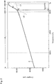
- Fig. 2 shows an example of the results of measurement of the coefficient of linear thermal expansion ( ⁇ ).
- This Fig. is one showing the results of measurement obtained by a sample in Example 28.
- the coefficient of linear thermal expansion ( ⁇ ) was estimated to be about 108 ⁇ 10 -7 /°C.
- the coefficient of linear thermal expansion is not higher than 120 ⁇ 10 -7 /°C even at the maximum.
- the coefficient of linear thermal expansion is not higher than 114 ⁇ 10 -7 /°C even at the maximum, and thus with these samples, the coefficient of thermal expansion is low.
- glasses of the present invention (samples in Examples 1 to 37) were confirmed to show low coefficients of linear thermal expansion of not higher than 120 ⁇ 10 -7 /°C. Accordingly, when a LED assembly is covered by a glass covering material having the same composition as these samples, it is possible to avoid breakage of the covering material which is likely to occur due to the difference in the coefficient of thermal expansion between the covering material and other components in the step of cooling the covering material or during the storage period of the LED device.
- the glass transition temperature (Tg) of each sample was measured.
- the glass transition temperature (Tg) was measured as follows, by using the results of measurement obtained by the above measurement of the coefficient of linear thermal expansion ( ⁇ ) (raw data).
- Fig. 2 shows an operation at the time of measuring the glass transition temperature (Tg) of each sample.
- curve A is an example of the results of measurement obtained in the measurement of the coefficient of linear thermal expansion ( ⁇ ).
- the abscissa represents the temperature (°C) of the test sample, and the ordinate represents the elongation ( ⁇ m) of the test sample.
- curve A has three regions i.e. a linear region RL (a region in which the elongation to the temperature can be approximated substantially by a linear line), a peak region RP (a region of ⁇ 10°C with the temperature Tp where the elongation become maximum at the center) and a transition region RT between the two.
- linear region RL a region in which the elongation to the temperature can be approximated substantially by a linear line
- peak region RP a region of ⁇ 10°C with the temperature Tp where the elongation become maximum at the center
- transition region RT between the two.
- Tg glass transition temperature
- the glass transition temperature (Tg) is a low value of not higher than 321°C even at the maximum.
- the glass of the present invention is useful for covering and/or sealing of a LED element to be used for e.g. a backlight source for liquid crystal panels, general illumination, head light for automobiles, etc.
Landscapes
- Chemical & Material Sciences (AREA)
- Life Sciences & Earth Sciences (AREA)
- Engineering & Computer Science (AREA)
- Chemical Kinetics & Catalysis (AREA)
- General Chemical & Material Sciences (AREA)
- Geochemistry & Mineralogy (AREA)
- Materials Engineering (AREA)
- Organic Chemistry (AREA)
- Glass Compositions (AREA)
- Led Device Packages (AREA)
Abstract
Description
- The present invention relates to glass, particularly glass to be used as a covering material for a light-emitting device such as a light-emitting diode (LED) device.
- Heretofore, in a light-emitting diode (LED) device, an organic material such as a resin has been used as a covering material to seal or cover a LED element and a substrate supporting such a LED element (hereinafter generally referred to as a "LED assembly". However, a problem has been pointed out such that the covering material made of a resin is susceptible to deterioration by heat formed during the operation of the LED device, light and/or the environmental moisture, and its useful life is short.
- Therefore, for covering a LED assembly, it has been studied to use a covering material made of glass which is more stable as compared with a resin. However, if conventional common silicate glass is used as a coating material for a LED assembly, a covering treatment temperature of about 500°C or higher is required from the restriction of the glass softening point. For various components constituting a LED device, covering treatment at such high temperature is not desirable from the viewpoint of the reliability. In order to employ glass as a covering material, glass is required which is capable of carrying out covering treatment of a LED assembly at a covering treatment temperature of less than 500°C, particularly at most 400°C.
- Further,
JP-A-7-696721 - However, the glass disclosed in
JP-A-7-696721 - The glass disclosed in
JP-A-7-696721 - Further, the glass disclosed in
JP-A-7-696721 JP-A-7-696721 - Therefore, even if good adhesion is obtained between the glass covering material and the LED element at the time of the covering treatment, in the subsequent cooling process or storage process of the LED device, the covering material is likely to be cracked or broken due to the difference in the coefficient of thermal expansion between them. If the sealing material has such cracks, the function as the sealing material will be substantially impaired.
- Thus, there still is a strong demand for glass which can be used as a covering material for a LED assembly and which has a low coefficient of thermal expansion and a long-term stability.
- The present invention has been made under these circumstances, and it is an object of the present invention to provide glass which is capable of covering at a covering treatment temperature of at most 400°C and which has a low coefficient of thermal expansion and excellent weather resistance. Further, another object of the present invention is to provide a covering material for a light-emitting device, made of such glass, and a light-emitting device having such a covering material.
- The present invention provides glass comprising, as represented by mol% based on oxides, from 29% to 33% of P2O5, from 43% to 58% of SnO, from 11 % to 25% of ZnO, from 0.1 % to 2% of Ga2O3, from 0.5% to 5% of CaO, and from 0% to 1% of SrO, provided that the sum X of ZnO, Ga2O3 and CaO is within a range of from 13% to 27%, as represented by mol% based on oxides.
- Here, the glass of the present invention preferably comprises, as represented by mol% based on oxides, from 30% to 33% of P2O5, from 44% to 53% of SnO, from 13% to 24% of ZnO, from 0.1% to 2% of Ga2O3, from 0.5% to 3% of CaO, and from 0% to 1% of SrO, wherein said X is within a range of from 18% to 26%.
- Further, the glass of the present invention preferably has a coefficient of linear thermal expansion of at most 120×10-7/°C.
- Further, the present invention provides a glass covering material for a light-emitting device, which is made of the glass having the above-described characteristics.
- In such a case, the light-emitting device may be a light-emitting device using a LED element.
- Further, the present invention provides a light-emitting device comprising an optical element disposed on a base substrate, and a covering material covering the optical element, wherein the covering material is made of the glass having the above-described characteristics.
- Here, in the light-emitting device of the present invention, the optical element may be LED.
- According to the present invention, it is possible to provide glass which is capable of covering at a covering treatment temperature of at most 400°C and which has a low coefficient of thermal expansion and excellent weather resistance. Further, according to the present invention, it is possible to provide a covering material for a light-emitting device, which is made of such glass, and a light-emitting device having such a covering material.
-
Fig. 1 is a view schematically illustrating an example in cross-section of a light-emitting device by the present invention. -
Fig. 2 is a diagram schematically illustrating an operation to obtain a glass transition temperature (Tg) from a temperature change in elongation of a sample. - Now, with reference to the drawings, an embodiment of the present invention will be described in detail. Here, the following embodiment is presented as an example, and it should be understood that various modifications may be made within a range not departing from the technical concept of the present invention.
- The present invention provides glass comprising, as represented by mol% based on oxides, from 29% to 33% of P2O5, from 43% to 58% of SnO, from 11 % to 25% of ZnO, from 0.1 % to 2% of Ga2O3, from 0.5% to 5% of CaO, and from 0% to 1% of SrO, provided that the sum X of ZnO, Ga2O3 and CaO is within a range of from 13% to 27%, as represented by mol% based on oxides.
- With such glass of the present invention, the softening point is controlled to be less than 400°C, and covering treatment at a temperature of at most 400°C becomes possible. Further, the glass of the present invention has such a characteristic that it has excellent weather resistance. Further, the glass of the present invention has a coefficient of linear thermal expansion α which is controlled to be at most 120×10-7/°C. Therefore, even when the glass of the present invention is used for covering treatment of a common LED assembly containing a LED element constituted by an InGaN/GaN semiconductor layer laminated on e.g. a sapphire substrate, it is possible to prevent a problem such that the covering material undergoes cracking or the covering material undergoes breakage due to a difference in the coefficient of linear thermal expansion between the glass covering material and the LED element.
- By such characteristics, the glass of the present invention is sufficiently useful as a covering material for covering treatment of a light-emitting device at a temperature of at most 400°C. Further, when the glass of the present invention is used as a covering material for a light-emitting device, it is possible to provide a light-emitting device which exhibits stable properties over a long period of time.
- Now, general characteristics and suitable contents of various components contained in the glass of the present invention will be described. Here, the content of each component mentioned hereinafter is represented by mol% based on oxides, unless otherwise specified. Further, the characteristics of each component mentioned hereinafter are merely exemplary and do not deny other characteristics and effects which such a component may have.
- P2O5 is an essential component and a component to stabilize the glass and it is contained within a range of from 29% to 33% in the glass of the present invention. If the content of P2O5 is less than 29%, the glass transition temperature (Tg) tends to be high. Further, if it is attempted to prevent the increase of the glass transition temperature (Tg), it becomes necessary to increase the amount of SnO, whereby the coefficient of linear thermal expansion (α) is likely to be large. On the other hand, if the content of P2O5 exceeds 33%, the weather resistance tends to deteriorate. The content of P2O5 is particularly preferably within a range of from 30% to 33%.
- SnO is an essential component and a component to increase the fluidity of the glass, and it is contained within a range of from 43% to 58% in the glass of the present invention. If the content of SnO is less than 43%, the glass transition temperature (Tg) is likely to be high. On the other hand, if the content of SnO exceeds 58%, the weather resistance tends to deteriorate. The content of SnO is particularly preferably within a range of from 44% to 53%.
- ZnO is an essential component and a component to increase the fluidity of the glass, and it is contained within a range of from 11 % to 25% in the glass of the present invention. If the content of ZnO is less than 11 %, the coefficient of linear thermal expansion (α) is likely to be large. On the other hand, if the content of ZnO exceeds 25%, the glass transition temperature (Tg) is likely to be high. The content of ZnO is particularly preferably within a range of from 13% to 24%.
- Ga2O3 is an essential component and a component to improve the weather resistance of the glass, and it is contained within a range of from 0.1 % to 2% in the glass of the present invention. If the content of Ga2O3 is less than 0.1 %, the weather resistance of the glass may not be sufficiently improved. On the other hand, if the content of Ga2O3 exceeds 2%, the glass transition temperature (Tg) is likely to be high. Further, from the viewpoint of the costs, it is preferred to reduce the amount of Ga2O3 as far as possible.
- CaO is an essential component and a component to improve the weather resistance of the glass, and it is contained within a range of from 0.5% to 5% in the glass of the present invention. If the content of CaO is less than 0.5%, the weather resistance of the glass may not be sufficiently improved. On the other hand, if the content of CaO exceeds 5%, the glass transition temperature (Tg) is likely to be high. The content of CaO is particularly preferably within a range of from 0.5% to 3%.
- SrO is a component to improve the weather resistance of the glass, and it is contained in an amount of up to 1% at the maximum in the glass of the present invention. However, addition of SrO is optional. If the content of SrO exceeds 1%, the glass transition temperature (Tg) is likely to be high.
- Further, in the glass of the present invention, the sum X of ZnO+Ga2O3+Ca0 is within a range of from 13% to 27%, preferably within a range of from 18% to 26%. If X is less than 13%, the coefficient of linear thermal expansion (α) of the glass is likely to be large. On the other hand, if X exceeds 27%, the glass transition temperature (Tg) is likely to be high.
- The glass of the present invention is preferably composed substantially of the above components. However, within a range not to impair the purpose of the present invention, other components, e.g. Bi2O3, Y2O3, Gd2O3, Ce2O3, CeO2, TiO2, GeO2, TeO2, Ta2O5, etc. may be added.
- Further, the glass of the present invention preferably contains substantially no PbO. Further, the glass of the present invention preferably contains substantially no Li2O, Na2O or K2O. If such compounds are present in a significant content in the glass, deterioration due to ionic diffusion to a semiconductor element is likely to occur. Further, the glass of the present invention preferably contains substantially no MnO, Fe2O3, Co2O3, WO3, etc. If these compounds are present in a significant content in the glass, the transparency of the glass is likely to be impaired by coloration.
- The glass transition temperature (Tg) of the glass of the present invention is controlled to be at most about 325°C. The reason is such that if the glass transition temperature (Tg) becomes higher than 325°C, the sealing temperature is likely to be at least 400°C. The glass transition temperature (Tg) is preferably less than 320°C.
- The coefficient of linear thermal expansion (α) of the glass of the present invention is at most 120×10-7/°C, preferably at most about 115×10-7/°C. If the coefficient of linear thermal expansion (α) exceeds 120×10-7/°C, after covering a LED assembly by the glass covering material, in a step of cooling such a LED device to room temperature or in subsequent steps thereof, the glass covering material is likely to undergo cracking, caused by the difference in the coefficient of thermal expansion between the glass covering material and the LED element.
- The glass of the present invention having the above-described composition is used as a covering material for a light-emitting device having a glass covering portion. Therefore, a construction of a light-emitting device wherein the glass of the present invention is applied as a covering material will be described with reference to a LED device as an example. Further, the glass of the present invention is also applicable as a covering material for other light-emitting devices.
-
Fig. 1 schematically illustrates an example in cross-section of aLED device 1 according to the present invention. TheLED device 1 comprises abase substrate 120, a light-emittingportion 100 mounted on thebase substrate 120, and a coveringportion 110 covering the light-emittingportion 100. - On the surface of the
base substrate 120 on the side where the light-emittingportion 100 is mounted, a plurality of wirings 130 (130a and 130b) are formed. - The
base substrate 120 is constituted, for example, by a substrate made of an inorganic material such as alumina and having a rectangular shape with a thickness of from 0.2 mm to 1.2 mm. Thewirings base substrate 120 may, for example, be gold wirings formed by a gold paste. - The light-emitting
portion 100 is constructed by setting theLED element 102 on asubstrate 101 for element. TheLED element 102 has apositive electrode 103 and anegative electrode 104 on the opposite side to thesubstrate 101 for element. The light-emittingportion 100 is set on thebase substrate 120, so that theseelectrodes wirings base substrate 120. - The
LED element 102 is constituted by e.g. LED which emits ultraviolet light or blue light having a wavelength of from 360 to 480 nm, and LED having a light-emitting layer side of InGaN having In added to GaN and having a quantum well structure (InGaN type LED) may be mentioned as a typical example. However, LED having other specifications may, of course, be used. The coefficient of linear thermal expansion of thesubstrate 101 for element is, for example, from 70×10-7 to 90×10-7/°C. In a usual case, as the material for thesubstrate 101 for element, sapphire having a coefficient of linear thermal expansion of about 80×10-7/°C is used. - The covering portion 109 is constituted by the covering
material 115. This coveringmaterial 115 is made of the glass of the present invention having the above-described composition. - In such a
LED device 1, the coveringmaterial 115 covering the light-emittingportion 100 can be formed at a covering treatment temperature of at most 400°C. Accordingly, it is possible to prevent a thermal damage of each component constituting theLED device 1. Further, this coveringmaterial 115 has a low coefficient of linear thermal expansion (α). Therefore, it is possible to avoid breakage of the covering material which may occur due to the difference in the coefficient of linear thermal expansion between the covering material and other components, for example, in a cooling step of the covering material or the storage period of the LED device. Further, this coveringmaterial 115 has excellent weather resistance. Therefore, it is possible to prevent deterioration after the use for a long period of time, which may be problematic in the case of conventional glass. Thus, in the present invention, it is possible to provide a LED device which exhibits a stable light emission over a long period of time. - Now, the present invention will be described in further detail with reference to Examples, but it should be understood that the present invention is by no means limited thereto.
- By the following method, glass (glass of Example 1) comprising, as calculated by mol% based on oxides, 30% of P2O5, 46% of SnO, 20.5% of ZnO, 0.5% of Ga2O3 and 3% of CaO, was prepared.
- Firstly, in a glove box furnace maintaining a nitrogen atmosphere having a dew point of at most -50°C, prescribed amounts of tin pyrophosphate (Sn2P2O7, manufactured by Nippon Chemical Industrial Co., Ltd.), tin oxide (SnO, manufactured by NIHON KAGAKU SANGYO CO., LTD.), zinc metaphosphate (Zn(PO3)2, manufactured by Nippon Chemical Industrial Co., Ltd.), calcium metaphosphate (Ca(PO3)2, manufactured by Nippon Chemical Industrial Co., Ltd.) and gallium oxide (GaO) were weighed, then sealed in a plastic bag and agitated for about one minute by a hand to mix the powder homogeneously.
- Then, the obtained solid product was transferred to a room having a dew point of at most -70°C and put in a quartz crucible. A quartz cover was put on the crucible, and the crucible was maintained at 900°C for 30 minutes to melt the solid product. After completion of the melting treatment, this crucible was taken out from the furnace. Further, in order to mold the melt into a plate glass, molten glass in the crucible was introduced into a carbon mold. Thereafter, glass taken out from this carbon mold was put into a separate electric furnace maintained at 315°C and maintained in this electric furnace for one hour and then cooled to room temperature over a period of 12 hours. The foregoing operation was all carried out in a glove box having a nitrogen atmosphere.
- Via such a step, glass of Example 1 was obtained.
- Further, in the above step, by using anhydrides for all powder materials and carrying out the operation in a sufficiently dried atmosphere having a low dew point, it was possible to minimize the moisture content in glass. In a case where the moisture content in glass may be large or in a case where a step of removing moisture later is included, it is also possible to use a liquid orthophosphoric acid material, etc.
- Further, in the above step, melting was carried out in a nitrogen atmosphere in order to prevent a change of tin having a valency of +2 in the material to a valency of +4 during the melting (oxidation reaction). However, there is also a method wherein melting is carried out in atmospheric air by adding succharose or the like to the material to let excess oxygen burn off thereby to prevent an oxidation reaction in the glass melt.
- By the same method as in Example 1, glass (glass of Example 2) comprising, as calculated by mol% based on oxides, 30% of P2O5, 44% of SnO, 21 % of ZnO, 2% of Ga2O3 and 3% of CaO, was prepared.
- By the same method as in Example 1, glass (glass of Example 3) comprising, as calculated by mol% based on oxides, 30% of P2O5, 46% of SnO, 19% of ZnO, 2% of Ga2O3 and 3% of CaO, was prepared.
- By the same method as in Example 1, glass (glass of Example 4) comprising, as calculated by mol% based on oxides, 30% of P2O5, 48% of SnO, 17% of ZnO, 2% of Ga2O3 and 3% of CaO, was prepared.
- By the same method as in Example 1, glass (glass of Example 5) comprising, as calculated by mol% based on oxides, 30% of P2O5, 50% of SnO, 15% of ZnO, 2% of Ga2O3 and 3% of CaO, was prepared.
- By the same method as in Example 1, glass (glass of Example 6) comprising, as calculated by mol% based on oxides, 30% of P2O5, 52% of SnO, 13% of ZnO, 2% of Ga2O3 and 3% of CaO, was prepared.
- By the same method as in Example 1, glass (glass of Example 7) comprising, as calculated by mol% based on oxides, 30% of P2O5, 46% of SnO, 20% of ZnO, 1% of Ga2O3 and 3% of CaO, was prepared.
- By the same method as in Example 1, glass (glass of Example 8) comprising, as calculated by mol% based on oxides, 30% of P2O5, 46% of SnO, 20% of ZnO, 2% of Ga2O3 and 2% of CaO, was prepared.
- By the same method as in Example 1, glass (glass of Example 9) comprising, as calculated by mol% based on oxides, 30% of P2O5, 46% of SnO, 21% of ZnO, 2% of Ga2O3 and 1% of CaO, was prepared.
- By the same method as in Example 1, glass (glass of Example 10) comprising, as calculated by mol% based on oxides, 30% of P2O5, 46% of SnO, 21.5% of ZnO, 2% of Ga2O3 and 0.5% of CaO, was prepared.
- By the same method as in Example 1, glass (glass of Example 11) comprising, as calculated by mol% based on oxides, 30% of P2O5, 46% of SnO, 22% of ZnO, 1% of Ga2O3 and 1% of CaO, was prepared.
- By the same method as in Example 1, glass (glass of Example 12) comprising, as calculated by mol% based on oxides, 30% of P2O5, 46% of SnO, 23% of ZnO, 0.5% of Ga2O3 and 0.5% of CaO, was prepared.
- By the same method as in Example 1, glass (glass of Example 13) comprising, as calculated by mol% based on oxides, 30% of P2O5, 46% of SnO, 20.7% of ZnO, 0.3% of Ga2O3 and 3% of CaO, was prepared.
- By the same method as in Example 1, glass (glass of Example 14) comprising, as calculated by mol% based on oxides, 30% of P2O5, 46% of SnO, 20.9% of ZnO, 0.1 % of Ga2O3 and 3% of CaO, was prepared.
- By the same method as in Example 1, glass (glass of Example 15) comprising, as calculated by mol% based on oxides, 30% of P2O5, 45% of SnO, 21 % of ZnO, 1% of Ga2O3 and 3% of CaO, was prepared.
- By the same method as in Example 1, glass (glass of Example 16) comprising, as calculated by mol% based on oxides, 30% of P2O5, 45% of SnO, 21.5% of ZnO, 0.5% of Ga2O3 and 3% of CaO, was prepared.
- By the same method as in Example 1, glass (glass of Example 17) comprising, as calculated by mol% based on oxides, 30% of P2O5, 45% of SnO, 21.7% of ZnO, 0.3% of Ga2O3 and 3% of CaO, was prepared.
- By the same method as in Example 1, glass (glass of Example 18) comprising, as calculated by mol% based on oxides, 30% of P2O5, 45% of SnO, 21.9% of ZnO, 0.1 % of Ga2O3 and 3% of CaO, was prepared.
- By the same method as in Example 1, glass (glass of Example 19) comprising, as calculated by mol% based on oxides, 30% of P2O5, 45% of SnO, 22.9% of ZnO, 0.1 % of Ga2O3 and 2% of CaO, was prepared.
- By the same method as in Example 1, glass (glass of Example 20) comprising, as calculated by mol% based on oxides, 30% of P2O5, 45% of SnO, 23.9% of ZnO, 0.1% of Ga2O3 and 1% of CaO, was prepared.
- By the same method as in Example 1, glass (glass of Example 21) comprising, as calculated by mol% based on oxides, 31% of P2O5, 46% of SnO, 18% of ZnO, 2% of Ga2O3 and 3% of CaO, was prepared.
- By the same method as in Example 1, glass (glass of Example 22) comprising, as calculated by mol% based on oxides, 31% of P2O5, 46% of SnO, 19% of ZnO, 1% of Ga2O3 and 3% of CaO, was prepared.
- By the same method as in Example 1, glass (glass of Example 23) comprising, as calculated by mol% based on oxides, 31% of P2O5, 46% of SnO, 19.5% of ZnO, 0.5% of Ga2O3 and 3% of CaO, was prepared.
- By the same method as in Example 1, glass (glass of Example 24) comprising, as calculated by mol% based on oxides, 31% of P2O5, 46% of SnO, 20% of ZnO, 1% of Ga2O3 and 2% of CaO, was prepared.
- By the same method as in Example 1, glass (glass of Example 25) comprising, as calculated by mol% based on oxides, 31% of P2O5, 46% of SnO, 21% of ZnO, 1% of Ga2O3 and 1% of CaO, was prepared.
- By the same method as in Example 1, glass (glass of Example 26) comprising, as calculated by mol% based on oxides, 31 % of P2O5, 46% of SnO, 22% of ZnO, 0.5% of Ga2O3 and 0.5% of CaO, was prepared.
- By the following method, glass (glass of Example 27) comprising, as calculated by mol% based on oxides, 31 % of P2O5, 46% of SnO, 21.5% of ZnO, 0.5% of Ga2O3, 0.5% of CaO and 0.5% of SrO, was prepared.
- Firstly, in a glove box furnace maintaining a nitrogen atmosphere having a dew point of at most -50°C, prescribed amounts of tin pyrophosphate (Sn2P2O7, manufactured by Nippon Chemical Industrial Co., Ltd.), tin oxide (SnO, manufactured by NIHON KAGAKU SANGYO CO., LTD.), zinc metaphosphate (Zn(PO3)2, manufactured by Nippon Chemical Industrial Co., Ltd.), calcium metaphosphate (Ca(PO3)2, manufactured by Nippon Chemical Industrial Co., Ltd.), gallium oxide (GaO) and strontium carbonate (SrCO3) were weighed, then sealed in a plastic bag and agitated for about one minute by a hand to mix the powder homogeneously.
- Then, the obtained solid product was transferred to a room having a dew point of at most -70°C and put in a quartz crucible. A quartz cover was put on the crucible, and then, this crucible was maintained at 900°C for 30 minutes to melt the solid product. After completion of the melting treatment, this crucible was taken out from the furnace. Further, in order to mold the melt into a plate glass, molten glass in the crucible was injected into a carbon mold. Thereafter, glass taken out from this carbon mold was put in a separate electric furnace maintained at 315°C and maintained for one hour in this electric furnace and then cooled to room temperature over a period of 12 hours. The foregoing operation was all carried out in a glove box having a nitrogen atmosphere.
- Via such a step, glass of Example 27 was obtained.
- By the same method as in Example 1, glass (glass of Example 28) comprising, as calculated by mol% based on oxides, 32% of P2O5, 45% of SnO, 18% of ZnO, 2% of Ga2O3 and 3% of CaO, was prepared.
- By the same method as in Example 1, glass (glass of Example 29) comprising, as calculated by mol% based on oxides, 32% of P2O5, 45% of SnO, 19% of ZnO, 1% of Ga2O3 and 3% of CaO, was prepared.
- By the same method as in Example 1, glass (glass of Example 30) comprising, as calculated by mol% based on oxides, 32% of P2O5, 45% of SnO, 19.5% of ZnO, 0.5% of Ga2O3 and 3% of CaO, was prepared.
- By the same method as in Example 1, glass (glass of Example 31) comprising, as calculated by mol% based on oxides, 32% of P2O5, 45% of SnO, 20% of ZnO, 1% of Ga2O3 and 2% of CaO, was prepared.
- By the same method as in Example 1, glass (glass of Example 32) comprising, as calculated by mol% based on oxides, 32% of P2O5, 45% of SnO, 21 % of ZnO, 1% of Ga2O3 and 1% of CaO, was prepared.
- By the same method as in Example 1, glass (glass of Example 33) comprising, as calculated by mol% based on oxides, 32% of P2O5, 45% of SnO, 22% of ZnO, 0.5% of Ga2O3 and 0.5% of CaO, was prepared.
- By the same method as in Example 1, glass (glass of Example 34) comprising, as calculated by mol% based on oxides, 32% of P2O5, 45% of SnO, 21.5% of ZnO, 0.5% of Ga2O3, 0.5% of CaO and 0.5% of SrO, was prepared.
- By the same method as in Example 1, glass (glass of Example 35) comprising, as calculated by mol% based on oxides, 33% of P2O5, 45% of SnO, 20.5% of ZnO, 0.5% of Ga2O3 and 1% of CaO, was prepared.
- By the same method as in Example 1, glass (glass of Example 36) comprising, as calculated by mol% based on oxides, 29% of P2O5, 58% of SnO, 11.5% of ZnO, 0.5% of Ga2O3 and 1% of CaO, was prepared.
- By the same method as in Example 1, glass (glass of Example 37) comprising, as calculated by mol% based on oxides, 30% of P2O5, 54% of SnO, 11 % of ZnO, 2% of Ga2O3 and 3% of CaO, was prepared.
- By the same method as in Example 1, glass (glass of Example 38) comprising, as calculated by mol% based on oxides, 28% of P2O5, 60% of SnO, 10.5% of ZnO, 0.5% of Ga2O3 and 1% of CaO, was prepared.
- By the same method as in Example 1, glass (glass of Example 39) comprising, as calculated by mol% based on oxides, 28% of P2O5, 60% of SnO, 11 % of ZnO and 1% of CaO, was prepared. In this Example 39, Ga2O3 is not added, as is different from Example 1.
- By the same method as in Example 1, glass (glass of Example 40) comprising, as calculated by mol% based on oxides, 29% of P2O5, 58% of SnO, 12% of ZnO and 1% of CaO, was prepared. In this Example 40, Ga2O3 is not added, as is different from Example 1.
- By the same method as in Example 1, glass (glass of Example 41) comprising, as calculated by mol% based on oxides, 33% of P2O5, 45% of SnO, 21% of ZnO and 1% of CaO, was prepared. In this Example 41, Ga2O3 is not added, as is different from Example 1.
- By the same method as in Example 1, glass (glass of Example 42) comprising, as calculated by mol% based on oxides, 35% of P2O5, 41% of SnO, 22.5% of ZnO, 0.5% of Ga2O3 and 1% of CaO, was prepared.
- By the same method as in Example 1, glass (glass of Example 43) comprising, as calculated by mol% based on oxides, 35% of P2O5, 41 % of SnO, 23% of ZnO and 1% of CaO, was prepared. In this Example 43, Ga2O3 is not added, as is different from Example 1.
- In the following Tables 1 and 2, the compositions of samples in the respective Examples are summarized. In Table 1, Examples 1 to 20 are Working Examples of the present invention. In Table 2, Examples 21 to 37 are Working Examples of the present invention, and Examples 38 to 43 are Comparative Examples.
TABLE 1 Composition (mol%) Examples 1 2 3 4 5 6 7 8 9 10 11 12 13 14 15 16 17 18 19 20 P2O5 30 30 30 30 30 30 30 30 30 30 30 30 30 30 30 30 30 30 30 30 SnO 46 44 46 48 50 52 46 46 46 46 46 46 46 46 45 45 45 45 45 45 ZnO 20.5 21 19 17 15 13 20 20 21 21.5 22 23 20.7 20.9 21 21.5 21.7 21.9 22.9 23.9 Ga2O3 0.5 2 2 2 2 2 1 2 2 2 1 0.5 0.3 0.1 1 0.5 0.3 0.1 0.1 0.1 CaO 3 3 3 3 3 3 3 2 1 0.5 1 0.5 3 3 3 3 3 3 2 1 SrO 0 0 0 0 0 0 0 0 0 0 0 0 0 0 0 0 0 0 0 0 X* 24 26 24 22 20 18 24 24 24 24 24 24 24 24 25 25 25 25 25 25 Glass transition temperature Tg (°C) 312 321 320 316 312 309 312 312 311 307 307 303 311 317 321 314 314 314 312 308 Coefficient of linear thermal expansion α (×10-7/°C) 105 105 105 107 110 114 105 105 105 104 106 104 107 108 107 106 107 107 105 108 Weather resistance (500 hr) ○ ○ ○ ○ ○ ○ ○ ○ ○ ○ ○ ○ ○ ○ ○ ○ ○ ○ ○ ○ Weather resistance (1,000 hr) ○ ○ ○ ○ ○ ○ ○ ○ ○ ○ ○ ○ ○ ○ ○ ○ ○ ○ ○ ○ X*: Sum of ZnO, Ga2O3 and CaO 

- In Tables 1 and 2, X is the sum (as represented by mol% based on oxides) of ZnO, Ga2O3 and CaO.
- In each of glasses in Example 1 to 43, no coloration or turbidity due to devitrification was observed, and these glasses were transparent.
- By the following method, the weather resistance of a sample of glass in each Example was evaluated.
- Firstly, each sample was processed into a flat plate having a thickness of 2 mm, and the front surface and rear surface were polished until they became mirror surfaces. Using the polished sample, the spectral transmittance at a wavelength of 460 nm was measured. For the measurement, a spectral transmittance measuring device (called LAMBDA 950, manufactured by Perkin Elmer) was used. The obtained transmittance is designated as V0.
- Then, in order to evaluate the weather resistance of each sample, each sample was put in a constant temperature and humidity tank at 80°C under a relative humidity of 80% and maintained for a prescribed time (e.g. time t). Thereafter, each sample was taken out, and the spectral transmittance was measured by the above-described method. The obtained transmittance is designated as Vt. Thereafter, each sample was returned again into the constant temperature and humidity tank.
- This operation was repeated up to 500 hours. The spectral transmittance of each sample obtained after the 500 hours is designated as V500. Here, in a case where the ratio of the spectral transmittance V500 after the 500 hours to the transmittance V0 before placing the sample in the constant temperature and humidity tank (i.e. V500/V0) became at least 0.9, the weather resistance of such a sample was judged to be good. On the other hand, in a case where V500/V0 became less than 0.9, the weather resistance of such a sample was evaluated to be poor, and the test was completed.
- Further, with respect to a sample which showed good light resistance with the ratio V500/V0 being at least 0.9, evaluation of the weather resistance was further continued to 1,000 hours.
- After completion of the test for 1,000 hours, each sample was taken out, and the spectral transmittance was measured by the above-described method. The obtained transmittance of the sample is designated as V1000. By using this value, the ratio of the spectral transmittance V1,000 after the 1,000 hours to the transmittance V0 before the sample was placed in the constant temperature and humidity tank (i.e. V1,000/V0) was obtained.
- A sample having a ratio V1000/V0 of at least 0.9 was judged to be a sample having excellent weather resistance.
- In the above Tables 1 and 2, the results of the weather resistance test obtained with respect to the respective samples are summarized.
- In Tables 1 and 2, symbol mark "O" in the space for weather resistance (500 hr) represents that the sample had V500/V0 of at least 0.9. Likewise, symbol mark "O" in the space for weather resistance (1,000 hr) represents that the sample had V1000/V0 of at least 0.9. Further, in Tables 1 and 2, symbol mark "x" in the space for weather resistance (500 hr) represents that the sample had V500/V0 of less than 0.9, and symbol "x" in the space for weather resistance (1,000 hr) represents that the sample had V1000/V0 of less than 0.9. Symbol mark "-" means that the test for 1,000 hours was not carried out, since the weather resistance after 500 hours of the sample V500/V0 was less than 0.9.
- From the Tables, it is evident that the samples in Examples 41 to 43 (the samples in Comparative Examples) did not show good weather resistance. On the other hand, it is evident that the samples in Examples 1 to 40 showed good weather resistance in the test for 500 hours. Particularly, it is evident that the samples in Examples 1 to 36 and 38 showed good weather resistance also in the test for 1,000 hours and thus has excellent weather resistance.
- Thus, the glasses of the present invention (samples in Examples 1 to 37) were confirmed to show stabilized weather resistance for a long period of time. Particularly, the samples in Examples 1 to 36 were confirmed to have excellent weather resistance.
- Then, each sample was processed into a cylindrical shape having a diameter of 5 mm and a length of 20 mm, and using this test sample, the coefficient of linear thermal expansion (α) was measured. For the measurement of the coefficient of linear thermal expansion (α), a thermal dilatometer (horizontal differential detection system thermal dilatometer TD501 0, manufactured by Bruker AXS) was used. By using this thermal expansion meter, each test sample was heated to 300°C at a temperature raising rate of 10°C/min to measure the elongation of the test sample at each temperature. Specifically, the elongation values of the test sample at from 100 to 300°C were measured every 25°C, and the average value was taken as the coefficient of linear thermal expansion (α).
-
Fig. 2 shows an example of the results of measurement of the coefficient of linear thermal expansion (α). This Fig. is one showing the results of measurement obtained by a sample in Example 28. In the case of the sample in Example 28, the coefficient of linear thermal expansion (α) was estimated to be about 108×10-7/°C. - In the above Tables 1 and 2, the results of measurement of coefficients of thermal expansion obtained with respect to the respective samples are summarized.
- In the above-described weather resistance test, also samples in Examples 38 to 40 corresponding to Comparative Examples (particularly the sample in Example 38) showed good weather resistance. However, from the results of measurement of the coefficient of linear thermal expansion (α), it was found that with samples in Examples 38 to 40, the coefficient of linear thermal expansion showed a high value of at least 122×10-7/°C. Therefore, if a LED assembly is covered by a glass covering material having the same composition as these samples, cracking is likely to occur in the glass covering material due to the difference in the coefficient of thermal expansion between the glass covering material and the LED element in the process of cooling this LED device to room temperature or in the subsequent steps.
- Whereas, with samples in Examples 1 to 37, the coefficient of linear thermal expansion is not higher than 120×10-7/°C even at the maximum. Especially, with samples in Examples 1 to 35, the coefficient of linear thermal expansion is not higher than 114×10-7/°C even at the maximum, and thus with these samples, the coefficient of thermal expansion is low.
- Thus, glasses of the present invention (samples in Examples 1 to 37) were confirmed to show low coefficients of linear thermal expansion of not higher than 120×10-7/°C. Accordingly, when a LED assembly is covered by a glass covering material having the same composition as these samples, it is possible to avoid breakage of the covering material which is likely to occur due to the difference in the coefficient of thermal expansion between the covering material and other components in the step of cooling the covering material or during the storage period of the LED device.
- Then, the glass transition temperature (Tg) of each sample was measured. The glass transition temperature (Tg) was measured as follows, by using the results of measurement obtained by the above measurement of the coefficient of linear thermal expansion (α) (raw data).
-
Fig. 2 shows an operation at the time of measuring the glass transition temperature (Tg) of each sample. - In
Fig. 2 , curve A is an example of the results of measurement obtained in the measurement of the coefficient of linear thermal expansion (α). The abscissa represents the temperature (°C) of the test sample, and the ordinate represents the elongation (µm) of the test sample. - In a usual case, curve A has three regions i.e. a linear region RL (a region in which the elongation to the temperature can be approximated substantially by a linear line), a peak region RP (a region of ±10°C with the temperature Tp where the elongation become maximum at the center) and a transition region RT between the two.
- Firstly, in this curve A, linear line L1 fitting to the linear region RL is drawn. Then, in the transition region RT in curve A, inflection point C of the curve is obtained. Further, linear line L2 which passes through the inflection point C and which contacts curve A, is drawn.
- Intersection G of the two linear lines L1 and L2 thus obtained is taken as the glass transition temperature (Tg).
- In the above Tables 1 and 2, the results of measurement of the glass transition temperatures Tg obtained with respect to the respective samples are summarized.
- From the results, it is evident that in each sample, the glass transition temperature (Tg) is a low value of not higher than 321°C even at the maximum.
- From these results, it has been confirmed that by using the glass of the present invention, it is possible to carry out covering treatment at a low temperature of at most 400°C.
- The glass of the present invention is useful for covering and/or sealing of a LED element to be used for e.g. a backlight source for liquid crystal panels, general illumination, head light for automobiles, etc.
- The entire disclosure of Japanese Patent Application No.
2011-010242 filed on January 20, 2011 -
- 1: LED device
- 100: Light-emitting portion
- 101: Substrate for element
- 102: LED element
- 103: Positive electrode
- 104: Negative electrode
- 110: Covering portion
- 115: Covering material
- 120: Base substrate
- 130a, 130b: Wirings
Claims (7)
- Glass comprising, as represented by mol% based on oxides, from 29% to 33% of P2O5, from 43% to 58% of SnO, from 11 % to 25% of ZnO, from 0.1% to 2% of Ga2O3, from 0.5% to 5% of CaO, and from 0% to 1% of SrO, provided that the sum X of ZnO, Ga2O3 and CaO is within a range of from 13% to 27%, as represented by mol% based on oxides.
- The glass according to Claim 1, which comprises, as represented by mol% based on oxides, from 30% to 33% of P2O5, from 44% to 53% of SnO, from 13% to 24% of ZnO, from 0.1 % to 2% of Ga2O3, from 0.5% to 3% of CaO, and from 0% to 1% of SrO, wherein said X is within a range of from 18% to 26%.
- The glass according to Claim 1 or 2, which has a coefficient of linear thermal expansion of at most 120×10-7/°C.
- A glass covering material for a light-emitting device, which is made of the glass as defined in any one of Claims 1 to 3.
- The glass covering material according to Claim 4, wherein the light-emitting device is a light-emitting device using a LED element.
- A light-emitting device comprising an optical element disposed on a base substrate, and a covering material covering the optical element, wherein the covering material is made of the glass as defined in any one of Claims 1 to 3.
- The light-emitting device according to Claim 6, wherein the optical element is LED.
Applications Claiming Priority (1)
| Application Number | Priority Date | Filing Date | Title |
|---|---|---|---|
| JP2011010242A JP5585467B2 (en) | 2011-01-20 | 2011-01-20 | Glass, glass coating material for light emitting device and light emitting device |
Publications (2)
| Publication Number | Publication Date |
|---|---|
| EP2479152A1 true EP2479152A1 (en) | 2012-07-25 |
| EP2479152B1 EP2479152B1 (en) | 2013-12-18 |
Family
ID=45528920
Family Applications (1)
| Application Number | Title | Priority Date | Filing Date |
|---|---|---|---|
| EP12000040.1A Not-in-force EP2479152B1 (en) | 2011-01-20 | 2012-01-04 | Glass, glass covering material for light-emitting device, and light-emitting device |
Country Status (3)
| Country | Link |
|---|---|
| US (1) | US8686465B2 (en) |
| EP (1) | EP2479152B1 (en) |
| JP (1) | JP5585467B2 (en) |
Families Citing this family (5)
| Publication number | Priority date | Publication date | Assignee | Title |
|---|---|---|---|---|
| WO2014162869A1 (en) * | 2013-04-04 | 2014-10-09 | 日本電気硝子株式会社 | Optical glass |
| JP2015151280A (en) * | 2014-02-12 | 2015-08-24 | 日本電気硝子株式会社 | optical glass |
| KR20140128789A (en) * | 2013-04-29 | 2014-11-06 | 삼성디스플레이 주식회사 | Organic light emitting display device and method of manufacturing the same |
| KR102096053B1 (en) * | 2013-07-25 | 2020-04-02 | 삼성디스플레이 주식회사 | Method for manufacturing organic luminescence emitting display device |
| JPWO2015093326A1 (en) * | 2013-12-19 | 2017-03-16 | 旭硝子株式会社 | Glass for metal coating and metal member with glass layer |
Citations (5)
| Publication number | Priority date | Publication date | Assignee | Title |
|---|---|---|---|---|
| JPH0769672A (en) | 1993-06-21 | 1995-03-14 | Corning Inc | Lead-free tin phosphate glass |
| US20050255985A1 (en) * | 2004-05-11 | 2005-11-17 | Tokan Material Technology Co., Ltd. | Lead-free low softening point glass |
| JP2010177548A (en) * | 2009-01-30 | 2010-08-12 | Asahi Glass Co Ltd | Glass powder for coating light emitting element, slurry for coating light emitting element, paste for coating light emitting element, and glass coated light emitting apparatus |
| EP2228350A1 (en) * | 2008-01-10 | 2010-09-15 | Asahi Glass Company, Limited | Glass, coating material for light-emitting device, and light-emitting device |
| JP2011010242A (en) | 2009-06-29 | 2011-01-13 | Kyocera Corp | High-frequency substrate and high-frequency module |
Family Cites Families (4)
| Publication number | Priority date | Publication date | Assignee | Title |
|---|---|---|---|---|
| JP4596358B2 (en) * | 2004-05-11 | 2010-12-08 | 日本電気硝子株式会社 | Glass for sealing |
| WO2008146886A1 (en) | 2007-05-30 | 2008-12-04 | Asahi Glass Company, Limited | Glass for optical device covering, glass-covered light-emitting element, and glass-covered light-emitting device |
| JP2008300536A (en) * | 2007-05-30 | 2008-12-11 | Asahi Glass Co Ltd | Glass-coated light-emitting element and glass-coated light-emitting device |
| WO2011158805A1 (en) * | 2010-06-14 | 2011-12-22 | 旭硝子株式会社 | Sealing material paste, and process for production of electronic device using same |
-
2011
- 2011-01-20 JP JP2011010242A patent/JP5585467B2/en active Active
- 2011-12-29 US US13/339,577 patent/US8686465B2/en active Active
-
2012
- 2012-01-04 EP EP12000040.1A patent/EP2479152B1/en not_active Not-in-force
Patent Citations (5)
| Publication number | Priority date | Publication date | Assignee | Title |
|---|---|---|---|---|
| JPH0769672A (en) | 1993-06-21 | 1995-03-14 | Corning Inc | Lead-free tin phosphate glass |
| US20050255985A1 (en) * | 2004-05-11 | 2005-11-17 | Tokan Material Technology Co., Ltd. | Lead-free low softening point glass |
| EP2228350A1 (en) * | 2008-01-10 | 2010-09-15 | Asahi Glass Company, Limited | Glass, coating material for light-emitting device, and light-emitting device |
| JP2010177548A (en) * | 2009-01-30 | 2010-08-12 | Asahi Glass Co Ltd | Glass powder for coating light emitting element, slurry for coating light emitting element, paste for coating light emitting element, and glass coated light emitting apparatus |
| JP2011010242A (en) | 2009-06-29 | 2011-01-13 | Kyocera Corp | High-frequency substrate and high-frequency module |
Also Published As
| Publication number | Publication date |
|---|---|
| EP2479152B1 (en) | 2013-12-18 |
| JP5585467B2 (en) | 2014-09-10 |
| US8686465B2 (en) | 2014-04-01 |
| JP2012148942A (en) | 2012-08-09 |
| US20120187448A1 (en) | 2012-07-26 |
Similar Documents
| Publication | Publication Date | Title |
|---|---|---|
| US8203169B2 (en) | Glass, coating material for light-emitting devices and light-emitting device | |
| US8198203B2 (en) | Antimony-free glass, antimony-free frit and a glass package that is hermetically sealed with the frit | |
| EP2061727B1 (en) | Durable tungsten-doped tin-fluorophosphate glasses | |
| KR101626840B1 (en) | Lead-free glass material for organic-el sealing, and organic el display formed using same | |
| TWI586624B (en) | Glass-free, flawless glass frit and glass package using the glass seal hermetic seal | |
| US8174045B2 (en) | Glass for covering optical element, glass-covered light-emitting element and glass-covered light-emitting device | |
| KR101758076B1 (en) | Vanadiumbased glass material for local heat sealing, flat display using the same, and method for manufacturing the display | |
| US9878938B2 (en) | Antimony-free glass, antimony-free frit and a glass package that is hermetically sealed with the frit | |
| EP2479152B1 (en) | Glass, glass covering material for light-emitting device, and light-emitting device | |
| JP2008300536A (en) | Glass-coated light-emitting element and glass-coated light-emitting device | |
| JP2010265135A (en) | Glass, glass coating material for light emitting device and light emitting device |
Legal Events
| Date | Code | Title | Description |
|---|---|---|---|
| PUAI | Public reference made under article 153(3) epc to a published international application that has entered the european phase |
Free format text: ORIGINAL CODE: 0009012 |
|
| AK | Designated contracting states |
Kind code of ref document: A1 Designated state(s): AL AT BE BG CH CY CZ DE DK EE ES FI FR GB GR HR HU IE IS IT LI LT LU LV MC MK MT NL NO PL PT RO RS SE SI SK SM TR |
|
| AX | Request for extension of the european patent |
Extension state: BA ME |
|
| 17P | Request for examination filed |
Effective date: 20120823 |
|
| RIC1 | Information provided on ipc code assigned before grant |
Ipc: H01L 33/56 20100101ALI20130708BHEP Ipc: C03C 3/16 20060101AFI20130708BHEP |
|
| GRAP | Despatch of communication of intention to grant a patent |
Free format text: ORIGINAL CODE: EPIDOSNIGR1 |
|
| INTG | Intention to grant announced |
Effective date: 20130829 |
|
| GRAS | Grant fee paid |
Free format text: ORIGINAL CODE: EPIDOSNIGR3 |
|
| GRAA | (expected) grant |
Free format text: ORIGINAL CODE: 0009210 |
|
| AK | Designated contracting states |
Kind code of ref document: B1 Designated state(s): AL AT BE BG CH CY CZ DE DK EE ES FI FR GB GR HR HU IE IS IT LI LT LU LV MC MK MT NL NO PL PT RO RS SE SI SK SM TR |
|
| REG | Reference to a national code |
Ref country code: GB Ref legal event code: FG4D |
|
| REG | Reference to a national code |
Ref country code: CH Ref legal event code: EP |
|
| REG | Reference to a national code |
Ref country code: AT Ref legal event code: REF Ref document number: 645546 Country of ref document: AT Kind code of ref document: T Effective date: 20140115 |
|
| REG | Reference to a national code |
Ref country code: IE Ref legal event code: FG4D |
|
| REG | Reference to a national code |
Ref country code: DE Ref legal event code: R096 Ref document number: 602012000655 Country of ref document: DE Effective date: 20140213 |
|
| REG | Reference to a national code |
Ref country code: NL Ref legal event code: VDEP Effective date: 20131218 |
|
| PG25 | Lapsed in a contracting state [announced via postgrant information from national office to epo] |
Ref country code: SE Free format text: LAPSE BECAUSE OF FAILURE TO SUBMIT A TRANSLATION OF THE DESCRIPTION OR TO PAY THE FEE WITHIN THE PRESCRIBED TIME-LIMIT Effective date: 20131218 Ref country code: LT Free format text: LAPSE BECAUSE OF FAILURE TO SUBMIT A TRANSLATION OF THE DESCRIPTION OR TO PAY THE FEE WITHIN THE PRESCRIBED TIME-LIMIT Effective date: 20131218 Ref country code: HR Free format text: LAPSE BECAUSE OF FAILURE TO SUBMIT A TRANSLATION OF THE DESCRIPTION OR TO PAY THE FEE WITHIN THE PRESCRIBED TIME-LIMIT Effective date: 20131218 Ref country code: FI Free format text: LAPSE BECAUSE OF FAILURE TO SUBMIT A TRANSLATION OF THE DESCRIPTION OR TO PAY THE FEE WITHIN THE PRESCRIBED TIME-LIMIT Effective date: 20131218 Ref country code: NO Free format text: LAPSE BECAUSE OF FAILURE TO SUBMIT A TRANSLATION OF THE DESCRIPTION OR TO PAY THE FEE WITHIN THE PRESCRIBED TIME-LIMIT Effective date: 20140318 |
|
| REG | Reference to a national code |
Ref country code: AT Ref legal event code: MK05 Ref document number: 645546 Country of ref document: AT Kind code of ref document: T Effective date: 20131218 |
|
| REG | Reference to a national code |
Ref country code: LT Ref legal event code: MG4D |
|
| PG25 | Lapsed in a contracting state [announced via postgrant information from national office to epo] |
Ref country code: LV Free format text: LAPSE BECAUSE OF FAILURE TO SUBMIT A TRANSLATION OF THE DESCRIPTION OR TO PAY THE FEE WITHIN THE PRESCRIBED TIME-LIMIT Effective date: 20131218 Ref country code: RS Free format text: LAPSE BECAUSE OF FAILURE TO SUBMIT A TRANSLATION OF THE DESCRIPTION OR TO PAY THE FEE WITHIN THE PRESCRIBED TIME-LIMIT Effective date: 20131218 |
|
| PG25 | Lapsed in a contracting state [announced via postgrant information from national office to epo] |
Ref country code: IS Free format text: LAPSE BECAUSE OF FAILURE TO SUBMIT A TRANSLATION OF THE DESCRIPTION OR TO PAY THE FEE WITHIN THE PRESCRIBED TIME-LIMIT Effective date: 20140418 Ref country code: EE Free format text: LAPSE BECAUSE OF FAILURE TO SUBMIT A TRANSLATION OF THE DESCRIPTION OR TO PAY THE FEE WITHIN THE PRESCRIBED TIME-LIMIT Effective date: 20131218 Ref country code: BE Free format text: LAPSE BECAUSE OF FAILURE TO SUBMIT A TRANSLATION OF THE DESCRIPTION OR TO PAY THE FEE WITHIN THE PRESCRIBED TIME-LIMIT Effective date: 20131218 |
|
| PG25 | Lapsed in a contracting state [announced via postgrant information from national office to epo] |
Ref country code: PT Free format text: LAPSE BECAUSE OF FAILURE TO SUBMIT A TRANSLATION OF THE DESCRIPTION OR TO PAY THE FEE WITHIN THE PRESCRIBED TIME-LIMIT Effective date: 20140418 Ref country code: NL Free format text: LAPSE BECAUSE OF FAILURE TO SUBMIT A TRANSLATION OF THE DESCRIPTION OR TO PAY THE FEE WITHIN THE PRESCRIBED TIME-LIMIT Effective date: 20131218 Ref country code: CZ Free format text: LAPSE BECAUSE OF FAILURE TO SUBMIT A TRANSLATION OF THE DESCRIPTION OR TO PAY THE FEE WITHIN THE PRESCRIBED TIME-LIMIT Effective date: 20131218 Ref country code: SK Free format text: LAPSE BECAUSE OF FAILURE TO SUBMIT A TRANSLATION OF THE DESCRIPTION OR TO PAY THE FEE WITHIN THE PRESCRIBED TIME-LIMIT Effective date: 20131218 Ref country code: RO Free format text: LAPSE BECAUSE OF FAILURE TO SUBMIT A TRANSLATION OF THE DESCRIPTION OR TO PAY THE FEE WITHIN THE PRESCRIBED TIME-LIMIT Effective date: 20131218 Ref country code: AT Free format text: LAPSE BECAUSE OF FAILURE TO SUBMIT A TRANSLATION OF THE DESCRIPTION OR TO PAY THE FEE WITHIN THE PRESCRIBED TIME-LIMIT Effective date: 20131218 Ref country code: CY Free format text: LAPSE BECAUSE OF FAILURE TO SUBMIT A TRANSLATION OF THE DESCRIPTION OR TO PAY THE FEE WITHIN THE PRESCRIBED TIME-LIMIT Effective date: 20131218 Ref country code: PL Free format text: LAPSE BECAUSE OF FAILURE TO SUBMIT A TRANSLATION OF THE DESCRIPTION OR TO PAY THE FEE WITHIN THE PRESCRIBED TIME-LIMIT Effective date: 20131218 Ref country code: ES Free format text: LAPSE BECAUSE OF FAILURE TO SUBMIT A TRANSLATION OF THE DESCRIPTION OR TO PAY THE FEE WITHIN THE PRESCRIBED TIME-LIMIT Effective date: 20131218 Ref country code: LU Free format text: LAPSE BECAUSE OF FAILURE TO SUBMIT A TRANSLATION OF THE DESCRIPTION OR TO PAY THE FEE WITHIN THE PRESCRIBED TIME-LIMIT Effective date: 20140104 |
|
| REG | Reference to a national code |
Ref country code: DE Ref legal event code: R097 Ref document number: 602012000655 Country of ref document: DE |
|
| PG25 | Lapsed in a contracting state [announced via postgrant information from national office to epo] |
Ref country code: MC Free format text: LAPSE BECAUSE OF FAILURE TO SUBMIT A TRANSLATION OF THE DESCRIPTION OR TO PAY THE FEE WITHIN THE PRESCRIBED TIME-LIMIT Effective date: 20131218 |
|
| PLBE | No opposition filed within time limit |
Free format text: ORIGINAL CODE: 0009261 |
|
| STAA | Information on the status of an ep patent application or granted ep patent |
Free format text: STATUS: NO OPPOSITION FILED WITHIN TIME LIMIT |
|
| PG25 | Lapsed in a contracting state [announced via postgrant information from national office to epo] |
Ref country code: DK Free format text: LAPSE BECAUSE OF FAILURE TO SUBMIT A TRANSLATION OF THE DESCRIPTION OR TO PAY THE FEE WITHIN THE PRESCRIBED TIME-LIMIT Effective date: 20131218 |
|
| REG | Reference to a national code |
Ref country code: FR Ref legal event code: ST Effective date: 20140930 |
|
| REG | Reference to a national code |
Ref country code: IE Ref legal event code: MM4A |
|
| 26N | No opposition filed |
Effective date: 20140919 |
|
| PG25 | Lapsed in a contracting state [announced via postgrant information from national office to epo] |
Ref country code: FR Free format text: LAPSE BECAUSE OF NON-PAYMENT OF DUE FEES Effective date: 20140218 |
|
| REG | Reference to a national code |
Ref country code: DE Ref legal event code: R097 Ref document number: 602012000655 Country of ref document: DE Effective date: 20140919 |
|
| PG25 | Lapsed in a contracting state [announced via postgrant information from national office to epo] |
Ref country code: IE Free format text: LAPSE BECAUSE OF NON-PAYMENT OF DUE FEES Effective date: 20140104 |
|
| PG25 | Lapsed in a contracting state [announced via postgrant information from national office to epo] |
Ref country code: SI Free format text: LAPSE BECAUSE OF FAILURE TO SUBMIT A TRANSLATION OF THE DESCRIPTION OR TO PAY THE FEE WITHIN THE PRESCRIBED TIME-LIMIT Effective date: 20131218 |
|
| REG | Reference to a national code |
Ref country code: CH Ref legal event code: PL |
|
| PG25 | Lapsed in a contracting state [announced via postgrant information from national office to epo] |
Ref country code: LI Free format text: LAPSE BECAUSE OF NON-PAYMENT OF DUE FEES Effective date: 20150131 Ref country code: CH Free format text: LAPSE BECAUSE OF NON-PAYMENT OF DUE FEES Effective date: 20150131 |
|
| PG25 | Lapsed in a contracting state [announced via postgrant information from national office to epo] |
Ref country code: MT Free format text: LAPSE BECAUSE OF FAILURE TO SUBMIT A TRANSLATION OF THE DESCRIPTION OR TO PAY THE FEE WITHIN THE PRESCRIBED TIME-LIMIT Effective date: 20131218 |
|
| PG25 | Lapsed in a contracting state [announced via postgrant information from national office to epo] |
Ref country code: SM Free format text: LAPSE BECAUSE OF FAILURE TO SUBMIT A TRANSLATION OF THE DESCRIPTION OR TO PAY THE FEE WITHIN THE PRESCRIBED TIME-LIMIT Effective date: 20131218 |
|
| PG25 | Lapsed in a contracting state [announced via postgrant information from national office to epo] |
Ref country code: BG Free format text: LAPSE BECAUSE OF FAILURE TO SUBMIT A TRANSLATION OF THE DESCRIPTION OR TO PAY THE FEE WITHIN THE PRESCRIBED TIME-LIMIT Effective date: 20131218 Ref country code: IT Free format text: LAPSE BECAUSE OF FAILURE TO SUBMIT A TRANSLATION OF THE DESCRIPTION OR TO PAY THE FEE WITHIN THE PRESCRIBED TIME-LIMIT Effective date: 20131218 Ref country code: GR Free format text: LAPSE BECAUSE OF FAILURE TO SUBMIT A TRANSLATION OF THE DESCRIPTION OR TO PAY THE FEE WITHIN THE PRESCRIBED TIME-LIMIT Effective date: 20140319 |
|
| PG25 | Lapsed in a contracting state [announced via postgrant information from national office to epo] |
Ref country code: HU Free format text: LAPSE BECAUSE OF FAILURE TO SUBMIT A TRANSLATION OF THE DESCRIPTION OR TO PAY THE FEE WITHIN THE PRESCRIBED TIME-LIMIT; INVALID AB INITIO Effective date: 20120104 Ref country code: TR Free format text: LAPSE BECAUSE OF FAILURE TO SUBMIT A TRANSLATION OF THE DESCRIPTION OR TO PAY THE FEE WITHIN THE PRESCRIBED TIME-LIMIT Effective date: 20131218 |
|
| GBPC | Gb: european patent ceased through non-payment of renewal fee |
Effective date: 20160104 |
|
| PG25 | Lapsed in a contracting state [announced via postgrant information from national office to epo] |
Ref country code: GB Free format text: LAPSE BECAUSE OF NON-PAYMENT OF DUE FEES Effective date: 20160104 |
|
| PG25 | Lapsed in a contracting state [announced via postgrant information from national office to epo] |
Ref country code: MK Free format text: LAPSE BECAUSE OF FAILURE TO SUBMIT A TRANSLATION OF THE DESCRIPTION OR TO PAY THE FEE WITHIN THE PRESCRIBED TIME-LIMIT Effective date: 20131218 |
|
| REG | Reference to a national code |
Ref country code: DE Ref legal event code: R082 Ref document number: 602012000655 Country of ref document: DE Representative=s name: MUELLER-BORE & PARTNER PATENTANWAELTE PARTG MB, DE Ref country code: DE Ref legal event code: R081 Ref document number: 602012000655 Country of ref document: DE Owner name: AGC INC., JP Free format text: FORMER OWNER: ASAHI GLASS CO., LTD., TOKIO/TOKYO, JP |
|
| PG25 | Lapsed in a contracting state [announced via postgrant information from national office to epo] |
Ref country code: AL Free format text: LAPSE BECAUSE OF FAILURE TO SUBMIT A TRANSLATION OF THE DESCRIPTION OR TO PAY THE FEE WITHIN THE PRESCRIBED TIME-LIMIT Effective date: 20131218 |
|
| PGFP | Annual fee paid to national office [announced via postgrant information from national office to epo] |
Ref country code: DE Payment date: 20220119 Year of fee payment: 11 |
|
| REG | Reference to a national code |
Ref country code: DE Ref legal event code: R119 Ref document number: 602012000655 Country of ref document: DE |
|
| PG25 | Lapsed in a contracting state [announced via postgrant information from national office to epo] |
Ref country code: DE Free format text: LAPSE BECAUSE OF NON-PAYMENT OF DUE FEES Effective date: 20230801 |