EP2479110A1 - Lightning strike detection - Google Patents
Lightning strike detection Download PDFInfo
- Publication number
- EP2479110A1 EP2479110A1 EP12164469A EP12164469A EP2479110A1 EP 2479110 A1 EP2479110 A1 EP 2479110A1 EP 12164469 A EP12164469 A EP 12164469A EP 12164469 A EP12164469 A EP 12164469A EP 2479110 A1 EP2479110 A1 EP 2479110A1
- Authority
- EP
- European Patent Office
- Prior art keywords
- devices
- aircraft
- lightning
- inspection
- lightning strike
- Prior art date
- Legal status (The legal status is an assumption and is not a legal conclusion. Google has not performed a legal analysis and makes no representation as to the accuracy of the status listed.)
- Granted
Links
Images


Classifications
-
- B—PERFORMING OPERATIONS; TRANSPORTING
- B64—AIRCRAFT; AVIATION; COSMONAUTICS
- B64D—EQUIPMENT FOR FITTING IN OR TO AIRCRAFT; FLIGHT SUITS; PARACHUTES; ARRANGEMENT OR MOUNTING OF POWER PLANTS OR PROPULSION TRANSMISSIONS IN AIRCRAFT
- B64D45/00—Aircraft indicators or protectors not otherwise provided for
- B64D45/02—Lightning protectors; Static dischargers
-
- H—ELECTRICITY
- H01—ELECTRIC ELEMENTS
- H01T—SPARK GAPS; OVERVOLTAGE ARRESTERS USING SPARK GAPS; SPARKING PLUGS; CORONA DEVICES; GENERATING IONS TO BE INTRODUCED INTO NON-ENCLOSED GASES
- H01T4/00—Overvoltage arresters using spark gaps
- H01T4/06—Mounting arrangements for a plurality of overvoltage arresters
-
- G—PHYSICS
- G01—MEASURING; TESTING
- G01R—MEASURING ELECTRIC VARIABLES; MEASURING MAGNETIC VARIABLES
- G01R29/00—Arrangements for measuring or indicating electric quantities not covered by groups G01R19/00 - G01R27/00
- G01R29/08—Measuring electromagnetic field characteristics
-
- Y—GENERAL TAGGING OF NEW TECHNOLOGICAL DEVELOPMENTS; GENERAL TAGGING OF CROSS-SECTIONAL TECHNOLOGIES SPANNING OVER SEVERAL SECTIONS OF THE IPC; TECHNICAL SUBJECTS COVERED BY FORMER USPC CROSS-REFERENCE ART COLLECTIONS [XRACs] AND DIGESTS
- Y02—TECHNOLOGIES OR APPLICATIONS FOR MITIGATION OR ADAPTATION AGAINST CLIMATE CHANGE
- Y02T—CLIMATE CHANGE MITIGATION TECHNOLOGIES RELATED TO TRANSPORTATION
- Y02T50/00—Aeronautics or air transport
- Y02T50/50—On board measures aiming to increase energy efficiency
Definitions
- Aircraft with composite structures may be equipped with lightning strike protection (LSP).
- LSP lightning strike protection
- conductive media may be provided on a surface or in a structure to divert and distribute lightning current.
- a lightning strike might attach and detach at separate locations, and the lightning current might follow LSP paths or unpredictable paths therebetween.
- lightning might attach at the nose of the fuselage, follow paths toward the aft of the fuselage, and detach at a random location on a horizontal stabilizer.
- Damage to composite material can occur at the locations of lightning attachment and detachment. Damage to composite material can also occur along paths taken by the lightning current.
- NDI non-destructive inspection
- an aircraft includes a composite structure and a plurality of small lightweight pollable communication devices for providing lightning strike detection coverage of a region of the structure. Each device is rendered inoperative if at least proximate to lightning current.
- a structure that will be susceptible to electromagnetic effects includes a body, and a plurality of RFID tags mounted to the body for providing EME detection of the structure. Each tag is rendered inoperative if at least proximate to EME current.
- a method of analyzing structural health of an aircraft includes interrogating a plurality of communication devices that cover a region of the aircraft, identifying those devices that are inoperative, and identifying any inspection zones from the inoperative devices.
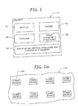
- Figure 1 is an illustration of an aircraft.
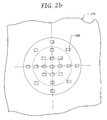
- Figures 2a and 2b are illustrations of different patterns of communication devices for providing lightning strike detection coverage of an aircraft.
- Figure 3 is an illustration of a communication device that is surface mounted to an aircraft structure.
- Figure 4 is an illustration of a communication device that is embedded in an aircraft structure.
- Figure 5 is an illustration of a communication device carried by aircraft appliqué.
- Figure 6 is an illustration of a method of detecting a lightning strike.
- Figure 7 is an illustration of a wireless communication device.
- Figure 1 illustrates an aircraft 110 having a plurality of composite structures.
- Some composite structures may be made entirely from a composite material such as fiberglass or carbon fiber reinforced plastic (CFRP).
- CFRP carbon fiber reinforced plastic
- Other structures might be a combination of composite materials and metals.
- a composite structure might include composite material, metal fasteners, electrical bonding jumpers, and metal for lightning strike protection.
- Some of the composite structures on the aircraft are more susceptible to lightning strikes than others.
- some of the most susceptible structures include nacelles 120, tips 130 of wings and vertical and horizontal stabilizers, and radomes 140.
- the aircraft's fuselage 150 and other structures 160 might also be highly susceptible.
- a lightning strike might attach and detach at separate locations of the aircraft 110, and the lightning current may travel down an LSP path or follow an unpredictable path that might be hidden or might not be apparent through visual inspection.
- FIG. 2a illustrates a plurality of small lightweight pollable communications devices 220 for providing lightning strike detection coverage of a region 210 of a susceptible structure.
- Each device 220 is rendered inoperative if struck by lightning or proximate to a lightning strike. If during a thunderstorm one of the devices 220 is rendered inoperative, lightning current in the region 210 can be assumed. If a path of devices 220 is rendered inoperative, not only can lightning current in the region 210 be assumed, but a possible path of the current can be identified.
- Operability of a device 220 can be determined by polling it. For instance, a device 220 connected to and communicating over a network could be polled by pinging it. An operable device 220 will respond to the ping. A device 220 that is blown or overpowered will not respond.
- Devices 220 connected to a wired bus may be polled simply by reading a "status discrete value" (e.g., operative / inoperative) from the device. As the discrete value would always be available to a polling process, there would be no need to wait for a response from such a polled device 220.
- a "status discrete value” e.g., operative / inoperative
- the devices 220 may be arranged in a pattern.
- a region 210 may be covered by devices 220 arranged in a grid pattern such as the grid pattern illustrated in Figure 2a , or a radial pattern such as the radial pattern illustrated in Figure 2b (the concentric circles in Figure 2b are for reference only), or some other repeatable pattern.
- the pattern is not limited to a repeatable pattern. Irregular asymmetric or other non-repeatable "random" patterns may be used, for instance for installations which have high geometrical complexity or other surface constraints or where varying levels of coverage resolution are desired.
- a region 210 may cover an entire structure or only a portion of a structure.
- the grid pattern of Figure 2a may be used to cover the tips of wings, while the radial pattern of Figure 2b may be used to provide coverage for the tip of a radome (looking head-on towards the aircraft).
- More than one structure may be covered by the communication devices 220.
- Multiple regions of a structure may be covered by the communication devices 220. Structures that are susceptible to a lightning strike may be covered, and structures that are not susceptible to a lightning strike may also be covered.
- Density of the devices 220 in a region 210 refers to the number of devices 220 distributed per unit area.
- the number of devices 220 per unit area might depend on factors such as cost and weight of adding the devices, criticality of structure, likelihood of lightning attaching or detaching (that is, susceptibility to a lightning strike), desired resolution, redundancy, etc.
- the devices 220 may use components found in a radio frequency identification (RFID) device.
- RFID radio frequency identification
- a simple device 220 may only provide identification (e.g., ID number) or some other rudimentary information (e.g., location, model number, installation date, part number of monitored aircraft structural component, or security encryption or authentication key) when polled.
- all devices 220 in a region 210 may have the same threshold to a lightning strike. That is, all devices 220 will fail at a certain threshold.
- different devices 220 may have different thresholds. That is, some devices 220 may be able to withstand higher magnitude current. For example, a single device 220 having a high threshold is surrounded by devices 220 having a low threshold. If the surrounding devices are destroyed by lightning current, but the device having the high threshold is still operable, then the lightning strike can be assumed to have had a magnitude between the high and low thresholds. By interspersing such devices 220 with different thresholds, directionality or gradients of the current magnitude may be determined.
- Thresholds of the devices 220 may be varied in a number of ways. As a first example, a range of conductive coatings can be applied to the surfaces to which the devices 220 are mounted. As a second example, different devices 220 may have different transient suppressor diodes for protection against high voltage.
- the devices 220 can be wired together.
- the devices 220 can be connected to a wired bus that runs near a surface of the aircraft.
- the devices 220 can be polled by an onboard computer that is connected to the wired bus.
- a non-safety critical maintenance computer or other such dedicated computer may poll the devices 220, and then interface with a flight computer or other onboard computer.
- the wired bus may also be used to provide electrical power to the devices 220, such as may be needed for local device data storage, processing, and/or data input and output.
- Wired buses have inherent problems. For instance, lightning current could flow through a wired bus instead of an LSP conductor. In that event, the wired bus could inadvertently facilitate the transport of the lightning-induced current to other portions of the aircraft. In addition, a string of devices 220 could be destroyed by the lightning current. These destroyed devices 220 would have to be replaced.
- Wired buses have other inherent problems.
- the wired bus could create electromagnetic interference (EMI) issues with other onboard systems.
- the wired bus could be destroyed by lightning current, whereby the devices 220 could not be polled. Wireless devices avoid these inherent problems.
- the wireless device 710 includes a processor 720, antenna 730, memory 740 and transmitter/receiver 750.
- the memory 740 can be programmed with unique identification information.
- the device 710 transmits unique identification information when polled by a polling device (e.g., an RFID reader).
- the polling device performs the polling by sending radio waves containing commands.
- the wireless device 710 may be a small, lightweight and inexpensive RFID tag.
- Conventional RFID tags are expected to fail when they are proximate to the current produced by a lightning strike (in a conventional RFID tag, the typical maximum voltage to any RFID pin is only 1.5 volts and maximum allowable current is only about 1.5 milliamps).
- RFID tags generally have built-in diodes for protection against body capacitance (static electricity), nearby passage of lightning current will likely cause the tag to fail.
- Wireless devices 710 such as RFID devices or other passive devices can be powered by energy harvesting (e.g., electromagnetic, vibration, thermal) techniques.
- a passive RFID tag uses energy from the radio waves to electrically power up and transmit a response (e.g., supply the unique identification information) to the polling device's commands.
- Wireless devices such as RFID tags are not limited to any specific operating frequency.
- Low frequency RFID tags typically operate in the 120-134 kHz range.
- High frequency RFID tags typically operate at 13.56 MHz.
- the wireless devices may even operate at ultra high frequencies, typically in the range of 850-960 MHz.
- Wireless devices offer other advantages. They are small and lightweight. They are non-contact, and don't need a line of sight. And, because wires are not needed, the wireless devices can be added without adding measurable weight to an aircraft (which increases fuel costs and emissions). Moreover, the wireless devices are electrically isolated, and they can be added to locations where wires might not be able to run. Wireless devices can communicate directly with a flight computer instead of an intermediary (e.g., a non-safety critical computer).
- an intermediary e.g., a non-safety critical computer
- the wireless devices 710 may be passive. An advantage of passive devices is that they don't need battery power. However, in some embodiments, the wireless devices 710 may be battery-powered.
- Wireless communication devices could be polled in flight by an onboard computer. Wireless communication device can also be polled on the ground by a handheld device or other fixed or portable ground device.
- a communication device may be mounted to a composite structure in a variety of ways. Different examples of mounting a communication device are illustrated in Figures 3-5 .
- a wireless communication device 310 that is surface mounted to a structure (e.g., skin, structural spar, stringer) 320.
- a wireless device 310 may be attached to a structure 320 by a sealant, epoxy, or a pressure sensitive adhesive that is temperature-cured or light-cured.
- a wireless device 310 manufactured to a rigid substrate may be attached to a structural element 320 with fasteners.
- Such a fastener may be made of a nonconductive material (e.g. nylon), or it may be made of a conductive material (e.g., metal) but have a good conductive path away from it.
- a wireless device 310 manufactured to a rigid or flexible substrate may be attached to a structure 320 with adhesive tape.
- Top coating e.g. paint or other protective covering
- FIG 4 illustrates a wireless device such as an RFID tag 410 that is embedded in a composite structure such as a composite skin 420.
- Such an RFID tag 410 can withstand a standard cure cycle. Tests have verified read/write capability of an RFID tag 410 following 220°F autoclave fiberglass panel curing temperatures. Tests have also verified that such an embedded RFID tag 410 would pass non-destructive inspection (NDI) testing (e.g., the tag 410 won't appear as a disbond or delamination).
- NDI non-destructive inspection
- FIG. 5 illustrates a communication device 510 that is carried by appliqué 520.
- Appliqué which typically has a thickness between 2-4 mils, provides a protective coating for composite structures such as fuselage skin, and wing skin (in lieu of paints and other coatings).
- the wireless device 510 may be surface mounted to the appliqué 520.
- the appliqué is then attached to a surface of a composite structure 530 using, for example, epoxy, sealant, pressure sensitive adhesive, temperature-cured adhesive, or light-cured adhesive.
- the mounting approaches of Figures 3-5 may be applied to a composite structure.
- the mounting approaches of Figures 3 and 5 may be applied to a metal structure.
- Communication devices could be installed by suppliers prior to shipping to an airframe integrator. Communication devices could be installed by an airframe integrator. Communication devices could be installed by private airlines, commercial airlines, military aircraft operators, individual aircraft operators, and maintenance providers.
- Lightning strike detection described herein can be automated, and it can be performed quickly and inexpensively. A quick diagnosis can be made without any advance knowledge of the location of a lightning strike.
- the lightning strike detection can be performed in-flight or on the ground.
- in-flight detection is that an aircraft capable of performing in-flight NDI can assess the structural health immediately after a lightning strike.
- FIG. 6 illustrates a method for assessing the structural health of an aircraft.
- polling is performed on a plurality of devices that cover a region of the aircraft.
- the polling can be performed periodically or in response to an event (e.g., a lightning strike), or both. All operative devices will respond to the polling by, for example, providing identification information.
- inoperative devices are identified. That is, those devices not responding to the polling are identified.
- locations of any inoperative devices are identified.
- the locations may be identified by accessing a lookup table of that returns a specific aircraft installation location in response to a unique device.
- analysis of an affected region is performed to identify inspection zones. Inspection zones will be examined in greater detail by NDI. At a minimum, the analysis may indicate whether the region under test was struck by lightning. If multiple devices are inoperative, the analysis may also suggest a path followed by the current, where the lightning detached, magnitude of the lightning strike, etc. In some embodiments, the analysis may indicate whether LSP failed.
- More sophisticated analysis may link the IDs of failed devices with a record of actual installed location, and display a geometric representation of the aircraft, device installation, and damage path based on lack of device response.
- the analysis may include all information stored on the failed device (e.g. installation date, device model number, etc.) as well as act as the programming interface to write a unique ID to a given newly installed tag.
- the analysis may also be linked in to a historical trending database, or other, for comparison of damage across multiple aircraft.
- nondestructive inspection for damage caused by the lightning strike is performed on any inspection zones.
- ultrasonic testing or infrared spectroscopy may be performed on an inspection zone.
- the method of Figure 6 allows NDI to be localized quickly, without any advance knowledge of the lightning strike. Very large areas of an aircraft structure do not have to be inspected, and specific indicators (e.g., areas containing surface pitting and paint damage) are far less likely to be missed.
- the functions at block 610- 640 may be performed in-flight. If the aircraft can perform in-flight NDI, the function at block 650 may also be performed in-flight. Lightning strike detection results may be sent to a computer that is on-board the aircraft, and/or it may be transmitted to a computer that is on the ground. If a lightning strike is detected, an appropriate action is taken. As a first example, a pilot is notified that the aircraft has been struck by lightning and the region that has been struck. If the aircraft can perform in-flight NDI, it could inspect any inspection zones and inform the pilot of any damage. A recommendation can then be made as to aborting or continuing the flight.
- NDI could be performed by a ground crew after the aircraft has landed, or it could be performed later by a vehicle health maintenance service (VHMS). Once the aircraft is on the ground, additional NDI could be performed using conventional techniques.
- VHMS vehicle health maintenance service
- Lightning strike detection described herein can also reduce an airline's maintenance costs and eliminate the need to abort flights for non-critical problems.
- inoperative devices can be replaced by maintenance personnel. If an inoperative device was surface mounted, it can be removed, and a replacement device can be surface mounted to the same location. If an inoperative device is embedded, a replacement device can be surface mounted to the location over the inoperative device.
- Lightning strike detection described herein is not limited to composite aircraft.
- the lightning strike detection can also be applied to metal structures.
- the detection could also identify problems caused by lightning strikes on metal aircraft. For example, lightning-related problems could be identified in aircraft avionics systems.
- Lightning strike detection described herein is not limited to aircraft.
- the lightning strike detection could be applied to other systems including, but not limited to, spacecraft and wind turbines.
- Another application is for monitoring critical junctions in electrical power feeders for power networks.
- high currents from lightning-induced overvoltages would travel along the power lines to any equipment powered by the lines, possible paths of transient surges due to direct effects of lightning strikes can be isolated to a subset of the number of branches in a multi-branch power distribution network.
- RFID tags positioned at intervals along the power lines (e.g., encased within an environmental protection enclosure and attached to the critical wire or junction) with varying detection thresholds, surge magnitudes could be determined.
- Electrical power utility company personnel could use RFID tag readers and simply drive by power lines equipped with such RFID tags to determine the path and/or extent of transient surge.
- Detection described herein is not limited to lightning strike detection. Lighting is an electromagnetic effect (EME). More generally, the detection described herein can be applied to the detection of EME. A plurality of wireless communication devices arranged on a region of a body can be used to detect effects of EME on that region. Further, the invention comprises embodiments according to the following clauses:
Landscapes
- Engineering & Computer Science (AREA)
- Aviation & Aerospace Engineering (AREA)
- Physics & Mathematics (AREA)
- Electromagnetism (AREA)
- General Physics & Mathematics (AREA)
- Arrangements For Transmission Of Measured Signals (AREA)
- Elimination Of Static Electricity (AREA)
- Insulators (AREA)
Abstract
Description
- General aviation aircraft and large commercial jets are vulnerable to lightning strike. Unlike their metal counterparts, composite structures in these aircraft do not readily conduct away the extreme electrical currents and electromagnetic forces generated by lightning strikes.
- Aircraft with composite structures may be equipped with lightning strike protection (LSP). For example, conductive media may be provided on a surface or in a structure to divert and distribute lightning current.
- A problem exists with determining whether lightning current has traveled through a particular region of an aircraft. A lightning strike might attach and detach at separate locations, and the lightning current might follow LSP paths or unpredictable paths therebetween. As but one example, lightning might attach at the nose of the fuselage, follow paths toward the aft of the fuselage, and detach at a random location on a horizontal stabilizer. Damage to composite material can occur at the locations of lightning attachment and detachment. Damage to composite material can also occur along paths taken by the lightning current.
- The damage caused by a lightning strike might be hidden, or it might not be apparent through visual inspection. To detect damage caused by a lightning strike, very large areas of an aircraft structure might have to be examined. However, non-destructive inspection (NDI) on very large areas is time-consuming and expensive. Moreover, specific areas (e.g., areas containing surface pitting and paint damage) can be missed if a very large area has to be inspected.
- According to an embodiment of the present invention, an aircraft includes a composite structure and a plurality of small lightweight pollable communication devices for providing lightning strike detection coverage of a region of the structure. Each device is rendered inoperative if at least proximate to lightning current.
- According to another embodiment, a structure that will be susceptible to electromagnetic effects includes a body, and a plurality of RFID tags mounted to the body for providing EME detection of the structure. Each tag is rendered inoperative if at least proximate to EME current.
- According to another embodiment, a method of analyzing structural health of an aircraft includes interrogating a plurality of communication devices that cover a region of the aircraft, identifying those devices that are inoperative, and identifying any inspection zones from the inoperative devices.
-
Figure 1 is an illustration of an aircraft. -
Figures 2a and2b are illustrations of different patterns of communication devices for providing lightning strike detection coverage of an aircraft. -
Figure 3 is an illustration of a communication device that is surface mounted to an aircraft structure. -
Figure 4 is an illustration of a communication device that is embedded in an aircraft structure. -
Figure 5 is an illustration of a communication device carried by aircraft appliqué. -
Figure 6 is an illustration of a method of detecting a lightning strike. -
Figure 7 is an illustration of a wireless communication device. - Reference is made to
Figure 1 , which illustrates anaircraft 110 having a plurality of composite structures. Some composite structures may be made entirely from a composite material such as fiberglass or carbon fiber reinforced plastic (CFRP). Other structures might be a combination of composite materials and metals. For example, a composite structure might include composite material, metal fasteners, electrical bonding jumpers, and metal for lightning strike protection. - Some of the composite structures on the aircraft are more susceptible to lightning strikes than others. On a large commercial aircraft, some of the most susceptible structures include
nacelles 120,tips 130 of wings and vertical and horizontal stabilizers, andradomes 140. The aircraft'sfuselage 150 andother structures 160 might also be highly susceptible. - A lightning strike might attach and detach at separate locations of the
aircraft 110, and the lightning current may travel down an LSP path or follow an unpredictable path that might be hidden or might not be apparent through visual inspection. - Reference is made to
Figure 2a , which illustrates a plurality of small lightweightpollable communications devices 220 for providing lightning strike detection coverage of aregion 210 of a susceptible structure. Eachdevice 220 is rendered inoperative if struck by lightning or proximate to a lightning strike. If during a thunderstorm one of thedevices 220 is rendered inoperative, lightning current in theregion 210 can be assumed. If a path ofdevices 220 is rendered inoperative, not only can lightning current in theregion 210 be assumed, but a possible path of the current can be identified. - Operability of a
device 220 can be determined by polling it. For instance, adevice 220 connected to and communicating over a network could be polled by pinging it. Anoperable device 220 will respond to the ping. Adevice 220 that is blown or overpowered will not respond. -
Devices 220 connected to a wired bus may be polled simply by reading a "status discrete value" (e.g., operative / inoperative) from the device. As the discrete value would always be available to a polling process, there would be no need to wait for a response from such apolled device 220. - The
devices 220 may be arranged in a pattern. Aregion 210 may be covered bydevices 220 arranged in a grid pattern such as the grid pattern illustrated inFigure 2a , or a radial pattern such as the radial pattern illustrated inFigure 2b (the concentric circles inFigure 2b are for reference only), or some other repeatable pattern. The pattern is not limited to a repeatable pattern. Irregular asymmetric or other non-repeatable "random" patterns may be used, for instance for installations which have high geometrical complexity or other surface constraints or where varying levels of coverage resolution are desired. - A
region 210 may cover an entire structure or only a portion of a structure. For example, the grid pattern ofFigure 2a may be used to cover the tips of wings, while the radial pattern ofFigure 2b may be used to provide coverage for the tip of a radome (looking head-on towards the aircraft). More than one structure may be covered by thecommunication devices 220. Multiple regions of a structure may be covered by thecommunication devices 220. Structures that are susceptible to a lightning strike may be covered, and structures that are not susceptible to a lightning strike may also be covered. - "Density" of the
devices 220 in aregion 210 refers to the number ofdevices 220 distributed per unit area. The number ofdevices 220 per unit area might depend on factors such as cost and weight of adding the devices, criticality of structure, likelihood of lightning attaching or detaching (that is, susceptibility to a lightning strike), desired resolution, redundancy, etc. - The
devices 220 may use components found in a radio frequency identification (RFID) device. Asimple device 220 may only provide identification (e.g., ID number) or some other rudimentary information (e.g., location, model number, installation date, part number of monitored aircraft structural component, or security encryption or authentication key) when polled. - In some embodiments, all
devices 220 in aregion 210 may have the same threshold to a lightning strike. That is, alldevices 220 will fail at a certain threshold. - In other embodiments, however,
different devices 220 may have different thresholds. That is, somedevices 220 may be able to withstand higher magnitude current. For example, asingle device 220 having a high threshold is surrounded bydevices 220 having a low threshold. If the surrounding devices are destroyed by lightning current, but the device having the high threshold is still operable, then the lightning strike can be assumed to have had a magnitude between the high and low thresholds. By interspersingsuch devices 220 with different thresholds, directionality or gradients of the current magnitude may be determined. - Thresholds of the
devices 220 may be varied in a number of ways. As a first example, a range of conductive coatings can be applied to the surfaces to which thedevices 220 are mounted. As a second example,different devices 220 may have different transient suppressor diodes for protection against high voltage. - The
devices 220 can be wired together. For example, thedevices 220 can be connected to a wired bus that runs near a surface of the aircraft. Thedevices 220 can be polled by an onboard computer that is connected to the wired bus. For example, a non-safety critical maintenance computer or other such dedicated computer may poll thedevices 220, and then interface with a flight computer or other onboard computer. The wired bus may also be used to provide electrical power to thedevices 220, such as may be needed for local device data storage, processing, and/or data input and output. - Wired buses have inherent problems. For instance, lightning current could flow through a wired bus instead of an LSP conductor. In that event, the wired bus could inadvertently facilitate the transport of the lightning-induced current to other portions of the aircraft. In addition, a string of
devices 220 could be destroyed by the lightning current. These destroyeddevices 220 would have to be replaced. - Wired buses have other inherent problems. The wired bus could create electromagnetic interference (EMI) issues with other onboard systems. The wired bus could be destroyed by lightning current, whereby the
devices 220 could not be polled. Wireless devices avoid these inherent problems. - Reference is made to
Figure 7 , which illustrates an example of awireless communication device 710. Thewireless device 710 includes aprocessor 720,antenna 730,memory 740 and transmitter/receiver 750. Thememory 740 can be programmed with unique identification information. Thedevice 710 transmits unique identification information when polled by a polling device (e.g., an RFID reader). The polling device performs the polling by sending radio waves containing commands. - The
wireless device 710 may be a small, lightweight and inexpensive RFID tag. Conventional RFID tags are expected to fail when they are proximate to the current produced by a lightning strike (in a conventional RFID tag, the typical maximum voltage to any RFID pin is only 1.5 volts and maximum allowable current is only about 1.5 milliamps). Though RFID tags generally have built-in diodes for protection against body capacitance (static electricity), nearby passage of lightning current will likely cause the tag to fail. -
Wireless devices 710 such as RFID devices or other passive devices can be powered by energy harvesting (e.g., electromagnetic, vibration, thermal) techniques. A passive RFID tag uses energy from the radio waves to electrically power up and transmit a response (e.g., supply the unique identification information) to the polling device's commands. - Wireless devices such as RFID tags are not limited to any specific operating frequency. Low frequency RFID tags typically operate in the 120-134 kHz range. High frequency RFID tags typically operate at 13.56 MHz. The wireless devices may even operate at ultra high frequencies, typically in the range of 850-960 MHz.
- Wireless devices offer other advantages. They are small and lightweight. They are non-contact, and don't need a line of sight. And, because wires are not needed, the wireless devices can be added without adding measurable weight to an aircraft (which increases fuel costs and emissions). Moreover, the wireless devices are electrically isolated, and they can be added to locations where wires might not be able to run. Wireless devices can communicate directly with a flight computer instead of an intermediary (e.g., a non-safety critical computer).
- The
wireless devices 710 may be passive. An advantage of passive devices is that they don't need battery power. However, in some embodiments, thewireless devices 710 may be battery-powered. - Wireless communication devices could be polled in flight by an onboard computer. Wireless communication device can also be polled on the ground by a handheld device or other fixed or portable ground device.
- A communication device may be mounted to a composite structure in a variety of ways. Different examples of mounting a communication device are illustrated in
Figures 3-5 . - Reference is made to
Figure 3 , which illustrates awireless communication device 310 that is surface mounted to a structure (e.g., skin, structural spar, stringer) 320. In some embodiments, awireless device 310 may be attached to astructure 320 by a sealant, epoxy, or a pressure sensitive adhesive that is temperature-cured or light-cured. In some embodiments awireless device 310 manufactured to a rigid substrate may be attached to astructural element 320 with fasteners. Such a fastener may be made of a nonconductive material (e.g. nylon), or it may be made of a conductive material (e.g., metal) but have a good conductive path away from it. In some embodiments, awireless device 310 manufactured to a rigid or flexible substrate may be attached to astructure 320 with adhesive tape. - Environmental conditions for surface mounted devices may be considered for each desired installation location. Top coating (e.g. paint or other protective covering) may be considered.
- Reference is made to
Figure 4 , which illustrates a wireless device such as anRFID tag 410 that is embedded in a composite structure such as acomposite skin 420. AnRFID tag 410 having the geometry of a label, for instance, could be placed between layers (within the first few plies) of fiberglass, prior to curing the fiberglass. Such anRFID tag 410 can withstand a standard cure cycle. Tests have verified read/write capability of anRFID tag 410 following 220°F autoclave fiberglass panel curing temperatures. Tests have also verified that such an embeddedRFID tag 410 would pass non-destructive inspection (NDI) testing (e.g., thetag 410 won't appear as a disbond or delamination). - Reference is made to
Figure 5 , which illustrates acommunication device 510 that is carried byappliqué 520. Appliqué, which typically has a thickness between 2-4 mils, provides a protective coating for composite structures such as fuselage skin, and wing skin (in lieu of paints and other coatings). Thewireless device 510 may be surface mounted to theappliqué 520. The appliqué is then attached to a surface of acomposite structure 530 using, for example, epoxy, sealant, pressure sensitive adhesive, temperature-cured adhesive, or light-cured adhesive. - The mounting approaches of
Figures 3-5 may be applied to a composite structure. The mounting approaches ofFigures 3 and 5 may be applied to a metal structure. - Communication devices could be installed by suppliers prior to shipping to an airframe integrator. Communication devices could be installed by an airframe integrator. Communication devices could be installed by private airlines, commercial airlines, military aircraft operators, individual aircraft operators, and maintenance providers.
- Lightning strike detection described herein can be automated, and it can be performed quickly and inexpensively. A quick diagnosis can be made without any advance knowledge of the location of a lightning strike.
- Moreover, the lightning strike detection can be performed in-flight or on the ground. One advantage of in-flight detection is that an aircraft capable of performing in-flight NDI can assess the structural health immediately after a lightning strike.
- Reference is now made to
Figure 6 , which illustrates a method for assessing the structural health of an aircraft. Atblock 610, polling is performed on a plurality of devices that cover a region of the aircraft. The polling can be performed periodically or in response to an event (e.g., a lightning strike), or both. All operative devices will respond to the polling by, for example, providing identification information. - At
block 620, inoperative devices are identified. That is, those devices not responding to the polling are identified. - At
block 630, locations of any inoperative devices are identified. The locations may be identified by accessing a lookup table of that returns a specific aircraft installation location in response to a unique device. - At
block 640, analysis of an affected region is performed to identify inspection zones. Inspection zones will be examined in greater detail by NDI. At a minimum, the analysis may indicate whether the region under test was struck by lightning. If multiple devices are inoperative, the analysis may also suggest a path followed by the current, where the lightning detached, magnitude of the lightning strike, etc. In some embodiments, the analysis may indicate whether LSP failed. - More sophisticated analysis may link the IDs of failed devices with a record of actual installed location, and display a geometric representation of the aircraft, device installation, and damage path based on lack of device response. The analysis may include all information stored on the failed device (e.g. installation date, device model number, etc.) as well as act as the programming interface to write a unique ID to a given newly installed tag. The analysis may also be linked in to a historical trending database, or other, for comparison of damage across multiple aircraft.
- At
block 650, nondestructive inspection for damage caused by the lightning strike is performed on any inspection zones. For example, ultrasonic testing or infrared spectroscopy may be performed on an inspection zone. - Thus, the method of
Figure 6 allows NDI to be localized quickly, without any advance knowledge of the lightning strike. Very large areas of an aircraft structure do not have to be inspected, and specific indicators (e.g., areas containing surface pitting and paint damage) are far less likely to be missed. - The functions at block 610- 640 may be performed in-flight. If the aircraft can perform in-flight NDI, the function at
block 650 may also be performed in-flight. Lightning strike detection results may be sent to a computer that is on-board the aircraft, and/or it may be transmitted to a computer that is on the ground. If a lightning strike is detected, an appropriate action is taken. As a first example, a pilot is notified that the aircraft has been struck by lightning and the region that has been struck. If the aircraft can perform in-flight NDI, it could inspect any inspection zones and inform the pilot of any damage. A recommendation can then be made as to aborting or continuing the flight. - As a second example, if the lightning strike detection indicates that a region was struck by lightning, NDI could be performed by a ground crew after the aircraft has landed, or it could be performed later by a vehicle health maintenance service (VHMS). Once the aircraft is on the ground, additional NDI could be performed using conventional techniques.
- The in-flight testing increases aircraft safety. Lightning strike detection described herein can also reduce an airline's maintenance costs and eliminate the need to abort flights for non-critical problems.
- At
block 660, once the aircraft is on the ground, structural damage can be fully assessed, and damaged structures can be repaired. In addition, inoperative devices can be replaced by maintenance personnel. If an inoperative device was surface mounted, it can be removed, and a replacement device can be surface mounted to the same location. If an inoperative device is embedded, a replacement device can be surface mounted to the location over the inoperative device. - Lightning strike detection described herein is not limited to composite aircraft. The lightning strike detection can also be applied to metal structures. The detection could also identify problems caused by lightning strikes on metal aircraft. For example, lightning-related problems could be identified in aircraft avionics systems.
- Lightning strike detection described herein is not limited to aircraft. The lightning strike detection could be applied to other systems including, but not limited to, spacecraft and wind turbines.
- Another application is for monitoring critical junctions in electrical power feeders for power networks.. As high currents from lightning-induced overvoltages would travel along the power lines to any equipment powered by the lines, possible paths of transient surges due to direct effects of lightning strikes can be isolated to a subset of the number of branches in a multi-branch power distribution network. By using RFID tags positioned at intervals along the power lines (e.g., encased within an environmental protection enclosure and attached to the critical wire or junction) with varying detection thresholds, surge magnitudes could be determined. Electrical power utility company personnel could use RFID tag readers and simply drive by power lines equipped with such RFID tags to determine the path and/or extent of transient surge.
- Detection described herein is not limited to lightning strike detection. Lighting is an electromagnetic effect (EME). More generally, the detection described herein can be applied to the detection of EME. A plurality of wireless communication devices arranged on a region of a body can be used to detect effects of EME on that region.
Further, the invention comprises embodiments according to the following clauses: - Clause 1. An aircraft comprising:
- a composite structure (120, 130, 140, 150, 160);
- a plurality of small lightweight pollable communication devices (220) for providing lightning strike detection coverage of a region of the structure, each device rendered inoperative if at least proximate to lightning current.
- Clause 2. The aircraft of clause 1, wherein the structure is of one of a nacelle (120), a radome (140) a wing tip (130), a horizontal stabilizer tip (130), and a vertical stabilizer tip (130).
- Clause 3. The aircraft of clause 1 or 2, wherein the devices are arranged in a repeating pattern that allows damage by lightning current to be localized.
- Clause 4. The aircraft of any of the preceding clauses, wherein operable devices only provide identification information when polled.
- Clause 5. The aircraft of any of the preceding clauses, wherein at least some of the devices (220) have different current and voltage thresholds so directionality or gradients of strike magnitude can be determined.
- Clause 6. The aircraft of any of the preceding clauses, wherein the devices (220) are wireless devices.
- Clause 7. The aircraft of any of the preceding clauses, wherein the devices (220) are RFID tags.
- Clause 8. The aircraft of any of the preceding clauses, wherein at least some of the devices (220) are surface mounted to the composite structure.
- Clause 9. The aircraft of any of the preceding clauses, wherein at least some of the devices (220) are embedded in the composite structure.
- Clause 10. The aircraft of any of the preceding clauses, wherein at least some of the devices (220) are carried by an appliqué on the composite structure.
- Clause 11. A method of detecting lightning strike paths on an aircraft (110), the method comprising:
- interrogating a plurality of communication devices (220) that cover a region of the aircraft;
- identifying those devices that are inoperative; and
- identifying any inspection zones from the inoperative devices.
- Clause 12. The method of clause 11, further comprising performing non-destructive inspection on any inspection zones for damage caused by lightning current.
- Clause 13. The method of clause 11 or 12, wherein an inspection zone includes at least one of a lightning attachment location, a lightning detachment location, and a location along a path taken by lightning current.
- Clause 14. The method of any of clauses 11 to 13, wherein the inspection zone is identified in-flight.
- Clause 15. The method of any of clauses 11 to 14, wherein the inspection zone is identified on-ground.
Claims (14)
- An aircraft comprising:a composite structure (120, 130, 140, 150, 160);a plurality of small lightweight pollable communication devices (220) for providing lightning strike detection coverage of a region of the structure, each device rendered inoperative if at least proximate to lightning current, characterized in that the devices are arranged in a repeating pattern that allows damage by lightning current to be localized.
- The aircraft of claim 1, wherein the structure is of one of a nacelle (120), a radome (140) a wing tip (130), a horizontal stabilizer tip (130), and a vertical stabilizer tip (130).
- The aircraft of any of the preceding claims, wherein operable devices only provide identification information when polled.
- The aircraft of any of the preceding claims, wherein at least some of the devices (220) have different current and voltage thresholds so directionality or gradients of strike magnitude can be determined.
- The aircraft of any of the preceding claims, wherein the devices (220) are wireless devices.
- The aircraft of any of the preceding claims, wherein the devices (220) are RFID tags.
- The aircraft of any of the preceding claims, wherein at least some of the devices (220) are surface mounted to the composite structure.
- The aircraft of any of the preceding claims, wherein at least some of the devices (220) are embedded in the composite structure.
- The aircraft of any of the preceding claims, wherein at least some of the devices (220) are carried by an appliqué on the composite structure.
- A method of detecting lightning strike paths on an aircraft (110), the method comprising:interrogating a plurality of communication devices (220) that cover a region of the aircraft, wherein the devices are arranged in a repeating pattern that allows damage by lightning current to be localized;identifying those devices that are inoperative; andidentifying any inspection zones from the inoperative devices.
- The method of claim 10, further comprising performing non-destructive inspection on any inspection zones for damage caused by lightning current.
- The method of claim 10 or 11, wherein an inspection zone includes at least one of a lightning attachment location, a lightning detachment location, and a location along a path taken by lightning current.
- The method of any of claims 10 to 12, wherein the inspection zone is identified in-flight.
- The method of any of claims 10 to 13, wherein the inspection zone is identified on-ground.
Applications Claiming Priority (2)
| Application Number | Priority Date | Filing Date | Title |
|---|---|---|---|
| US12/052,618 US8878698B2 (en) | 2008-03-20 | 2008-03-20 | Lightning strike detection |
| EP09155362A EP2103517B1 (en) | 2008-03-20 | 2009-03-17 | Lightning strike detection |
Related Parent Applications (1)
| Application Number | Title | Priority Date | Filing Date |
|---|---|---|---|
| EP09155362.8 Division | 2009-03-17 |
Publications (2)
| Publication Number | Publication Date |
|---|---|
| EP2479110A1 true EP2479110A1 (en) | 2012-07-25 |
| EP2479110B1 EP2479110B1 (en) | 2013-05-08 |
Family
ID=40585498
Family Applications (2)
| Application Number | Title | Priority Date | Filing Date |
|---|---|---|---|
| EP09155362A Active EP2103517B1 (en) | 2008-03-20 | 2009-03-17 | Lightning strike detection |
| EP12164469.4A Active EP2479110B1 (en) | 2008-03-20 | 2009-03-17 | Lightning strike detection |
Family Applications Before (1)
| Application Number | Title | Priority Date | Filing Date |
|---|---|---|---|
| EP09155362A Active EP2103517B1 (en) | 2008-03-20 | 2009-03-17 | Lightning strike detection |
Country Status (9)
| Country | Link |
|---|---|
| US (1) | US8878698B2 (en) |
| EP (2) | EP2103517B1 (en) |
| JP (1) | JP5437673B2 (en) |
| KR (1) | KR101549706B1 (en) |
| CN (1) | CN101602408B (en) |
| AU (1) | AU2009200830B2 (en) |
| CA (1) | CA2655489C (en) |
| ES (1) | ES2424478T3 (en) |
| RU (1) | RU2501719C2 (en) |
Families Citing this family (21)
| Publication number | Priority date | Publication date | Assignee | Title |
|---|---|---|---|---|
| US8886388B2 (en) | 2009-06-29 | 2014-11-11 | The Boeing Company | Embedded damage detection system for composite materials of an aircraft |
| US8427333B2 (en) * | 2009-06-29 | 2013-04-23 | General Electric Company | System and method for detecting lightning |
| GB201008183D0 (en) * | 2010-05-10 | 2010-06-30 | Vestas Wind Sys As | Method for producing a wind turbine component having wireless devices embedded therein |
| US8327710B2 (en) | 2010-07-29 | 2012-12-11 | General Electric Company | System for estimating a condition of non-conductive hollow structure exposed to a lightning strike |
| US8823554B2 (en) * | 2010-12-09 | 2014-09-02 | The Boeing Company | Managing a plurality of radio frequency identification devices |
| US9217811B1 (en) * | 2011-12-15 | 2015-12-22 | The Boeing Company | Lightning damage index |
| US8258773B2 (en) * | 2011-06-09 | 2012-09-04 | General Electric Company | System for detecting lightning strikes on wind turbine rotor blades |
| US9523761B1 (en) * | 2014-02-21 | 2016-12-20 | Rockwell Collins, Inc. | Geolocation with redundant aircraft antennas system and related method |
| EP3117098B1 (en) * | 2014-03-06 | 2019-10-02 | Global Lightning Protection Services A/S | Lightning measuring system for a wind turbine |
| CN105403778B (en) * | 2015-09-17 | 2019-08-02 | 西安交通大学 | A measurement method and system for multi-loop timing work |
| US9939358B2 (en) * | 2015-09-24 | 2018-04-10 | The Boeing Company | Sealant testing for aircraft fuel tanks |
| FR3051442B1 (en) * | 2016-05-20 | 2021-07-16 | Airbus Operations Sas | ON-BOARD SYSTEM FOR EVALUATING THE SEVERITY OF A LIGHTNING STRIKE |
| ES2783623T3 (en) * | 2016-07-18 | 2020-09-17 | Airbus Operations Sl | Method and device for the inspection of damage to the skin of an aircraft after a lightning strike |
| CN106501623B (en) * | 2016-11-03 | 2019-06-14 | 山东农业大学 | Multi-rotor UAV lightning strike hazard measurement device and multi-rotor UAV |
| CN106771856B (en) * | 2016-11-30 | 2020-01-03 | 国网河南省电力公司滑县供电公司 | Electric power transmission line lightning stroke point determination method based on unmanned aerial vehicle technology |
| US10501202B2 (en) * | 2017-08-23 | 2019-12-10 | The Boeing Company | Ignition-quenching systems, apparatuses, and methods |
| US11953953B2 (en) * | 2018-09-27 | 2024-04-09 | The Boeing Company | Behind the radome mounting system for aircraft avionics equipment |
| CN109598069B (en) * | 2018-12-06 | 2022-12-13 | 西安交通大学 | Carbon fiber composite material lightning damage assessment method considering nonlinear impedance characteristics |
| KR102312376B1 (en) * | 2020-05-28 | 2021-10-13 | 국방과학연구소 | Structure of returen conductor for full vehicle lightning test |
| CN113011098B (en) * | 2021-03-26 | 2023-09-01 | 云南电网有限责任公司电力科学研究院 | A model and system for analysis and display of lightning activity law in transmission corridor area |
| CN113778124A (en) * | 2021-09-01 | 2021-12-10 | 万航星空科技发展有限公司 | A 5G-based UAV video transmission system and method |
Citations (3)
| Publication number | Priority date | Publication date | Assignee | Title |
|---|---|---|---|---|
| US4156182A (en) * | 1976-09-13 | 1979-05-22 | The Boeing Company | Lightning strike detector |
| US7176812B1 (en) * | 2005-08-04 | 2007-02-13 | The United States Of America As Represented By The Secretary Of The Navy | Wireless blade monitoring system and process |
| US20070159346A1 (en) * | 2006-01-10 | 2007-07-12 | General Electric Company | Method and assembly for detecting blade status in a wind turbine |
Family Cites Families (13)
| Publication number | Priority date | Publication date | Assignee | Title |
|---|---|---|---|---|
| US4352142A (en) * | 1981-04-15 | 1982-09-28 | The Boeing Company | Composite aircraft structure having lightning protection |
| JP2001006080A (en) | 1999-06-23 | 2001-01-12 | Toyo Commun Equip Co Ltd | Multipoint data collection system |
| JP2002082138A (en) * | 2000-09-07 | 2002-03-22 | Ntt Advanced Technology Corp | Lightning detection sensor and distribution line entrance device |
| JP2003298660A (en) * | 2002-03-29 | 2003-10-17 | Hitachi Communication Technologies Ltd | VoIP gateway device and method for detecting VoIP communication state |
| JP3838503B2 (en) * | 2002-08-26 | 2006-10-25 | 株式会社エヌ・ティ・ティ・ドコモ | Monitoring system, monitoring target management apparatus, and monitoring method |
| US7730547B2 (en) * | 2003-01-23 | 2010-06-01 | William Marsh Rice University | Smart materials: strain sensing and stress determination by means of nanotube sensing systems, composites, and devices |
| GB2405934A (en) * | 2003-09-09 | 2005-03-16 | Qinetiq Ltd | Resistance strain/moisture gauge |
| US7867621B2 (en) * | 2003-09-30 | 2011-01-11 | The Boeing Company | Wide area lightning diverter overlay |
| JP4288584B2 (en) * | 2003-10-06 | 2009-07-01 | 中部電力株式会社 | Wire damage detector |
| CN101137841B (en) * | 2005-02-03 | 2013-01-09 | 维斯塔斯风力系统有限公司 | Method of manufacturing a wind turbine blade shell member |
| US7678997B2 (en) * | 2006-12-19 | 2010-03-16 | The Boeing Company | Large area circuitry using appliqués |
| FR2913504B1 (en) * | 2007-03-07 | 2009-04-17 | Airbus France Sas | DEVICE AND METHOD FOR DETECTING LIGHTNING IMPACTS ON A STRUCTURE OF ELECTRICALLY INSULATING MATERIAL. |
| US8202053B2 (en) * | 2008-03-19 | 2012-06-19 | General Electric Company | Micro-electromechanical current sensing apparatus |
-
2008
- 2008-03-20 US US12/052,618 patent/US8878698B2/en active Active
-
2009
- 2009-02-24 CA CA2655489A patent/CA2655489C/en active Active
- 2009-03-03 AU AU2009200830A patent/AU2009200830B2/en active Active
- 2009-03-17 EP EP09155362A patent/EP2103517B1/en active Active
- 2009-03-17 ES ES12164469T patent/ES2424478T3/en active Active
- 2009-03-17 EP EP12164469.4A patent/EP2479110B1/en active Active
- 2009-03-18 RU RU2009109742/11A patent/RU2501719C2/en active
- 2009-03-19 KR KR1020090023619A patent/KR101549706B1/en active Active
- 2009-03-19 CN CN200910128872.5A patent/CN101602408B/en active Active
- 2009-03-23 JP JP2009070618A patent/JP5437673B2/en active Active
Patent Citations (3)
| Publication number | Priority date | Publication date | Assignee | Title |
|---|---|---|---|---|
| US4156182A (en) * | 1976-09-13 | 1979-05-22 | The Boeing Company | Lightning strike detector |
| US7176812B1 (en) * | 2005-08-04 | 2007-02-13 | The United States Of America As Represented By The Secretary Of The Navy | Wireless blade monitoring system and process |
| US20070159346A1 (en) * | 2006-01-10 | 2007-07-12 | General Electric Company | Method and assembly for detecting blade status in a wind turbine |
Also Published As
| Publication number | Publication date |
|---|---|
| US20090237272A1 (en) | 2009-09-24 |
| JP2009229465A (en) | 2009-10-08 |
| JP5437673B2 (en) | 2014-03-12 |
| AU2009200830A1 (en) | 2009-10-08 |
| KR101549706B1 (en) | 2015-09-02 |
| CN101602408A (en) | 2009-12-16 |
| ES2424478T3 (en) | 2013-10-02 |
| CA2655489C (en) | 2013-10-29 |
| EP2479110B1 (en) | 2013-05-08 |
| CA2655489A1 (en) | 2009-09-20 |
| RU2501719C2 (en) | 2013-12-20 |
| RU2009109742A (en) | 2010-09-27 |
| US8878698B2 (en) | 2014-11-04 |
| KR20090101115A (en) | 2009-09-24 |
| EP2103517A3 (en) | 2011-01-19 |
| EP2103517B1 (en) | 2012-07-25 |
| EP2103517A2 (en) | 2009-09-23 |
| AU2009200830B2 (en) | 2013-08-01 |
| CN101602408B (en) | 2016-09-28 |
Similar Documents
| Publication | Publication Date | Title |
|---|---|---|
| US8878698B2 (en) | Lightning strike detection | |
| US10302524B2 (en) | Detection and assessment of damage to composite structure | |
| US9567104B2 (en) | Utilization of aircraft bondline embedded current sensors in the determination of a lightning damage index | |
| US9267906B2 (en) | Bondline embedded current sensor | |
| US8237548B2 (en) | Structural health management device and associated system and method | |
| US6900642B2 (en) | Aircraft electrostatic discharge test system | |
| US7765864B2 (en) | Device and method for detecting lightning strikes on a structure made of electrically insulating material | |
| EP2800690B1 (en) | Supercooled large drop icing condition detection system | |
| US20100094566A1 (en) | Methods, systems, and computer readable media for wireless crack detection and monitoring | |
| JP6549439B2 (en) | Wireless fuel sensor system | |
| US20250028008A1 (en) | Device, system and method for performing a continuity test of an electrical line of an object | |
| US20190077517A1 (en) | Systems and methods for detecting impacts to vehicle surfaces | |
| van't Hoff et al. | Korean utility helicopter KUH-1 icing certification program | |
| Fay et al. | Airbus lightning in service experience vs lightning zoning | |
| Czarnigowski et al. | Analysis of influence of legal requirements on the design of electronic ignition system for aviation piston engine | |
| Sweers | Methodology for the design assurance of aricraft lightning protection systems continued airworthiness | |
| Cristofani et al. | Analysis of HIRF effects in aircrafts | |
| Wallace et al. | Development of ICE/NO-ICE sensor system for in-flight ice detection | |
| Iq | COMPATIBILITY MANUAL | |
| EIRIZ et al. | CERTIFICATION PROCESS OF SHM SYSTEMS IN THE AERONAUTICAL SECTOR | |
| Rouet et al. | SAE International | |
| Lalande et al. | ALISDAR: an automatic lightning system detection and recording |
Legal Events
| Date | Code | Title | Description |
|---|---|---|---|
| PUAI | Public reference made under article 153(3) epc to a published international application that has entered the european phase |
Free format text: ORIGINAL CODE: 0009012 |
|
| AC | Divisional application: reference to earlier application |
Ref document number: 2103517 Country of ref document: EP Kind code of ref document: P |
|
| AK | Designated contracting states |
Kind code of ref document: A1 Designated state(s): AT BE BG CH CY CZ DE DK EE ES FI FR GB GR HR HU IE IS IT LI LT LU LV MC MK MT NL NO PL PT RO SE SI SK TR |
|
| RIN1 | Information on inventor provided before grant (corrected) |
Inventor name: DUCE, JEFFREY L. Inventor name: FOGARTY, MICHAEL D. Inventor name: GEORGESON, GARY E. Inventor name: CLARK, GREGORY J. |
|
| 17P | Request for examination filed |
Effective date: 20120821 |
|
| RIC1 | Information provided on ipc code assigned before grant |
Ipc: B64D 45/02 20060101AFI20120913BHEP |
|
| GRAP | Despatch of communication of intention to grant a patent |
Free format text: ORIGINAL CODE: EPIDOSNIGR1 |
|
| RIN1 | Information on inventor provided before grant (corrected) |
Inventor name: CLARK, GREGORY J. Inventor name: FOGARTY, MICHAEL D. Inventor name: DUCE, JEFFREY L. Inventor name: GEORGESON, GARY E. |
|
| GRAS | Grant fee paid |
Free format text: ORIGINAL CODE: EPIDOSNIGR3 |
|
| GRAA | (expected) grant |
Free format text: ORIGINAL CODE: 0009210 |
|
| AC | Divisional application: reference to earlier application |
Ref document number: 2103517 Country of ref document: EP Kind code of ref document: P |
|
| AK | Designated contracting states |
Kind code of ref document: B1 Designated state(s): AT BE BG CH CY CZ DE DK EE ES FI FR GB GR HR HU IE IS IT LI LT LU LV MC MK MT NL NO PL PT RO SE SI SK TR |
|
| REG | Reference to a national code |
Ref country code: GB Ref legal event code: FG4D |
|
| REG | Reference to a national code |
Ref country code: AT Ref legal event code: REF Ref document number: 610946 Country of ref document: AT Kind code of ref document: T Effective date: 20130515 Ref country code: CH Ref legal event code: EP |
|
| REG | Reference to a national code |
Ref country code: IE Ref legal event code: FG4D |
|
| REG | Reference to a national code |
Ref country code: DE Ref legal event code: R096 Ref document number: 602009015645 Country of ref document: DE Effective date: 20130704 |
|
| REG | Reference to a national code |
Ref country code: ES Ref legal event code: FG2A Ref document number: 2424478 Country of ref document: ES Kind code of ref document: T3 Effective date: 20131002 |
|
| REG | Reference to a national code |
Ref country code: AT Ref legal event code: MK05 Ref document number: 610946 Country of ref document: AT Kind code of ref document: T Effective date: 20130508 |
|
| REG | Reference to a national code |
Ref country code: LT Ref legal event code: MG4D |
|
| REG | Reference to a national code |
Ref country code: NL Ref legal event code: VDEP Effective date: 20130508 |
|
| PG25 | Lapsed in a contracting state [announced via postgrant information from national office to epo] |
Ref country code: SI Free format text: LAPSE BECAUSE OF FAILURE TO SUBMIT A TRANSLATION OF THE DESCRIPTION OR TO PAY THE FEE WITHIN THE PRESCRIBED TIME-LIMIT Effective date: 20130508 Ref country code: LT Free format text: LAPSE BECAUSE OF FAILURE TO SUBMIT A TRANSLATION OF THE DESCRIPTION OR TO PAY THE FEE WITHIN THE PRESCRIBED TIME-LIMIT Effective date: 20130508 Ref country code: IS Free format text: LAPSE BECAUSE OF FAILURE TO SUBMIT A TRANSLATION OF THE DESCRIPTION OR TO PAY THE FEE WITHIN THE PRESCRIBED TIME-LIMIT Effective date: 20130908 Ref country code: NO Free format text: LAPSE BECAUSE OF FAILURE TO SUBMIT A TRANSLATION OF THE DESCRIPTION OR TO PAY THE FEE WITHIN THE PRESCRIBED TIME-LIMIT Effective date: 20130808 Ref country code: PT Free format text: LAPSE BECAUSE OF FAILURE TO SUBMIT A TRANSLATION OF THE DESCRIPTION OR TO PAY THE FEE WITHIN THE PRESCRIBED TIME-LIMIT Effective date: 20130909 Ref country code: SE Free format text: LAPSE BECAUSE OF FAILURE TO SUBMIT A TRANSLATION OF THE DESCRIPTION OR TO PAY THE FEE WITHIN THE PRESCRIBED TIME-LIMIT Effective date: 20130508 Ref country code: AT Free format text: LAPSE BECAUSE OF FAILURE TO SUBMIT A TRANSLATION OF THE DESCRIPTION OR TO PAY THE FEE WITHIN THE PRESCRIBED TIME-LIMIT Effective date: 20130508 Ref country code: FI Free format text: LAPSE BECAUSE OF FAILURE TO SUBMIT A TRANSLATION OF THE DESCRIPTION OR TO PAY THE FEE WITHIN THE PRESCRIBED TIME-LIMIT Effective date: 20130508 Ref country code: GR Free format text: LAPSE BECAUSE OF FAILURE TO SUBMIT A TRANSLATION OF THE DESCRIPTION OR TO PAY THE FEE WITHIN THE PRESCRIBED TIME-LIMIT Effective date: 20130809 |
|
| PG25 | Lapsed in a contracting state [announced via postgrant information from national office to epo] |
Ref country code: PL Free format text: LAPSE BECAUSE OF FAILURE TO SUBMIT A TRANSLATION OF THE DESCRIPTION OR TO PAY THE FEE WITHIN THE PRESCRIBED TIME-LIMIT Effective date: 20130508 Ref country code: BG Free format text: LAPSE BECAUSE OF FAILURE TO SUBMIT A TRANSLATION OF THE DESCRIPTION OR TO PAY THE FEE WITHIN THE PRESCRIBED TIME-LIMIT Effective date: 20130808 Ref country code: HR Free format text: LAPSE BECAUSE OF FAILURE TO SUBMIT A TRANSLATION OF THE DESCRIPTION OR TO PAY THE FEE WITHIN THE PRESCRIBED TIME-LIMIT Effective date: 20130508 Ref country code: CY Free format text: LAPSE BECAUSE OF FAILURE TO SUBMIT A TRANSLATION OF THE DESCRIPTION OR TO PAY THE FEE WITHIN THE PRESCRIBED TIME-LIMIT Effective date: 20130508 |
|
| PG25 | Lapsed in a contracting state [announced via postgrant information from national office to epo] |
Ref country code: LV Free format text: LAPSE BECAUSE OF FAILURE TO SUBMIT A TRANSLATION OF THE DESCRIPTION OR TO PAY THE FEE WITHIN THE PRESCRIBED TIME-LIMIT Effective date: 20130508 |
|
| PG25 | Lapsed in a contracting state [announced via postgrant information from national office to epo] |
Ref country code: DK Free format text: LAPSE BECAUSE OF FAILURE TO SUBMIT A TRANSLATION OF THE DESCRIPTION OR TO PAY THE FEE WITHIN THE PRESCRIBED TIME-LIMIT Effective date: 20130508 Ref country code: BE Free format text: LAPSE BECAUSE OF FAILURE TO SUBMIT A TRANSLATION OF THE DESCRIPTION OR TO PAY THE FEE WITHIN THE PRESCRIBED TIME-LIMIT Effective date: 20130508 Ref country code: EE Free format text: LAPSE BECAUSE OF FAILURE TO SUBMIT A TRANSLATION OF THE DESCRIPTION OR TO PAY THE FEE WITHIN THE PRESCRIBED TIME-LIMIT Effective date: 20130508 Ref country code: CZ Free format text: LAPSE BECAUSE OF FAILURE TO SUBMIT A TRANSLATION OF THE DESCRIPTION OR TO PAY THE FEE WITHIN THE PRESCRIBED TIME-LIMIT Effective date: 20130508 Ref country code: SK Free format text: LAPSE BECAUSE OF FAILURE TO SUBMIT A TRANSLATION OF THE DESCRIPTION OR TO PAY THE FEE WITHIN THE PRESCRIBED TIME-LIMIT Effective date: 20130508 |
|
| PG25 | Lapsed in a contracting state [announced via postgrant information from national office to epo] |
Ref country code: NL Free format text: LAPSE BECAUSE OF FAILURE TO SUBMIT A TRANSLATION OF THE DESCRIPTION OR TO PAY THE FEE WITHIN THE PRESCRIBED TIME-LIMIT Effective date: 20130508 Ref country code: RO Free format text: LAPSE BECAUSE OF FAILURE TO SUBMIT A TRANSLATION OF THE DESCRIPTION OR TO PAY THE FEE WITHIN THE PRESCRIBED TIME-LIMIT Effective date: 20130508 |
|
| PLBE | No opposition filed within time limit |
Free format text: ORIGINAL CODE: 0009261 |
|
| STAA | Information on the status of an ep patent application or granted ep patent |
Free format text: STATUS: NO OPPOSITION FILED WITHIN TIME LIMIT |
|
| 26N | No opposition filed |
Effective date: 20140211 |
|
| REG | Reference to a national code |
Ref country code: DE Ref legal event code: R097 Ref document number: 602009015645 Country of ref document: DE Effective date: 20140211 |
|
| PG25 | Lapsed in a contracting state [announced via postgrant information from national office to epo] |
Ref country code: LU Free format text: LAPSE BECAUSE OF FAILURE TO SUBMIT A TRANSLATION OF THE DESCRIPTION OR TO PAY THE FEE WITHIN THE PRESCRIBED TIME-LIMIT Effective date: 20140317 |
|
| REG | Reference to a national code |
Ref country code: CH Ref legal event code: PL |
|
| REG | Reference to a national code |
Ref country code: IE Ref legal event code: MM4A |
|
| PG25 | Lapsed in a contracting state [announced via postgrant information from national office to epo] |
Ref country code: LI Free format text: LAPSE BECAUSE OF NON-PAYMENT OF DUE FEES Effective date: 20140331 Ref country code: CH Free format text: LAPSE BECAUSE OF NON-PAYMENT OF DUE FEES Effective date: 20140331 Ref country code: IE Free format text: LAPSE BECAUSE OF NON-PAYMENT OF DUE FEES Effective date: 20140317 |
|
| PG25 | Lapsed in a contracting state [announced via postgrant information from national office to epo] |
Ref country code: MT Free format text: LAPSE BECAUSE OF FAILURE TO SUBMIT A TRANSLATION OF THE DESCRIPTION OR TO PAY THE FEE WITHIN THE PRESCRIBED TIME-LIMIT Effective date: 20130508 |
|
| REG | Reference to a national code |
Ref country code: FR Ref legal event code: PLFP Year of fee payment: 8 |
|
| PG25 | Lapsed in a contracting state [announced via postgrant information from national office to epo] |
Ref country code: MC Free format text: LAPSE BECAUSE OF FAILURE TO SUBMIT A TRANSLATION OF THE DESCRIPTION OR TO PAY THE FEE WITHIN THE PRESCRIBED TIME-LIMIT Effective date: 20130508 |
|
| PG25 | Lapsed in a contracting state [announced via postgrant information from national office to epo] |
Ref country code: HU Free format text: LAPSE BECAUSE OF FAILURE TO SUBMIT A TRANSLATION OF THE DESCRIPTION OR TO PAY THE FEE WITHIN THE PRESCRIBED TIME-LIMIT; INVALID AB INITIO Effective date: 20090317 Ref country code: TR Free format text: LAPSE BECAUSE OF FAILURE TO SUBMIT A TRANSLATION OF THE DESCRIPTION OR TO PAY THE FEE WITHIN THE PRESCRIBED TIME-LIMIT Effective date: 20130508 |
|
| REG | Reference to a national code |
Ref country code: FR Ref legal event code: PLFP Year of fee payment: 9 |
|
| REG | Reference to a national code |
Ref country code: FR Ref legal event code: PLFP Year of fee payment: 10 |
|
| PG25 | Lapsed in a contracting state [announced via postgrant information from national office to epo] |
Ref country code: MK Free format text: LAPSE BECAUSE OF FAILURE TO SUBMIT A TRANSLATION OF THE DESCRIPTION OR TO PAY THE FEE WITHIN THE PRESCRIBED TIME-LIMIT Effective date: 20130508 |
|
| P01 | Opt-out of the competence of the unified patent court (upc) registered |
Effective date: 20230523 |
|
| PGFP | Annual fee paid to national office [announced via postgrant information from national office to epo] |
Ref country code: ES Payment date: 20250401 Year of fee payment: 17 |
|
| PGFP | Annual fee paid to national office [announced via postgrant information from national office to epo] |
Ref country code: GB Payment date: 20260327 Year of fee payment: 18 |
|
| PGFP | Annual fee paid to national office [announced via postgrant information from national office to epo] |
Ref country code: DE Payment date: 20260327 Year of fee payment: 18 |
|
| PGFP | Annual fee paid to national office [announced via postgrant information from national office to epo] |
Ref country code: IT Payment date: 20260319 Year of fee payment: 18 |
|
| PGFP | Annual fee paid to national office [announced via postgrant information from national office to epo] |
Ref country code: FR Payment date: 20260325 Year of fee payment: 18 |