EP2479060A1 - Vehicle seat structure - Google Patents
Vehicle seat structure Download PDFInfo
- Publication number
- EP2479060A1 EP2479060A1 EP10815333A EP10815333A EP2479060A1 EP 2479060 A1 EP2479060 A1 EP 2479060A1 EP 10815333 A EP10815333 A EP 10815333A EP 10815333 A EP10815333 A EP 10815333A EP 2479060 A1 EP2479060 A1 EP 2479060A1
- Authority
- EP
- European Patent Office
- Prior art keywords
- seat structure
- synthetic resin
- strength
- vehicle seat
- seat
- Prior art date
- Legal status (The legal status is an assumption and is not a legal conclusion. Google has not performed a legal analysis and makes no representation as to the accuracy of the status listed.)
- Granted
Links
- 229920003002 synthetic resin Polymers 0.000 claims abstract description 48
- 239000000057 synthetic resin Substances 0.000 claims abstract description 48
- 238000000465 moulding Methods 0.000 claims abstract description 10
- 239000004734 Polyphenylene sulfide Substances 0.000 claims description 30
- 229920000069 polyphenylene sulfide Polymers 0.000 claims description 30
- XEEYBQQBJWHFJM-UHFFFAOYSA-N Iron Chemical compound [Fe] XEEYBQQBJWHFJM-UHFFFAOYSA-N 0.000 claims description 22
- 229910052742 iron Inorganic materials 0.000 claims description 11
- -1 polybutylene terephthalate Polymers 0.000 claims description 6
- 229920001707 polybutylene terephthalate Polymers 0.000 claims description 6
- 229910001369 Brass Inorganic materials 0.000 claims description 3
- RYGMFSIKBFXOCR-UHFFFAOYSA-N Copper Chemical compound [Cu] RYGMFSIKBFXOCR-UHFFFAOYSA-N 0.000 claims description 3
- FYYHWMGAXLPEAU-UHFFFAOYSA-N Magnesium Chemical compound [Mg] FYYHWMGAXLPEAU-UHFFFAOYSA-N 0.000 claims description 3
- 239000004952 Polyamide Substances 0.000 claims description 3
- RTAQQCXQSZGOHL-UHFFFAOYSA-N Titanium Chemical compound [Ti] RTAQQCXQSZGOHL-UHFFFAOYSA-N 0.000 claims description 3
- XAGFODPZIPBFFR-UHFFFAOYSA-N aluminium Chemical compound [Al] XAGFODPZIPBFFR-UHFFFAOYSA-N 0.000 claims description 3
- 229910052782 aluminium Inorganic materials 0.000 claims description 3
- 239000010951 brass Substances 0.000 claims description 3
- 239000010949 copper Substances 0.000 claims description 3
- 229910052802 copper Inorganic materials 0.000 claims description 3
- 229910052749 magnesium Inorganic materials 0.000 claims description 3
- 239000011777 magnesium Substances 0.000 claims description 3
- 229920002647 polyamide Polymers 0.000 claims description 3
- 239000010936 titanium Substances 0.000 claims description 3
- 229910052719 titanium Inorganic materials 0.000 claims description 3
- 239000000463 material Substances 0.000 description 7
- 239000007769 metal material Substances 0.000 description 5
- 230000010354 integration Effects 0.000 description 4
- 230000000694 effects Effects 0.000 description 3
- 230000002787 reinforcement Effects 0.000 description 3
- 238000010521 absorption reaction Methods 0.000 description 2
- 238000005266 casting Methods 0.000 description 2
- 238000001746 injection moulding Methods 0.000 description 2
- JEIPFZHSYJVQDO-UHFFFAOYSA-N iron(III) oxide Inorganic materials O=[Fe]O[Fe]=O JEIPFZHSYJVQDO-UHFFFAOYSA-N 0.000 description 2
- 238000004519 manufacturing process Methods 0.000 description 2
- 238000004381 surface treatment Methods 0.000 description 2
- 229910000838 Al alloy Inorganic materials 0.000 description 1
- 229910000831 Steel Inorganic materials 0.000 description 1
- 238000005452 bending Methods 0.000 description 1
- 239000000446 fuel Substances 0.000 description 1
- 239000000243 solution Substances 0.000 description 1
- 239000010959 steel Substances 0.000 description 1
Images





Classifications
-
- B—PERFORMING OPERATIONS; TRANSPORTING
- B60—VEHICLES IN GENERAL
- B60N—SEATS SPECIALLY ADAPTED FOR VEHICLES; VEHICLE PASSENGER ACCOMMODATION NOT OTHERWISE PROVIDED FOR
- B60N2/00—Seats specially adapted for vehicles; Arrangement or mounting of seats in vehicles
- B60N2/68—Seat frames
-
- B—PERFORMING OPERATIONS; TRANSPORTING
- B29—WORKING OF PLASTICS; WORKING OF SUBSTANCES IN A PLASTIC STATE IN GENERAL
- B29C—SHAPING OR JOINING OF PLASTICS; SHAPING OF MATERIAL IN A PLASTIC STATE, NOT OTHERWISE PROVIDED FOR; AFTER-TREATMENT OF THE SHAPED PRODUCTS, e.g. REPAIRING
- B29C45/00—Injection moulding, i.e. forcing the required volume of moulding material through a nozzle into a closed mould; Apparatus therefor
- B29C45/14—Injection moulding, i.e. forcing the required volume of moulding material through a nozzle into a closed mould; Apparatus therefor incorporating preformed parts or layers, e.g. injection moulding around inserts or for coating articles
- B29C45/14311—Injection moulding, i.e. forcing the required volume of moulding material through a nozzle into a closed mould; Apparatus therefor incorporating preformed parts or layers, e.g. injection moulding around inserts or for coating articles using means for bonding the coating to the articles
-
- B—PERFORMING OPERATIONS; TRANSPORTING
- B60—VEHICLES IN GENERAL
- B60N—SEATS SPECIALLY ADAPTED FOR VEHICLES; VEHICLE PASSENGER ACCOMMODATION NOT OTHERWISE PROVIDED FOR
- B60N2/00—Seats specially adapted for vehicles; Arrangement or mounting of seats in vehicles
- B60N2/68—Seat frames
- B60N2/682—Joining means
-
- B—PERFORMING OPERATIONS; TRANSPORTING
- B60—VEHICLES IN GENERAL
- B60N—SEATS SPECIALLY ADAPTED FOR VEHICLES; VEHICLE PASSENGER ACCOMMODATION NOT OTHERWISE PROVIDED FOR
- B60N2/00—Seats specially adapted for vehicles; Arrangement or mounting of seats in vehicles
- B60N2/68—Seat frames
- B60N2/688—Particular seat belt attachment and guiding
-
- B—PERFORMING OPERATIONS; TRANSPORTING
- B29—WORKING OF PLASTICS; WORKING OF SUBSTANCES IN A PLASTIC STATE IN GENERAL
- B29K—INDEXING SCHEME ASSOCIATED WITH SUBCLASSES B29B, B29C OR B29D, RELATING TO MOULDING MATERIALS OR TO MATERIALS FOR MOULDS, REINFORCEMENTS, FILLERS OR PREFORMED PARTS, e.g. INSERTS
- B29K2995/00—Properties of moulding materials, reinforcements, fillers, preformed parts or moulds
- B29K2995/0037—Other properties
- B29K2995/0072—Roughness, e.g. anti-slip
-
- B—PERFORMING OPERATIONS; TRANSPORTING
- B29—WORKING OF PLASTICS; WORKING OF SUBSTANCES IN A PLASTIC STATE IN GENERAL
- B29L—INDEXING SCHEME ASSOCIATED WITH SUBCLASS B29C, RELATING TO PARTICULAR ARTICLES
- B29L2031/00—Other particular articles
- B29L2031/30—Vehicles, e.g. ships or aircraft, or body parts thereof
-
- B—PERFORMING OPERATIONS; TRANSPORTING
- B29—WORKING OF PLASTICS; WORKING OF SUBSTANCES IN A PLASTIC STATE IN GENERAL
- B29L—INDEXING SCHEME ASSOCIATED WITH SUBCLASS B29C, RELATING TO PARTICULAR ARTICLES
- B29L2031/00—Other particular articles
- B29L2031/30—Vehicles, e.g. ships or aircraft, or body parts thereof
- B29L2031/3055—Cars
-
- B—PERFORMING OPERATIONS; TRANSPORTING
- B29—WORKING OF PLASTICS; WORKING OF SUBSTANCES IN A PLASTIC STATE IN GENERAL
- B29L—INDEXING SCHEME ASSOCIATED WITH SUBCLASS B29C, RELATING TO PARTICULAR ARTICLES
- B29L2031/00—Other particular articles
- B29L2031/771—Seats
Definitions
- An automobile seat structure 1 includes: a seat back 2; a seat cushion 3; and a reclining device (not shown) supporting part between the seat back 2 and seat cushion 3.
- the seat back 2 includes: a seat structure member 4; a not-shown buffer provided for the seat structure member 4; and a skin covering the seat structure member 4 and the buffer.
- a not-shown head rest is supported on the top of the seat back 2.
- Reference numeral 9 indicates a seat belt retractor.
- the second member 7 of the seat structure member 4 is made of an iron material. Accordingly, the hard synthetic resin can be surely poured into the recesses 12 formed in the roughened surface 7a to firmly fix the leg portions 11a of the strength member 11.
- the strength member 11 includes plural continuous substantially honeycomb-shaped structures and can disperse the impact and load applied to the second member 7 of the seat structure member 4. This ensures absorption of the impact.
- the second member 37 includes a rear plate 37a, a side plate 37b, and a front plate 37c, each of which is composed of an iron plate.
- the rear and side plates 37a and 37b have a plate shape, and the front plate 37c is subjected to bending.
- the rear and side plates 37a and 37b are connected by a first strength member 41 a, and the side and front plates 37b and 37c are connected by a second strength member 42a.
- the strength members 41a and 41 b are made of PPS (polyphenylene sulfide).
- the rear, side, and front plates 37a to 37b are connected through the strength members (41 a and 4b) to form a single continuous member (the second member 37).
- the strength members (41 a, 41 b) are made of PPS (polyphenylene sulfide) as the hard synthetic resin. This can ensure integration of the strength members (41 a, 41 b) made of synthetic resin with the metallic second member 37.
- the strength members (41a, 41 b) made of synthetic resin is made of PPS (polyphenylene sulfide).
- the strength member 11 may be made of PBT (polybutylene terephthalate) or PA (polyamide). This ensures integration of the strength members (41 a, 41 b) of the synthetic resin with the second member 37 of the metallic seat structure member 4.
- the description of the second embodiment is given with the automobile seat structure as an example of the vehicle seat structure.
- the vehicle seat structure is not limited to the automobile seat structure and may be a vehicle seat structure for ships, aircrafts, railroad cars, or the like.
- the members (37a, 37b, and 37c) of the metallic second member 37 which is plate shaped or bent and has the surfaces 44 roughened to depth of nanometer scale are arranged in a squared U shape within the forming die 50, and hard synthetic resin is then injected into for molding.
- the leg portions 42 of the strength members (41 a and 41b) are therefore firmly fixed to the surface 44 of each member (37a to 37c). Accordingly, it is possible to provide a vehicle seat structure including the strong second member 37 without deep drawing independently of choice of the metallic material of the frame and the like.
- the vehicle seat structures according to the first and second embodiments of the present invention are industrially applicable.
Landscapes
- Engineering & Computer Science (AREA)
- Mechanical Engineering (AREA)
- Aviation & Aerospace Engineering (AREA)
- Transportation (AREA)
- Manufacturing & Machinery (AREA)
- Seats For Vehicles (AREA)
- Injection Moulding Of Plastics Or The Like (AREA)
Abstract
Description
- The present invention relates to a seat structure for vehicles such as automobiles, ships, aircrafts, and railroad cars.
- Conventional seat structures for vehicles, especially seat structures for automobiles generally include seat back frames as the frames of seat backs supporting occupants. Such a seat back frame is formed as a single casting piece obtained by casting an aluminum alloy. Moreover, an attachment portion of a retractor (a supporting portion) is supported near a side edge of the seat back frame on the sidewall of the vehicle body. A reinforcement portion configured to support load acting on the seat back in the longitudinal direction of the vehicle body is provided for a part extending from the attachment portion of the retractor to the lower end of the seat back frame in the vertical direction (see PTL 1).
- As for the frame body including the seat back frame and a seat cushion frame, an iron plate is punched out by pressing and is then subjected to drawing to form a deep beed and the like. The frame body thus has enough strength to support an occupant sitting on the seat (see PTL 2).
-
- [PTL 1] Japanese Patent Laid-open Publication No.
2004-229688 - [PTL 2] Japanese Patent Laid-open Publication No.
7-031526 - The seat back frame disclosed in PTL 1 includes a high strength honeycomb structure as the reinforcement portion and is previously reinforced so as to withstand high load caused by collision of the automobile or the like. However, the high-strength honeycomb structure requires reinforcement by metallic material, an increase in plate thickness, or the like, thus increasing the weight of the seat back frame and the like. Accordingly, the fuel efficiency of the automobile is lowered.
- The frame body disclosed in
PTL 2 requires deep drawing. However, it is difficult just to perform drawing for high-tensile steel plate and the like, and the material of the frame body is limited. Moreover, shallow drawing cannot give enough strength to the frame body. - In the light of the aforementioned problems, an object of the present invention is to provide a vehicle seat structure including a lightweight means which sufficiently withstand impact and load applied to a metallic seat structure member such as a seat back frame.
- Moreover, another object of the present invention is to provide a vehicle seat structure which can provide a high-strength seat structure member without using deep drawing independently of choice of the metallic material of the frame body.
- In order to solve the aforementioned problems, a vehicle seat structure according to a first aspect of the present invention includes: a metallic seat structure member with a surface roughened; and a strength member made of synthetic resin. The seat structure member is placed within a forming die, into which synthetic resin is injected for molding to fix a leg portion of the strength member made of the synthetic resin to the roughened surface of the seat structure member.
- A vehicle seat structure according to a second aspect of the present invention includes: metallic seat structure members each of which has a surface roughened to depth of nanometer-scale and is plate-shaped or bent; and a strength member made of hard synthetic resin. The metallic seat structure members are placed within a forming die, into which the synthetic resin is injected for molding to fix a leg portion of the strength member made of the synthetic resin to the roughened surface of each seat structure member.
- According to the first aspect of the present invention, it is possible to provide a vehicle seat structure including a lightweight means capable of sufficiently withstanding impact and load applied to the metallic seat structure member such as a seat back frame.
- According to the second aspect of the present invention, it is possible to provide a vehicle seat structure capable of providing a strong seat structure member without using deep drawing independently of choice of the metallic material of the frame body and the like.
-
-
Fig. 1 is a perspective view showing a transportation seat according to a first embodiment of the present invention, particularly showing a structure member of the transportation seat. -
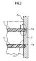
Fig. 2 is a cross-sectional view schematically showing a cross-section along a line SA1-SA1 ofFig. 1 . -
Fig. 3 is an enlarged cross-sectional view of a part B ofFig. 2 which is observed with an electron microscope. -
Fig. 4 is a cross-sectional view of a closed die schematically showing a situation where the seat structure member ofFig. 1 is put in a die for injection molding of a strength member. -
Fig. 5 is a cross-sectional view schematically showing a seat structure member including a strength member existing between a second movable die and the movable die ofFig. 4 which is opened. -
Fig. 6 is a cross-sectional view schematically showing a state where the seat structure member is detached from the second movable die ofFig. 5 . -
Fig. 7 is a perspective view showing a vehicle seat according to a second embodiment of the present invention, particularly showing a structure member of the vehicle seat. -
Fig. 8 is a cross-sectional view schematically showing a cross-section along a line SA2-SA2 ofFig. 7 . -
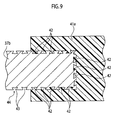
Fig. 9 is an enlarged cross-sectional view of a part B ofFig. 8 which is observed with an electron microscope. -
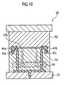
Fig. 10 is a cross-sectional view of a closed die schematically showing a situation where a plate member of the seat structure member ofFig. 7 is put in a die for injection molding of a strength member. -
Fig. 11 is a cross-sectional view schematically showing a seat structure member including a strength member existing between a second movable die and a movable die ofFig. 10 which is opened. -
Fig. 12 is a cross-sectional view showing a state where the seat structure member is detached from the second movable die ofFig. 11 . - Hereinafter, a description is given of embodiments of the present invention in detail with reference to the drawings. First, a first embodiment of the present invention is described taking an automobile as an example of vehicles with reference to
FIGS. 1 to 3 . An automobile seat structure 1 according to the first embodiment includes: aseat back 2; a seat cushion 3; and a reclining device (not shown) supporting part between theseat back 2 and seat cushion 3. Theseat back 2 includes: aseat structure member 4; a not-shown buffer provided for theseat structure member 4; and a skin covering theseat structure member 4 and the buffer. A not-shown head rest is supported on the top of the seat back 2. Reference numeral 9 indicates a seat belt retractor. - The
seat structure member 4 includes: a pipe-shapedfirst member 5 having a substantially reverse L shape in a front view (shown inFig. 1 ); asecond member 7 welded to thefirst member 5 and a later-describedthird member 6; and thethird member 6 welded to lower ends of thesecond member 7 and thefirst member 5. As shown inFig. 1 , to thesecond member 7, astrength member 11 is fixed from the upper end to the lower end thereof. Thestrength member 11 includes plural substantially honeycomb continuous structures. - The
second member 7 is made of an iron plate. As shown inFig. 2 , wedge-shaped recesses are formed in thesurface 7a of thesecond member 7 after rust and oil are removed. PPS (polyphenylene sulfide) as hard synthetic resin is poured into the wedge-shaped recesses formed in thesurface 7a and is then hardened, thus forming wedge-shaped leg portions 11a. Thestrength member 11 is firmly supported on thesurface 7a of thesecond member 7 through theleg portions 11 a. In a view of a part B ofFig. 2 with an electronic microscope, as shown inFig. 3 , nanometer-scale anchor-shaped recesses 12 are formed in theentire surface 7a of thesecond member 7. To be specific, the size of therecesses 12 is 20 to 50 nanometers (nm). Theleg portions 11 a are embedded in therecesses 12. - In the upper end of the
second member 7, aretractor bracket 8 supporting the seat belt retractor 9 on a surface to a rear side RR is integrally formed.Reference numeral 12 indicates a guide member which guides a seat belt (not shown) rewound by the seat belt retractor so that the seat belt properly supports the occupant's shoulder.Reference numerals first member 5 so as to support stays of the head rest.Reference numeral 10 indicates a side plate which is supported on the side part of thefirst member 5 to support an upper member of a not-shown reclining device. - The
strength member 11 is made of PPS (polyphenylene sulfide) as the hard synthetic resin. First, thesecond member 7 is supported within a secondmovable die 23 arranged between afixed die 21 and amovable die 22 of a forming die 20 shown inFIGS. 4 to 6 . In this state, the hard synthetic resin is injection-molded. To be specific, PPS (polyphenylene sulfide) as the hard synthetic resin is poured onto the rough surface of thesurface 7a of thesecond member 7, that is, the surface where therecesses 12 are formed, to be solidified. Each of theleg portions 11 a thus form a wedge shape schematically shown inFig. 2 . Actually, in a view with an electronic microscope, as shown inFig. 3 , the hard synthetic resin is poured into therecesses 12 to be solidified, thus forming theleg portions 11 a of thestrength member 11. Theleg portions 11a of thestrength member 11 are therefore firmly supported by thesecond member 7.Reference numeral 24 inFIGS. 4 to 6 indicates a means of injecting PPS (polyphenylene sulfide) as the hard synthetic resin. - As described above, according to the first embodiment, the following operational effects can be obtained.
- The
second member 7 of the metallicseat structure member 4 with thesurface 7a roughened is placed within a formingdie 20, and the synthetic resin is injected into the formingdie 20 for molding. Theleg portions 11a of thestrength member 11 which are made of synthetic resin are therefore fixed to the roughenedsurface 7a of thesecond member 7. Theleg portions 11 a of thestrength member 11 made of the synthetic resin can be firmly supported on the roughenedsurface 7a. Since thestrength members 11 are made of synthetic resin, therefore, theseat structure member 4 can be lightweight although the strength of thesecond member 7 of theseat structure member 4 is considerably increased. Furthermore, thesecond member 7 itself of theseat structure member 4 can be made thin. - Moreover, the
strength member 11 is made of PPS (polyphenylene sulfide) as the hard synthetic resin. This ensures integration of thestrength member 11 made of the synthetic resin with thesecond member 7 of the metallicseat structure member 4. - Furthermore, the
second member 7 of theseat structure member 4 is made of an iron material. Accordingly, the hard synthetic resin can be surely poured into therecesses 12 formed in the roughenedsurface 7a to firmly fix theleg portions 11a of thestrength member 11. - Furthermore, the
strength member 11 includes plural continuous substantially honeycomb-shaped structures and can disperse the impact and load applied to thesecond member 7 of theseat structure member 4. This ensures absorption of the impact. - Furthermore, the
plural recesses 12 having depth of nanometer scale are formed in the roughenedsurface 7a of thesecond member 7 of theseat structure member 4. Accordingly, a person who touches thesurface 7a of thesecond member 7 of theseat structure member 4 does not feel therecesses 12. Thesecond member 7 requires just a simple surface treatment, and the manufacturing cost can be low. - Furthermore, the point of load applied to the
second member 7 of theseat structure member 4 is located at the supporting portion of the seat belt retractor 9. In the supporting portion of the seat belt retractor 9, theretractor bracket 8 is placed. Accordingly, high load due to sudden braking of the automobile or the like is added to theretractor bracket 8 through the seat belt. Thesecond member 7 of theseat structure member 4 supporting theretractor bracket 8 is reinforced by thestrength member 11 made of synthetic resin and therefore can sufficiently hold the load applied to thesecond member 7. - In the description of the first embodiment, the point of load applied to the
second member 7 is at the supporting portion of the seat belt retractor 9. In this case, high load due to sudden braking of the automobile or the like will be applied to the supporting portion of the not-shown reclining device through the seat back 2. Since thesecond member 7 of theseat structure member 4 supporting the supporting portion of the reclining device is reinforced by thestrength member 11 made of synthetic resin, thesecond member 7 can adequately bear the load applied to thesecond member 7. - Moreover, in the description of the first embodiment, the
second member 7 of theseat structure member 4 is made of an iron plate. However, thesecond member 7 may be made of aluminum, magnesium, copper, stainless, titanium, or brass instead of the iron plate. The hard synthetic resin can be surely poured into therecesses 12 formed in the roughenedsurface 7a to firmly fix theleg portions 11 a of thestrength member 11. - In the description of the first embodiment, the
strength member 11 made of synthetic resin is made of PPS (polyphenylene sulfide). However, instead of PPS (polyphenylene sulfide), thestrength member 11 may be made of PBT (polybutylene terephthalate) or PA (polyamide). This ensures the integration of thestrength member 11 of synthetic resin with thesecond member 7 of the metallicseat structure member 4. - Furthermore, in the description of the first embodiment, an example of the vehicle seat structure is the automobile seat structure. However, the vehicle seat structure is not limited to the automobile seat structure and may be a vehicle seat structure for ships, aircrafts, railroad cars, or the like.
- Next, a description is give of an
automobile seat structure 31 according to a second embodiment of the present invention usingFIGS. 7 to 9 . Theautomobile seat structure 31 according to the second embodiment of the present invention includes a seat back 2, a seat cushion 3, and a reclining device (not shown) supporting a part between the seat back 2 and the seat cushion 3. The seat back 2 includes aseat structure member 4, a not-shown buffer material provided for theseat structure member 4, and a skin covering theseat structure member 4 and the buffer material. A not-shown head rest is supported on the top of the seat back 2. Reference numeral 9 indicates a seat belt retractor. - The
seat structure member 4 includes: afirst member 5 composed of an iron pipe having a substantially reverse L shape in a front view (seeFig. 7 ); asecond member 37 which is extended in the vertical direction to the right side RH of thefirst member 5 and is welded to thefirst member 5 and a later-describedthird member 6; and thethird member 6 welded to the lower ends of thesecond member 37 and thefirst member 5. - In the upper end of the
second member 37, theretractor bracket 8 supporting the seat belt retractor 9 on the rear side RR is integrally formed.Reference numeral 12 ofFig. 7 indicates a guide member which guides a seat belt (not shown) rewound by the seat belt retractor 9 so that the seat belt can properly support the occupant's shoulder. - As shown in
Fig. 8 , thesecond member 37 includes arear plate 37a, aside plate 37b, and afront plate 37c, each of which is composed of an iron plate. The rear andside plates front plate 37c is subjected to bending. The rear andside plates first strength member 41 a, and the side andfront plates strength members front plates 37a to 37b are connected through the strength members (41 a and 4b) to form a single continuous member (the second member 37). - After removal of rust and oil sticking to the surface of the
side plate 37b, as shown inFig. 9 , nanometer-scale anchor-shapedrecesses 43 are formed in theentire surface 44 of theside plate 37b. To be specific, each anchor-shapedrecess 43 has a size of 20 to 50 nanometers (nm). Forming therecesses 43 provides the surface (rough surface) 44 roughened to depth of nanometer scale. PPS (polyphenylene sulfide) is poured into therecesses 43 formed in thesurface 44 of theside plate 37 to be solidified, thus forming wedge-shapedleg portions 42. Thefirst strength member 41 a is firmly fixed to thesurface 44 of theside plate 37b by theleg portions 42.Fig. 9 shows the connection between theside plate 37b and thefirst strength member 41 a. However, the connections of the rear, side, andfront plates - The rear, side, and
front plates movable die 53 provided between a fixeddie 51 and amovable die 52 of a formingdie 50 shown inFIGS. 10 to 12 . In this state, hard synthetic resin is injected into between the rear andside plates front plates recesses 43 formed in thesurfaces 44 of the rear, side, andfront plates Fig. 9 , the hard synthetic resin is poured into therecesses 43 and then hardened to form theleg portions 42 of the strength members (41 a and 41 b). Theleg portions 42 of the strength members (41 a and 41 b) therefore strongly support the rear, side, andfront plates front plates Reference numeral 54 inFIGS. 10 to 12 indicates a means for injecting PPS (polyphenylene sulfide) as the hard synthetic resin. - As described above, according to a second embodiment, the following operational effects can be obtained.
- The metallic rear, side, and
front plates surfaces 44 roughened to depth of nanometer scale and are plate-shaped or bent, are placed within the formingdie 50, and the hard synthetic resin is then injected for molding. At this time, theleg portions 42 of the strength members (41 a and 41 b) made of the hard synthetic resin are firmly fixed to thesurfaces 44 roughened to the nanometer-scale depth. The strength members (41 a, 41 b) can therefore firmly support the rear, side, andfront plates second member 37 has therefore strength considerably increased although the rear, side, andfront plates seat structure member 4 may be formed without deep drawing independently of choice of the metallic material of the frame and the like. - Moreover, the nanometer-
scale recesses 43 are formed in the roughened surfaces 44 of thesecond member 37, and a person who touches the surface of thesecond member 37 do not feel the recesses. Accordingly, it is necessary to perform just an easy surface treatment, thus reducing the manufacturing cost. - Furthermore, the strength members (41 a, 41 b) are made of PPS (polyphenylene sulfide) as the hard synthetic resin. This can ensure integration of the strength members (41 a, 41 b) made of synthetic resin with the metallic
second member 37. - Furthermore, the
second member 37 of the seat structure member is made of an iron material. Accordingly, the hard synthetic resin is surely poured into therecesses 43 formed in the roughenedsurface 44 to firmly fix theleg portions 42 of the strength members (41 a, 41 b). - Still furthermore, the rear, side, and
front plates second member 37, thus ensuring absorption of the impact. - In the description of the second embodiment, the material of the
second member 37 of theseat structure member 4 is an iron plate. However, the material of thesecond member 37 may be aluminum, magnesium, copper, stainless, titanium, or brass instead of the iron plate. The hard synthetic resin can be surely poured into therecesses 12 formed in the roughenedsurface 7a to firmly fix theleg portions 11 a of thestrength members 11. - Moreover, in the description of the first embodiment, the strength members (41a, 41 b) made of synthetic resin is made of PPS (polyphenylene sulfide). However, instead of PPS (polyphenylene sulfide), the
strength member 11 may be made of PBT (polybutylene terephthalate) or PA (polyamide). This ensures integration of the strength members (41 a, 41 b) of the synthetic resin with thesecond member 37 of the metallicseat structure member 4. - Furthermore, the description of the second embodiment is given with the automobile seat structure as an example of the vehicle seat structure. However, the vehicle seat structure is not limited to the automobile seat structure and may be a vehicle seat structure for ships, aircrafts, railroad cars, or the like.
- This invention is based upon and claims the benefit of priority to Japanese Patent Applications No.
P2009-211815, filed on September 14, 2009 P2009-211801, filed on September 14, 2009 - In the vehicle seat structure according to the first embodiment of the present invention, the
second member 7 of the metallicseat structure member 4 with the surface roughened is placed within the formingdie 20, and synthetic resin is injected into the formingdie 20 for molding. Theleg portions 11 a of thestrength member 11 made of synthetic resin are therefore firmly fixed to the roughenedsurface 7a of thesecond member 7. According to the vehicle seat structure, theleg portions 11 a of thestrength members 11 made of synthetic resin can be fixed to the roughenedsurface 7a of thesecond member 7. It is therefore possible to provide a vehicle seat structure including a lightweight means capable of sufficiently withstanding the impact load applied to the metallic seat structure member such as a seat back frame. - Moreover, in the second embodiment of the present invention, the members (37a, 37b, and 37c) of the metallic
second member 37 which is plate shaped or bent and has thesurfaces 44 roughened to depth of nanometer scale are arranged in a squared U shape within the formingdie 50, and hard synthetic resin is then injected into for molding. Theleg portions 42 of the strength members (41 a and 41b) are therefore firmly fixed to thesurface 44 of each member (37a to 37c). Accordingly, it is possible to provide a vehicle seat structure including the strongsecond member 37 without deep drawing independently of choice of the metallic material of the frame and the like. - Consequently, the vehicle seat structures according to the first and second embodiments of the present invention are industrially applicable.
Claims (9)
- A vehicle seat structure, comprising:a metallic seat structure member with a surface roughened; and a strength member made of synthetic resin, whereinthe seat structure member is placed within a forming die, into which synthetic resin is injected for molding to fix a leg portion of the strength member made of the synthetic resin to the roughened surface of the seat structure member.
- A vehicle seat structure, comprising:metallic seat structure members each of which has a surface roughened to depth of nanometer scale and is plate-shaped or bent; and a strength member made of hard synthetic resin, whereinthe metallic seat structure members are placed within a forming die, into which the synthetic resin is injected for molding to fix a leg portion of the strength member made of the synthetic resin to the roughened surface of each seat structure member.
- The vehicle seat structure according to claims 1 or 2, wherein
the strength member is made of any one of
PPS (polyphenylene sulfide), PBT (polybutylene
terephthalate), and PA (polyamide). - The vehicle seat structure according to any one of claims 1 to 3, wherein
the seat structure member is made of any one of aluminum, magnesium, copper, stainless, titanium, iron, and brass. - The vehicle seat structure according to any one of claims 1, 3, and 4, wherein
the strength member includes a plurality of continuous substantially-honeycomb structures. - The vehicle seat structure according to any one of claims 1 to 5, wherein in the roughened surface of the seat structure member, a plurality of recesses having depth of nanometer scale are formed.
- The vehicle seat structure according to any one of claims 1 and 3 to 6, wherein
the point of load added to the seat structure member is located at a supporting portion of a seat belt retractor. - The vehicle seat structure according to any one of claims 1 and 3 to 6, wherein
the point of load applied to the seat structure member is located at a supporting portion of a reclining apparatus. - The vehicle seat structure according to any one of claims 2 to 4, wherein
the seat structure members are connected by the strength member.
Applications Claiming Priority (3)
| Application Number | Priority Date | Filing Date | Title |
|---|---|---|---|
| JP2009211815A JP5960941B2 (en) | 2009-09-14 | 2009-09-14 | Vehicle seat structure |
| JP2009211801A JP2011057164A (en) | 2009-09-14 | 2009-09-14 | Seat structure for vehicle |
| PCT/JP2010/065258 WO2011030736A1 (en) | 2009-09-14 | 2010-09-06 | Vehicle seat structure |
Publications (3)
| Publication Number | Publication Date |
|---|---|
| EP2479060A1 true EP2479060A1 (en) | 2012-07-25 |
| EP2479060A4 EP2479060A4 (en) | 2014-07-30 |
| EP2479060B1 EP2479060B1 (en) | 2017-08-23 |
Family
ID=43732408
Family Applications (1)
| Application Number | Title | Priority Date | Filing Date |
|---|---|---|---|
| EP10815333.9A Not-in-force EP2479060B1 (en) | 2009-09-14 | 2010-09-06 | Vehicle seat structure |
Country Status (4)
| Country | Link |
|---|---|
| US (1) | US9090190B2 (en) |
| EP (1) | EP2479060B1 (en) |
| CN (1) | CN102639357B (en) |
| WO (1) | WO2011030736A1 (en) |
Cited By (2)
| Publication number | Priority date | Publication date | Assignee | Title |
|---|---|---|---|---|
| DE102017215092A1 (en) | 2017-08-29 | 2019-02-28 | Elringklinger Ag | Molded component, seat and method for producing a molded component |
| WO2019149771A1 (en) * | 2018-01-30 | 2019-08-08 | Recaro Aircraft Seating Gmbh & Co. Kg | Aircraft seat device |
Families Citing this family (15)
| Publication number | Priority date | Publication date | Assignee | Title |
|---|---|---|---|---|
| US20150352982A1 (en) * | 2012-12-28 | 2015-12-10 | Ts Tech Co., Ltd. | Seat device |
| CN103317727B (en) * | 2013-06-09 | 2015-12-09 | 江苏景越塑料科技有限公司 | A kind of processing method of double-colored boxed cassette |
| WO2014205329A1 (en) * | 2013-06-20 | 2014-12-24 | Zodiac Seats Us Llc | Pivotable attachment device attachable onto tracks |
| JP2016533298A (en) * | 2013-10-18 | 2016-10-27 | ジョンソン コントロールズ テクノロジー カンパニーJohnson Controls Technology Company | Reinforcement for vehicle seat structures and components |
| JP6181563B2 (en) * | 2014-01-22 | 2017-08-16 | テイ・エス テック株式会社 | Vehicle seat |
| DE102014006886A1 (en) * | 2014-05-09 | 2015-11-12 | GM Global Technology Operations LLC (n. d. Gesetzen des Staates Delaware) | A method of manufacturing a seat back structure of a vehicle seat |
| WO2015183730A1 (en) * | 2014-05-27 | 2015-12-03 | Johnson Controls Technology Company | Seat back and process of making seat back of hybrid construction |
| JP6400999B2 (en) * | 2014-09-26 | 2018-10-03 | 株式会社タチエス | Vehicle seat |
| DE102016011304A1 (en) | 2016-09-19 | 2018-03-22 | Lanxess Deutschland Gmbh | Seat structure element for a motor vehicle seat, method for its production and motor vehicle seat with such a seat structure element |
| EP3565735A4 (en) * | 2017-01-05 | 2020-01-08 | Adient Engineering and IP GmbH | Rear seat backrest with lightweight aluminum back panel |
| JP6939091B2 (en) * | 2017-05-26 | 2021-09-22 | トヨタ紡織株式会社 | Vehicle seat |
| KR102153725B1 (en) * | 2018-12-12 | 2020-09-09 | 주식회사 디에스시동탄 | Seat frame assembly and method for manufacturing the same |
| FR3099729B1 (en) * | 2019-08-05 | 2021-12-10 | Faurecia Systemes Dechappement | Composite structure with reinforced articulation |
| EP4021805B1 (en) * | 2019-08-29 | 2025-12-17 | Safran Seats USA LLC | Auxetic energy absorbing passenger safety assemblies |
| JP7700709B2 (en) * | 2022-03-11 | 2025-07-01 | トヨタ紡織株式会社 | Vehicle seat frame |
Family Cites Families (23)
| Publication number | Priority date | Publication date | Assignee | Title |
|---|---|---|---|---|
| US1747964A (en) * | 1926-02-02 | 1930-02-18 | Wirth Johann Karl | Process of uniting parts of artificial resin and article made thereby |
| US3451719A (en) * | 1967-11-24 | 1969-06-24 | Gen Motors Corp | Seat anchorage |
| JPS6011609B2 (en) | 1978-06-08 | 1985-03-27 | 日本発条株式会社 | plastic sheet frame |
| JPS61190251U (en) * | 1985-05-20 | 1986-11-27 | ||
| JPS6275916U (en) * | 1985-10-30 | 1987-05-15 | ||
| DE3841532A1 (en) | 1988-12-09 | 1990-06-13 | Bayer Ag | BACKREST SUPPORT STRUCTURE FOR A VEHICLE SEAT AND VEHICLE SEAT BACKREST WITH THIS BACKREST SUPPORT STRUCTURE |
| JP2000271957A (en) | 1999-03-26 | 2000-10-03 | Polyplastics Co | Manufacturing method of metal insert resin molded product |
| JP3714039B2 (en) * | 1999-06-18 | 2005-11-09 | 日産自動車株式会社 | Seat belt integrated seat |
| JP3467471B2 (en) | 1999-12-08 | 2003-11-17 | ポリプラスチックス株式会社 | Manufacturing method of metal insert resin composite molding |
| WO2001043940A1 (en) | 1999-12-17 | 2001-06-21 | Cooper Tire & Rubber Company | Tube product with molded on bracket |
| DE10008204C2 (en) * | 2000-02-23 | 2002-06-27 | Faurecia Autositze Gmbh & Co | Component connection between two components of a motor vehicle seat |
| US20050168041A1 (en) * | 2000-10-04 | 2005-08-04 | Glance Patrick M. | Thin, double-wall molded seat frame system |
| CN1239320C (en) | 2001-12-28 | 2006-02-01 | 大成普拉斯株式会社 | Composite comprising aluminium alloy and resin and method for manufacturing the same |
| JP2004216425A (en) | 2003-01-15 | 2004-08-05 | Taisei Plas Co Ltd | Connection joint of aluminum alloy pipe and method of manufacturing the same |
| JP2004229688A (en) * | 2003-01-28 | 2004-08-19 | Asahi Tec Corp | Seat back frame and method of manufacturing the same |
| JP2007008272A (en) * | 2005-06-29 | 2007-01-18 | Asahi Tec Corp | Seat frame |
| JP4927491B2 (en) | 2005-10-04 | 2012-05-09 | 大成プラス株式会社 | Metal-resin composite and method for producing the same |
| EP2057034A1 (en) * | 2006-08-14 | 2009-05-13 | Basf Se | Composite component |
| US20080070001A1 (en) | 2006-09-19 | 2008-03-20 | Harri Lasarov | Plastic-acceptor hybrid components |
| KR101188027B1 (en) | 2006-10-16 | 2012-10-04 | 다이세이 플라스 가부시끼가이샤 | Composite of metal with resin and process for producing the same |
| JP2008184144A (en) | 2007-01-31 | 2008-08-14 | Toyota Motor Corp | Vehicle seat |
| DE102007050091A1 (en) * | 2007-10-19 | 2009-04-23 | GM Global Technology Operations, Inc., Detroit | Vehicle seat with a rotating back section |
| FR2965520A1 (en) * | 2010-10-04 | 2012-04-06 | Peugeot Citroen Automobiles Sa | Seat for motor vehicle, has base with armature that comprises two rigid polymer parts, where one of parts serves as contact interface arranged in contact with vehicle and other part serves as lining interface defining base height in vehicle |
-
2010
- 2010-09-06 EP EP10815333.9A patent/EP2479060B1/en not_active Not-in-force
- 2010-09-06 WO PCT/JP2010/065258 patent/WO2011030736A1/en not_active Ceased
- 2010-09-06 CN CN201080040940.3A patent/CN102639357B/en not_active Expired - Fee Related
- 2010-09-06 US US13/395,872 patent/US9090190B2/en active Active
Cited By (3)
| Publication number | Priority date | Publication date | Assignee | Title |
|---|---|---|---|---|
| DE102017215092A1 (en) | 2017-08-29 | 2019-02-28 | Elringklinger Ag | Molded component, seat and method for producing a molded component |
| WO2019042588A1 (en) | 2017-08-29 | 2019-03-07 | Elringklinger Ag | Molded part, seat and method for producing a molded part |
| WO2019149771A1 (en) * | 2018-01-30 | 2019-08-08 | Recaro Aircraft Seating Gmbh & Co. Kg | Aircraft seat device |
Also Published As
| Publication number | Publication date |
|---|---|
| EP2479060A4 (en) | 2014-07-30 |
| EP2479060B1 (en) | 2017-08-23 |
| CN102639357A (en) | 2012-08-15 |
| CN102639357B (en) | 2016-01-20 |
| US20120223565A1 (en) | 2012-09-06 |
| US9090190B2 (en) | 2015-07-28 |
| WO2011030736A1 (en) | 2011-03-17 |
Similar Documents
| Publication | Publication Date | Title |
|---|---|---|
| US9090190B2 (en) | Vehicle seat structure | |
| CN203267825U (en) | vehicle seat frame | |
| JP5690093B2 (en) | Vehicle seat structure | |
| CN104602953B (en) | Seat for vehicle | |
| CN102574483B (en) | Backrest, in particular for a rear seat arrangement of a motor vehicle | |
| CN102666198B (en) | Vehicle seating system, seat bottom chassis, and method of manufacturing the seat bottom chassis | |
| US20090134686A1 (en) | Vehicle seat | |
| JP2009154691A (en) | Vehicle seat | |
| EP2894062B1 (en) | Vehicle seat, and seat frame for vehicle seat | |
| CN115848248B (en) | Car seat back frame | |
| CN110979118A (en) | Vehicle seat | |
| JP2019059285A (en) | Vehicle seat | |
| JP5960941B2 (en) | Vehicle seat structure | |
| US11110822B2 (en) | Sliding device | |
| JP4006806B2 (en) | Seat back frame that absorbs impact energy from cargo | |
| CN104837686A (en) | Seatbelt winder support with programmed deformation | |
| JP2008189273A (en) | Front underrun protector | |
| US7469970B2 (en) | Reinforcing structure for three-point type seat belt | |
| JP2000016241A (en) | Central seat belt attachment device for vehicle seats | |
| JP2013126833A (en) | Airbag device and module cover thereof | |
| JP6016056B2 (en) | Vehicle seat rail mounting structure | |
| ATE534548T1 (en) | SEAT ARRANGEMENT FOR A MOTOR VEHICLE HAVING A SYSTEM FOR PREVENTING SUBMERGING, IN PARTICULAR IN THE SHAPE OF A TORSON'S BILL | |
| JP4222864B2 (en) | Underrun protector and manufacturing method thereof | |
| US10647228B2 (en) | Protective seat load floor for hybrid vehicles | |
| JP2011057164A (en) | Seat structure for vehicle |
Legal Events
| Date | Code | Title | Description |
|---|---|---|---|
| PUAI | Public reference made under article 153(3) epc to a published international application that has entered the european phase |
Free format text: ORIGINAL CODE: 0009012 |
|
| 17P | Request for examination filed |
Effective date: 20120323 |
|
| AK | Designated contracting states |
Kind code of ref document: A1 Designated state(s): AL AT BE BG CH CY CZ DE DK EE ES FI FR GB GR HR HU IE IS IT LI LT LU LV MC MK MT NL NO PL PT RO SE SI SK SM TR |
|
| DAX | Request for extension of the european patent (deleted) | ||
| A4 | Supplementary search report drawn up and despatched |
Effective date: 20140627 |
|
| RIC1 | Information provided on ipc code assigned before grant |
Ipc: B29L 31/30 20060101ALN20140623BHEP Ipc: B29C 45/14 20060101ALI20140623BHEP Ipc: B60N 2/68 20060101AFI20140623BHEP |
|
| 17Q | First examination report despatched |
Effective date: 20160525 |
|
| REG | Reference to a national code |
Ref country code: DE Ref legal event code: R079 Ref document number: 602010044702 Country of ref document: DE Free format text: PREVIOUS MAIN CLASS: B60N0002440000 Ipc: B60N0002680000 |
|
| GRAP | Despatch of communication of intention to grant a patent |
Free format text: ORIGINAL CODE: EPIDOSNIGR1 |
|
| RIC1 | Information provided on ipc code assigned before grant |
Ipc: B29L 31/30 20060101ALN20170406BHEP Ipc: B29C 45/14 20060101ALI20170406BHEP Ipc: B60N 2/68 20060101AFI20170406BHEP |
|
| INTG | Intention to grant announced |
Effective date: 20170502 |
|
| GRAS | Grant fee paid |
Free format text: ORIGINAL CODE: EPIDOSNIGR3 |
|
| GRAA | (expected) grant |
Free format text: ORIGINAL CODE: 0009210 |
|
| AK | Designated contracting states |
Kind code of ref document: B1 Designated state(s): AL AT BE BG CH CY CZ DE DK EE ES FI FR GB GR HR HU IE IS IT LI LT LU LV MC MK MT NL NO PL PT RO SE SI SK SM TR |
|
| RAP1 | Party data changed (applicant data changed or rights of an application transferred) |
Owner name: JOHNSON CONTROLS TECHNOLOGY COMPANY |
|
| REG | Reference to a national code |
Ref country code: GB Ref legal event code: FG4D |
|
| REG | Reference to a national code |
Ref country code: CH Ref legal event code: EP |
|
| REG | Reference to a national code |
Ref country code: AT Ref legal event code: REF Ref document number: 920940 Country of ref document: AT Kind code of ref document: T Effective date: 20170915 |
|
| REG | Reference to a national code |
Ref country code: IE Ref legal event code: FG4D |
|
| REG | Reference to a national code |
Ref country code: DE Ref legal event code: R096 Ref document number: 602010044702 Country of ref document: DE |
|
| REG | Reference to a national code |
Ref country code: FR Ref legal event code: PLFP Year of fee payment: 8 |
|
| RAP2 | Party data changed (patent owner data changed or rights of a patent transferred) |
Owner name: ADIENT LUXEMBOURG HOLDING S.A R.L. |
|
| REG | Reference to a national code |
Ref country code: NL Ref legal event code: MP Effective date: 20170823 |
|
| REG | Reference to a national code |
Ref country code: LT Ref legal event code: MG4D |
|
| REG | Reference to a national code |
Ref country code: AT Ref legal event code: MK05 Ref document number: 920940 Country of ref document: AT Kind code of ref document: T Effective date: 20170823 |
|
| PG25 | Lapsed in a contracting state [announced via postgrant information from national office to epo] |
Ref country code: NL Free format text: LAPSE BECAUSE OF FAILURE TO SUBMIT A TRANSLATION OF THE DESCRIPTION OR TO PAY THE FEE WITHIN THE PRESCRIBED TIME-LIMIT Effective date: 20170823 Ref country code: FI Free format text: LAPSE BECAUSE OF FAILURE TO SUBMIT A TRANSLATION OF THE DESCRIPTION OR TO PAY THE FEE WITHIN THE PRESCRIBED TIME-LIMIT Effective date: 20170823 Ref country code: LT Free format text: LAPSE BECAUSE OF FAILURE TO SUBMIT A TRANSLATION OF THE DESCRIPTION OR TO PAY THE FEE WITHIN THE PRESCRIBED TIME-LIMIT Effective date: 20170823 Ref country code: NO Free format text: LAPSE BECAUSE OF FAILURE TO SUBMIT A TRANSLATION OF THE DESCRIPTION OR TO PAY THE FEE WITHIN THE PRESCRIBED TIME-LIMIT Effective date: 20171123 Ref country code: HR Free format text: LAPSE BECAUSE OF FAILURE TO SUBMIT A TRANSLATION OF THE DESCRIPTION OR TO PAY THE FEE WITHIN THE PRESCRIBED TIME-LIMIT Effective date: 20170823 Ref country code: SE Free format text: LAPSE BECAUSE OF FAILURE TO SUBMIT A TRANSLATION OF THE DESCRIPTION OR TO PAY THE FEE WITHIN THE PRESCRIBED TIME-LIMIT Effective date: 20170823 Ref country code: AT Free format text: LAPSE BECAUSE OF FAILURE TO SUBMIT A TRANSLATION OF THE DESCRIPTION OR TO PAY THE FEE WITHIN THE PRESCRIBED TIME-LIMIT Effective date: 20170823 |
|
| PG25 | Lapsed in a contracting state [announced via postgrant information from national office to epo] |
Ref country code: GR Free format text: LAPSE BECAUSE OF FAILURE TO SUBMIT A TRANSLATION OF THE DESCRIPTION OR TO PAY THE FEE WITHIN THE PRESCRIBED TIME-LIMIT Effective date: 20171124 Ref country code: BG Free format text: LAPSE BECAUSE OF FAILURE TO SUBMIT A TRANSLATION OF THE DESCRIPTION OR TO PAY THE FEE WITHIN THE PRESCRIBED TIME-LIMIT Effective date: 20171123 Ref country code: IS Free format text: LAPSE BECAUSE OF FAILURE TO SUBMIT A TRANSLATION OF THE DESCRIPTION OR TO PAY THE FEE WITHIN THE PRESCRIBED TIME-LIMIT Effective date: 20171223 Ref country code: ES Free format text: LAPSE BECAUSE OF FAILURE TO SUBMIT A TRANSLATION OF THE DESCRIPTION OR TO PAY THE FEE WITHIN THE PRESCRIBED TIME-LIMIT Effective date: 20170823 Ref country code: PL Free format text: LAPSE BECAUSE OF FAILURE TO SUBMIT A TRANSLATION OF THE DESCRIPTION OR TO PAY THE FEE WITHIN THE PRESCRIBED TIME-LIMIT Effective date: 20170823 Ref country code: LV Free format text: LAPSE BECAUSE OF FAILURE TO SUBMIT A TRANSLATION OF THE DESCRIPTION OR TO PAY THE FEE WITHIN THE PRESCRIBED TIME-LIMIT Effective date: 20170823 |
|
| RAP2 | Party data changed (patent owner data changed or rights of a patent transferred) |
Owner name: ADIENT LUXEMBOURG HOLDING S.A R.L. |
|
| PG25 | Lapsed in a contracting state [announced via postgrant information from national office to epo] |
Ref country code: RO Free format text: LAPSE BECAUSE OF FAILURE TO SUBMIT A TRANSLATION OF THE DESCRIPTION OR TO PAY THE FEE WITHIN THE PRESCRIBED TIME-LIMIT Effective date: 20170823 Ref country code: DK Free format text: LAPSE BECAUSE OF FAILURE TO SUBMIT A TRANSLATION OF THE DESCRIPTION OR TO PAY THE FEE WITHIN THE PRESCRIBED TIME-LIMIT Effective date: 20170823 Ref country code: CZ Free format text: LAPSE BECAUSE OF FAILURE TO SUBMIT A TRANSLATION OF THE DESCRIPTION OR TO PAY THE FEE WITHIN THE PRESCRIBED TIME-LIMIT Effective date: 20170823 |
|
| REG | Reference to a national code |
Ref country code: CH Ref legal event code: PL |
|
| REG | Reference to a national code |
Ref country code: DE Ref legal event code: R097 Ref document number: 602010044702 Country of ref document: DE |
|
| PG25 | Lapsed in a contracting state [announced via postgrant information from national office to epo] |
Ref country code: SK Free format text: LAPSE BECAUSE OF FAILURE TO SUBMIT A TRANSLATION OF THE DESCRIPTION OR TO PAY THE FEE WITHIN THE PRESCRIBED TIME-LIMIT Effective date: 20170823 Ref country code: IT Free format text: LAPSE BECAUSE OF FAILURE TO SUBMIT A TRANSLATION OF THE DESCRIPTION OR TO PAY THE FEE WITHIN THE PRESCRIBED TIME-LIMIT Effective date: 20170823 Ref country code: EE Free format text: LAPSE BECAUSE OF FAILURE TO SUBMIT A TRANSLATION OF THE DESCRIPTION OR TO PAY THE FEE WITHIN THE PRESCRIBED TIME-LIMIT Effective date: 20170823 Ref country code: SM Free format text: LAPSE BECAUSE OF FAILURE TO SUBMIT A TRANSLATION OF THE DESCRIPTION OR TO PAY THE FEE WITHIN THE PRESCRIBED TIME-LIMIT Effective date: 20170823 Ref country code: MC Free format text: LAPSE BECAUSE OF FAILURE TO SUBMIT A TRANSLATION OF THE DESCRIPTION OR TO PAY THE FEE WITHIN THE PRESCRIBED TIME-LIMIT Effective date: 20170823 |
|
| REG | Reference to a national code |
Ref country code: IE Ref legal event code: MM4A |
|
| REG | Reference to a national code |
Ref country code: BE Ref legal event code: MM Effective date: 20170930 |
|
| PG25 | Lapsed in a contracting state [announced via postgrant information from national office to epo] |
Ref country code: LU Free format text: LAPSE BECAUSE OF NON-PAYMENT OF DUE FEES Effective date: 20170906 |
|
| PLBE | No opposition filed within time limit |
Free format text: ORIGINAL CODE: 0009261 |
|
| STAA | Information on the status of an ep patent application or granted ep patent |
Free format text: STATUS: NO OPPOSITION FILED WITHIN TIME LIMIT |
|
| GBPC | Gb: european patent ceased through non-payment of renewal fee |
Effective date: 20171123 |
|
| PG25 | Lapsed in a contracting state [announced via postgrant information from national office to epo] |
Ref country code: IE Free format text: LAPSE BECAUSE OF NON-PAYMENT OF DUE FEES Effective date: 20170906 Ref country code: CH Free format text: LAPSE BECAUSE OF NON-PAYMENT OF DUE FEES Effective date: 20170930 Ref country code: LI Free format text: LAPSE BECAUSE OF NON-PAYMENT OF DUE FEES Effective date: 20170930 |
|
| 26N | No opposition filed |
Effective date: 20180524 |
|
| PG25 | Lapsed in a contracting state [announced via postgrant information from national office to epo] |
Ref country code: SI Free format text: LAPSE BECAUSE OF FAILURE TO SUBMIT A TRANSLATION OF THE DESCRIPTION OR TO PAY THE FEE WITHIN THE PRESCRIBED TIME-LIMIT Effective date: 20170823 Ref country code: BE Free format text: LAPSE BECAUSE OF NON-PAYMENT OF DUE FEES Effective date: 20170930 |
|
| PG25 | Lapsed in a contracting state [announced via postgrant information from national office to epo] |
Ref country code: MT Free format text: LAPSE BECAUSE OF NON-PAYMENT OF DUE FEES Effective date: 20170906 |
|
| PG25 | Lapsed in a contracting state [announced via postgrant information from national office to epo] |
Ref country code: GB Free format text: LAPSE BECAUSE OF NON-PAYMENT OF DUE FEES Effective date: 20171123 |
|
| PG25 | Lapsed in a contracting state [announced via postgrant information from national office to epo] |
Ref country code: HU Free format text: LAPSE BECAUSE OF FAILURE TO SUBMIT A TRANSLATION OF THE DESCRIPTION OR TO PAY THE FEE WITHIN THE PRESCRIBED TIME-LIMIT; INVALID AB INITIO Effective date: 20100906 |
|
| PG25 | Lapsed in a contracting state [announced via postgrant information from national office to epo] |
Ref country code: CY Free format text: LAPSE BECAUSE OF NON-PAYMENT OF DUE FEES Effective date: 20170823 |
|
| PG25 | Lapsed in a contracting state [announced via postgrant information from national office to epo] |
Ref country code: MK Free format text: LAPSE BECAUSE OF FAILURE TO SUBMIT A TRANSLATION OF THE DESCRIPTION OR TO PAY THE FEE WITHIN THE PRESCRIBED TIME-LIMIT Effective date: 20170823 |
|
| REG | Reference to a national code |
Ref country code: DE Ref legal event code: R081 Ref document number: 602010044702 Country of ref document: DE Owner name: ADIENT US LLC, PLYMOUTH, US Free format text: FORMER OWNER: JOHNSON CONTROLS TECHNOLOGY CO., MILWAUKEE, WIS., US Ref country code: DE Ref legal event code: R081 Ref document number: 602010044702 Country of ref document: DE Owner name: ADIENT LUXEMBOURG HOLDING S.A R.L., LU Free format text: FORMER OWNER: JOHNSON CONTROLS TECHNOLOGY CO., MILWAUKEE, WIS., US |
|
| PG25 | Lapsed in a contracting state [announced via postgrant information from national office to epo] |
Ref country code: TR Free format text: LAPSE BECAUSE OF FAILURE TO SUBMIT A TRANSLATION OF THE DESCRIPTION OR TO PAY THE FEE WITHIN THE PRESCRIBED TIME-LIMIT Effective date: 20170823 |
|
| PG25 | Lapsed in a contracting state [announced via postgrant information from national office to epo] |
Ref country code: PT Free format text: LAPSE BECAUSE OF FAILURE TO SUBMIT A TRANSLATION OF THE DESCRIPTION OR TO PAY THE FEE WITHIN THE PRESCRIBED TIME-LIMIT Effective date: 20170823 |
|
| PG25 | Lapsed in a contracting state [announced via postgrant information from national office to epo] |
Ref country code: AL Free format text: LAPSE BECAUSE OF FAILURE TO SUBMIT A TRANSLATION OF THE DESCRIPTION OR TO PAY THE FEE WITHIN THE PRESCRIBED TIME-LIMIT Effective date: 20170823 |
|
| REG | Reference to a national code |
Ref country code: DE Ref legal event code: R082 Ref document number: 602010044702 Country of ref document: DE Representative=s name: LIEDHEGENER, RALF, DIPL.-ING., DE |
|
| REG | Reference to a national code |
Ref country code: DE Ref legal event code: R081 Ref document number: 602010044702 Country of ref document: DE Owner name: ADIENT US LLC, PLYMOUTH, US Free format text: FORMER OWNER: ADIENT LUXEMBOURG HOLDING S.A R.L., LUXEMBOURG, LU |
|
| PGFP | Annual fee paid to national office [announced via postgrant information from national office to epo] |
Ref country code: DE Payment date: 20220928 Year of fee payment: 13 |
|
| PGFP | Annual fee paid to national office [announced via postgrant information from national office to epo] |
Ref country code: FR Payment date: 20220926 Year of fee payment: 13 |
|
| REG | Reference to a national code |
Ref country code: DE Ref legal event code: R119 Ref document number: 602010044702 Country of ref document: DE |
|
| PG25 | Lapsed in a contracting state [announced via postgrant information from national office to epo] |
Ref country code: FR Free format text: LAPSE BECAUSE OF NON-PAYMENT OF DUE FEES Effective date: 20230930 Ref country code: DE Free format text: LAPSE BECAUSE OF NON-PAYMENT OF DUE FEES Effective date: 20240403 |