EP2478977A1 - Curved closed-section structural component and method for manufacturing same - Google Patents
Curved closed-section structural component and method for manufacturing same Download PDFInfo
- Publication number
- EP2478977A1 EP2478977A1 EP10817315A EP10817315A EP2478977A1 EP 2478977 A1 EP2478977 A1 EP 2478977A1 EP 10817315 A EP10817315 A EP 10817315A EP 10817315 A EP10817315 A EP 10817315A EP 2478977 A1 EP2478977 A1 EP 2478977A1
- Authority
- EP
- European Patent Office
- Prior art keywords
- closed structure
- forming
- flange
- metal plates
- longitudinal direction
- Prior art date
- Legal status (The legal status is an assumption and is not a legal conclusion. Google has not performed a legal analysis and makes no representation as to the accuracy of the status listed.)
- Granted
Links
Images




Classifications
-
- B—PERFORMING OPERATIONS; TRANSPORTING
- B21—MECHANICAL METAL-WORKING WITHOUT ESSENTIALLY REMOVING MATERIAL; PUNCHING METAL
- B21D—WORKING OR PROCESSING OF SHEET METAL OR METAL TUBES, RODS OR PROFILES WITHOUT ESSENTIALLY REMOVING MATERIAL; PUNCHING METAL
- B21D47/00—Making rigid structural elements or units, e.g. honeycomb structures
- B21D47/01—Making rigid structural elements or units, e.g. honeycomb structures beams or pillars
-
- B—PERFORMING OPERATIONS; TRANSPORTING
- B21—MECHANICAL METAL-WORKING WITHOUT ESSENTIALLY REMOVING MATERIAL; PUNCHING METAL
- B21C—MANUFACTURE OF METAL SHEETS, WIRE, RODS, TUBES, PROFILES OR LIKE SEMI-MANUFACTURED PRODUCTS OTHERWISE THAN BY ROLLING; AUXILIARY OPERATIONS USED IN CONNECTION WITH METAL-WORKING WITHOUT ESSENTIALLY REMOVING MATERIAL
- B21C37/00—Manufacture of metal sheets, rods, wire, tubes, profiles or like semi-manufactured products, not otherwise provided for; Manufacture of tubes of special shape
- B21C37/06—Manufacture of metal sheets, rods, wire, tubes, profiles or like semi-manufactured products, not otherwise provided for; Manufacture of tubes of special shape of tubes or metal hoses; Combined procedures for making tubes, e.g. for making multi-wall tubes
- B21C37/08—Making tubes with welded or soldered seams
- B21C37/0803—Making tubes with welded or soldered seams the tubes having a special shape, e.g. polygonal tubes
-
- B—PERFORMING OPERATIONS; TRANSPORTING
- B21—MECHANICAL METAL-WORKING WITHOUT ESSENTIALLY REMOVING MATERIAL; PUNCHING METAL
- B21D—WORKING OR PROCESSING OF SHEET METAL OR METAL TUBES, RODS OR PROFILES WITHOUT ESSENTIALLY REMOVING MATERIAL; PUNCHING METAL
- B21D11/00—Bending not restricted to forms of material mentioned in only one of groups B21D5/00, B21D7/00, B21D9/00; Bending not provided for in groups B21D5/00 - B21D9/00; Twisting
- B21D11/20—Bending sheet metal, not otherwise provided for
-
- B—PERFORMING OPERATIONS; TRANSPORTING
- B21—MECHANICAL METAL-WORKING WITHOUT ESSENTIALLY REMOVING MATERIAL; PUNCHING METAL
- B21D—WORKING OR PROCESSING OF SHEET METAL OR METAL TUBES, RODS OR PROFILES WITHOUT ESSENTIALLY REMOVING MATERIAL; PUNCHING METAL
- B21D47/00—Making rigid structural elements or units, e.g. honeycomb structures
- B21D47/04—Making rigid structural elements or units, e.g. honeycomb structures composite sheet metal profiles
-
- B—PERFORMING OPERATIONS; TRANSPORTING
- B21—MECHANICAL METAL-WORKING WITHOUT ESSENTIALLY REMOVING MATERIAL; PUNCHING METAL
- B21D—WORKING OR PROCESSING OF SHEET METAL OR METAL TUBES, RODS OR PROFILES WITHOUT ESSENTIALLY REMOVING MATERIAL; PUNCHING METAL
- B21D51/00—Making hollow objects
- B21D51/02—Making hollow objects characterised by the structure of the objects
- B21D51/06—Making hollow objects characterised by the structure of the objects folded objects
-
- Y—GENERAL TAGGING OF NEW TECHNOLOGICAL DEVELOPMENTS; GENERAL TAGGING OF CROSS-SECTIONAL TECHNOLOGIES SPANNING OVER SEVERAL SECTIONS OF THE IPC; TECHNICAL SUBJECTS COVERED BY FORMER USPC CROSS-REFERENCE ART COLLECTIONS [XRACs] AND DIGESTS
- Y10—TECHNICAL SUBJECTS COVERED BY FORMER USPC
- Y10T—TECHNICAL SUBJECTS COVERED BY FORMER US CLASSIFICATION
- Y10T29/00—Metal working
- Y10T29/49—Method of mechanical manufacture
- Y10T29/4935—Heat exchanger or boiler making
- Y10T29/49391—Tube making or reforming
Definitions
- the present invention relates to curvilineal closed parts and methods for manufacturing the same.
- Patent Literature 1 discloses a hydroforming apparatus, a hydroforming method, and a product manufactured by the apparatus and method, which provide high productivity by ensuring good sealing in bulge forming of two or more metal plates laid so as to overlap each other without all of their peripheral portions being welded, and by deep-drawing multiple parts at the same time.
- Patent Literature 2 discloses a method for manufacturing a closed section bent elongated member, including a multistage roll forming process in which strips are formed into a nearly closed structure, a crimping forming process in which the butting sections of the strips are joined together to make a closed section elongated member, and a bending process in which the elongated member is bent in the moving direction of the strips.
- Patent Literature 3 discloses a technique for obtaining a product having a twisted portion in closed section out of one piece of material by press forming, and for manufacturing a high-quality lightweight and highly rigid pressed product having a twisted cross section at a low cost.
- Patent Literature 1 discloses the related art relating to a hydroforming technique in which metal plates can be formed without the occurrence of leaking of working fluid by arranging sliding seals on plate holding surfaces to be brought into contact with one or both of the metal plates and non-sliding seals on the plate holding surface to be brought into contact with the other of the metal plates, whereas in existing hydroforming methods all of the peripheral portions of the metal plates must be welded before the part is filled with working fluid. A welding process before hydroforming can be omitted and the time taken to extract the working fluid can be reduced by using this method. The fact remains, however, that this method still uses hydroforming and the equipment cost is very high. In addition, welding is necessary to complete assembly of a product, which brings about the problem of poor surface accuracy.
- Patent Literature 2 discloses the related art relating to a roll forming technique in which a closed section bent elongated member is formed by roll forming and crimping joints are formed on the surfaces in the longitudinal direction in order to omit welding of the butting sections.
- the cost of this technique may be lower than existing roll forming techniques due to continuous welding for forming a closed section being omitted, but it is difficult to reduce the cost of equipment, because many dies for roll forming are indispensable.
- Patent Literature 3 discloses a press forming method. First, flanges are formed on the both sides of a blank which is preformed in this method. Then, the preformed part is pressed into a die which is narrower and closer to the final shape than the preformed part. Finally, the preformed part is pressed into a die which has a twisted portion in the longitudinal direction. In this case, a pressed part with a twisted portion having straight vertical walls can be formed, but, if a pressed part has curved vertical walls, a large rolling deformation is generated in the flanges formed by the preforming, which brings about a problem that it is difficult to match the butting sections to each other.
- hydroforming and roll forming are known methods for manufacturing closed structure parts, but those methods are disadvantageous compared to press forming in terms of costs of equipment and production, and press forming can be used only for limited cross sectional shapes.
- An object of the present invention is to provide a method for manufacturing polygonal shape closed structure parts with a bent shape in the longitudinal direction by only using press forming, in order to solve the problem of production cost.
- the present invention provides a method for manufacturing a curvilineal closed structure part using two metal plates by performing compression bending after preforming and welding, in order to reduce the number of press forming processes and to improve the accuracy of the part.
- a subject matter of the present invention is as follows.
- a first invention is a method for manufacturing a curvilineal closed structure part using two metal plates.
- the method includes a press forming process of forming straight or bent folding lines in the longitudinal direction of the metal plates at positions corresponding to a polygonal bent shape and forming a flange at least at one of the ends in the width direction of each plate; a process of forming a closed structure by laying the two plates so as to overlap each other flange to flange, and end to end for ends without flanges and by welding the portions laid so as to overlap each other in the longitudinal direction of the plates; and a process of forming a polygonal shape closed structure with a bent shape in the longitudinal direction with the folding lines formed in the press forming process being used as origins of vertices of the polygonal shape, by holding the both ends of the closed structure with holding units, and by compressing the closed structure in the direction toward the central axis of the closed structure.
- a second invention is the method according to the first invention, further including a process for trimming the flange after the press forming process.
- a third invention is a curvilineal closed structure part manufactured by the method according to the first or the second invention.
- a curvilineal closed structure part can be manufactured at a lower cost than by existing methods such as hydroforming and roll forming. Furthermore, according to the present invention, a curvilineal shape is formed at a low cost, flanges are minimized to achieve reduced weight, and welded portions are placed closer to the main portion so as to improve rigidity including torsional rigidity. Moreover, it is easy to manufacture parts by using ultra-high strength steel plates, because a predetermined shape can be obtained mainly by bending forming.
- Fig. 1 illustrates the appearance of a curvilineal closed structure part according to an embodiment of the present invention.
- the part has a tetragonal cross section, a bent shape in the longitudinal direction, and flanges at the opposing corners of the cross section.
- the length of each side of the tetragonal cross section is 30 mm.
- the length in the longitudinal direction is 300 mm.
- the curvature radius of the bent shape is 1000 mm.
- the width of the flange is 5 mm.
- Figs. 2(a), 2(b), and 2(c) illustrate a method for manufacturing a curvilineal closed structure part.
- Fig. 2(a) illustrates a preforming process as a first process of the method for manufacturing a tetragonal curvilineal closed structure part.
- Blanks A and B which form the shape of a tetragon bisected along its diagonal, are made of two metal plates in the process.
- the cross section is not necessarily a tetragon, and although in this embodiment, a tetragon is explained, the cross section may be another polygonal shape such as a pentagon or a hexagon.
- the preforming process gives the metal plates bent portions in advance at positions corresponding to those which are to be vertices of the tetragon cross section.
- a bending line ⁇ which is formed by the punch bottom of a preforming die, is formed with a predetermined curvature so that the part is formed into a bent shape in the final compression bending forming process which is the third process.
- portions (flanges at ends of the plate in the width direction) that are to become welding surfaces are also formed so that bending lines ⁇ are bent with a predetermined curvature.
- the bending line ⁇ and bending lines ⁇ have the same curvature and center of curvature in Fig. 2(a) , but it is also possible for the part to be simultaneously given a bent and twisted shape by varying curvature and center of curvature of the bending line ⁇ and bending line ⁇ respectively.
- the flanges are formed at both ends in the width direction of the metal plate in Fig. 2(a) , but the flange may be formed at least at one of the ends.
- Fig. 2(b) illustrates the second process in which the two metal plates preformed in the first process are laid so as to overlap each other and welded into a single body.
- the two metal plates preformed in the first process are laid so as to overlap each other with their bulging surfaces facing outward, held with holding units on the both ends, and welded along the vicinities of bending lines ⁇ on both ends.
- the width of the flange is 5 mm in Fig. 2(B) .
- the both ends in the width direction of the metal plate may be trimmed before welding, leaving enough width so that the flanges can be held by holding units, which enables the weight of parts to be reduced by minimizing the sizes of the flanges.
- Fig. 2B illustrates the case in which the flanges are formed at both ends in the width direction of the metal plate, but, in the case in which a flange is formed only at one end of the metal plate, an end without a flange can be also held with certain holding units (not illustrated), and the vicinity of the end can be subjected to welding.
- the method for the welding is not necessarily limited to any specified method, and typical methods, such as spot welding, laser welding, arc welding, TIG welding, and seam welding, can be used.
- the entirety or part of peripheral portions of the metal plates can be continuously welded in the longitudinal direction of the metal plates.
- Fig. 2 (c) illustrates the final process in which the shape of the part is determined by compression bending.
- Each flange at both ends of the preformed part, after being welded, is held respectively by a holding unit having a shape that follows that of the welding line, and is compressed in the direction towards central axis of the part, which means compression performed by shortening the distance between the holding units.
- the compression amount is adjusted for the angles of the cross section to become the specified values after unloading.
- Fig. 2C illustrates the case in which the flanges are formed at both ends in the width direction of the metal plate, but, in the case with a flange only at one end of the metal plate, the end without a flange can be also held by certain holding units (not illustrated), and formed by compression forming as in the case with flanges at both ends.
- any kind of metal plate such as steel and non-ferrous materials
- steel normal steel, such as a hot rolled steel plate, a cold rolled steel plate, a coated steel plate which is, for example, galvanized or aluminized, and any kind of steel, from mild steel to ultra-high strength steel, can be used.
- Figs. 3 to 7 illustrate Examples in which tetragonal curvilineal closed structure parts were formed into various shapes in the preforming process (first process) and welded by laser welding along the bending lines ⁇ , and formability and weldability thereof were evaluated after compression bending.
- a TS 980MPa grade galvannealed steel plate (GA) of 1.2 mm in thickness was used as the material.
- the zinc coating weight per single side of the blank was 45 g/m 2 .
- the output of the laser welder was 3.8 KA. Welding speed was 2.5 m/min.
- Blanks A and B which form the shape of a tetragon bisected by its diagonal, were formed in the preforming process. Examples of the blank A and blank B are illustrated in Figs. 2(b), 2(c) , and 3 to 7 .
- Fig. 2(c) illustrates a cross section after compression forming. The shapes of cross section 1 and cross section 2 viewed in the longitudinal direction are illustrated as overlapping each other in Figs. 3 to 7 .
- Bending lines ⁇ and ⁇ correspond to the vertices of the polygonal section, and are base lines for bending forming. The bending line ⁇ is also the welding base line used when the blank A and blank B are laid so as to overlap each other and then welded.
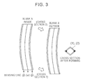
- Fig. 3 illustrates a preformed shape and a cross section after forming of Example 1 of the present invention.
- the length of each side of the tetragonal cross section was 30 mm.
- the length in the longitudinal direction was 300 mm.
- the curvature radius of the bent shape was 1000 mm.
- the width of the flange was 5 mm without trimming of the flange after preforming. Bending lines ⁇ and ⁇ were parallel to each other, and all the bending lines were at the same relative positions on both the blank A and blank B.
- Fig. 4 illustrates a preformed shape and a cross section after forming of Example 2 of the present invention.
- the length in the longitudinal direction was 300 mm.
- the curvature radius of the bent shape was 1000 mm.
- the width of the flange was 3 mm without trimming of the flange after preforming.
- Bending lines ⁇ and ⁇ were of the same curvature, but were not parallel to each other, and all the bending lines were at the same relative positions on both the blank A and blank B.
- Fig. 5 illustrates a preformed shape and a cross section after forming of Example 3 of the present invention.
- the length of the long sides of the rectangular of the cross section was 40 mm, and the short sides 20 mm.
- the length in the longitudinal direction was 300 mm.
- the curvature radius of the bent shape was 1000 mm.
- the width of the flange was 5 mm without trimming of the flange after preforming.
- Bending lines ⁇ and ⁇ were of the same curvature, but were not parallel to each other, and the bending lines ⁇ on the blank A and blank B were tilted in opposite directions to each other, which resulted in the left and right sides of the shape of cross section 1 being reversed in cross section 2.
- Fig. 6 illustrates a preformed shape and a cross section after forming of Example 4 of the present invention.
- the length of each side of the tetragonal cross section was 30 mm.
- the length in the longitudinal direction was 300 mm.
- the curvature radius of the bent shape was 1000 mm.
- the width of the flange after preforming was 5 mm after being trimmed.
- Bending lines ⁇ and ⁇ were parallel to each other and all the bending lines were at the same relative positions on both the blank A and blank B, as in the case of the example 1 of the present invention, but there was not a flange along one of the two bending lines ⁇ .
- the blank A and blank B therefore, were joined along the entire length of the side without a flange by arc welding, after being laid so as to overlap each other.
- Fig. 7 illustrates a preformed shape and a cross section after forming of Comparative Example 1.
- the length of each side of the tetragonal cross section was 30 mm.
- the length in the longitudinal direction was 300 mm.
- the curvature radius of the bent shape was 1000 mm.
- Blanks A and B were formed into the final shape by press forming, and then joined together at the flanges by continuous welding in order to obtain a tetragonal closed section.
- Examples 1 to 4 of the present invention were all able to be formed and welded, and no problems such as cracks or fractures occurred in the welded portions after forming.
- Comparative Example 1 In contrast, twisting, wrinkling and spring back occurred and dimensional accuracy was very poor in the case of Comparative Example 1.
- the matching accuracy, moreover, of the flanges after press forming was so poor that there were gaps at the overlapping portions, which resulted in non-welded portions, and laser welding was impossible. Therefore, the durability of Comparative Example 1 was greatly reduced for the part to be used as a part such as a part for an automobile.
- tetragonal cross section is formed only by bending forming, which enables thin high-strength steel plates to be used.
- a part can be applied to an automobile part, for example, a reinforcement member such as a front pillar, a roof rail and a door impact beam, because the flange width can be made as small as from 3 to 5 mm.
Landscapes
- Engineering & Computer Science (AREA)
- Mechanical Engineering (AREA)
- Shaping Metal By Deep-Drawing, Or The Like (AREA)
- Bending Of Plates, Rods, And Pipes (AREA)
Abstract
Description
- The present invention relates to curvilineal closed parts and methods for manufacturing the same.
- In general, it is known that two parts are joined together after being formed separately to obtain a closed structure part in the fields of automobiles and consumer electrical appliances. Hydroforming and roll forming are known methods for manufacturing curvilineal closed structure parts with flanges of minimized areas.
- All of the peripheral portions of metal plates must be welded before the part is being filled with working fluid in existing hydroforming methods, but the patent literature discloses the following methods.
-
Patent Literature 1 discloses a hydroforming apparatus, a hydroforming method, and a product manufactured by the apparatus and method, which provide high productivity by ensuring good sealing in bulge forming of two or more metal plates laid so as to overlap each other without all of their peripheral portions being welded, and by deep-drawing multiple parts at the same time. -
Patent Literature 2 discloses a method for manufacturing a closed section bent elongated member, including a multistage roll forming process in which strips are formed into a nearly closed structure, a crimping forming process in which the butting sections of the strips are joined together to make a closed section elongated member, and a bending process in which the elongated member is bent in the moving direction of the strips. - Patent Literature 3 discloses a technique for obtaining a product having a twisted portion in closed section out of one piece of material by press forming, and for manufacturing a high-quality lightweight and highly rigid pressed product having a twisted cross section at a low cost.
-
- PTL 1: Japanese Unexamined Patent Application Publication No.
2008-119723 - PTL 2: Japanese Unexamined Patent Application Publication No.
2000-263169 - PTL 3: Japanese Unexamined Patent Application Publication No.
2003-311329 -
Patent Literature 1 discloses the related art relating to a hydroforming technique in which metal plates can be formed without the occurrence of leaking of working fluid by arranging sliding seals on plate holding surfaces to be brought into contact with one or both of the metal plates and non-sliding seals on the plate holding surface to be brought into contact with the other of the metal plates, whereas in existing hydroforming methods all of the peripheral portions of the metal plates must be welded before the part is filled with working fluid. A welding process before hydroforming can be omitted and the time taken to extract the working fluid can be reduced by using this method. The fact remains, however, that this method still uses hydroforming and the equipment cost is very high. In addition, welding is necessary to complete assembly of a product, which brings about the problem of poor surface accuracy. -
Patent Literature 2 discloses the related art relating to a roll forming technique in which a closed section bent elongated member is formed by roll forming and crimping joints are formed on the surfaces in the longitudinal direction in order to omit welding of the butting sections. The cost of this technique may be lower than existing roll forming techniques due to continuous welding for forming a closed section being omitted, but it is difficult to reduce the cost of equipment, because many dies for roll forming are indispensable. - Patent Literature 3 discloses a press forming method. First, flanges are formed on the both sides of a blank which is preformed in this method. Then, the preformed part is pressed into a die which is narrower and closer to the final shape than the preformed part. Finally, the preformed part is pressed into a die which has a twisted portion in the longitudinal direction. In this case, a pressed part with a twisted portion having straight vertical walls can be formed, but, if a pressed part has curved vertical walls, a large rolling deformation is generated in the flanges formed by the preforming, which brings about a problem that it is difficult to match the butting sections to each other.
- As mentioned above, hydroforming and roll forming are known methods for manufacturing closed structure parts, but those methods are disadvantageous compared to press forming in terms of costs of equipment and production, and press forming can be used only for limited cross sectional shapes.
- An object of the present invention is to provide a method for manufacturing polygonal shape closed structure parts with a bent shape in the longitudinal direction by only using press forming, in order to solve the problem of production cost.
- The present invention provides a method for manufacturing a curvilineal closed structure part using two metal plates by performing compression bending after preforming and welding, in order to reduce the number of press forming processes and to improve the accuracy of the part.
- A subject matter of the present invention is as follows.
- A first invention is a method for manufacturing a curvilineal closed structure part using two metal plates. The method includes a press forming process of forming straight or bent folding lines in the longitudinal direction of the metal plates at positions corresponding to a polygonal bent shape and forming a flange at least at one of the ends in the width direction of each plate; a process of forming a closed structure by laying the two plates so as to overlap each other flange to flange, and end to end for ends without flanges and by welding the portions laid so as to overlap each other in the longitudinal direction of the plates; and a process of forming a polygonal shape closed structure with a bent shape in the longitudinal direction with the folding lines formed in the press forming process being used as origins of vertices of the polygonal shape, by holding the both ends of the closed structure with holding units, and by compressing the closed structure in the direction toward the central axis of the closed structure.
- A second invention is the method according to the first invention, further including a process for trimming the flange after the press forming process.
- A third invention is a curvilineal closed structure part manufactured by the method according to the first or the second invention.
- According to the present invention, a curvilineal closed structure part can be manufactured at a lower cost than by existing methods such as hydroforming and roll forming. Furthermore, according to the present invention, a curvilineal shape is formed at a low cost, flanges are minimized to achieve reduced weight, and welded portions are placed closer to the main portion so as to improve rigidity including torsional rigidity. Moreover, it is easy to manufacture parts by using ultra-high strength steel plates, because a predetermined shape can be obtained mainly by bending forming.
-
- [
Fig. 1] Fig. 1 illustrates an example of a curvilineal closed structure part according to the present invention. - [
Fig. 2(a)] Fig. 2(a) illustrates a manufacturing method according to the present invention. - [
Fig. 2(b)] Fig. 2(b) illustrates a manufacturing method according to the present invention. - [
Fig. 2(c)] Fig. 2(c) illustrates a manufacturing method according to the present invention. - [
Fig. 3] Fig. 3 illustrates a preformed shape and a cross section after forming of Example 1 of the present invention. - [
Fig. 4] Fig. 4 illustrates a preformed shape and a cross section after forming of Example 2 of the present invention. - [
Fig. 5] Fig. 5 illustrates a preformed shape and a cross section after forming of Example 3 of the present invention. - [
Fig. 6] Fig. 6 illustrates a preformed shape and a cross section after forming of Example 4 of the present invention. - [
Fig. 7] Fig. 7 illustrates a preformed shape and a cross section after forming of Comparative Example 1. - A manufacturing method according to the present invention will be described below with reference to the drawings.
Fig. 1 illustrates the appearance of a curvilineal closed structure part according to an embodiment of the present invention. The part has a tetragonal cross section, a bent shape in the longitudinal direction, and flanges at the opposing corners of the cross section. The length of each side of the tetragonal cross section is 30 mm. The length in the longitudinal direction is 300 mm. The curvature radius of the bent shape is 1000 mm. The width of the flange is 5 mm. -
Figs. 2(a), 2(b), and 2(c) illustrate a method for manufacturing a curvilineal closed structure part.
Fig. 2(a) illustrates a preforming process as a first process of the method for manufacturing a tetragonal curvilineal closed structure part. Blanks A and B, which form the shape of a tetragon bisected along its diagonal, are made of two metal plates in the process. The cross section is not necessarily a tetragon, and although in this embodiment, a tetragon is explained, the cross section may be another polygonal shape such as a pentagon or a hexagon. - The preforming process gives the metal plates bent portions in advance at positions corresponding to those which are to be vertices of the tetragon cross section.
A bending line α, which is formed by the punch bottom of a preforming die, is formed with a predetermined curvature so that the part is formed into a bent shape in the final compression bending forming process which is the third process. - In addition, portions (flanges at ends of the plate in the width direction) that are to become welding surfaces are also formed so that bending lines β are bent with a predetermined curvature. The bending line α and bending lines βhave the same curvature and center of curvature in
Fig. 2(a) , but it is also possible for the part to be simultaneously given a bent and twisted shape by varying curvature and center of curvature of the bending line α and bending line β respectively. The flanges are formed at both ends in the width direction of the metal plate inFig. 2(a) , but the flange may be formed at least at one of the ends. -
Fig. 2(b) illustrates the second process in which the two metal plates preformed in the first process are laid so as to overlap each other and welded into a single body. The two metal plates preformed in the first process are laid so as to overlap each other with their bulging surfaces facing outward, held with holding units on the both ends, and welded along the vicinities of bending lines β on both ends. The width of the flange is 5 mm inFig. 2(B) . - The both ends in the width direction of the metal plate, moreover, may be trimmed before welding, leaving enough width so that the flanges can be held by holding units, which enables the weight of parts to be reduced by minimizing the sizes of the flanges.
-
Fig. 2B illustrates the case in which the flanges are formed at both ends in the width direction of the metal plate, but, in the case in which a flange is formed only at one end of the metal plate, an end without a flange can be also held with certain holding units (not illustrated), and the vicinity of the end can be subjected to welding. The method for the welding is not necessarily limited to any specified method, and typical methods, such as spot welding, laser welding, arc welding, TIG welding, and seam welding, can be used. The entirety or part of peripheral portions of the metal plates can be continuously welded in the longitudinal direction of the metal plates. -
Fig. 2 (c) illustrates the final process in which the shape of the part is determined by compression bending. Each flange at both ends of the preformed part, after being welded, is held respectively by a holding unit having a shape that follows that of the welding line, and is compressed in the direction towards central axis of the part, which means compression performed by shortening the distance between the holding units. As compression progresses, the angles of the cross section at the welded portions of the part become larger, and the angles of the cross section around the bending lines α become smaller at the same time. The compression amount is adjusted for the angles of the cross section to become the specified values after unloading. -
Fig. 2C illustrates the case in which the flanges are formed at both ends in the width direction of the metal plate, but, in the case with a flange only at one end of the metal plate, the end without a flange can be also held by certain holding units (not illustrated), and formed by compression forming as in the case with flanges at both ends. - As for the metal plate to be applied to manufacture the closed structure part of the present invention, any kind of metal plate, such as steel and non-ferrous materials, can be used. Among steel, normal steel, such as a hot rolled steel plate, a cold rolled steel plate, a coated steel plate which is, for example, galvanized or aluminized, and any kind of steel, from mild steel to ultra-high strength steel, can be used.
-
Figs. 3 to 7 illustrate Examples in which tetragonal curvilineal closed structure parts were formed into various shapes in the preforming process (first process) and welded by laser welding along the bending lines β, and formability and weldability thereof were evaluated after compression bending. A TS 980MPa grade galvannealed steel plate (GA) of 1.2 mm in thickness was used as the material. The zinc coating weight per single side of the blank was 45 g/m2. The output of the laser welder was 3.8 KA. Welding speed was 2.5 m/min. - Blanks A and B, which form the shape of a tetragon bisected by its diagonal, were formed in the preforming process. Examples of the blank A and blank B are illustrated in
Figs. 2(b), 2(c) , and3 to 7 .Fig. 2(c) illustrates a cross section after compression forming. The shapes ofcross section 1 andcross section 2 viewed in the longitudinal direction are illustrated as overlapping each other inFigs. 3 to 7 . Bending lines α and β correspond to the vertices of the polygonal section, and are base lines for bending forming. The bending line β is also the welding base line used when the blank A and blank B are laid so as to overlap each other and then welded. -
Fig. 3 illustrates a preformed shape and a cross section after forming of Example 1 of the present invention. The length of each side of the tetragonal cross section was 30 mm. The length in the longitudinal direction was 300 mm. The curvature radius of the bent shape was 1000 mm. The width of the flange was 5 mm without trimming of the flange after preforming.
Bending lines α and β were parallel to each other, and all the bending lines were at the same relative positions on both the blank A and blank B. -
Fig. 4 illustrates a preformed shape and a cross section after forming of Example 2 of the present invention. The length of the long sides of the tetragonal cross section, which was virtually a kite shape, was 40 mm, and the short sides 20 mm. The length in the longitudinal direction was 300 mm. The curvature radius of the bent shape was 1000 mm. The width of the flange was 3 mm without trimming of the flange after preforming.
Bending lines α and β were of the same curvature, but were not parallel to each other, and all the bending lines were at the same relative positions on both the blank A and blank B. -
Fig. 5 illustrates a preformed shape and a cross section after forming of Example 3 of the present invention. The length of the long sides of the rectangular of the cross section was 40 mm, and the short sides 20 mm. The length in the longitudinal direction was 300 mm. The curvature radius of the bent shape was 1000 mm. The width of the flange was 5 mm without trimming of the flange after preforming.
Bending lines α and β were of the same curvature, but were not parallel to each other, and the bending lines α on the blank A and blank B were tilted in opposite directions to each other, which resulted in the left and right sides of the shape ofcross section 1 being reversed incross section 2. -
Fig. 6 illustrates a preformed shape and a cross section after forming of Example 4 of the present invention. The length of each side of the tetragonal cross section was 30 mm. The length in the longitudinal direction was 300 mm. The curvature radius of the bent shape was 1000 mm. The width of the flange after preforming was 5 mm after being trimmed.
Bending lines α and β were parallel to each other and all the bending lines were at the same relative positions on both the blank A and blank B, as in the case of the example 1 of the present invention, but there was not a flange along one of the two bending lines β. The blank A and blank B, therefore, were joined along the entire length of the side without a flange by arc welding, after being laid so as to overlap each other. -
Fig. 7 illustrates a preformed shape and a cross section after forming of Comparative Example 1. The length of each side of the tetragonal cross section was 30 mm. The length in the longitudinal direction was 300 mm. The curvature radius of the bent shape was 1000 mm.
Blanks A and B were formed into the final shape by press forming, and then joined together at the flanges by continuous welding in order to obtain a tetragonal closed section. - Formability and weldability of each of the tetragonal curvilineal closed structure parts formed in No. 1 to No. 5 described above were evaluated.
Table 1 describes the evaluation results. The evaluation results are indicated as follows: O indicates "was able to be formed" or "was able to be welded"; and x indicates "was not able to be formed" or "was not able to be welded". -
[Table 1] No. Flange Position Formability Weldability Note 1 both sides ○ ○ Example 1 of the present invention 2 both sides ○ ○ Example 2 of the present invention 3 both sides ○ ○ Example 3 of the present invention 4 one side ○ ○ Example 4 of the present invention 5 both sides × (wrinkle, twist) × Comparative Example 1 Notation: ○; "was able to be formed" or "was able to be welded",
×; "was not able to be formed" or "was not able to be welded" - Examples 1 to 4 of the present invention were all able to be formed and welded, and no problems such as cracks or fractures occurred in the welded portions after forming.
- In contrast, twisting, wrinkling and spring back occurred and dimensional accuracy was very poor in the case of Comparative Example 1. The matching accuracy, moreover, of the flanges after press forming was so poor that there were gaps at the overlapping portions, which resulted in non-welded portions, and laser welding was impossible. Therefore, the durability of Comparative Example 1 was greatly reduced for the part to be used as a part such as a part for an automobile.
- According to the present invention, tetragonal cross section is formed only by bending forming, which enables thin high-strength steel plates to be used. For example, such a part can be applied to an automobile part, for example, a reinforcement member such as a front pillar, a roof rail and a door impact beam, because the flange width can be made as small as from 3 to 5 mm.
-
- 1 cross section of closed structure part
- 2 cross section of closed structure part
- α bending line in preforming
- β bending line in preforming
- A preformed part
- B preformed part
Claims (3)
- A method for manufacturing a curvilineal closed structure part using two metal plates, comprising:a press forming process of forming straight or bent folding lines in a longitudinal direction of the metal plates at positions corresponding to a polygonal bent shape, and forming a flange at least at one of the ends of the width direction of each metal plate;a process of forming a closed structure by laying the two metal plates so as to overlap each other flange to flange and end to end for ends without flanges and by welding the portions laid so as to overlap each other in the longitudinal direction of the metal plates; anda process of forming a polygonal shape closed structure with a bent shape in the longitudinal direction with the folding lines formed in the press forming process being used as origins of vertices of the polygonal shape, by holding both ends of the closed structure with holding units, and by compressing the closed structure in the direction toward the central axis of the closed structure.
- The method according to Claim 1, further comprising a process of trimming the flange after the press forming process.
- A curvilineal closed structure part manufactured by the method according to Claim 1 or 2.
Applications Claiming Priority (2)
| Application Number | Priority Date | Filing Date | Title |
|---|---|---|---|
| JP2009213984A JP5640346B2 (en) | 2009-09-16 | 2009-09-16 | Manufacturing method of polygonal closed cross-section structural parts |
| PCT/JP2010/066470 WO2011034203A1 (en) | 2009-09-16 | 2010-09-15 | Curved closed-section structural component and method for manufacturing same |
Publications (3)
| Publication Number | Publication Date |
|---|---|
| EP2478977A1 true EP2478977A1 (en) | 2012-07-25 |
| EP2478977A4 EP2478977A4 (en) | 2014-11-26 |
| EP2478977B1 EP2478977B1 (en) | 2017-01-04 |
Family
ID=43758799
Family Applications (1)
| Application Number | Title | Priority Date | Filing Date |
|---|---|---|---|
| EP10817315.4A Active EP2478977B1 (en) | 2009-09-16 | 2010-09-15 | Method for manufacturing a curved closed-section structural component |
Country Status (7)
| Country | Link |
|---|---|
| US (1) | US9009970B2 (en) |
| EP (1) | EP2478977B1 (en) |
| JP (1) | JP5640346B2 (en) |
| KR (2) | KR20120054055A (en) |
| CN (1) | CN102481616B (en) |
| CA (1) | CA2773034C (en) |
| WO (1) | WO2011034203A1 (en) |
Cited By (1)
| Publication number | Priority date | Publication date | Assignee | Title |
|---|---|---|---|---|
| EP2837437A4 (en) * | 2012-04-13 | 2015-11-04 | Jfe Steel Corp | DEVICE AND METHOD FOR PRODUCING COMPONENT WITH NON-CLOSED CROSS SECTION WITHOUT WING POSSESSING CURVED SHAPE |
Families Citing this family (10)
| Publication number | Priority date | Publication date | Assignee | Title |
|---|---|---|---|---|
| TWI477330B (en) * | 2012-04-13 | 2015-03-21 | Jfe Steel Corp | Method for manufacturing curvilineal closed structure parts without flange and apparatus for the same |
| TWI477329B (en) * | 2012-04-13 | 2015-03-21 | Jfe Steel Corp | Method for manufacturing curvilineal closed structure parts and apparatus for the same |
| WO2013153681A1 (en) | 2012-04-13 | 2013-10-17 | Jfeスチール株式会社 | Device and method for producing closed-cross-section-structure component |
| JP5454619B2 (en) * | 2012-05-28 | 2014-03-26 | Jfeスチール株式会社 | Closed-section structure forming method and closed-section structure forming apparatus |
| JP5966617B2 (en) * | 2012-05-28 | 2016-08-10 | Jfeスチール株式会社 | Closed-section structure forming method and closed-section structure forming apparatus |
| JP5761275B2 (en) | 2013-08-26 | 2015-08-12 | Jfeスチール株式会社 | Polygonal closed cross-section structural part manufacturing method having bent shape and polygonal closed cross-section structural part manufactured by the method |
| JP5866324B2 (en) * | 2013-09-30 | 2016-02-17 | 本田技研工業株式会社 | Hydroform molding method for hollow structural parts |
| CN109996616A (en) * | 2016-11-30 | 2019-07-09 | 爱信轻金属株式会社 | Structural member |
| FR3065488B1 (en) * | 2017-04-20 | 2019-06-28 | Faurecia Systemes D'echappement | EXHAUST LINE ELEMENT AND METHOD OF MANUFACTURING SUCH A MEMBER |
| CN116140438B (en) * | 2022-12-06 | 2025-08-22 | 中铁上海工程局集团有限公司 | A method for forming and controlling a special-shaped curved panel unit |
Family Cites Families (12)
| Publication number | Priority date | Publication date | Assignee | Title |
|---|---|---|---|---|
| FR531221A (en) | 1917-11-05 | 1922-01-09 | Zeppelin Luftschiffbau | Hollow bar in two parts, in particular for reinforcing all beams or light members |
| AU6392473A (en) | 1973-02-20 | 1975-06-26 | Wellington R F | Pipe offset |
| JP3801805B2 (en) | 1999-03-16 | 2006-07-26 | 本田技研工業株式会社 | Closed section curved long material |
| JP2001191112A (en) * | 2000-01-07 | 2001-07-17 | Toyota Motor Corp | Method and apparatus for forming tubular member having rectangular cross section |
| US6877349B2 (en) * | 2000-08-17 | 2005-04-12 | Industrial Origami, Llc | Method for precision bending of sheet of materials, slit sheets fabrication process |
| DE10101927B4 (en) | 2001-01-16 | 2006-05-24 | Wagon Automotive Gmbh | Structural component of a motor vehicle body and method for producing such a structural component |
| FI110238B (en) * | 2001-01-31 | 2002-12-31 | Innowork Oy | Process for making a box beam and according to the method a box beam and structural part for a box beam |
| FR2823006A1 (en) * | 2001-04-03 | 2002-10-04 | Imphy Ugine Precision | Shadow mask support frame for color cathode ray tube, has joining portions that contact with internal face of flat wall perpendicular to reference plane of frame, to abut with end uprights |
| JP2003311329A (en) | 2002-04-25 | 2003-11-05 | Toyota Motor Corp | Rolled cross section press die, roll cross section pressing method, and roll cross section press molded product |
| JP4581473B2 (en) * | 2004-04-28 | 2010-11-17 | 日産自動車株式会社 | Hydraulic molding method and hydraulic molding apparatus |
| JP4826436B2 (en) | 2006-11-13 | 2011-11-30 | 住友金属工業株式会社 | Metal plate hydroform processing apparatus, processing method, and processed products using them |
| DE102008037612B4 (en) * | 2008-11-28 | 2014-01-23 | Thyssenkrupp Steel Europe Ag | Method and tool set for the production of flanged, high-dimensional and deep-drawn half-shells |
-
2009
- 2009-09-16 JP JP2009213984A patent/JP5640346B2/en active Active
-
2010
- 2010-09-15 EP EP10817315.4A patent/EP2478977B1/en active Active
- 2010-09-15 CN CN201080040501.2A patent/CN102481616B/en active Active
- 2010-09-15 CA CA2773034A patent/CA2773034C/en not_active Expired - Fee Related
- 2010-09-15 KR KR1020127006025A patent/KR20120054055A/en not_active Ceased
- 2010-09-15 WO PCT/JP2010/066470 patent/WO2011034203A1/en not_active Ceased
- 2010-09-15 KR KR1020157002388A patent/KR101613404B1/en active Active
- 2010-09-15 US US13/391,850 patent/US9009970B2/en active Active
Cited By (1)
| Publication number | Priority date | Publication date | Assignee | Title |
|---|---|---|---|---|
| EP2837437A4 (en) * | 2012-04-13 | 2015-11-04 | Jfe Steel Corp | DEVICE AND METHOD FOR PRODUCING COMPONENT WITH NON-CLOSED CROSS SECTION WITHOUT WING POSSESSING CURVED SHAPE |
Also Published As
| Publication number | Publication date |
|---|---|
| US20120204993A1 (en) | 2012-08-16 |
| WO2011034203A1 (en) | 2011-03-24 |
| CA2773034A1 (en) | 2011-03-24 |
| EP2478977B1 (en) | 2017-01-04 |
| US9009970B2 (en) | 2015-04-21 |
| JP5640346B2 (en) | 2014-12-17 |
| CA2773034C (en) | 2014-04-29 |
| KR20150017776A (en) | 2015-02-17 |
| KR20120054055A (en) | 2012-05-29 |
| CN102481616B (en) | 2015-12-02 |
| EP2478977A4 (en) | 2014-11-26 |
| JP2011062713A (en) | 2011-03-31 |
| KR101613404B1 (en) | 2016-04-18 |
| CN102481616A (en) | 2012-05-30 |
Similar Documents
| Publication | Publication Date | Title |
|---|---|---|
| EP2478977B1 (en) | Method for manufacturing a curved closed-section structural component | |
| EP2896467B1 (en) | Method for producing curved article | |
| US10239105B2 (en) | Blank steel plate, production method and production device therefor, and production method for press-formed product using blank steel plate | |
| US20170232492A1 (en) | Method of manufacturing press-formed product, and press-formed product | |
| US10124387B2 (en) | Press-molded product, press-molded product producing method, and press-molded product producing apparatus | |
| EP4119250A1 (en) | Method for manufacturing pressed component, metal plate for press-molding, and high-tensile steel plate | |
| EP3434501A1 (en) | Door inner panel and method for manufacturing door inner panel | |
| KR101579028B1 (en) | Method for manufacturing closed-structure part and apparatus for the same | |
| EP2857117B1 (en) | Method of forming structure having closed cross section, and device for forming structure having closed cross section | |
| EP3165297B1 (en) | Bending method | |
| EP3895824B1 (en) | Press forming method | |
| US20050244667A1 (en) | Hybrid-produced sheet metal element and method of producing same | |
| US7484298B2 (en) | Method for forming a complex-shaped tubular structure | |
| CN104364026B (en) | There is the manufacture method and the device that close cross section structure part without flange of curved shape | |
| US10011312B2 (en) | Process for forming reinforced rocker panel assembly | |
| CN113631466A (en) | Joint structure of vehicle body frame member, vehicle body frame member, and manufacturing method of the vehicle body frame member | |
| EP4321269A1 (en) | Press forming method | |
| EP4644014A1 (en) | Structural member and method for manufacturing same | |
| US5672216A (en) | Distortion free heat treated metal stampings | |
| EP4644214A1 (en) | Superimposing structural member for automobile body, and method for manufacturing same | |
| JP7381965B2 (en) | Steel parts and their manufacturing method | |
| KR20160114309A (en) | Roll forming method | |
| EP4620591A1 (en) | Press molded article and method for manufacturing press molded article | |
| EP4454777A1 (en) | Press-molding method and press-molded article manufacturing method | |
| US20050217098A1 (en) | Device and process for producing rolled sections |
Legal Events
| Date | Code | Title | Description |
|---|---|---|---|
| PUAI | Public reference made under article 153(3) epc to a published international application that has entered the european phase |
Free format text: ORIGINAL CODE: 0009012 |
|
| 17P | Request for examination filed |
Effective date: 20120410 |
|
| AK | Designated contracting states |
Kind code of ref document: A1 Designated state(s): AL AT BE BG CH CY CZ DE DK EE ES FI FR GB GR HR HU IE IS IT LI LT LU LV MC MK MT NL NO PL PT RO SE SI SK SM TR |
|
| DAX | Request for extension of the european patent (deleted) | ||
| A4 | Supplementary search report drawn up and despatched |
Effective date: 20141027 |
|
| RIC1 | Information provided on ipc code assigned before grant |
Ipc: B21D 47/01 20060101ALI20141021BHEP Ipc: B21D 51/16 20060101AFI20141021BHEP Ipc: B21D 51/18 20060101ALI20141021BHEP Ipc: B21D 5/01 20060101ALI20141021BHEP |
|
| 17Q | First examination report despatched |
Effective date: 20151008 |
|
| GRAP | Despatch of communication of intention to grant a patent |
Free format text: ORIGINAL CODE: EPIDOSNIGR1 |
|
| RIC1 | Information provided on ipc code assigned before grant |
Ipc: B21D 5/01 20060101ALI20160718BHEP Ipc: B21D 51/16 20060101AFI20160718BHEP Ipc: B21D 51/18 20060101ALI20160718BHEP Ipc: B21D 47/01 20060101ALI20160718BHEP |
|
| INTG | Intention to grant announced |
Effective date: 20160810 |
|
| GRAS | Grant fee paid |
Free format text: ORIGINAL CODE: EPIDOSNIGR3 |
|
| GRAA | (expected) grant |
Free format text: ORIGINAL CODE: 0009210 |
|
| AK | Designated contracting states |
Kind code of ref document: B1 Designated state(s): AL AT BE BG CH CY CZ DE DK EE ES FI FR GB GR HR HU IE IS IT LI LT LU LV MC MK MT NL NO PL PT RO SE SI SK SM TR |
|
| REG | Reference to a national code |
Ref country code: GB Ref legal event code: FG4D |
|
| REG | Reference to a national code |
Ref country code: CH Ref legal event code: EP |
|
| REG | Reference to a national code |
Ref country code: AT Ref legal event code: REF Ref document number: 858733 Country of ref document: AT Kind code of ref document: T Effective date: 20170115 |
|
| REG | Reference to a national code |
Ref country code: IE Ref legal event code: FG4D |
|
| REG | Reference to a national code |
Ref country code: DE Ref legal event code: R096 Ref document number: 602010039397 Country of ref document: DE |
|
| REG | Reference to a national code |
Ref country code: LT Ref legal event code: MG4D Ref country code: NL Ref legal event code: MP Effective date: 20170104 |
|
| REG | Reference to a national code |
Ref country code: AT Ref legal event code: MK05 Ref document number: 858733 Country of ref document: AT Kind code of ref document: T Effective date: 20170104 |
|
| PG25 | Lapsed in a contracting state [announced via postgrant information from national office to epo] |
Ref country code: NL Free format text: LAPSE BECAUSE OF FAILURE TO SUBMIT A TRANSLATION OF THE DESCRIPTION OR TO PAY THE FEE WITHIN THE PRESCRIBED TIME-LIMIT Effective date: 20170104 |
|
| PG25 | Lapsed in a contracting state [announced via postgrant information from national office to epo] |
Ref country code: FI Free format text: LAPSE BECAUSE OF FAILURE TO SUBMIT A TRANSLATION OF THE DESCRIPTION OR TO PAY THE FEE WITHIN THE PRESCRIBED TIME-LIMIT Effective date: 20170104 Ref country code: IS Free format text: LAPSE BECAUSE OF FAILURE TO SUBMIT A TRANSLATION OF THE DESCRIPTION OR TO PAY THE FEE WITHIN THE PRESCRIBED TIME-LIMIT Effective date: 20170504 Ref country code: GR Free format text: LAPSE BECAUSE OF FAILURE TO SUBMIT A TRANSLATION OF THE DESCRIPTION OR TO PAY THE FEE WITHIN THE PRESCRIBED TIME-LIMIT Effective date: 20170405 Ref country code: LT Free format text: LAPSE BECAUSE OF FAILURE TO SUBMIT A TRANSLATION OF THE DESCRIPTION OR TO PAY THE FEE WITHIN THE PRESCRIBED TIME-LIMIT Effective date: 20170104 Ref country code: HR Free format text: LAPSE BECAUSE OF FAILURE TO SUBMIT A TRANSLATION OF THE DESCRIPTION OR TO PAY THE FEE WITHIN THE PRESCRIBED TIME-LIMIT Effective date: 20170104 Ref country code: NO Free format text: LAPSE BECAUSE OF FAILURE TO SUBMIT A TRANSLATION OF THE DESCRIPTION OR TO PAY THE FEE WITHIN THE PRESCRIBED TIME-LIMIT Effective date: 20170404 |
|
| PG25 | Lapsed in a contracting state [announced via postgrant information from national office to epo] |
Ref country code: PT Free format text: LAPSE BECAUSE OF FAILURE TO SUBMIT A TRANSLATION OF THE DESCRIPTION OR TO PAY THE FEE WITHIN THE PRESCRIBED TIME-LIMIT Effective date: 20170504 Ref country code: LV Free format text: LAPSE BECAUSE OF FAILURE TO SUBMIT A TRANSLATION OF THE DESCRIPTION OR TO PAY THE FEE WITHIN THE PRESCRIBED TIME-LIMIT Effective date: 20170104 Ref country code: ES Free format text: LAPSE BECAUSE OF FAILURE TO SUBMIT A TRANSLATION OF THE DESCRIPTION OR TO PAY THE FEE WITHIN THE PRESCRIBED TIME-LIMIT Effective date: 20170104 Ref country code: AT Free format text: LAPSE BECAUSE OF FAILURE TO SUBMIT A TRANSLATION OF THE DESCRIPTION OR TO PAY THE FEE WITHIN THE PRESCRIBED TIME-LIMIT Effective date: 20170104 Ref country code: PL Free format text: LAPSE BECAUSE OF FAILURE TO SUBMIT A TRANSLATION OF THE DESCRIPTION OR TO PAY THE FEE WITHIN THE PRESCRIBED TIME-LIMIT Effective date: 20170104 Ref country code: SE Free format text: LAPSE BECAUSE OF FAILURE TO SUBMIT A TRANSLATION OF THE DESCRIPTION OR TO PAY THE FEE WITHIN THE PRESCRIBED TIME-LIMIT Effective date: 20170104 Ref country code: BG Free format text: LAPSE BECAUSE OF FAILURE TO SUBMIT A TRANSLATION OF THE DESCRIPTION OR TO PAY THE FEE WITHIN THE PRESCRIBED TIME-LIMIT Effective date: 20170404 |
|
| REG | Reference to a national code |
Ref country code: FR Ref legal event code: PLFP Year of fee payment: 8 |
|
| REG | Reference to a national code |
Ref country code: DE Ref legal event code: R097 Ref document number: 602010039397 Country of ref document: DE |
|
| PG25 | Lapsed in a contracting state [announced via postgrant information from national office to epo] |
Ref country code: SK Free format text: LAPSE BECAUSE OF FAILURE TO SUBMIT A TRANSLATION OF THE DESCRIPTION OR TO PAY THE FEE WITHIN THE PRESCRIBED TIME-LIMIT Effective date: 20170104 Ref country code: EE Free format text: LAPSE BECAUSE OF FAILURE TO SUBMIT A TRANSLATION OF THE DESCRIPTION OR TO PAY THE FEE WITHIN THE PRESCRIBED TIME-LIMIT Effective date: 20170104 Ref country code: IT Free format text: LAPSE BECAUSE OF FAILURE TO SUBMIT A TRANSLATION OF THE DESCRIPTION OR TO PAY THE FEE WITHIN THE PRESCRIBED TIME-LIMIT Effective date: 20170104 Ref country code: CZ Free format text: LAPSE BECAUSE OF FAILURE TO SUBMIT A TRANSLATION OF THE DESCRIPTION OR TO PAY THE FEE WITHIN THE PRESCRIBED TIME-LIMIT Effective date: 20170104 Ref country code: RO Free format text: LAPSE BECAUSE OF FAILURE TO SUBMIT A TRANSLATION OF THE DESCRIPTION OR TO PAY THE FEE WITHIN THE PRESCRIBED TIME-LIMIT Effective date: 20170104 |
|
| PLBE | No opposition filed within time limit |
Free format text: ORIGINAL CODE: 0009261 |
|
| STAA | Information on the status of an ep patent application or granted ep patent |
Free format text: STATUS: NO OPPOSITION FILED WITHIN TIME LIMIT |
|
| PG25 | Lapsed in a contracting state [announced via postgrant information from national office to epo] |
Ref country code: SM Free format text: LAPSE BECAUSE OF FAILURE TO SUBMIT A TRANSLATION OF THE DESCRIPTION OR TO PAY THE FEE WITHIN THE PRESCRIBED TIME-LIMIT Effective date: 20170104 Ref country code: DK Free format text: LAPSE BECAUSE OF FAILURE TO SUBMIT A TRANSLATION OF THE DESCRIPTION OR TO PAY THE FEE WITHIN THE PRESCRIBED TIME-LIMIT Effective date: 20170104 |
|
| 26N | No opposition filed |
Effective date: 20171005 |
|
| PG25 | Lapsed in a contracting state [announced via postgrant information from national office to epo] |
Ref country code: SI Free format text: LAPSE BECAUSE OF FAILURE TO SUBMIT A TRANSLATION OF THE DESCRIPTION OR TO PAY THE FEE WITHIN THE PRESCRIBED TIME-LIMIT Effective date: 20170104 |
|
| REG | Reference to a national code |
Ref country code: CH Ref legal event code: PL |
|
| PG25 | Lapsed in a contracting state [announced via postgrant information from national office to epo] |
Ref country code: MC Free format text: LAPSE BECAUSE OF FAILURE TO SUBMIT A TRANSLATION OF THE DESCRIPTION OR TO PAY THE FEE WITHIN THE PRESCRIBED TIME-LIMIT Effective date: 20170104 |
|
| REG | Reference to a national code |
Ref country code: IE Ref legal event code: MM4A |
|
| REG | Reference to a national code |
Ref country code: BE Ref legal event code: MM Effective date: 20170930 |
|
| PG25 | Lapsed in a contracting state [announced via postgrant information from national office to epo] |
Ref country code: LU Free format text: LAPSE BECAUSE OF NON-PAYMENT OF DUE FEES Effective date: 20170915 |
|
| PG25 | Lapsed in a contracting state [announced via postgrant information from national office to epo] |
Ref country code: CH Free format text: LAPSE BECAUSE OF NON-PAYMENT OF DUE FEES Effective date: 20170930 Ref country code: LI Free format text: LAPSE BECAUSE OF NON-PAYMENT OF DUE FEES Effective date: 20170930 Ref country code: IE Free format text: LAPSE BECAUSE OF NON-PAYMENT OF DUE FEES Effective date: 20170915 |
|
| REG | Reference to a national code |
Ref country code: FR Ref legal event code: PLFP Year of fee payment: 9 |
|
| PG25 | Lapsed in a contracting state [announced via postgrant information from national office to epo] |
Ref country code: BE Free format text: LAPSE BECAUSE OF NON-PAYMENT OF DUE FEES Effective date: 20170930 |
|
| PG25 | Lapsed in a contracting state [announced via postgrant information from national office to epo] |
Ref country code: MT Free format text: LAPSE BECAUSE OF NON-PAYMENT OF DUE FEES Effective date: 20170915 |
|
| PG25 | Lapsed in a contracting state [announced via postgrant information from national office to epo] |
Ref country code: HU Free format text: LAPSE BECAUSE OF FAILURE TO SUBMIT A TRANSLATION OF THE DESCRIPTION OR TO PAY THE FEE WITHIN THE PRESCRIBED TIME-LIMIT; INVALID AB INITIO Effective date: 20100915 |
|
| PG25 | Lapsed in a contracting state [announced via postgrant information from national office to epo] |
Ref country code: CY Free format text: LAPSE BECAUSE OF NON-PAYMENT OF DUE FEES Effective date: 20170104 |
|
| PG25 | Lapsed in a contracting state [announced via postgrant information from national office to epo] |
Ref country code: MK Free format text: LAPSE BECAUSE OF FAILURE TO SUBMIT A TRANSLATION OF THE DESCRIPTION OR TO PAY THE FEE WITHIN THE PRESCRIBED TIME-LIMIT Effective date: 20170104 |
|
| PG25 | Lapsed in a contracting state [announced via postgrant information from national office to epo] |
Ref country code: TR Free format text: LAPSE BECAUSE OF FAILURE TO SUBMIT A TRANSLATION OF THE DESCRIPTION OR TO PAY THE FEE WITHIN THE PRESCRIBED TIME-LIMIT Effective date: 20170104 |
|
| PG25 | Lapsed in a contracting state [announced via postgrant information from national office to epo] |
Ref country code: AL Free format text: LAPSE BECAUSE OF FAILURE TO SUBMIT A TRANSLATION OF THE DESCRIPTION OR TO PAY THE FEE WITHIN THE PRESCRIBED TIME-LIMIT Effective date: 20170104 |
|
| PGFP | Annual fee paid to national office [announced via postgrant information from national office to epo] |
Ref country code: GB Payment date: 20220728 Year of fee payment: 13 |
|
| GBPC | Gb: european patent ceased through non-payment of renewal fee |
Effective date: 20230915 |
|
| PG25 | Lapsed in a contracting state [announced via postgrant information from national office to epo] |
Ref country code: GB Free format text: LAPSE BECAUSE OF NON-PAYMENT OF DUE FEES Effective date: 20230915 |
|
| PG25 | Lapsed in a contracting state [announced via postgrant information from national office to epo] |
Ref country code: GB Free format text: LAPSE BECAUSE OF NON-PAYMENT OF DUE FEES Effective date: 20230915 |
|
| PGFP | Annual fee paid to national office [announced via postgrant information from national office to epo] |
Ref country code: DE Payment date: 20250730 Year of fee payment: 16 |
|
| PGFP | Annual fee paid to national office [announced via postgrant information from national office to epo] |
Ref country code: FR Payment date: 20250808 Year of fee payment: 16 |