EP2478873B1 - Moment induced total arthroplasty prosthetic - Google Patents
Moment induced total arthroplasty prosthetic Download PDFInfo
- Publication number
- EP2478873B1 EP2478873B1 EP12164378.7A EP12164378A EP2478873B1 EP 2478873 B1 EP2478873 B1 EP 2478873B1 EP 12164378 A EP12164378 A EP 12164378A EP 2478873 B1 EP2478873 B1 EP 2478873B1
- Authority
- EP
- European Patent Office
- Prior art keywords
- prosthetic
- medial
- insert
- lateral
- condyle
- Prior art date
- Legal status (The legal status is an assumption and is not a legal conclusion. Google has not performed a legal analysis and makes no representation as to the accuracy of the status listed.)
- Active
Links
- 238000011882 arthroplasty Methods 0.000 title 1
- 210000000629 knee joint Anatomy 0.000 claims description 10
- 230000000087 stabilizing effect Effects 0.000 claims description 9
- 230000003019 stabilising effect Effects 0.000 claims description 5
- 238000011883 total knee arthroplasty Methods 0.000 description 71
- 210000003127 knee Anatomy 0.000 description 50
- 239000004698 Polyethylene Substances 0.000 description 21
- -1 polyethylene Polymers 0.000 description 21
- 229920000573 polyethylene Polymers 0.000 description 21
- 238000004458 analytical method Methods 0.000 description 17
- 238000005096 rolling process Methods 0.000 description 14
- 210000000689 upper leg Anatomy 0.000 description 12
- 210000002303 tibia Anatomy 0.000 description 11
- 230000007246 mechanism Effects 0.000 description 9
- 239000007943 implant Substances 0.000 description 8
- 210000003041 ligament Anatomy 0.000 description 6
- 238000001727 in vivo Methods 0.000 description 5
- 238000013178 mathematical model Methods 0.000 description 5
- 210000002967 posterior cruciate ligament Anatomy 0.000 description 5
- 238000010276 construction Methods 0.000 description 4
- 230000001133 acceleration Effects 0.000 description 3
- 230000007423 decrease Effects 0.000 description 3
- 238000010586 diagram Methods 0.000 description 3
- 238000001356 surgical procedure Methods 0.000 description 3
- 230000003247 decreasing effect Effects 0.000 description 2
- 230000005484 gravity Effects 0.000 description 2
- 238000000034 method Methods 0.000 description 2
- 210000003205 muscle Anatomy 0.000 description 2
- 210000004417 patella Anatomy 0.000 description 2
- 230000006641 stabilisation Effects 0.000 description 2
- 230000005856 abnormality Effects 0.000 description 1
- 230000004075 alteration Effects 0.000 description 1
- 210000004439 collateral ligament Anatomy 0.000 description 1
- 230000000295 complement effect Effects 0.000 description 1
- 230000000694 effects Effects 0.000 description 1
- 230000005021 gait Effects 0.000 description 1
- 230000014759 maintenance of location Effects 0.000 description 1
- 230000002028 premature Effects 0.000 description 1
Images


Classifications
-
- A—HUMAN NECESSITIES
- A61—MEDICAL OR VETERINARY SCIENCE; HYGIENE
- A61F—FILTERS IMPLANTABLE INTO BLOOD VESSELS; PROSTHESES; DEVICES PROVIDING PATENCY TO, OR PREVENTING COLLAPSING OF, TUBULAR STRUCTURES OF THE BODY, e.g. STENTS; ORTHOPAEDIC, NURSING OR CONTRACEPTIVE DEVICES; FOMENTATION; TREATMENT OR PROTECTION OF EYES OR EARS; BANDAGES, DRESSINGS OR ABSORBENT PADS; FIRST-AID KITS
- A61F2/00—Filters implantable into blood vessels; Prostheses, i.e. artificial substitutes or replacements for parts of the body; Appliances for connecting them with the body; Devices providing patency to, or preventing collapsing of, tubular structures of the body, e.g. stents
- A61F2/02—Prostheses implantable into the body
- A61F2/30—Joints
- A61F2/38—Joints for elbows or knees
- A61F2/3836—Special connection between upper and lower leg, e.g. constrained
-
- A—HUMAN NECESSITIES
- A61—MEDICAL OR VETERINARY SCIENCE; HYGIENE
- A61F—FILTERS IMPLANTABLE INTO BLOOD VESSELS; PROSTHESES; DEVICES PROVIDING PATENCY TO, OR PREVENTING COLLAPSING OF, TUBULAR STRUCTURES OF THE BODY, e.g. STENTS; ORTHOPAEDIC, NURSING OR CONTRACEPTIVE DEVICES; FOMENTATION; TREATMENT OR PROTECTION OF EYES OR EARS; BANDAGES, DRESSINGS OR ABSORBENT PADS; FIRST-AID KITS
- A61F2/00—Filters implantable into blood vessels; Prostheses, i.e. artificial substitutes or replacements for parts of the body; Appliances for connecting them with the body; Devices providing patency to, or preventing collapsing of, tubular structures of the body, e.g. stents
- A61F2/02—Prostheses implantable into the body
- A61F2/30—Joints
- A61F2/38—Joints for elbows or knees
- A61F2/3868—Joints for elbows or knees with sliding tibial bearing
-
- A—HUMAN NECESSITIES
- A61—MEDICAL OR VETERINARY SCIENCE; HYGIENE
- A61F—FILTERS IMPLANTABLE INTO BLOOD VESSELS; PROSTHESES; DEVICES PROVIDING PATENCY TO, OR PREVENTING COLLAPSING OF, TUBULAR STRUCTURES OF THE BODY, e.g. STENTS; ORTHOPAEDIC, NURSING OR CONTRACEPTIVE DEVICES; FOMENTATION; TREATMENT OR PROTECTION OF EYES OR EARS; BANDAGES, DRESSINGS OR ABSORBENT PADS; FIRST-AID KITS
- A61F2/00—Filters implantable into blood vessels; Prostheses, i.e. artificial substitutes or replacements for parts of the body; Appliances for connecting them with the body; Devices providing patency to, or preventing collapsing of, tubular structures of the body, e.g. stents
- A61F2/02—Prostheses implantable into the body
- A61F2/30—Joints
- A61F2/38—Joints for elbows or knees
- A61F2/3886—Joints for elbows or knees for stabilising knees against anterior or lateral dislocations
-
- A—HUMAN NECESSITIES
- A61—MEDICAL OR VETERINARY SCIENCE; HYGIENE
- A61F—FILTERS IMPLANTABLE INTO BLOOD VESSELS; PROSTHESES; DEVICES PROVIDING PATENCY TO, OR PREVENTING COLLAPSING OF, TUBULAR STRUCTURES OF THE BODY, e.g. STENTS; ORTHOPAEDIC, NURSING OR CONTRACEPTIVE DEVICES; FOMENTATION; TREATMENT OR PROTECTION OF EYES OR EARS; BANDAGES, DRESSINGS OR ABSORBENT PADS; FIRST-AID KITS
- A61F2/00—Filters implantable into blood vessels; Prostheses, i.e. artificial substitutes or replacements for parts of the body; Appliances for connecting them with the body; Devices providing patency to, or preventing collapsing of, tubular structures of the body, e.g. stents
- A61F2/02—Prostheses implantable into the body
- A61F2/30—Joints
- A61F2/38—Joints for elbows or knees
- A61F2/3859—Femoral components
-
- A—HUMAN NECESSITIES
- A61—MEDICAL OR VETERINARY SCIENCE; HYGIENE
- A61F—FILTERS IMPLANTABLE INTO BLOOD VESSELS; PROSTHESES; DEVICES PROVIDING PATENCY TO, OR PREVENTING COLLAPSING OF, TUBULAR STRUCTURES OF THE BODY, e.g. STENTS; ORTHOPAEDIC, NURSING OR CONTRACEPTIVE DEVICES; FOMENTATION; TREATMENT OR PROTECTION OF EYES OR EARS; BANDAGES, DRESSINGS OR ABSORBENT PADS; FIRST-AID KITS
- A61F2/00—Filters implantable into blood vessels; Prostheses, i.e. artificial substitutes or replacements for parts of the body; Appliances for connecting them with the body; Devices providing patency to, or preventing collapsing of, tubular structures of the body, e.g. stents
- A61F2/02—Prostheses implantable into the body
- A61F2/30—Joints
- A61F2/38—Joints for elbows or knees
- A61F2/389—Tibial components
-
- A—HUMAN NECESSITIES
- A61—MEDICAL OR VETERINARY SCIENCE; HYGIENE
- A61F—FILTERS IMPLANTABLE INTO BLOOD VESSELS; PROSTHESES; DEVICES PROVIDING PATENCY TO, OR PREVENTING COLLAPSING OF, TUBULAR STRUCTURES OF THE BODY, e.g. STENTS; ORTHOPAEDIC, NURSING OR CONTRACEPTIVE DEVICES; FOMENTATION; TREATMENT OR PROTECTION OF EYES OR EARS; BANDAGES, DRESSINGS OR ABSORBENT PADS; FIRST-AID KITS
- A61F2/00—Filters implantable into blood vessels; Prostheses, i.e. artificial substitutes or replacements for parts of the body; Appliances for connecting them with the body; Devices providing patency to, or preventing collapsing of, tubular structures of the body, e.g. stents
- A61F2/02—Prostheses implantable into the body
- A61F2/28—Bones
- A61F2002/2892—Tibia
-
- A—HUMAN NECESSITIES
- A61—MEDICAL OR VETERINARY SCIENCE; HYGIENE
- A61F—FILTERS IMPLANTABLE INTO BLOOD VESSELS; PROSTHESES; DEVICES PROVIDING PATENCY TO, OR PREVENTING COLLAPSING OF, TUBULAR STRUCTURES OF THE BODY, e.g. STENTS; ORTHOPAEDIC, NURSING OR CONTRACEPTIVE DEVICES; FOMENTATION; TREATMENT OR PROTECTION OF EYES OR EARS; BANDAGES, DRESSINGS OR ABSORBENT PADS; FIRST-AID KITS
- A61F2/00—Filters implantable into blood vessels; Prostheses, i.e. artificial substitutes or replacements for parts of the body; Appliances for connecting them with the body; Devices providing patency to, or preventing collapsing of, tubular structures of the body, e.g. stents
- A61F2/02—Prostheses implantable into the body
- A61F2/30—Joints
- A61F2002/30001—Additional features of subject-matter classified in A61F2/28, A61F2/30 and subgroups thereof
- A61F2002/30003—Material related properties of the prosthesis or of a coating on the prosthesis
- A61F2002/30004—Material related properties of the prosthesis or of a coating on the prosthesis the prosthesis being made from materials having different values of a given property at different locations within the same prosthesis
- A61F2002/30016—Material related properties of the prosthesis or of a coating on the prosthesis the prosthesis being made from materials having different values of a given property at different locations within the same prosthesis differing in hardness, e.g. Vickers, Shore, Brinell
-
- A—HUMAN NECESSITIES
- A61—MEDICAL OR VETERINARY SCIENCE; HYGIENE
- A61F—FILTERS IMPLANTABLE INTO BLOOD VESSELS; PROSTHESES; DEVICES PROVIDING PATENCY TO, OR PREVENTING COLLAPSING OF, TUBULAR STRUCTURES OF THE BODY, e.g. STENTS; ORTHOPAEDIC, NURSING OR CONTRACEPTIVE DEVICES; FOMENTATION; TREATMENT OR PROTECTION OF EYES OR EARS; BANDAGES, DRESSINGS OR ABSORBENT PADS; FIRST-AID KITS
- A61F2/00—Filters implantable into blood vessels; Prostheses, i.e. artificial substitutes or replacements for parts of the body; Appliances for connecting them with the body; Devices providing patency to, or preventing collapsing of, tubular structures of the body, e.g. stents
- A61F2/02—Prostheses implantable into the body
- A61F2/30—Joints
- A61F2002/30001—Additional features of subject-matter classified in A61F2/28, A61F2/30 and subgroups thereof
- A61F2002/30108—Shapes
- A61F2002/30199—Three-dimensional shapes
-
- A—HUMAN NECESSITIES
- A61—MEDICAL OR VETERINARY SCIENCE; HYGIENE
- A61F—FILTERS IMPLANTABLE INTO BLOOD VESSELS; PROSTHESES; DEVICES PROVIDING PATENCY TO, OR PREVENTING COLLAPSING OF, TUBULAR STRUCTURES OF THE BODY, e.g. STENTS; ORTHOPAEDIC, NURSING OR CONTRACEPTIVE DEVICES; FOMENTATION; TREATMENT OR PROTECTION OF EYES OR EARS; BANDAGES, DRESSINGS OR ABSORBENT PADS; FIRST-AID KITS
- A61F2/00—Filters implantable into blood vessels; Prostheses, i.e. artificial substitutes or replacements for parts of the body; Appliances for connecting them with the body; Devices providing patency to, or preventing collapsing of, tubular structures of the body, e.g. stents
- A61F2/02—Prostheses implantable into the body
- A61F2/30—Joints
- A61F2002/30001—Additional features of subject-matter classified in A61F2/28, A61F2/30 and subgroups thereof
- A61F2002/30316—The prosthesis having different structural features at different locations within the same prosthesis; Connections between prosthetic parts; Special structural features of bone or joint prostheses not otherwise provided for
- A61F2002/30317—The prosthesis having different structural features at different locations within the same prosthesis
- A61F2002/30324—The prosthesis having different structural features at different locations within the same prosthesis differing in thickness
-
- A—HUMAN NECESSITIES
- A61—MEDICAL OR VETERINARY SCIENCE; HYGIENE
- A61F—FILTERS IMPLANTABLE INTO BLOOD VESSELS; PROSTHESES; DEVICES PROVIDING PATENCY TO, OR PREVENTING COLLAPSING OF, TUBULAR STRUCTURES OF THE BODY, e.g. STENTS; ORTHOPAEDIC, NURSING OR CONTRACEPTIVE DEVICES; FOMENTATION; TREATMENT OR PROTECTION OF EYES OR EARS; BANDAGES, DRESSINGS OR ABSORBENT PADS; FIRST-AID KITS
- A61F2/00—Filters implantable into blood vessels; Prostheses, i.e. artificial substitutes or replacements for parts of the body; Appliances for connecting them with the body; Devices providing patency to, or preventing collapsing of, tubular structures of the body, e.g. stents
- A61F2/02—Prostheses implantable into the body
- A61F2/30—Joints
- A61F2002/30001—Additional features of subject-matter classified in A61F2/28, A61F2/30 and subgroups thereof
- A61F2002/30316—The prosthesis having different structural features at different locations within the same prosthesis; Connections between prosthetic parts; Special structural features of bone or joint prostheses not otherwise provided for
- A61F2002/30317—The prosthesis having different structural features at different locations within the same prosthesis
- A61F2002/30326—The prosthesis having different structural features at different locations within the same prosthesis differing in height or in length
-
- A—HUMAN NECESSITIES
- A61—MEDICAL OR VETERINARY SCIENCE; HYGIENE
- A61F—FILTERS IMPLANTABLE INTO BLOOD VESSELS; PROSTHESES; DEVICES PROVIDING PATENCY TO, OR PREVENTING COLLAPSING OF, TUBULAR STRUCTURES OF THE BODY, e.g. STENTS; ORTHOPAEDIC, NURSING OR CONTRACEPTIVE DEVICES; FOMENTATION; TREATMENT OR PROTECTION OF EYES OR EARS; BANDAGES, DRESSINGS OR ABSORBENT PADS; FIRST-AID KITS
- A61F2/00—Filters implantable into blood vessels; Prostheses, i.e. artificial substitutes or replacements for parts of the body; Appliances for connecting them with the body; Devices providing patency to, or preventing collapsing of, tubular structures of the body, e.g. stents
- A61F2/02—Prostheses implantable into the body
- A61F2/30—Joints
- A61F2002/30001—Additional features of subject-matter classified in A61F2/28, A61F2/30 and subgroups thereof
- A61F2002/30316—The prosthesis having different structural features at different locations within the same prosthesis; Connections between prosthetic parts; Special structural features of bone or joint prostheses not otherwise provided for
- A61F2002/30329—Connections or couplings between prosthetic parts, e.g. between modular parts; Connecting elements
- A61F2002/30331—Connections or couplings between prosthetic parts, e.g. between modular parts; Connecting elements made by longitudinally pushing a protrusion into a complementarily-shaped recess, e.g. held by friction fit
- A61F2002/30354—Cylindrically-shaped protrusion and recess, e.g. cylinder of circular basis
-
- A—HUMAN NECESSITIES
- A61—MEDICAL OR VETERINARY SCIENCE; HYGIENE
- A61F—FILTERS IMPLANTABLE INTO BLOOD VESSELS; PROSTHESES; DEVICES PROVIDING PATENCY TO, OR PREVENTING COLLAPSING OF, TUBULAR STRUCTURES OF THE BODY, e.g. STENTS; ORTHOPAEDIC, NURSING OR CONTRACEPTIVE DEVICES; FOMENTATION; TREATMENT OR PROTECTION OF EYES OR EARS; BANDAGES, DRESSINGS OR ABSORBENT PADS; FIRST-AID KITS
- A61F2/00—Filters implantable into blood vessels; Prostheses, i.e. artificial substitutes or replacements for parts of the body; Appliances for connecting them with the body; Devices providing patency to, or preventing collapsing of, tubular structures of the body, e.g. stents
- A61F2/02—Prostheses implantable into the body
- A61F2/30—Joints
- A61F2002/30001—Additional features of subject-matter classified in A61F2/28, A61F2/30 and subgroups thereof
- A61F2002/30316—The prosthesis having different structural features at different locations within the same prosthesis; Connections between prosthetic parts; Special structural features of bone or joint prostheses not otherwise provided for
- A61F2002/30329—Connections or couplings between prosthetic parts, e.g. between modular parts; Connecting elements
- A61F2002/30331—Connections or couplings between prosthetic parts, e.g. between modular parts; Connecting elements made by longitudinally pushing a protrusion into a complementarily-shaped recess, e.g. held by friction fit
- A61F2002/30362—Connections or couplings between prosthetic parts, e.g. between modular parts; Connecting elements made by longitudinally pushing a protrusion into a complementarily-shaped recess, e.g. held by friction fit with possibility of relative movement between the protrusion and the recess
- A61F2002/30364—Rotation about the common longitudinal axis
-
- A—HUMAN NECESSITIES
- A61—MEDICAL OR VETERINARY SCIENCE; HYGIENE
- A61F—FILTERS IMPLANTABLE INTO BLOOD VESSELS; PROSTHESES; DEVICES PROVIDING PATENCY TO, OR PREVENTING COLLAPSING OF, TUBULAR STRUCTURES OF THE BODY, e.g. STENTS; ORTHOPAEDIC, NURSING OR CONTRACEPTIVE DEVICES; FOMENTATION; TREATMENT OR PROTECTION OF EYES OR EARS; BANDAGES, DRESSINGS OR ABSORBENT PADS; FIRST-AID KITS
- A61F2/00—Filters implantable into blood vessels; Prostheses, i.e. artificial substitutes or replacements for parts of the body; Appliances for connecting them with the body; Devices providing patency to, or preventing collapsing of, tubular structures of the body, e.g. stents
- A61F2/02—Prostheses implantable into the body
- A61F2/30—Joints
- A61F2002/30001—Additional features of subject-matter classified in A61F2/28, A61F2/30 and subgroups thereof
- A61F2002/30316—The prosthesis having different structural features at different locations within the same prosthesis; Connections between prosthetic parts; Special structural features of bone or joint prostheses not otherwise provided for
- A61F2002/30329—Connections or couplings between prosthetic parts, e.g. between modular parts; Connecting elements
- A61F2002/30383—Connections or couplings between prosthetic parts, e.g. between modular parts; Connecting elements made by laterally inserting a protrusion, e.g. a rib into a complementarily-shaped groove
- A61F2002/30385—Connections or couplings between prosthetic parts, e.g. between modular parts; Connecting elements made by laterally inserting a protrusion, e.g. a rib into a complementarily-shaped groove the rib and groove having non-parallel, e.g. conically-tapered, cooperating sides, e.g. having a trapezoidal front cross-section
-
- A—HUMAN NECESSITIES
- A61—MEDICAL OR VETERINARY SCIENCE; HYGIENE
- A61F—FILTERS IMPLANTABLE INTO BLOOD VESSELS; PROSTHESES; DEVICES PROVIDING PATENCY TO, OR PREVENTING COLLAPSING OF, TUBULAR STRUCTURES OF THE BODY, e.g. STENTS; ORTHOPAEDIC, NURSING OR CONTRACEPTIVE DEVICES; FOMENTATION; TREATMENT OR PROTECTION OF EYES OR EARS; BANDAGES, DRESSINGS OR ABSORBENT PADS; FIRST-AID KITS
- A61F2/00—Filters implantable into blood vessels; Prostheses, i.e. artificial substitutes or replacements for parts of the body; Appliances for connecting them with the body; Devices providing patency to, or preventing collapsing of, tubular structures of the body, e.g. stents
- A61F2/02—Prostheses implantable into the body
- A61F2/30—Joints
- A61F2002/30001—Additional features of subject-matter classified in A61F2/28, A61F2/30 and subgroups thereof
- A61F2002/30316—The prosthesis having different structural features at different locations within the same prosthesis; Connections between prosthetic parts; Special structural features of bone or joint prostheses not otherwise provided for
- A61F2002/30329—Connections or couplings between prosthetic parts, e.g. between modular parts; Connecting elements
- A61F2002/30518—Connections or couplings between prosthetic parts, e.g. between modular parts; Connecting elements with possibility of relative movement between the prosthetic parts
-
- A—HUMAN NECESSITIES
- A61—MEDICAL OR VETERINARY SCIENCE; HYGIENE
- A61F—FILTERS IMPLANTABLE INTO BLOOD VESSELS; PROSTHESES; DEVICES PROVIDING PATENCY TO, OR PREVENTING COLLAPSING OF, TUBULAR STRUCTURES OF THE BODY, e.g. STENTS; ORTHOPAEDIC, NURSING OR CONTRACEPTIVE DEVICES; FOMENTATION; TREATMENT OR PROTECTION OF EYES OR EARS; BANDAGES, DRESSINGS OR ABSORBENT PADS; FIRST-AID KITS
- A61F2/00—Filters implantable into blood vessels; Prostheses, i.e. artificial substitutes or replacements for parts of the body; Appliances for connecting them with the body; Devices providing patency to, or preventing collapsing of, tubular structures of the body, e.g. stents
- A61F2/02—Prostheses implantable into the body
- A61F2/30—Joints
- A61F2002/30001—Additional features of subject-matter classified in A61F2/28, A61F2/30 and subgroups thereof
- A61F2002/30316—The prosthesis having different structural features at different locations within the same prosthesis; Connections between prosthetic parts; Special structural features of bone or joint prostheses not otherwise provided for
- A61F2002/30535—Special structural features of bone or joint prostheses not otherwise provided for
- A61F2002/30604—Special structural features of bone or joint prostheses not otherwise provided for modular
-
- A—HUMAN NECESSITIES
- A61—MEDICAL OR VETERINARY SCIENCE; HYGIENE
- A61F—FILTERS IMPLANTABLE INTO BLOOD VESSELS; PROSTHESES; DEVICES PROVIDING PATENCY TO, OR PREVENTING COLLAPSING OF, TUBULAR STRUCTURES OF THE BODY, e.g. STENTS; ORTHOPAEDIC, NURSING OR CONTRACEPTIVE DEVICES; FOMENTATION; TREATMENT OR PROTECTION OF EYES OR EARS; BANDAGES, DRESSINGS OR ABSORBENT PADS; FIRST-AID KITS
- A61F2/00—Filters implantable into blood vessels; Prostheses, i.e. artificial substitutes or replacements for parts of the body; Appliances for connecting them with the body; Devices providing patency to, or preventing collapsing of, tubular structures of the body, e.g. stents
- A61F2/02—Prostheses implantable into the body
- A61F2/30—Joints
- A61F2002/30001—Additional features of subject-matter classified in A61F2/28, A61F2/30 and subgroups thereof
- A61F2002/30621—Features concerning the anatomical functioning or articulation of the prosthetic joint
- A61F2002/30624—Hinged joint, e.g. with transverse axle restricting the movement
Definitions
- the present invention is directed to implanted prosthetic knees and, more specifically, to implanted prosthetic knees that simulate the natural biomechanics of native mammalian knees.
- the devices provided by the invention can induce moments within an implanted prosthetic knee.
- a multi-centre in vivo weight-bearing kinematic analysis has demonstrated similar average axial rotational values in fixed versus mobile bearing TKA prosthetics. Controversy exists, however, as to the exact site of axial rotation (superior vs. inferior aspect of the tibial insert) in mobile bearing TKA prosthetics. Many fixed and mobile bearing TKA prosthetics have demonstrated significantly reduced axial rotation, while others have documented that TKA patients often experience a reverse rotation pattern, where the tibia externally rotates about the femur with increasing knee flexion.
- US-6039764 discloses a prosthetic knee a femoral component having medial and lateral condylar portions, a tibial component, and a bearing element whose upper bearing surface is shaped so as to complement the shapes of the condylar portions of the femoral component.
- the bearing element has a stabilisation post which engages a cam between the condylar portions of the femoral component.
- the bearing element can rotate on the tibial component about an axis which is provided by a post on the bearing element which fits in a recess in the tibial component. The axis can be displaced relative to the stabilisation post.
- FR-2787012 discloses two different constructions of a knee endoprosthesis.
- the first construction (“bi- and tri-compartmental knee prosthesis”) has a femoral part, a tibial part, and a tibial tray insert.
- the second construction (“total endoprosthesis”) also has femoral and tibial parts and a tibial tray insert, and further includes a patella tray and compensating wedges.
- the two constructions use the same tibial part but have different tibial tray inserts.
- the tibial tray insert of the total endoprosthesis has a pair of concave recesses which can engage with the condyles of a femoral component.
- a pivot post is provided which is separate from the tibial tray insert.
- the tibial tray insert of the tri-compartmental knee prosthesis includes a block whose centerline is aligned approximately with the medial-lateral centerline of the tibial tray insert.
- WO-A-2005/037147 discloses a knee prosthesis in which a post is provided on the intermediate bearing insert. The post is located on the medial-lateral centerline of the insert.
- the present invention is directed to implanted prosthetic knees that simulate the natural biomechanics of native mammalian knees.
- the devices discussed herein include implantable prosthetic components that induce moments within an implantable prosthetic joint to impart rotational movement between joint components.
- the invention also includes implantable prosthetic knees incorporating the components that induce moments.
- the invention provides a prosthetic knee joint as defined in claim 1.
- the stabilizing post is offset posteriorly from an anterior-posterior centerline of the prosthetic tibial tray insert.
- the stabilizing post is offset anteriorly from an anterior-posterior centerline of the prosthetic tibial tray insert.
- the stabilizing post is posteriorly rounded, and the femoral prosthetic includes a cam to ride upon the stabilizing post, where the cam is shifted to match the shift of the stabilizing post.
- the lateral condyle receiver has at least one of a convex shape or a sloped from anterior to posterior shape
- the medial condyle receiver has a concave shape for receiving a convex medial condyle of the femoral prosthesis.
- the combination of the lateral condyle receiver and the medial condyle receiver can create moments around an axis of rotation to impart horizontal rotation between the prosthetic tibial tray insert and the condyles of the femoral prosthesis.
- the stabilising post is offset posteriorly from an anterior-posterior centerline of the prosthetic tibial tray insert.
- the stabilising post is offset anteriorly form an anterior-posterio centerline of the prosthetic tibial tray insert.
- the knee joint of the invention can impart axial rotation where moments are generated about an axis of rotation between two bodies of a prosthetic joint to impart axial rotation between the two bodies.
- the act of generating moments can include differential spacing multiple interfaces between the two bodies from an anterior-posterior midline so that the axis of rotation does not coincide with the anterior posterior midline.
- the centerline of the stabilizing post is offset between about 0.1 millimetres to about 20 millimetres from the anterior-posterior centerline of the prosthetic tibial tray insert.
- the stabilizing post is offset between about 0.1 millimetres to about 5 millimetres from the medial-lateral centerline of the prosthetic tibial tray insert.
- TKA total knee arthroplasty
- three primary forces may be exerted thereupon: (1) applied forces, which are produced by muscles passing across the knee joint; (2) bearing surface contact forces occurring between the femur and the tibia at the contact points and between the femur and the patella at the contact points; and, (3) constraint forces produced by ligaments resisting the active forces.
- the incidence and magnitude patterns of normal axial rotation of a knee prosthesis is governed by, and can only be induced to rotate by introducing moment arms with respect to active forces to cause rotation.
- a vector V has a distance D, with a line of action passing through a starting point P of the vector V.
- an exemplary free-body diagram 100 includes a round cylinder (Body A) 102 with radius R moving with respect to a generally planar platform (Body B) 104 that is fixed in the Newtonian reference frame.
- B generally planar platform
- the point of contact between the objects 102, 104 is mutually defined by two points: point AB on the platform 104, and point BA on the cylinder 102.
- Three other points P1, P2, P3 are equidistantly spaced around the circumference of the cylinder 102, with the longitudinal centre being identified by point BO.
- Point P1 is spaced a distance R in the A1> direction and a distance R in the A2> direction from point BA.
- Point P2 is spaced from point BA a distances R in the -A1> direction and R in the A2> direction.
- Point P3 is spaced a distance 2R in the A2> direction, from point BA.
- the velocity of point BA must equal the velocity of point AB. Since the platform 104 is "fixed" and not moving in the Newtonian reference frame, all points on the platform have a velocity equal to zero. This simple analysis shows that the velocity of point BA, on the cylinder 102, is equal to zero, under pure rolling conditions.
- the velocity of point BA is equal to - A1>, and the direction of the velocity is opposite in direction to posterior femoral rollback of the femoral condyles in a knee.
- the velocity vector of the contact point between the femoral condyles and the tibial plateau would be in the posterior direction
- the correct direction of the velocity vector is in the anterior direction during flexion and in the posterior direction during extension.
- a circumferential distance 200 of a prosthetic femoral condyle 202 can be represented by a flat line 204.
- the prosthetic femoral condyle 202 would follow the flat line 204 path, which is much greater in distance than an anterior/posterior dimension of a prosthetic tibial insert (not shown).
- Previous analyses have documented that the amount of anterior posterior motion for a natural knee can range between 10 to 25 mm for the lateral condyle and, for a TKA prosthetic, this motion could be 10 mm in the anterior direction or 15 mm posterior.
- the most dominant motion occurring at the contact point between the femoral condyle 202 and the tibial insert is slipping.
- an important piece of information is the velocity of point BA.
- the velocity of point BA is equal to zero, but under pure slipping and a combination of rolling and slipping, in our examples, this velocity is not equal to zero.
- the direction of the velocity BA is in the - A1> direction, opposite of the direction of posterior femoral rollback of the femoral condyles.
- V_BA_N> the direction of this velocity vector, in our example is in the -A1>, which is, again, in the opposite direction of contact point BA on AB.
- V_BA_N> can change, depending on the velocity of BO and the angular velocity of body B in the Newtonian reference frame, but the magnitude will always be in the -A1> direction. Therefore, it is disadvantageous to design a total knee arthroplasty prosthesis assuming that the forces at point BA on AB during knee flexion are in the A1> (posterior direction) direction. Instead, one should design a total knee arthroplasty prosthesis with the forces being applied in the -A1> direction (anterior direction) during knee flexion and in the A1> direction during knee extension, similar to the direction of velocity vector acting at this point. Also, it should be noted, that during flexion the velocity of the contact point BA is equal to zero, under pure rolling and is in the anterior direction (-A1>) under pure slipping. Therefore, during knee flexion, V_BA_N> is not in the posterior direction.
- TKA prosthetics are designed for equal distribution of forces at the contact points between the femoral components and the tibial components. Therefore, these TKA prosthetics do not incorporate moments to create axial rotation.
- the goal of the surgeon is to create equal tension gaps between the femoral condyles and the tibial insert/plateau. If the amount of force acting between the medial condyle and the tibial insert is equal to the force acting between the lateral condyle and the tibial insert, it could be expected that the femoral components will not achieve axial rotation relative to the tibial insert because the medial and lateral condyle distances from the centre of the tibial insert are also the same. If two forces act on a system and both forces are equal in magnitude and the moment arms to those forces, from a fixed point, are equal, then the moment of this system would be equal to zero.
- a typical posterior stabilised mobile bearing TKA prosthetic 300 accommodates five main contact forces: (1) the medial condyle force 302 in the vertical direction (F N M ); (2) the medial condyle force 304 in the anterior/posterior direction (F T M ); (3) the lateral condyle force 306 in the vertical direction (F N L ); (4) the lateral condyle force 308 in the anterior/posterior direction (F T L ); and (5) the force 310 applied by the cam on the post (F P ).
- Point O represents the rotation point of the polyethylene insert 312 relative to the tibial implant (not shown) about which moments are summed. Also included is the distance r 1 between point O to the medial condyle contact force, and the distance r 2 between point O to the lateral condyle.
- ⁇ M 0 ⁇ T ⁇ 3 > - r 1 ⁇ T ⁇ 2 > ⁇ F T M ⁇ T ⁇ 1 > + r 2 ⁇ T ⁇ 2 > ⁇ F T L ⁇ T ⁇ 1 >
- Equation 16 if the distances r 1 , r 2 from the rotation point O of a mobile bearing TKA prosthetic 300 are the same to the medial and lateral condyles, the sum of the moments is equal to zero. Thus, the polyethylene insert 312 does not rotate about the tibial component.
- An in vivo analysis of the mobile bearing TKA prosthesis 300 evidenced that seven out of nine subjects experienced less than 2.0 degrees of axial rotation.
- a typical fixed bearing TKA prosthetic 400 includes a tibial insert 402 (typically polyethylene) mounted to a tibial implant component (typically a metallic tibial tray, which is not shown).
- a tibial insert 402 is fixed to the tibial implant component so that the insert does not rotate with respect to the tibial implant component.
- the forces acting on the fixed bearing posterior stabilised insert 402 are similar to those forces defined for the mobile bearing posterior stabilised TKA prosthetic 300 of Fig. 3 .
- Summation of moments acting on the fixed bearing polyethylene insert 402 can be conducted around the defined point O.
- Summing the moments around point O is represented by Equation 14, as above.
- Equation 14 can be refined into Equation 15, as above.
- Equation 15 can be further simplified into Equation 16, as above.
- TKA prosthetics have determined that all TKA prosthetics achieve less axial rotation than a natural knee, while a significant number of TKA recipients are able to achieve less than two degrees of axial rotation of the resulting knee joint and approximately one third of these recipients experience a reverse axial rotation pattern, opposite that of a natural knee.
- a posterior cruciate retaining TKA prosthetic 500 (whether mobile or fixed bearing) allows for posterior cruciate ligament retention, without the presence of a cam/post mechanism 404 found in the posterior stabilised TKA prosthetic 400 of Fig. 4 .
- the absence of the cam/post mechanism in a posterior cruciate retaining TKA prosthetic 500 leads to an analysis very similar to those for a posterior stabilised TKA prosthetics discussed above. Since the cam/post mechanism for present day posterior stabilised TKA prosthetics is in the centre of the tibial insert, the cam/post force does not exert a moment.
- the moment analysis for a mobile bearing posterior cruciate TKA prosthetic 500 will be similar to the moment analysis of a mobile bearing posterior stabilised TKA prosthetic 300 (see Fig. 3 ), and the moment analysis for a fixed bearing posterior cruciate retaining TKA prosthetic 500 will be similar to a fixed bearing posterior stabilised TKA prosthetic 400 (see Fig. 4 ), except for the resistive force of the posterior cruciate ligament.
- the sum of the moments for the contact forces applied by the femoral component on the tibial insert is equal to zero for these posterior cruciate retaining TKA prosthetics 500.
- a posterior stabilised mobile bearing Moment Induced Total Knee Arthroplasty (MITKA) prosthetic insert 600 is mounted to a prosthetic tibial stem 606, which is preferably implanted into a patient's tibia (not shown).
- the insert 600 includes a post 602 offset in the medial direction from the medial-lateral midline 608 of the insert 600 providing an axis of rotation 605 between the insert and a femoral component (not shown), and an axis of rotation 604 between the tibial stem 606 and the insert 600 that is shifted in the lateral direction from the medial-lateral midline 608.
- a moment analysis of the MITKA prosthetic insert 600 includes summing the moments, around the point of rotation, O, in the T3> direction.
- the moment induced by the MITKA prosthetic insert 600 is equal to 2rF, in the clockwise direction (looking down), leading to normal axial rotation of the tibial insert.
- the tibial insert 600 for the MITKA knee will rotate in the clockwise direction (looking down) as a result of creating a distance between the rotation point O to the post 602 of the tibial insert 600 (distance represented by r 3 ), increasing the distance from the rotation point O to the medial condyle contact force F T M (distance represented by T1), and decreasing the distance from the rotation point O to the lateral condyle contact force F T L
- the amount of offset created between the post 602 and the rotation point O of the MITKA prosthetic insert 600 leads to increased axial rotation of the tibial insert relative to the tibial implant component (not shown) in the clockwise direction (T3> direction).
- a mathematical model has determined that a 3 mm shift of the post 602 in the medial direction from the centerline in the medial-lateral direction and a 3 mm shift of the rotation point O in the lateral direction from the centerline in the medial-lateral direction leads to 5 to 13 degrees of normal axial rotation, depending on the weight of the patient, the balancing of the knee, and the amount of force applied by the cam on the post (see Fig. 8 ).
- a second analysis was conducted using the mathematical model where the post 602 was shifted 6 mm in the medial direction and the rotation point O was shifted 6 mm in the lateral direction.
- the results for this analysis revealed the amount of normal axial rotation of the polyethylene increased to a range of 10 to 22 degrees of normal axial rotation, again, depending on the weight of the patient, the balancing of the knee, and the amount of force applied by the cam on the post.
- a third analysis, where the post 602 was shifted 10 mm in the medial direction and the rotation point O was shifted 10 mm in the lateral direction lead to normal axial rotation of the polyethylene ranging between 20 to 35 degrees, in the clockwise direction. Greater shifts in the medial and lateral direction are also envisaged, such as, without limitation, 0.01 to 20 millimetres of medial or lateral shift.
- a posterior stabilised fixed bearing Moment Induced Total Knee Arthroplasty (MITKA) prosthetic insert 900 in accordance with the present invention includes a cam/post mechanism 902 shifted in the lateral direction from the medial-later centre 904 of the tibial insert. It is to be understood that the corresponding cam of the femoral component would be likewise shifted in the lateral direction to accommodate the shifted tibial post.
- MITKA Total Knee Arthroplasty
- a moment analysis of the exemplary fixed bearing PS MITKA prosthetic 900 insert includes summing the moments, around point of rotation O, in the T3> direction.
- the moment induced by the exemplary MITKA prosthetic insert 900 is equal to rF, in the clockwise direction (looking down), leading to normal axial rotation of the femur relative to the tibial insert.
- the amount of offset created between the post 902 and the medial-lateral centerline of the MITKA prosthetic insert 900 leads to increased axial rotation of the femoral component relative to the tibial implant component (not shown) in the clockwise direction (T3> direction).
- An exemplary mathematical model has determined that a 3 mm shift of the post 902 in the lateral direction from the centerline in the medial-lateral direction leads to a femoral component rotation in the range of 2 to 8 degrees, depending on the weight of the patient, the balancing of the knee, and the amount of force applied by the cam on the post.
- the amount of femoral component rotation increased to a range of 5 to 13 degrees
- the amount of axial rotation again increased to a range of 9 to 25 degrees.
- Greater shifts in the medial and lateral direction are also envisaged, such as, without limitation, 0.01 to 20 millimetres of medial or lateral shift.
- the cam/post mechanism can be used in a posterior stabilised TKA prosthetic to generate rotation by creating a moment arm from the rotation point to the post of a mobile bearing TKA, or by shifting the post laterally, increasing the moment arm from the post to the medial condyle shear force.
- moments are primarily induced by offsetting the rotation point and building up conformity between the femoral radii and the concave tibial insert radii.
- a MITKA posterior cruciate retaining (PCR) fixed bearing prosthetic insert 1100 includes a medial receiver 1104 and a lateral receiver 1106 that are adapted to receive the medial and lateral condyles, respectively, of a femoral prosthesis (not shown).
- the insert 1100 In order to rotate the tibial insert 1100 clockwise (looking down), the insert 1100 includes greater conformity between the medial condyle and the medial receiver 1104 on the medial side of the tibial insert.
- the radius of the medial receiver 1104 is greater than the radius of the medial condyle, allowing for anterior/posterior translation to occur between the medial condyle and the medial receiver.
- Increased conformity between the medial receiver 1104 and the medial condyle leads to an increased shear force applied by the medial condyle on the medial receiver of the polyethylene insert, causing a clockwise moment to occur, especially if the superior surface of lateral side of the tibial insert 1100 is either flat or convex in shape, coupled with a flatter shape for the lateral condyle of the femoral prosthesis.
- a MITKA mobile bearing PCR prosthetic insert 1200 includes the rotation point 1202 (and rotational axis) moved in the lateral direction with respect to the centre 1204 of the tibial implant baseplate (not shown) using the contours between the insert 1200 and the femoral condyles 1206.
- the lateral femoral condyle 1206 is flatter (similar to the shape of a canoe) and the lateral receiver 1208 of the tibial insert is either sloped downward in the anterior-to-posterior direction (see FIG. 12(b) ) or convex (see FIG. 12(c) ).
- the medial femoral condyle On the medial side, the medial femoral condyle includes greater conformity with the medial receiver 1210 on the medial side of the tibial insert 1200. Therefore, as the shear force between the femoral condyles and the tibial insert increases, the amount of shear force will be greater on the medial side and induce a clockwise rotation of the tibial insert due to: (1) the increased conformity; and (2) the moment arm from the rotation point to the medial shear force being greater than the moment arm from the rotation point to the lateral condyle force.
- One of the main goals for achieving increased weight-bearing flexion for a total knee arthroplasty is the ability to move the lateral condyle in the posterior direction. In the normal knee, this can be achieved through axial rotation or translation of both condyles. Since, in the normal knee, the medial condyle does not move more than 10 mm in the posterior direction and on average, this amount is less than 5 mm, the lateral condyle achieves posterior contact through femorotibial axial rotation. Moments are introduced in the MITKA so that normal axial rotation could occur and the lateral condyle can achieve greater posterior contact with increasing knee flexion.
- This inducement of moments is more easily accomplished with a posterior stabilised TKA, where the cam/post force could be used to drive rotation in the clockwise direction or to lever the medial condyle force with respect to the post.
- the ability to induce moments is more involved.
- the MITKA posterior cruciate ligament retaining knee uses increased conformity between the medial condyle and the medial receiver of the polyethylene insert. Also, an increased radius of curvature for the lateral condyle (canoe shaped) allows the lateral condyle contact point to move in the posterior direction within the first 30 degrees of knee flexion.
- the goal of achieve posterior contact with the lateral condyle, with increasing knee flexion can be accomplished in MITKA posterior cruciate ligament retaining TKA through the introduction of moments and by changing the geometrical shapes of the femoral condyles.
- the axis of rotation between the MITKA mobile bearing PCR prosthetic insert 1200 and the femoral prosthetic can be shifted from the medial-lateral centerline of the insert 1200 (and also from the anterior-posterior centerline), while the axis of rotation between the MITKA mobile bearing PCR prosthetic insert 1200 and the tibial prosthetic tray (not shown) can be shifted from the medial-lateral centerline of the insert 1200 (and also from the anterior-posterior centerline of the insert 1200).
- the amount of medial condyle conformity in the prosthetic insert with respect to the medial receiver of the tibial insert may play a significant role.
- An additional factor that may play a significant role in axial rotation, leading to an increase or decrease in the amount of axial rotation described herein, is condylar balancing at the time of surgery. It is to be understood that the mathematical models referenced in the aforementioned discussion incorporated medial and lateral condyle flexion gaps, during intra-operative ligament balancing, that were equal, leading to the medial condyle contact force being equal to the lateral condyle contact force.
- the medial condyle contact force is greater than the lateral condyle contact force, the amount of normal axial rotation would increase over those values predicted by the above- referenced mathematical model, In contrast, if the lateral condyle contact force is greater than the medial condyle contact force, the amount of axial rotation would fall below those values predicted by the model.
- a MITKA posterior cruciate retaining TKA prosthetic includes increased conformity between the medial condyle and the medial receiver of the tibial (polyethylene) insert in order to induce a clockwise moment of the femur relative to the tibia (normal axial rotation) (see FIGS. 14(a) & (b) ).
- the lateral condyle will achieve greater posterior motion due to the flatter condylar geometry (canoe shaped) at full extension leading a rapid change of the contact position from full extension to 30 degrees of knee flexion.
- This posterior change of the contact position for the lateral condyle may be further assisted by the increased posterior slope of the polyethylene insert (see FIGS. 14(c) & (d) ) or the convex shape of the polyethylene insert (see FIGS. 14(e) & (f) ).
- all cam/post mechanisms in present-day TKA prosthetics 1400 include flat surfaces. These flat surfaces lead to the hypothesis that the contact areas would be large, thereby leading to less stress applied by the cam 1402 onto the post 1404. Unfortunately, if rotation of the femoral component (the cam) 1402 occurs with respect to the tibial insert (the post) 1404 in a fixed bearing posterior stabilised TKA prosthetic, the opposite is true and the contact area 1406 between the femoral cam and the tibial post becomes very small.
- a primary concern for decreased contact areas between the flat cam 1402 on a flat post 1404 is edge loading, leading to high stresses that lead to premature tibial insert failure at the post.
- a MITKA posterior stabilised TKA prosthetic device 1500 includes a tibial insert 1502 with a tibial post 1504 having a rounded posterior surface 1506.
- This rounded posterior surface 1506 of the post 1502 is adapted to interact with a rounded femoral cam 1508 of a femoral prosthetic component 1510.
- the radius R for the rounded posterior surface 1506 of the post 1504 and the rounded cam 1508 are the similar, but the chosen value of R for the MITKA fixed bearing posterior stabilised prosthetic device 1500 will depend on the amount of rotation desired. If the MITKA posterior stabilised prosthetic device 1500 is designed to incorporate minimal femorotibial axial rotation, then the value for R will be higher than the value for R if the MITKA posterior stabilised prosthetic device 1500 is designed for greater axial rotation.
Description
- The present invention is directed to implanted prosthetic knees and, more specifically, to implanted prosthetic knees that simulate the natural biomechanics of native mammalian knees. The devices provided by the invention can induce moments within an implanted prosthetic knee.
- Previous research studies have documented that the amount of rotation occurring in the knee, during walking and high flexion activities, varies greatly between a natural knee (no prior surgeries and no history of clinical abnormalities) and a surgically revised knee such as those undergoing total knee arthroplasty (TKA). The axial femorotibial rotational pattern of the femur relative to the tibia during flexion of a natural knee induces tibia internal rotation relative to the femur, and tibia external rotation relative to the femur as the knee extends. This internal rotational mechanism results in part from the length and tension within the cruciate and collateral ligaments and anatomic variances in dimensions of the medial and lateral femoral and tibial condyles.
- The exact axial femorotibial rotational pattern after TKA is less clear, but has been shown to vary considerably. Many have hypothesised that decreases in axial rotation after TKA may be related to removal or alteration of the cruciate ligaments and/or failure to exactly duplicate geometry of the medial and lateral femoral and tibial condyles, although most hypothesise that this reduced motion derives from the inability to reproduce correct condylar geometries.
- A multi-centre in vivo weight-bearing kinematic analysis has demonstrated similar average axial rotational values in fixed versus mobile bearing TKA prosthetics. Controversy exists, however, as to the exact site of axial rotation (superior vs. inferior aspect of the tibial insert) in mobile bearing TKA prosthetics. Many fixed and mobile bearing TKA prosthetics have demonstrated significantly reduced axial rotation, while others have documented that TKA patients often experience a reverse rotation pattern, where the tibia externally rotates about the femur with increasing knee flexion.
-
US-6039764 discloses a prosthetic knee a femoral component having medial and lateral condylar portions, a tibial component, and a bearing element whose upper bearing surface is shaped so as to complement the shapes of the condylar portions of the femoral component. The bearing element has a stabilisation post which engages a cam between the condylar portions of the femoral component. The bearing element can rotate on the tibial component about an axis which is provided by a post on the bearing element which fits in a recess in the tibial component. The axis can be displaced relative to the stabilisation post. -
FR-2787012 -
WO-A-2005/037147 discloses a knee prosthesis in which a post is provided on the intermediate bearing insert. The post is located on the medial-lateral centerline of the insert. - The present invention is directed to implanted prosthetic knees that simulate the natural biomechanics of native mammalian knees. The devices discussed herein include implantable prosthetic components that induce moments within an implantable prosthetic joint to impart rotational movement between joint components. The invention also includes implantable prosthetic knees incorporating the components that induce moments.
- The invention provides a prosthetic knee joint as defined in
claim 1. - Optionally, the stabilizing post is offset posteriorly from an anterior-posterior centerline of the prosthetic tibial tray insert. Optionally, the stabilizing post is offset anteriorly from an anterior-posterior centerline of the prosthetic tibial tray insert. Optionally, the stabilizing post is posteriorly rounded, and the femoral prosthetic includes a cam to ride upon the stabilizing post, where the cam is shifted to match the shift of the stabilizing post.
- Optionally, the lateral condyle receiver has at least one of a convex shape or a sloped from anterior to posterior shape, and the medial condyle receiver has a concave shape for receiving a convex medial condyle of the femoral prosthesis. The combination of the lateral condyle receiver and the medial condyle receiver can create moments around an axis of rotation to impart horizontal rotation between the prosthetic tibial tray insert and the condyles of the femoral prosthesis.
- Optionally, the stabilising post is offset posteriorly from an anterior-posterior centerline of the prosthetic tibial tray insert. Optionally, the stabilising post is offset anteriorly form an anterior-posterio centerline of the prosthetic tibial tray insert.
- The knee joint of the invention can impart axial rotation where moments are generated about an axis of rotation between two bodies of a prosthetic joint to impart axial rotation between the two bodies. The act of generating moments can include differential spacing multiple interfaces between the two bodies from an anterior-posterior midline so that the axis of rotation does not coincide with the anterior posterior midline.
- Optionally, the centerline of the stabilizing post is offset between about 0.1 millimetres to about 20 millimetres from the anterior-posterior centerline of the prosthetic tibial tray insert.
- Optionally, the stabilizing post is offset between about 0.1 millimetres to about 5 millimetres from the medial-lateral centerline of the prosthetic tibial tray insert.
-
-
FIG. 1 is a free body diagram of a cylinder, B, contacting a platform, A. -
FIG. 2 is a diagram representing the curvature of a femoral condyle as a linear segment and showing the amount of the linear segment correspondingly contacted during flexion of the knee joint (in contrast to the present invention). -
FIG. 3 is an overhead view of a prior art posterior stabilised mobile bearing total knee arthroplasty prosthetic insert having the polyethylene post aligned over the centre of rotation (in contrast to the present invention). -
FIG. 4 is an overhead view of a prior art fixed bearing posterior stabilised total knee arthroplasty prosthetic insert having the polyethylene post located along the medial- lateral midline of the polyethylene insert (in contrast to the present invention). -
FIG. 5 is an overhead view of a prior art posterior cruciate retaining total knee arthroplasty prosthetic insert (in contrast to the present invention). -
FIG. 6 is a rear, profile view of a moment induced mobile bearing posterior stabilised total knee arthroplasty prosthetic. -
FIG. 7 is an overhead view of a moment induced mobile bearing posterior stabilised total knee arthroplasty prosthetic insert. -
FIG. 8 is a plot of polyethylene rotation versus time for a prior art polyethylene tibial insert having the post and the rotation point in the centre of the polyethylene, and a moment induced posterior stabilised mobile bearing total knee arthroplasty prosthetic insert showing substantially greater rotation. -
FIG. 9 is a rear profile view of a moment induced fixed bearing posterior stabilised total knee arthroplasty prosthetic insert in accordance with the present invention. -
FIG. 10 is an overhead view of a moment induced fixed bearing posterior stabilised total knee arthroplasty prosthetic insert in accordance with the present invention. -
FIG. 11 are medial and lateral profile views of exemplary changes in medial condyle conformity and increased lateral condyle posterior slope for various prosthetic inserts. -
FIG. 12(a) is a pictorial representation of a prior art lateral femoral condyle PCR TKA prosthetic having a rounded convex shape. -
FIG. 12(b) and FIG. 12(c) are pictorial representations of a Moment Induced Total Knee Arthroplasty (MITKA) PCR prosthetic having femoral radii for the lateral condyle being flatter, in contact with either a convex or sloped downward in the posterior direction tibial component. -
FIG. 13 is an overhead view of a moment induced mobile bearing posterior stabilised total knee arthroplasty prosthetic insert. -
FIGS. 14(a) & (b) are pictorial profile representations of a MITKA posterior cruciate retaining TKA having increased conformity between the medial condyle and the medial receiver of the tibial insert at varying degrees of knee flexion. -
FIGS. 14(c) & (d) are pictorial profile representations of a MITKA posterior cruciate retaining TKA having an increased sloped between the lateral condyle and the tibial insert at varying degrees of knee flexion. -
FIGS. 14(e) & (f) are pictorial profile representations of a MITKA posterior cruciate retaining TKA with a lateral convex shape along which the lateral condyle rides at varying degrees of knee flexion. -
FIG. 15 is a 3-D overhead, perspective view of a prior art TKA prosthetic cam/post mechanism with flat leading surfaces. -
FIG. 16 is an elevated perspective view of a MITKA posterior stabilised prosthetic insert. -
FIG. 17 is an elevated perspective view of a MITKA posterior stabilised prosthetic device. - Devices shown in the drawings in which the tibial tray insert is not fixed to the tibial tray prosthetic against rotation, or in which there is no stabilising post, do not form part of the invention. The description of these devices is included in this document to aid understanding of the invention as defined in the claims.
- Devices are described below which can be used to promote induced moments in implantable knee prosthetics.
- Basic principles governing the laws of mechanics are taken from Newton's Laws: (A) every object in a state of uniform motion tends to remain in that state of motion unless an external force is applied to it; (B) the relationship between an object's mass m, its acceleration a, and the applied force F, is F = ma; and, (C) for every action there is an equal and opposite reaction. The above laws of mechanics pertain to external forces applied to a system, however, when an in-plane force is applied to an object that has the ability to move, and if the applied force is greater than the resistive force (gravity, friction, etc.), the object will begin to move. Throughout knee flexion, whether during gait or into deep flexion, the cruciate ligaments of a natural knee force the tibia to internally rotate, levering the femur with respect to the tibia. It has been documented that the absence of the cruciate ligaments leads to a decrease in axial rotation.
- For total knee arthroplasty (TKA) prosthetics, three primary forces may be exerted thereupon: (1) applied forces, which are produced by muscles passing across the knee joint; (2) bearing surface contact forces occurring between the femur and the tibia at the contact points and between the femur and the patella at the contact points; and, (3) constraint forces produced by ligaments resisting the active forces. However, the incidence and magnitude patterns of normal axial rotation of a knee prosthesis is governed by, and can only be induced to rotate by introducing moment arms with respect to active forces to cause rotation. In an exemplary system, a vector V has a distance D, with a line of action passing through a starting point P of the vector V. The moment M of the vector V about point P is characterised by Equation 1: M = R × V; where R is the position vector from point P to a second point along the vector V.
- Before a moment analysis can be conducted for any TKA prosthetic, an understanding of the forces acting on the knee, both magnitude and direction, should be clearly determined and understood. The most effective method for deriving muscle, bearing surface and ligament forces, simultaneously, is through mathematical modelling techniques. It has been demonstrated that, with a proper understanding of knee mechanics, it is possible to derive equations to determine in vivo forces. Although it is important to know the magnitude of the forces applied at the knee, it is equally important to determine the direction of those applied forces. Proper direction of contact forces acting at the femorotibial and patellofemoral interfaces will ensure proper summation of the moments about a chosen point. Therefore, it is important to determine the direction of the velocity of the point on the femur, point FT, in contact with the tibia, which will allow for the determination of the direction of the bearing surface contact force occurring between points FT and TF, which is the point on the tibia in contact with the femur.
- In a natural knee, like any mechanical system that has any two objects in contact, three possible conditions could occur, which lead to vastly different conditions at the contact point between the two objects. These three conditions are: (1) pure rolling; (2) pure slipping; and (3) a combination of rolling and slipping.
- Referencing
Fig. 1 , an exemplary free-body diagram 100 includes a round cylinder (Body A) 102 with radius R moving with respect to a generally planar platform (Body B) 104 that is fixed in the Newtonian reference frame. In this simple example, two reference frames are defined for eachobject objects platform 104, and point BA on thecylinder 102. Three other points P1, P2, P3 are equidistantly spaced around the circumference of thecylinder 102, with the longitudinal centre being identified by point BO. Point P1 is spaced a distance R in the A1> direction and a distance R in the A2> direction from point BA. Point P2 is spaced from point BA a distances R in the -A1> direction and R in the A2> direction. Point P3 is spaced a distance 2R in the A2> direction, from point BA. - Under pure rolling conditions, we can assume the velocity vector V_BO_A> = A1>, where the radius R = I; and, the angular velocity of the cylinder ω, relative to the reference frame for the platform around the A3> axis, is equal to -A3>. One can then determine the velocity for points P1, P2, P3 and BO, which are determined using
Equations 2 to 5:


- Therefore, under pure rolling conditions, the velocity of point BA must equal the velocity of point AB. Since the
platform 104 is "fixed" and not moving in the Newtonian reference frame, all points on the platform have a velocity equal to zero. This simple analysis shows that the velocity of point BA, on thecylinder 102, is equal to zero, under pure rolling conditions. - Under pure slipping conditions, the velocities for this same system, shown in
Fig. 1 , are different for each point along thecylinder 102. A practical way to describe pure slipping would be a car on ice. If the friction coefficient were equal to zero, the tires would spin, but the car would remain stationary. Therefore, in the knee, under pure slipping the V_BO_A> = 0>, and similar to our example shown inFigure 1 , the radius = 1, ω = -A3>. Then the velocities for points BA, P1, P2, and P3 are determined using Equations 6 to 9:


- Therefore, under pure slipping, the velocity of point BA is equal to - A1>, and the direction of the velocity is opposite in direction to posterior femoral rollback of the femoral condyles in a knee. Although it has been assumed that the velocity vector of the contact point between the femoral condyles and the tibial plateau would be in the posterior direction, under pure slipping, the correct direction of the velocity vector is in the anterior direction during flexion and in the posterior direction during extension. Although pure rolling and pure slipping have been described, it can be assumed that, under in vivo conditions, "only" pure rolling or "only" pure slipping conditions cannot occur.
- Referencing
Fig. 2 , a circumferential distance 200 of a prostheticfemoral condyle 202 can be represented by a flat line 204. Under pure rolling conditions, the prostheticfemoral condyle 202 would follow the flat line 204 path, which is much greater in distance than an anterior/posterior dimension of a prosthetic tibial insert (not shown). Previous analyses have documented that the amount of anterior posterior motion for a natural knee can range between 10 to 25 mm for the lateral condyle and, for a TKA prosthetic, this motion could be 10 mm in the anterior direction or 15 mm posterior. Thus, in a TKA prosthesis, the most dominant motion occurring at the contact point between thefemoral condyle 202 and the tibial insert is slipping. - Referring again to
Fig. 1 , an analysis can be conducted to determine the velocities on thecylinder 102 at the bearing surface interface BA, AB when both slipping and rolling are present. In this analysis, we can assume V_BQ_A> = A1>, radius R = 1, and the angular velocity of the cylinder ω = -2A3>. Therefore, the velocities for points P1, P2, P3 and BA can be determined usingEquations 10 to 13:


- Under all three conditions (slipping, rolling, or a combination), an important piece of information is the velocity of point BA. During pure rolling, the velocity of point BA is equal to zero, but under pure slipping and a combination of rolling and slipping, in our examples, this velocity is not equal to zero. Under pure slipping the direction of the velocity BA is in the - A1> direction, opposite of the direction of posterior femoral rollback of the femoral condyles. During a combination of rolling and slipping, the direction of this velocity vector, V_BA_N>, in our example is in the -A1>, which is, again, in the opposite direction of contact point BA on AB. The magnitude of V_BA_N> can change, depending on the velocity of BO and the angular velocity of body B in the Newtonian reference frame, but the magnitude will always be in the -A1> direction. Therefore, it is disadvantageous to design a total knee arthroplasty prosthesis assuming that the forces at point BA on AB during knee flexion are in the A1> (posterior direction) direction. Instead, one should design a total knee arthroplasty prosthesis with the forces being applied in the -A1> direction (anterior direction) during knee flexion and in the A1> direction during knee extension, similar to the direction of velocity vector acting at this point. Also, it should be noted, that during flexion the velocity of the contact point BA is equal to zero, under pure rolling and is in the anterior direction (-A1>) under pure slipping. Therefore, during knee flexion, V_BA_N> is not in the posterior direction.
- At present, all known TKA prosthetics are designed for equal distribution of forces at the contact points between the femoral components and the tibial components. Therefore, these TKA prosthetics do not incorporate moments to create axial rotation. During surgery, the goal of the surgeon is to create equal tension gaps between the femoral condyles and the tibial insert/plateau. If the amount of force acting between the medial condyle and the tibial insert is equal to the force acting between the lateral condyle and the tibial insert, it could be expected that the femoral components will not achieve axial rotation relative to the tibial insert because the medial and lateral condyle distances from the centre of the tibial insert are also the same. If two forces act on a system and both forces are equal in magnitude and the moment arms to those forces, from a fixed point, are equal, then the moment of this system would be equal to zero.
- Referencing
Fig. 3 , a typical posterior stabilised mobile bearing TKA prosthetic 300 accommodates five main contact forces: (1) themedial condyle force 302 in the vertical direction (FN M); (2) themedial condyle force 304 in the anterior/posterior direction (FT M); (3) thelateral condyle force 306 in the vertical direction (FN L); (4) thelateral condyle force 308 in the anterior/posterior direction (FT L); and (5) theforce 310 applied by the cam on the post (FP). Point O represents the rotation point of thepolyethylene insert 312 relative to the tibial implant (not shown) about which moments are summed. Also included is the distance r1 between point O to the medial condyle contact force, and the distance r2 between point O to the lateral condyle. - If the moments are summed for the mobile bearing TKA prosthetic 300, around point O, in the T3> direction (perpendicular to the T1> and T2> directions), the moment equation is represented by Equation 14:

- We can assume that the angular acceleration (α) of the
polyethylene insert 312 relative to the tibial implant component in the T3> direction is negligible, and can be set equal to zero. Therefore, with this presumption in place,Equation 14 can be refined into Equation 15:
- Where the following information is known, the distance T1 = r2 = r, and the forces FM = FL = F, Equation 15 can be further simplified into Equation 16:
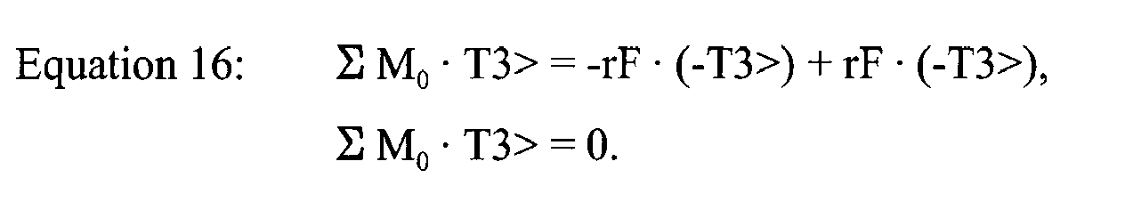
- As shown by Equation 16, if the distances r1, r2 from the rotation point O of a mobile bearing TKA prosthetic 300 are the same to the medial and lateral condyles, the sum of the moments is equal to zero. Thus, the
polyethylene insert 312 does not rotate about the tibial component. An in vivo analysis of the mobile bearingTKA prosthesis 300 evidenced that seven out of nine subjects experienced less than 2.0 degrees of axial rotation. - Referring to
Fig. 4 , a typical fixed bearing TKA prosthetic 400 includes a tibial insert 402 (typically polyethylene) mounted to a tibial implant component (typically a metallic tibial tray, which is not shown). Unlike the mobile bearing posterior stabilisedTKA prosthetic 300 ofFig. 3 , thetibial insert 402 is fixed to the tibial implant component so that the insert does not rotate with respect to the tibial implant component. The forces acting on the fixed bearing posterior stabilisedinsert 402 are similar to those forces defined for the mobile bearing posterior stabilisedTKA prosthetic 300 ofFig. 3 . - Summation of moments acting on the fixed
bearing polyethylene insert 402 can be conducted around the defined point O. The primary difference between the point O ofFig. 4 , and point O ofFig. 3 , is that the chosen point O does not represent a rotation point inFig. 4 , but rather a fixed physical point on thetibial insert 402 in the centre of the post in the T2> direction. Summing the moments around point O is represented byEquation 14, as above. - Similar to the mobile bearing
TKA prosthetic 300 ofFig. 3 , we can assume that the angular acceleration (α) of the femur relative to thetibial insert 402 in the T3> direction is small, and can be set equal to zero. Therefore, with this presumption in place,Equation 14 can be refined into Equation 15, as above. - Where the following information is known, the distance r1 = r2 = r, and the forces FM = FL = F, Equation 15 can be further simplified into Equation 16, as above.
- If the
polyethylene post 404 is located in the centre of thetibial insert 402, in the T1> and T2> directions, then the sum of the moments, in the T3> direction, for the contact forces applied by the femoral component on the tibial insert is equal to zero. Previous in vivo analyses of TKA prosthetics have determined that all TKA prosthetics achieve less axial rotation than a natural knee, while a significant number of TKA recipients are able to achieve less than two degrees of axial rotation of the resulting knee joint and approximately one third of these recipients experience a reverse axial rotation pattern, opposite that of a natural knee. - Referencing
Fig. 5 , a posterior cruciate retaining TKA prosthetic 500 (whether mobile or fixed bearing) allows for posterior cruciate ligament retention, without the presence of a cam/post mechanism 404 found in the posterior stabilisedTKA prosthetic 400 ofFig. 4 . The absence of the cam/post mechanism in a posterior cruciate retaining TKA prosthetic 500 leads to an analysis very similar to those for a posterior stabilised TKA prosthetics discussed above. Since the cam/post mechanism for present day posterior stabilised TKA prosthetics is in the centre of the tibial insert, the cam/post force does not exert a moment. Therefore, when the cam/post mechanism does not induce rotation, the moment analysis for a mobile bearing posterior cruciate TKA prosthetic 500 will be similar to the moment analysis of a mobile bearing posterior stabilised TKA prosthetic 300 (seeFig. 3 ), and the moment analysis for a fixed bearing posterior cruciate retaining TKA prosthetic 500 will be similar to a fixed bearing posterior stabilised TKA prosthetic 400 (seeFig. 4 ), except for the resistive force of the posterior cruciate ligament. In other words, the sum of the moments for the contact forces applied by the femoral component on the tibial insert is equal to zero for these posterior cruciate retainingTKA prosthetics 500. - Referencing
Fig. 6 , a posterior stabilised mobile bearing Moment Induced Total Knee Arthroplasty (MITKA)prosthetic insert 600 is mounted to aprosthetic tibial stem 606, which is preferably implanted into a patient's tibia (not shown). Theinsert 600 includes apost 602 offset in the medial direction from the medial-lateral midline 608 of theinsert 600 providing an axis ofrotation 605 between the insert and a femoral component (not shown), and an axis ofrotation 604 between thetibial stem 606 and theinsert 600 that is shifted in the lateral direction from the medial-lateral midline 608. - Referring to
Fig. 7 , a moment analysis of the MITKAprosthetic insert 600 includes summing the moments, around the point of rotation, O, in the T3> direction. The moment equation is represented by Equation 17:
- Where the following information is known, the distance r1 = 2r, r2 = r3 = r, and the forces FT M = FT L = FT P = F, Equation 17 can be further simplified into Equation 18:

- In this moment summation, the moment induced by the MITKA
prosthetic insert 600 is equal to 2rF, in the clockwise direction (looking down), leading to normal axial rotation of the tibial insert. - Unlike present day mobile bearing posterior stabilised TKA prosthetics 300 (see
Fig. 3 , for example), thetibial insert 600 for the MITKA knee will rotate in the clockwise direction (looking down) as a result of creating a distance between the rotation point O to thepost 602 of the tibial insert 600 (distance represented by r3), increasing the distance from the rotation point O to the medial condyle contact force FT M (distance represented by T1), and decreasing the distance from the rotation point O to the lateral condyle contact force FT L - (distance represented by r2), allowing for the lateral condyle to move more posterior, similar to a natural knee.
- The amount of offset created between the
post 602 and the rotation point O of the MITKAprosthetic insert 600 leads to increased axial rotation of the tibial insert relative to the tibial implant component (not shown) in the clockwise direction (T3> direction). A mathematical model has determined that a 3 mm shift of thepost 602 in the medial direction from the centerline in the medial-lateral direction and a 3 mm shift of the rotation point O in the lateral direction from the centerline in the medial-lateral direction leads to 5 to 13 degrees of normal axial rotation, depending on the weight of the patient, the balancing of the knee, and the amount of force applied by the cam on the post (seeFig. 8 ). A second analysis was conducted using the mathematical model where thepost 602 was shifted 6 mm in the medial direction and the rotation point O was shifted 6 mm in the lateral direction. The results for this analysis revealed the amount of normal axial rotation of the polyethylene increased to a range of 10 to 22 degrees of normal axial rotation, again, depending on the weight of the patient, the balancing of the knee, and the amount of force applied by the cam on the post. A third analysis, where thepost 602 was shifted 10 mm in the medial direction and the rotation point O was shifted 10 mm in the lateral direction lead to normal axial rotation of the polyethylene ranging between 20 to 35 degrees, in the clockwise direction. Greater shifts in the medial and lateral direction are also envisaged, such as, without limitation, 0.01 to 20 millimetres of medial or lateral shift. - Referencing
FIG. 9 , a posterior stabilised fixed bearing Moment Induced Total Knee Arthroplasty (MITKA)prosthetic insert 900 in accordance with the present invention includes a cam/post mechanism 902 shifted in the lateral direction from the medial-later centre 904 of the tibial insert. It is to be understood that the corresponding cam of the femoral component would be likewise shifted in the lateral direction to accommodate the shifted tibial post. - Referring to
FIG. 10 , a moment analysis of the exemplary fixed bearing PS MITKA prosthetic 900 insert includes summing the moments, around point of rotation O, in the T3> direction. The moment equation is represented by Equation 19:
- Where the following information is known, the distance r1 = 2r, r2 = r, and the forces FT M = FT L = F, Equation 19 can be further simplified into Equation 20:

- In this exemplary moment summation, the moment induced by the exemplary MITKA
prosthetic insert 900 is equal to rF, in the clockwise direction (looking down), leading to normal axial rotation of the femur relative to the tibial insert. - The amount of offset created between the
post 902 and the medial-lateral centerline of the MITKAprosthetic insert 900 leads to increased axial rotation of the femoral component relative to the tibial implant component (not shown) in the clockwise direction (T3> direction). An exemplary mathematical model has determined that a 3 mm shift of thepost 902 in the lateral direction from the centerline in the medial-lateral direction leads to a femoral component rotation in the range of 2 to 8 degrees, depending on the weight of the patient, the balancing of the knee, and the amount of force applied by the cam on the post. If thepost 902 is shifted 6 mm in the lateral direction, the amount of femoral component rotation increased to a range of 5 to 13 degrees, and if thepost 902 was shifted 10 mm in the lateral direction, the amount of axial rotation again increased to a range of 9 to 25 degrees. Greater shifts in the medial and lateral direction are also envisaged, such as, without limitation, 0.01 to 20 millimetres of medial or lateral shift. - As discussed previously, the cam/post mechanism can be used in a posterior stabilised TKA prosthetic to generate rotation by creating a moment arm from the rotation point to the post of a mobile bearing TKA, or by shifting the post laterally, increasing the moment arm from the post to the medial condyle shear force. In the posterior cruciate retaining TKA, moments are primarily induced by offsetting the rotation point and building up conformity between the femoral radii and the concave tibial insert radii.
- Referencing
FIG. 11 , a MITKA posterior cruciate retaining (PCR) fixed bearing prosthetic insert 1100 includes amedial receiver 1104 and alateral receiver 1106 that are adapted to receive the medial and lateral condyles, respectively, of a femoral prosthesis (not shown). In order to rotate the tibial insert 1100 clockwise (looking down), the insert 1100 includes greater conformity between the medial condyle and themedial receiver 1104 on the medial side of the tibial insert. In this insert 1100, the radius of themedial receiver 1104 is greater than the radius of the medial condyle, allowing for anterior/posterior translation to occur between the medial condyle and the medial receiver. Increased conformity between themedial receiver 1104 and the medial condyle leads to an increased shear force applied by the medial condyle on the medial receiver of the polyethylene insert, causing a clockwise moment to occur, especially if the superior surface of lateral side of the tibial insert 1100 is either flat or convex in shape, coupled with a flatter shape for the lateral condyle of the femoral prosthesis. - Referencing
FIGS. 12 and13 , a MITKA mobile bearing PCRprosthetic insert 1200 includes the rotation point 1202 (and rotational axis) moved in the lateral direction with respect to thecentre 1204 of the tibial implant baseplate (not shown) using the contours between theinsert 1200 and thefemoral condyles 1206. On the lateral side, the lateralfemoral condyle 1206 is flatter (similar to the shape of a canoe) and thelateral receiver 1208 of the tibial insert is either sloped downward in the anterior-to-posterior direction (seeFIG. 12(b) ) or convex (seeFIG. 12(c) ). On the medial side, the medial femoral condyle includes greater conformity with themedial receiver 1210 on the medial side of thetibial insert 1200. Therefore, as the shear force between the femoral condyles and the tibial insert increases, the amount of shear force will be greater on the medial side and induce a clockwise rotation of the tibial insert due to: (1) the increased conformity; and (2) the moment arm from the rotation point to the medial shear force being greater than the moment arm from the rotation point to the lateral condyle force. - One of the main goals for achieving increased weight-bearing flexion for a total knee arthroplasty is the ability to move the lateral condyle in the posterior direction. In the normal knee, this can be achieved through axial rotation or translation of both condyles. Since, in the normal knee, the medial condyle does not move more than 10 mm in the posterior direction and on average, this amount is less than 5 mm, the lateral condyle achieves posterior contact through femorotibial axial rotation. Moments are introduced in the MITKA so that normal axial rotation could occur and the lateral condyle can achieve greater posterior contact with increasing knee flexion. This inducement of moments is more easily accomplished with a posterior stabilised TKA, where the cam/post force could be used to drive rotation in the clockwise direction or to lever the medial condyle force with respect to the post. In the posterior cruciate ligament retaining TKA, the ability to induce moments is more involved. The MITKA posterior cruciate ligament retaining knee uses increased conformity between the medial condyle and the medial receiver of the polyethylene insert. Also, an increased radius of curvature for the lateral condyle (canoe shaped) allows the lateral condyle contact point to move in the posterior direction within the first 30 degrees of knee flexion. Therefore, the goal of achieve posterior contact with the lateral condyle, with increasing knee flexion can be accomplished in MITKA posterior cruciate ligament retaining TKA through the introduction of moments and by changing the geometrical shapes of the femoral condyles. In this manner, the axis of rotation between the MITKA mobile bearing PCR
prosthetic insert 1200 and the femoral prosthetic can be shifted from the medial-lateral centerline of the insert 1200 (and also from the anterior-posterior centerline), while the axis of rotation between the MITKA mobile bearing PCRprosthetic insert 1200 and the tibial prosthetic tray (not shown) can be shifted from the medial-lateral centerline of the insert 1200 (and also from the anterior-posterior centerline of the insert 1200). - Although the increased conformity between the medial condyle and the receiver in medial aspect of the tibial polyethylene insert and the flatter lateral condyle, contacting either a posterior sloped or convex shaped lateral aspect of the polyethylene insert has been previously described herein for a posterior cruciate retaining TKA, these design features can be used in any TKA prosthetic type. The above mentioned design changes could be used in a PS TKA type to increase axial rotation and could be used in an anterior and posterior cruciate retaining TKA type to ensure normal axial rotation.
- The amount of medial condyle conformity in the prosthetic insert with respect to the medial receiver of the tibial insert may play a significant role. An additional factor that may play a significant role in axial rotation, leading to an increase or decrease in the amount of axial rotation described herein, is condylar balancing at the time of surgery. It is to be understood that the mathematical models referenced in the aforementioned discussion incorporated medial and lateral condyle flexion gaps, during intra-operative ligament balancing, that were equal, leading to the medial condyle contact force being equal to the lateral condyle contact force. If the medial condyle contact force is greater than the lateral condyle contact force, the amount of normal axial rotation would increase over those values predicted by the above- referenced mathematical model, In contrast, if the lateral condyle contact force is greater than the medial condyle contact force, the amount of axial rotation would fall below those values predicted by the model.
- Referencing
FIG. 14 , a MITKA posterior cruciate retaining TKA prosthetic includes increased conformity between the medial condyle and the medial receiver of the tibial (polyethylene) insert in order to induce a clockwise moment of the femur relative to the tibia (normal axial rotation) (seeFIGS. 14(a) & (b) ). Also, the lateral condyle will achieve greater posterior motion due to the flatter condylar geometry (canoe shaped) at full extension leading a rapid change of the contact position from full extension to 30 degrees of knee flexion. This posterior change of the contact position for the lateral condyle may be further assisted by the increased posterior slope of the polyethylene insert (seeFIGS. 14(c) & (d) ) or the convex shape of the polyethylene insert (seeFIGS. 14(e) & (f) ). - Referring to
FIG. 15 , all cam/post mechanisms in present-day TKA prosthetics 1400 include flat surfaces. These flat surfaces lead to the hypothesis that the contact areas would be large, thereby leading to less stress applied by thecam 1402 onto thepost 1404. Unfortunately, if rotation of the femoral component (the cam) 1402 occurs with respect to the tibial insert (the post) 1404 in a fixed bearing posterior stabilised TKA prosthetic, the opposite is true and thecontact area 1406 between the femoral cam and the tibial post becomes very small. A primary concern for decreased contact areas between theflat cam 1402 on aflat post 1404 is edge loading, leading to high stresses that lead to premature tibial insert failure at the post. - Referencing
FIGS. 16 and17 , a MITKA posterior stabilisedTKA prosthetic device 1500 includes atibial insert 1502 with atibial post 1504 having arounded posterior surface 1506. Thisrounded posterior surface 1506 of thepost 1502 is adapted to interact with arounded femoral cam 1508 of afemoral prosthetic component 1510. The radius R for therounded posterior surface 1506 of thepost 1504 and therounded cam 1508 are the similar, but the chosen value of R for the MITKA fixed bearing posterior stabilisedprosthetic device 1500 will depend on the amount of rotation desired. If the MITKA posterior stabilisedprosthetic device 1500 is designed to incorporate minimal femorotibial axial rotation, then the value for R will be higher than the value for R if the MITKA posterior stabilisedprosthetic device 1500 is designed for greater axial rotation.
Claims (5)
- A prosthetic knee joint (1500) comprising:a femoral prosthetic (1510) having a medial condyle and a lateral condyle,a tibial tray prosthetic ,a prosthetic tibial tray insert (900, 1502) which is fixed to the tibial tray prosthetic against rotation relative to the tibial tray prosthetic, the prosthetic tibial tray insert including medial and lateral spaced apart receivers for receiving the condyles of the femoral prosthetic, the prosthetic tibial tray insert also including a stabilizing post (902, 1504) which is configured to engage a cam (1508) on the femoral prosthetic during articulation of the joint, characterised in that the centerline of the stabilizing post is offset laterally from the medial-lateral centerline (904) of the prosthetic tibial tray insert.
- A prosthetic knee joint as claimed in claim 1, in which the conformity of the medial condyle on the femoral prosthetic (1510) with the medial receiver of the tibial tray insert is greater than the conformity of the lateral condyle on the femoral prosthetic with the lateral receiver of the tibial tray insert.
- A prosthetic knee joint as claimed in claim 2, in which the prosthetic tibial tray insert has a (i) lateral condyle receiver having at least one of a convex shape or a sloped from anterior to posterior shape, and (ii) a medial condyle receiver having a concave shape for receiving a convex medial condyle of the femoral prosthesis, the combination of the lateral condyle receiver and the medial condyle receiver creating moments around an axis of rotation to impart horizontal rotation between the prosthetic tibial tray insert and the condyles of the femoral prosthesis.
- A prosthetic knee joint as claimed in claim 1, in which the stabilising post is offset laterally from the medial-lateral centerline of the prosthetic tibial tray insert by a distance of 0.1 to 20 mm.
- A prosthetic knee joint as claimed in claim 1, in which the stabilising post is posteriorly rounded.
Priority Applications (1)
| Application Number | Priority Date | Filing Date | Title |
|---|---|---|---|
| EP12164378.7A EP2478873B1 (en) | 2006-03-21 | 2006-03-21 | Moment induced total arthroplasty prosthetic |
Applications Claiming Priority (3)
| Application Number | Priority Date | Filing Date | Title |
|---|---|---|---|
| EP06739287A EP1996122B1 (en) | 2006-03-21 | 2006-03-21 | Moment induced total arthroplasty prosthetic |
| EP12164378.7A EP2478873B1 (en) | 2006-03-21 | 2006-03-21 | Moment induced total arthroplasty prosthetic |
| PCT/US2006/010431 WO2007108804A1 (en) | 2006-03-21 | 2006-03-21 | Moment induced total arthroplasty prosthetic |
Related Parent Applications (2)
| Application Number | Title | Priority Date | Filing Date |
|---|---|---|---|
| EP06739287A Division EP1996122B1 (en) | 2006-03-21 | 2006-03-21 | Moment induced total arthroplasty prosthetic |
| EP06739287.8 Division | 2006-03-21 |
Publications (2)
| Publication Number | Publication Date |
|---|---|
| EP2478873A1 EP2478873A1 (en) | 2012-07-25 |
| EP2478873B1 true EP2478873B1 (en) | 2014-05-28 |
Family
ID=38522750
Family Applications (3)
| Application Number | Title | Priority Date | Filing Date |
|---|---|---|---|
| EP12164381.1A Active EP2478874B1 (en) | 2006-03-21 | 2006-03-21 | Moment induced total arthroplasty prosthetic |
| EP12164378.7A Active EP2478873B1 (en) | 2006-03-21 | 2006-03-21 | Moment induced total arthroplasty prosthetic |
| EP06739287A Active EP1996122B1 (en) | 2006-03-21 | 2006-03-21 | Moment induced total arthroplasty prosthetic |
Family Applications Before (1)
| Application Number | Title | Priority Date | Filing Date |
|---|---|---|---|
| EP12164381.1A Active EP2478874B1 (en) | 2006-03-21 | 2006-03-21 | Moment induced total arthroplasty prosthetic |
Family Applications After (1)
| Application Number | Title | Priority Date | Filing Date |
|---|---|---|---|
| EP06739287A Active EP1996122B1 (en) | 2006-03-21 | 2006-03-21 | Moment induced total arthroplasty prosthetic |
Country Status (7)
| Country | Link |
|---|---|
| US (5) | US8636807B2 (en) |
| EP (3) | EP2478874B1 (en) |
| JP (1) | JP5101596B2 (en) |
| CN (1) | CN101431967A (en) |
| AU (1) | AU2006340364B2 (en) |
| WO (1) | WO2007108804A1 (en) |
| ZA (1) | ZA200807900B (en) |
Families Citing this family (52)
| Publication number | Priority date | Publication date | Assignee | Title |
|---|---|---|---|---|
| US8066776B2 (en) * | 2001-12-14 | 2011-11-29 | Btg International Limited | Tibial component |
| US6558426B1 (en) | 2000-11-28 | 2003-05-06 | Medidea, Llc | Multiple-cam, posterior-stabilized knee prosthesis |
| US8211181B2 (en) * | 2005-12-14 | 2012-07-03 | New York University | Surface guided knee replacement |
| US8292964B2 (en) * | 2005-12-14 | 2012-10-23 | New York University | Surface guided knee replacement |
| EP2478874B1 (en) | 2006-03-21 | 2014-05-28 | DePuy (Ireland) | Moment induced total arthroplasty prosthetic |
| WO2007114841A1 (en) * | 2006-04-04 | 2007-10-11 | Smith & Nephew, Inc. | Trial coupler systems and methods |
| ES2531704T3 (en) * | 2007-11-02 | 2015-03-18 | Biomet Uk Limited | Prosthetics for simulation of natural kinematics |
| US8292965B2 (en) * | 2008-02-11 | 2012-10-23 | New York University | Knee joint with a ramp |
| WO2009105496A1 (en) * | 2008-02-18 | 2009-08-27 | Maxx Orthopedics, Inc. | Total knee replacement prosthesis |
| AU2009271389B2 (en) | 2008-06-24 | 2013-01-31 | Peter Stanley Walker | Recess-ramp knee joint prosthesis |
| US8206451B2 (en) | 2008-06-30 | 2012-06-26 | Depuy Products, Inc. | Posterior stabilized orthopaedic prosthesis |
| US8236061B2 (en) | 2008-06-30 | 2012-08-07 | Depuy Products, Inc. | Orthopaedic knee prosthesis having controlled condylar curvature |
| US8828086B2 (en) | 2008-06-30 | 2014-09-09 | Depuy (Ireland) | Orthopaedic femoral component having controlled condylar curvature |
| US8187335B2 (en) | 2008-06-30 | 2012-05-29 | Depuy Products, Inc. | Posterior stabilized orthopaedic knee prosthesis having controlled condylar curvature |
| US9119723B2 (en) | 2008-06-30 | 2015-09-01 | Depuy (Ireland) | Posterior stabilized orthopaedic prosthesis assembly |
| US8192498B2 (en) | 2008-06-30 | 2012-06-05 | Depuy Products, Inc. | Posterior cructiate-retaining orthopaedic knee prosthesis having controlled condylar curvature |
| US9168145B2 (en) | 2008-06-30 | 2015-10-27 | Depuy (Ireland) | Posterior stabilized orthopaedic knee prosthesis having controlled condylar curvature |
| US8202323B2 (en) * | 2008-07-16 | 2012-06-19 | Depuy Products, Inc. | Knee prostheses with enhanced kinematics |
| US7981159B2 (en) * | 2008-07-16 | 2011-07-19 | Depuy Products, Inc. | Antero-posterior placement of axis of rotation for a rotating platform |
| US8915965B2 (en) | 2009-05-07 | 2014-12-23 | Depuy (Ireland) | Anterior stabilized knee implant |
| WO2011016905A1 (en) * | 2009-07-27 | 2011-02-10 | Thomas P Andriacchi | Knee replacement system and method for enabling natural knee movement |
| US8998997B2 (en) | 2009-08-11 | 2015-04-07 | Michael D. Ries | Implantable mobile bearing prosthetics |
| US9095453B2 (en) * | 2009-08-11 | 2015-08-04 | Michael D. Ries | Position adjustable trial systems for prosthetic implants |
| US8382848B2 (en) * | 2009-08-11 | 2013-02-26 | Imds Corporation | Position adjustable trial systems for prosthetic implants |
| US8906105B2 (en) | 2009-08-11 | 2014-12-09 | Michael D. Ries | Systems and methods for mobile bearing prosthetic knee |
| US8568485B2 (en) * | 2009-08-11 | 2013-10-29 | Imds Corporation | Articulating trials for prosthetic implants |
| US8496666B2 (en) | 2009-08-11 | 2013-07-30 | Imds Corporation | Instrumentation for mobile bearing prosthetics |
| CN101697931B (en) * | 2009-09-30 | 2011-09-28 | 北京纳通投资有限公司 | Liner part knee-joint prosthesis, tibia part and knee-joint prosthesis |
| CN102821717B (en) * | 2010-01-29 | 2016-01-20 | 史密夫和内修有限公司 | Cross maintenance knee prostheses |
| WO2012012726A1 (en) | 2010-07-23 | 2012-01-26 | Medicinelodge, Inc Dba Imds Co-Innovation | Systems and methods for prosthetic knee |
| ES2632995T3 (en) | 2010-07-24 | 2017-09-18 | Zimmer, Inc. | Asymmetric tibia components for a knee prosthesis |
| US8764840B2 (en) | 2010-07-24 | 2014-07-01 | Zimmer, Inc. | Tibial prosthesis |
| EP2613739B1 (en) | 2010-09-10 | 2017-06-07 | Zimmer, Inc. | Motion facilitating tibial components for a knee prosthesis |
| US8603101B2 (en) | 2010-12-17 | 2013-12-10 | Zimmer, Inc. | Provisional tibial prosthesis system |
| CH704563B1 (en) * | 2011-02-21 | 2015-04-30 | Microport Orthopedics Inc | Patient Specific Proberepositionsblock. |
| CA2841538A1 (en) * | 2011-07-13 | 2013-01-17 | The General Hospital Corporation D/B/A Massachusetts General Hospital | Methods and devices for knee joint replacement with anterior cruciate ligament substitution |
| EP3848005A3 (en) | 2011-11-18 | 2021-09-15 | Zimmer, Inc. | Tibial bearing component for a knee prosthesis with improved articular characteristics |
| WO2013077919A1 (en) | 2011-11-21 | 2013-05-30 | Zimmer, Inc. | Tibial baseplate with asymmetric placement of fixation structures |
| AU2015201511B2 (en) * | 2011-11-21 | 2016-07-21 | Zimmer, Inc. | Tibial baseplate with asymmetric placement of fixation structures |
| EP2809273B1 (en) | 2012-01-30 | 2021-05-05 | Zimmer, Inc. | Asymmetric tibial components for a knee prosthesis |
| US9925052B2 (en) | 2013-08-30 | 2018-03-27 | Zimmer, Inc. | Method for optimizing implant designs |
| AU2015229377B2 (en) * | 2014-03-12 | 2019-09-19 | Exactech, Inc. | Prosthesis component with offset adjustability |
| CN108135701B (en) | 2015-09-21 | 2019-12-24 | 捷迈有限公司 | Prosthesis system including tibial bearing component |
| US10179052B2 (en) | 2016-07-28 | 2019-01-15 | Depuy Ireland Unlimited Company | Total knee implant prosthesis assembly and method |
| EP3592299B1 (en) | 2017-03-10 | 2021-06-09 | Zimmer, Inc. | Tibial prosthesis with tibial bearing component securing feature |
| CA3063415C (en) | 2017-05-12 | 2021-10-19 | Zimmer, Inc. | Femoral prostheses with upsizing and downsizing capabilities |
| IT201700091423A1 (en) * | 2017-08-07 | 2019-02-07 | Rejoint S R L | PROSTHESIS FOR A KNEE AND METHOD FOR ITS REALIZATION |
| US11426282B2 (en) | 2017-11-16 | 2022-08-30 | Zimmer, Inc. | Implants for adding joint inclination to a knee arthroplasty |
| JP6482637B2 (en) * | 2017-12-11 | 2019-03-13 | 京セラ株式会社 | Total knee implant |
| US10835380B2 (en) | 2018-04-30 | 2020-11-17 | Zimmer, Inc. | Posterior stabilized prosthesis system |
| EP3698761B1 (en) | 2019-02-22 | 2021-11-17 | Stryker European Operations Limited | Total ankle prosthesis |
| WO2023081319A1 (en) * | 2021-11-03 | 2023-05-11 | Actuos, LLC | Unicompartmental knee arthroplasty systems and methods |
Citations (2)
| Publication number | Priority date | Publication date | Assignee | Title |
|---|---|---|---|---|
| FR2787012A1 (en) * | 1998-12-11 | 2000-06-16 | Bex Anne Marie | Knee joint endoprosthesis has two cylinders projecting from underside of tibial component for partial or complete joint replacement |
| WO2005037147A1 (en) * | 2003-10-17 | 2005-04-28 | Smith & Nephew, Inc. | High flexion articular insert |
Family Cites Families (114)
| Publication number | Priority date | Publication date | Assignee | Title |
|---|---|---|---|---|
| US3765033A (en) * | 1971-01-19 | 1973-10-16 | D Goldberg | Prosthetic knee joint assembly with mutually slidable and rollable joint sections |
| GB1448818A (en) | 1972-09-18 | 1976-09-08 | Nat Res Dev | Prosthetic knee joint devices |
| US3869731A (en) | 1973-02-14 | 1975-03-11 | Univ California | Articulated two-part prosthesis replacing the knee joint |
| US4209861A (en) | 1978-02-22 | 1980-07-01 | Howmedica, Inc. | Joint prosthesis |
| US4470158A (en) | 1978-03-10 | 1984-09-11 | Biomedical Engineering Corp. | Joint endoprosthesis |
| CH632151A5 (en) | 1978-10-06 | 1982-09-30 | Sulzer Ag | ENDOPROTHESIS FOR A KNEE JOINT. |
| US4215439A (en) * | 1978-10-16 | 1980-08-05 | Zimmer, USA | Semi-restraining knee prosthesis |
| US4340978A (en) * | 1979-07-02 | 1982-07-27 | Biomedical Engineering Corp. | New Jersey meniscal bearing knee replacement |
| US4262368A (en) * | 1979-09-24 | 1981-04-21 | Wright Manufacturing Company | Rotating and hinged knee prosthesis |
| FR2621243A1 (en) | 1987-10-06 | 1989-04-07 | Cuilleron J | Total knee prothesis |
| US4888021A (en) | 1988-02-02 | 1989-12-19 | Joint Medical Products Corporation | Knee and patellar prosthesis |
| US5007933A (en) | 1989-01-31 | 1991-04-16 | Osteonics Corp. | Modular knee prosthesis system |
| US5147405A (en) | 1990-02-07 | 1992-09-15 | Boehringer Mannheim Corporation | Knee prosthesis |
| US5116375A (en) | 1990-08-27 | 1992-05-26 | Hofmann Aaron A | Knee prosthesis |
| US5071438A (en) * | 1990-11-07 | 1991-12-10 | Intermedics Orthopedics, Inc. | Tibial prothesis with pivoting articulating surface |
| AU9089891A (en) * | 1990-11-14 | 1992-06-11 | Arch Development Corporation | Improved floating bearing prosthetic knee |
| GB9102348D0 (en) | 1991-02-04 | 1991-03-20 | Inst Of Orthopaedics The | Prosthesis for knee replacement |
| US5609639A (en) * | 1991-02-04 | 1997-03-11 | Walker; Peter S. | Prosthesis for knee replacement |
| GB9102633D0 (en) * | 1991-02-07 | 1991-03-27 | Finsbury Instr Ltd | Knee prosthesis |
| US5358527A (en) * | 1991-03-22 | 1994-10-25 | Forte Mark R | Total knee prosthesis with resurfacing and posterior stabilization capability |
| US5395401A (en) * | 1991-06-17 | 1995-03-07 | Bahler; Andre | Prosthetic device for a complex joint |
| US5133758A (en) | 1991-09-16 | 1992-07-28 | Research And Education Institute, Inc. Harbor-Ucla Medical Center | Total knee endoprosthesis with fixed flexion-extension axis of rotation |
| US5330534A (en) | 1992-02-10 | 1994-07-19 | Biomet, Inc. | Knee joint prosthesis with interchangeable components |
| NZ243181A (en) | 1992-04-23 | 1994-10-26 | Michael John Pappas | Prosthetic joint with guide means to limit articulation of a first element and bearing means to two degrees of freedom |
| US5824102A (en) * | 1992-06-19 | 1998-10-20 | Buscayret; Christian | Total knee prosthesis |
| US5344460A (en) | 1992-10-30 | 1994-09-06 | Encore Orthopedics, Inc. | Prosthesis system |
| US5658342A (en) * | 1992-11-16 | 1997-08-19 | Arch Development | Stabilized prosthetic knee |
| US5413604A (en) * | 1992-12-24 | 1995-05-09 | Osteonics Corp. | Prosthetic knee implant for an anterior cruciate ligament deficient total knee replacement |
| US5370699A (en) | 1993-01-21 | 1994-12-06 | Orthomet, Inc. | Modular knee joint prosthesis |
| US5405396A (en) | 1993-07-01 | 1995-04-11 | Zimmer, Inc. | Tibial prosthesis |
| GB9314832D0 (en) | 1993-07-16 | 1993-09-01 | Walker Peter S | Prostheses for knee replacement |
| EP0648817B1 (en) * | 1993-10-13 | 1999-11-10 | Ciba SC Holding AG | Novel fluorescent dyes |
| US5549686A (en) * | 1994-06-06 | 1996-08-27 | Zimmer, Inc. | Knee prosthesis having a tapered cam |
| SE504971C2 (en) * | 1994-07-11 | 1997-06-02 | Sandvik Ab | Saw blade with fluid injection |
| GB9415180D0 (en) | 1994-07-28 | 1994-09-21 | Walker Peter S | Stabilised mobile bearing knee |
| US7494507B2 (en) * | 2000-01-30 | 2009-02-24 | Diamicron, Inc. | Articulating diamond-surfaced spinal implants |
| US5571194A (en) * | 1994-11-14 | 1996-11-05 | Johnson & Johnson Professional, Inc. | Femoral augmentation system for artificial knee joint |
| US5702458A (en) | 1994-12-09 | 1997-12-30 | New York Society For The Ruptured And Crippled Maintaining The Hospital For Special Surgery | Joint prosthesis |
| AUPN089495A0 (en) | 1995-02-03 | 1995-03-02 | Denupo Pty. Ltd. | Knee prosthesis |
| US5639279A (en) * | 1995-02-09 | 1997-06-17 | Intermedics Orthopedics, Inc. | Posteriorly-stabilized prosthetic knee |
| US5609643A (en) | 1995-03-13 | 1997-03-11 | Johnson & Johnson Professional, Inc. | Knee joint prosthesis |
| US5683468A (en) | 1995-03-13 | 1997-11-04 | Pappas; Michael J. | Mobile bearing total joint replacement |
| DE19529824A1 (en) * | 1995-08-14 | 1997-02-20 | Bodo Gnutzmann | Bi-condylar endoprosthesis for knee |
| US5871546A (en) * | 1995-09-29 | 1999-02-16 | Johnson & Johnson Professional, Inc. | Femoral component condyle design for knee prosthesis |
| US5776201A (en) * | 1995-10-02 | 1998-07-07 | Johnson & Johnson Professional, Inc. | Modular femoral trial system |
| US5681354A (en) | 1996-02-20 | 1997-10-28 | Board Of Regents, University Of Colorado | Asymmetrical femoral component for knee prosthesis |
| US5871543A (en) * | 1996-02-23 | 1999-02-16 | Hofmann; Aaron A. | Tibial prosthesis with mobile bearing member |
| HU219444B (en) | 1996-02-26 | 2001-04-28 | Gábor Krakovits | Sliding surface for knee-joint prothesis |
| GB9609609D0 (en) | 1996-05-08 | 1996-07-10 | Midland International Orthopae | Knee prosthesis |
| US5964808A (en) * | 1996-07-11 | 1999-10-12 | Wright Medical Technology, Inc. | Knee prosthesis |
| US6004351A (en) | 1996-09-14 | 1999-12-21 | Mizuho Ika Kogyo Kabushiki Kaisha | Prosthetic knee joint |
| US5824100A (en) | 1996-10-30 | 1998-10-20 | Osteonics Corp. | Knee prosthesis with increased balance and reduced bearing stress |
| GB2336317B (en) | 1996-12-09 | 2001-02-14 | Jacques Afriat | Complete knee joint prosthesis |
| GB9707717D0 (en) | 1997-04-16 | 1997-06-04 | Walker Peter S | Knee prosthesis having guide surfaces for control of anterior-posterior translation |
| DE69725291T2 (en) * | 1997-07-10 | 2004-07-29 | Société Ortho-Id | knee prosthesis |
| US6039764A (en) | 1997-08-18 | 2000-03-21 | Arch Development Corporation | Prosthetic knee with adjusted center of internal/external rotation |
| FR2768613B1 (en) * | 1997-09-23 | 1999-12-17 | Tornier Sa | KNEE PROSTHESIS WITH ROTATABLE PLATFORM |
| US6206926B1 (en) * | 1997-10-06 | 2001-03-27 | Biomedical Engineering Trust I | Prosthetic knee joint with enhanced posterior stabilization and dislocation prevention features |
| US6325828B1 (en) * | 1997-12-02 | 2001-12-04 | Rose Biomedical Research | Apparatus for knee prosthesis |
| FR2772259B1 (en) * | 1997-12-12 | 2000-03-03 | Tornier Sa | IMPROVEMENTS IN TOTAL KNEE PROSTHESES COMPRISING A FEMORAL ELEMENT AND A TIBIAL PLATE |
| US6123729A (en) | 1998-03-10 | 2000-09-26 | Bristol-Myers Squibb Company | Four compartment knee |
| US6080195A (en) | 1998-07-08 | 2000-06-27 | Johnson & Johnson Professional, Inc. | Rotatable and translatable joint prosthesis with posterior stabilization |
| US6443991B1 (en) | 1998-09-21 | 2002-09-03 | Depuy Orthopaedics, Inc. | Posterior stabilized mobile bearing knee |
| US6500208B1 (en) * | 1998-10-16 | 2002-12-31 | Biomet, Inc. | Nonmodular joint prosthesis convertible in vivo to a modular prosthesis |
| US6972039B2 (en) | 1999-03-01 | 2005-12-06 | Biomet, Inc. | Floating bearing knee joint prosthesis with a fixed tibial post |
| FR2791553B1 (en) | 1999-04-01 | 2001-07-06 | Merck Biomaterial France | ANTERO-POSTERO-STABILIZED KNEE PROSTHESIS |
| FR2796836B1 (en) * | 1999-07-26 | 2002-03-22 | Michel Bercovy | NEW KNEE PROSTHESIS |
| US6379388B1 (en) * | 1999-12-08 | 2002-04-30 | Ortho Development Corporation | Tibial prosthesis locking system and method of repairing knee joint |
| FR2805455B1 (en) | 2000-02-24 | 2002-04-19 | Aesculap Sa | FEMORAL COMPONENT OF A THREE-BEND KNEE PROSTHESIS |
| US6491726B2 (en) * | 2000-03-08 | 2002-12-10 | Biomedical Engineering Trust I | Posterior stabilized prosthetic knee replacement with bearing translation and dislocation prevention features |
| US6475241B2 (en) * | 2000-03-13 | 2002-11-05 | Biomedical Engineering Trust I | Posterior stabilized knee replacement with bearing translation for knees with retained collateral ligaments |
| FR2812540B1 (en) | 2000-08-01 | 2002-10-31 | Jean Manuel Aubaniac | TWO-COMPARTMENTAL KNEE PROSTHESIS |
| US6558426B1 (en) * | 2000-11-28 | 2003-05-06 | Medidea, Llc | Multiple-cam, posterior-stabilized knee prosthesis |
| US20020120340A1 (en) * | 2001-02-23 | 2002-08-29 | Metzger Robert G. | Knee joint prosthesis |
| US6797005B2 (en) * | 2001-02-28 | 2004-09-28 | Biomedical Engineering Trust | Deep flexion posterior stabilized knee replacement with bearing translation |
| JP4476548B2 (en) | 2001-04-17 | 2010-06-09 | イグザクテック・インコーポレイテッド | Artificial knee joint |
| US6589283B1 (en) * | 2001-05-15 | 2003-07-08 | Biomet, Inc. | Elongated femoral component |
| US6569096B2 (en) | 2001-06-06 | 2003-05-27 | International Business Machines Corporation | System and method of automating multidimensional scaling for psychophysics |
| JP2005514157A (en) * | 2001-12-21 | 2005-05-19 | スミス アンド ネフュー インコーポレーテッド | Hinged joint system |
| US6669618B2 (en) * | 2001-12-21 | 2003-12-30 | The Procter & Gamble Company | Method of dynamically pre-fastening a disposable absorbent article having a slot-and-tab fastening system |
| FR2835178B1 (en) | 2002-01-31 | 2004-12-03 | Jacques Marie Rousseau | TIBIAL PROSTHETIC ASSEMBLY FOR SLIDING KNEE PROSTHESIS |
| FR2835738B1 (en) | 2002-02-14 | 2004-10-01 | Jacques Afriat | TOTAL KNEE PROSTHESIS |
| GB0204381D0 (en) * | 2002-02-26 | 2002-04-10 | Mcminn Derek J W | Knee prosthesis |
| DE10220591B4 (en) | 2002-05-08 | 2004-03-18 | Mathys Medizinaltechnik Ag | Joint prosthesis with an intermediate element with different radii of curvature |
| US20040002767A1 (en) * | 2002-06-28 | 2004-01-01 | Joseph Wyss | Modular knee joint prosthesis |
| US6770099B2 (en) * | 2002-11-19 | 2004-08-03 | Zimmer Technology, Inc. | Femoral prosthesis |
| ES2363767T3 (en) | 2002-12-20 | 2011-08-16 | SMITH & NEPHEW, INC. | HIGH PERFORMANCE KNEE PROSTHESIS. |
| US7160330B2 (en) * | 2003-01-21 | 2007-01-09 | Howmedica Osteonics Corp. | Emulating natural knee kinematics in a knee prosthesis |
| JP4509998B2 (en) | 2003-02-08 | 2010-07-21 | デピュー インターナショナル リミテッド | Knee joint prosthesis |
| US6986791B1 (en) * | 2003-04-15 | 2006-01-17 | Biomet Manufacturing Corp. | Knee prosthesis with moveable post |
| FR2854060B1 (en) | 2003-04-24 | 2006-02-24 | Aesculap Sa | POSTERO-STABILIZED PROSTHESIS WITH TIBIAL ANTI-TILING PLOT |
| FR2854792B1 (en) * | 2003-05-12 | 2005-09-09 | Tornier Sa | GAME OF PROTHETIC ELEMENTS FOR A TIBIAL PROTHETIC SET |
| US7081137B1 (en) | 2003-06-23 | 2006-07-25 | Howmedica Osteonics Corp. | Knee prosthesis with extended range of motion |
| DE602004026190D1 (en) * | 2003-07-17 | 2010-05-06 | Exactech Inc | MOVABLE LOADABLE KNEE PROSTHESIS |
| US7261740B2 (en) * | 2003-10-29 | 2007-08-28 | Wright Medical Technology, Inc. | Tibial knee prosthesis |
| US20090210066A1 (en) | 2004-01-23 | 2009-08-20 | The General Hospital Corporation Dba Massachusetts General Hospital | Anterior cruciate ligament substituting knee replacement prosthesis |
| DE202004003133U1 (en) * | 2004-02-26 | 2004-07-29 | Aap Implantate Ag | Joint replacement tibial plateau |
| EP1574185B1 (en) * | 2004-03-09 | 2012-05-23 | Zimmer Technology, Inc. | Tibial knee component with a mobile bearing |
| WO2005087125A2 (en) * | 2004-03-10 | 2005-09-22 | Depuy International Ltd | Orthopaedic operating systems, methods, implants and instruments |
| JP3915989B2 (en) | 2004-03-17 | 2007-05-16 | 徹 勝呂 | Artificial knee joint |
| US20060178749A1 (en) * | 2005-02-10 | 2006-08-10 | Zimmer Technology, Inc. | Modular porous implant |
| WO2007052297A2 (en) | 2005-08-24 | 2007-05-10 | Kantilal Hastimal Sancheti | Knee joint prosthesis |
| US8211181B2 (en) | 2005-12-14 | 2012-07-03 | New York University | Surface guided knee replacement |
| EP1993483B1 (en) * | 2006-03-13 | 2013-06-19 | Mako Surgical Corp. | Prosthetic device and method for planning the implantation |
| EP2478874B1 (en) | 2006-03-21 | 2014-05-28 | DePuy (Ireland) | Moment induced total arthroplasty prosthetic |
| GB0607544D0 (en) | 2006-04-13 | 2006-05-24 | Pinskerova Vera | Knee prothesis |
| US7658767B2 (en) | 2006-06-30 | 2010-02-09 | Depuy Products, Inc. | Hinged orthopaedic prosthesis |
| US7842093B2 (en) * | 2006-07-18 | 2010-11-30 | Biomet Manufacturing Corp. | Method and apparatus for a knee implant |
| US7875081B2 (en) * | 2006-09-25 | 2011-01-25 | New York Society For The Ruptured And Crippled Maintaining The Hospital For Special Surgery | Posterior stabilized knee prosthesis |
| AU2009271389B2 (en) * | 2008-06-24 | 2013-01-31 | Peter Stanley Walker | Recess-ramp knee joint prosthesis |
| US8075626B2 (en) | 2008-06-30 | 2011-12-13 | Depuy Products, Inc. | Orthopaedic knee prosthesis having increased axial-rotation |
| US8236061B2 (en) * | 2008-06-30 | 2012-08-07 | Depuy Products, Inc. | Orthopaedic knee prosthesis having controlled condylar curvature |
| US8715358B2 (en) | 2008-07-18 | 2014-05-06 | Michael A. Masini | PCL retaining ACL substituting TKA apparatus and method |
| US8915965B2 (en) | 2009-05-07 | 2014-12-23 | Depuy (Ireland) | Anterior stabilized knee implant |
-
2006
- 2006-03-21 EP EP12164381.1A patent/EP2478874B1/en active Active
- 2006-03-21 JP JP2009501393A patent/JP5101596B2/en active Active
- 2006-03-21 EP EP12164378.7A patent/EP2478873B1/en active Active
- 2006-03-21 CN CNA2006800544752A patent/CN101431967A/en active Pending
- 2006-03-21 EP EP06739287A patent/EP1996122B1/en active Active
- 2006-03-21 AU AU2006340364A patent/AU2006340364B2/en active Active
- 2006-03-21 WO PCT/US2006/010431 patent/WO2007108804A1/en active Application Filing
-
2008
- 2008-09-04 US US12/203,987 patent/US8636807B2/en active Active
- 2008-09-15 ZA ZA2008/07900A patent/ZA200807900B/en unknown
-
2013
- 2013-12-18 US US14/132,343 patent/US9254197B2/en active Active
-
2015
- 2015-12-09 US US14/963,293 patent/US10045849B2/en active Active
-
2018
- 2018-07-16 US US16/036,148 patent/US10932915B2/en active Active
-
2021
- 2021-01-22 US US17/155,130 patent/US20210137689A1/en not_active Abandoned
Patent Citations (2)
| Publication number | Priority date | Publication date | Assignee | Title |
|---|---|---|---|---|
| FR2787012A1 (en) * | 1998-12-11 | 2000-06-16 | Bex Anne Marie | Knee joint endoprosthesis has two cylinders projecting from underside of tibial component for partial or complete joint replacement |
| WO2005037147A1 (en) * | 2003-10-17 | 2005-04-28 | Smith & Nephew, Inc. | High flexion articular insert |
Also Published As
| Publication number | Publication date |
|---|---|
| EP2478873A1 (en) | 2012-07-25 |
| US8636807B2 (en) | 2014-01-28 |
| US20140107793A1 (en) | 2014-04-17 |
| US20180318094A1 (en) | 2018-11-08 |
| EP2478874B1 (en) | 2014-05-28 |
| US9254197B2 (en) | 2016-02-09 |
| WO2007108804A1 (en) | 2007-09-27 |
| WO2007108804A8 (en) | 2008-11-06 |
| US20160089244A1 (en) | 2016-03-31 |
| US10932915B2 (en) | 2021-03-02 |
| US20210137689A1 (en) | 2021-05-13 |
| JP5101596B2 (en) | 2012-12-19 |
| EP1996122A4 (en) | 2010-04-14 |
| CN101431967A (en) | 2009-05-13 |
| EP1996122A1 (en) | 2008-12-03 |
| EP1996122B1 (en) | 2012-11-21 |
| AU2006340364B2 (en) | 2011-04-28 |
| US10045849B2 (en) | 2018-08-14 |
| AU2006340364A1 (en) | 2007-09-27 |
| JP2009530020A (en) | 2009-08-27 |
| US20090043396A1 (en) | 2009-02-12 |
| ZA200807900B (en) | 2011-05-25 |
| EP2478874A1 (en) | 2012-07-25 |
Similar Documents
| Publication | Publication Date | Title |
|---|---|---|
| EP2478873B1 (en) | Moment induced total arthroplasty prosthetic | |
| EP2145606B1 (en) | Knee prosthesis | |
| EP2275053B1 (en) | Orthopaedic knee prosthesis | |
| EP2450009B1 (en) | Femoral component of a knee joint prosthesis | |
| Banks et al. | In vivo kinematics of cruciate-retaining and-substituting knee arthroplasties | |
| EP2886086B1 (en) | Posterior stabilized orthopaedic knee prosthesis | |
| US4151615A (en) | Prosthetic patello-femoral joint | |
| EP2726020B1 (en) | Posterior stabilized orthopaedic knee prosthesis having controlled condylar curvature | |
| Sledge et al. | Total knee arthroplasty in rheumatoid arthritis | |
| AU2014262276B2 (en) | Moment induced total arthroplasty prosthetic | |
| Andriacchi et al. | Gait analysis and total knee replacement | |
| van Arkel et al. | (i) Basics of orthopaedic biomechanics | |
| Zambianchi et al. | The Kinematics of the Three Compartments of the Native and Partially Implanted Knee | |
| CN104207863A (en) | Moment-introduced whole-joint replacing prosthesis |
Legal Events
| Date | Code | Title | Description |
|---|---|---|---|
| PUAI | Public reference made under article 153(3) epc to a published international application that has entered the european phase |
Free format text: ORIGINAL CODE: 0009012 |
|
| AC | Divisional application: reference to earlier application |
Ref document number: 1996122 Country of ref document: EP Kind code of ref document: P |
|
| AK | Designated contracting states |
Kind code of ref document: A1 Designated state(s): AT BE BG CH CY CZ DE DK EE ES FI FR GB GR HU IE IS IT LI LT LU LV MC NL PL PT RO SE SI SK TR |
|
| 17P | Request for examination filed |
Effective date: 20130122 |
|
| 17Q | First examination report despatched |
Effective date: 20130306 |
|
| GRAP | Despatch of communication of intention to grant a patent |
Free format text: ORIGINAL CODE: EPIDOSNIGR1 |
|
| INTG | Intention to grant announced |
Effective date: 20140313 |
|
| GRAS | Grant fee paid |
Free format text: ORIGINAL CODE: EPIDOSNIGR3 |
|
| GRAA | (expected) grant |
Free format text: ORIGINAL CODE: 0009210 |
|
| AC | Divisional application: reference to earlier application |
Ref document number: 1996122 Country of ref document: EP Kind code of ref document: P |
|
| AK | Designated contracting states |
Kind code of ref document: B1 Designated state(s): AT BE BG CH CY CZ DE DK EE ES FI FR GB GR HU IE IS IT LI LT LU LV MC NL PL PT RO SE SI SK TR |
|
| REG | Reference to a national code |
Ref country code: GB Ref legal event code: FG4D |
|
| REG | Reference to a national code |
Ref country code: CH Ref legal event code: NV Representative=s name: E. BLUM AND CO. AG PATENT- UND MARKENANWAELTE , CH Ref country code: CH Ref legal event code: EP |
|
| REG | Reference to a national code |
Ref country code: AT Ref legal event code: REF Ref document number: 670179 Country of ref document: AT Kind code of ref document: T Effective date: 20140615 |
|
| REG | Reference to a national code |
Ref country code: IE Ref legal event code: FG4D |
|
| REG | Reference to a national code |
Ref country code: DE Ref legal event code: R096 Ref document number: 602006041758 Country of ref document: DE Effective date: 20140710 |
|
| REG | Reference to a national code |
Ref country code: AT Ref legal event code: MK05 Ref document number: 670179 Country of ref document: AT Kind code of ref document: T Effective date: 20140528 |
|
| REG | Reference to a national code |
Ref country code: NL Ref legal event code: VDEP Effective date: 20140528 |
|
| REG | Reference to a national code |
Ref country code: LT Ref legal event code: MG4D |
|
| PG25 | Lapsed in a contracting state [announced via postgrant information from national office to epo] |
Ref country code: GR Free format text: LAPSE BECAUSE OF FAILURE TO SUBMIT A TRANSLATION OF THE DESCRIPTION OR TO PAY THE FEE WITHIN THE PRESCRIBED TIME-LIMIT Effective date: 20140829 Ref country code: CY Free format text: LAPSE BECAUSE OF FAILURE TO SUBMIT A TRANSLATION OF THE DESCRIPTION OR TO PAY THE FEE WITHIN THE PRESCRIBED TIME-LIMIT Effective date: 20140528 Ref country code: FI Free format text: LAPSE BECAUSE OF FAILURE TO SUBMIT A TRANSLATION OF THE DESCRIPTION OR TO PAY THE FEE WITHIN THE PRESCRIBED TIME-LIMIT Effective date: 20140528 Ref country code: LT Free format text: LAPSE BECAUSE OF FAILURE TO SUBMIT A TRANSLATION OF THE DESCRIPTION OR TO PAY THE FEE WITHIN THE PRESCRIBED TIME-LIMIT Effective date: 20140528 |
|
| PG25 | Lapsed in a contracting state [announced via postgrant information from national office to epo] |
Ref country code: AT Free format text: LAPSE BECAUSE OF FAILURE TO SUBMIT A TRANSLATION OF THE DESCRIPTION OR TO PAY THE FEE WITHIN THE PRESCRIBED TIME-LIMIT Effective date: 20140528 Ref country code: LV Free format text: LAPSE BECAUSE OF FAILURE TO SUBMIT A TRANSLATION OF THE DESCRIPTION OR TO PAY THE FEE WITHIN THE PRESCRIBED TIME-LIMIT Effective date: 20140528 Ref country code: SE Free format text: LAPSE BECAUSE OF FAILURE TO SUBMIT A TRANSLATION OF THE DESCRIPTION OR TO PAY THE FEE WITHIN THE PRESCRIBED TIME-LIMIT Effective date: 20140528 |
|
| PG25 | Lapsed in a contracting state [announced via postgrant information from national office to epo] |
Ref country code: PT Free format text: LAPSE BECAUSE OF FAILURE TO SUBMIT A TRANSLATION OF THE DESCRIPTION OR TO PAY THE FEE WITHIN THE PRESCRIBED TIME-LIMIT Effective date: 20140929 |
|
| PG25 | Lapsed in a contracting state [announced via postgrant information from national office to epo] |
Ref country code: BE Free format text: LAPSE BECAUSE OF FAILURE TO SUBMIT A TRANSLATION OF THE DESCRIPTION OR TO PAY THE FEE WITHIN THE PRESCRIBED TIME-LIMIT Effective date: 20140528 Ref country code: SK Free format text: LAPSE BECAUSE OF FAILURE TO SUBMIT A TRANSLATION OF THE DESCRIPTION OR TO PAY THE FEE WITHIN THE PRESCRIBED TIME-LIMIT Effective date: 20140528 Ref country code: DK Free format text: LAPSE BECAUSE OF FAILURE TO SUBMIT A TRANSLATION OF THE DESCRIPTION OR TO PAY THE FEE WITHIN THE PRESCRIBED TIME-LIMIT Effective date: 20140528 Ref country code: RO Free format text: LAPSE BECAUSE OF FAILURE TO SUBMIT A TRANSLATION OF THE DESCRIPTION OR TO PAY THE FEE WITHIN THE PRESCRIBED TIME-LIMIT Effective date: 20140528 Ref country code: EE Free format text: LAPSE BECAUSE OF FAILURE TO SUBMIT A TRANSLATION OF THE DESCRIPTION OR TO PAY THE FEE WITHIN THE PRESCRIBED TIME-LIMIT Effective date: 20140528 Ref country code: CZ Free format text: LAPSE BECAUSE OF FAILURE TO SUBMIT A TRANSLATION OF THE DESCRIPTION OR TO PAY THE FEE WITHIN THE PRESCRIBED TIME-LIMIT Effective date: 20140528 Ref country code: ES Free format text: LAPSE BECAUSE OF FAILURE TO SUBMIT A TRANSLATION OF THE DESCRIPTION OR TO PAY THE FEE WITHIN THE PRESCRIBED TIME-LIMIT Effective date: 20140528 |
|
| PG25 | Lapsed in a contracting state [announced via postgrant information from national office to epo] |
Ref country code: NL Free format text: LAPSE BECAUSE OF FAILURE TO SUBMIT A TRANSLATION OF THE DESCRIPTION OR TO PAY THE FEE WITHIN THE PRESCRIBED TIME-LIMIT Effective date: 20140528 Ref country code: PL Free format text: LAPSE BECAUSE OF FAILURE TO SUBMIT A TRANSLATION OF THE DESCRIPTION OR TO PAY THE FEE WITHIN THE PRESCRIBED TIME-LIMIT Effective date: 20140528 |
|
| REG | Reference to a national code |
Ref country code: DE Ref legal event code: R097 Ref document number: 602006041758 Country of ref document: DE |
|
| PLBE | No opposition filed within time limit |
Free format text: ORIGINAL CODE: 0009261 |
|
| STAA | Information on the status of an ep patent application or granted ep patent |
Free format text: STATUS: NO OPPOSITION FILED WITHIN TIME LIMIT |
|
| 26N | No opposition filed |
Effective date: 20150303 |
|
| REG | Reference to a national code |
Ref country code: DE Ref legal event code: R097 Ref document number: 602006041758 Country of ref document: DE Effective date: 20150303 |
|
| PG25 | Lapsed in a contracting state [announced via postgrant information from national office to epo] |
Ref country code: SI Free format text: LAPSE BECAUSE OF FAILURE TO SUBMIT A TRANSLATION OF THE DESCRIPTION OR TO PAY THE FEE WITHIN THE PRESCRIBED TIME-LIMIT Effective date: 20140528 |
|
| PG25 | Lapsed in a contracting state [announced via postgrant information from national office to epo] |
Ref country code: LU Free format text: LAPSE BECAUSE OF FAILURE TO SUBMIT A TRANSLATION OF THE DESCRIPTION OR TO PAY THE FEE WITHIN THE PRESCRIBED TIME-LIMIT Effective date: 20150321 Ref country code: MC Free format text: LAPSE BECAUSE OF FAILURE TO SUBMIT A TRANSLATION OF THE DESCRIPTION OR TO PAY THE FEE WITHIN THE PRESCRIBED TIME-LIMIT Effective date: 20140528 |
|
| REG | Reference to a national code |
Ref country code: FR Ref legal event code: PLFP Year of fee payment: 11 |
|
| PG25 | Lapsed in a contracting state [announced via postgrant information from national office to epo] |
Ref country code: IS Free format text: LAPSE BECAUSE OF FAILURE TO SUBMIT A TRANSLATION OF THE DESCRIPTION OR TO PAY THE FEE WITHIN THE PRESCRIBED TIME-LIMIT Effective date: 20140528 |
|
| REG | Reference to a national code |
Ref country code: FR Ref legal event code: PLFP Year of fee payment: 12 |
|
| PG25 | Lapsed in a contracting state [announced via postgrant information from national office to epo] |
Ref country code: HU Free format text: LAPSE BECAUSE OF FAILURE TO SUBMIT A TRANSLATION OF THE DESCRIPTION OR TO PAY THE FEE WITHIN THE PRESCRIBED TIME-LIMIT; INVALID AB INITIO Effective date: 20060321 Ref country code: BG Free format text: LAPSE BECAUSE OF FAILURE TO SUBMIT A TRANSLATION OF THE DESCRIPTION OR TO PAY THE FEE WITHIN THE PRESCRIBED TIME-LIMIT Effective date: 20140528 |
|
| PG25 | Lapsed in a contracting state [announced via postgrant information from national office to epo] |
Ref country code: TR Free format text: LAPSE BECAUSE OF FAILURE TO SUBMIT A TRANSLATION OF THE DESCRIPTION OR TO PAY THE FEE WITHIN THE PRESCRIBED TIME-LIMIT Effective date: 20140528 |
|
| REG | Reference to a national code |
Ref country code: FR Ref legal event code: PLFP Year of fee payment: 13 |
|
| PGFP | Annual fee paid to national office [announced via postgrant information from national office to epo] |
Ref country code: FR Payment date: 20220209 Year of fee payment: 17 |
|
| PGFP | Annual fee paid to national office [announced via postgrant information from national office to epo] |
Ref country code: IE Payment date: 20230209 Year of fee payment: 18 |
|
| PGFP | Annual fee paid to national office [announced via postgrant information from national office to epo] |
Ref country code: IT Payment date: 20230213 Year of fee payment: 18 Ref country code: GB Payment date: 20230202 Year of fee payment: 18 Ref country code: DE Payment date: 20230131 Year of fee payment: 18 |
|
| PGFP | Annual fee paid to national office [announced via postgrant information from national office to epo] |
Ref country code: CH Payment date: 20230401 Year of fee payment: 18 |
|
| PG25 | Lapsed in a contracting state [announced via postgrant information from national office to epo] |
Ref country code: FR Free format text: LAPSE BECAUSE OF NON-PAYMENT OF DUE FEES Effective date: 20230331 |
|
| PGFP | Annual fee paid to national office [announced via postgrant information from national office to epo] |
Ref country code: IE Payment date: 20240209 Year of fee payment: 19 |