EP2478865A1 - Attachment for an oral hygiene device - Google Patents
Attachment for an oral hygiene device Download PDFInfo
- Publication number
- EP2478865A1 EP2478865A1 EP12151348A EP12151348A EP2478865A1 EP 2478865 A1 EP2478865 A1 EP 2478865A1 EP 12151348 A EP12151348 A EP 12151348A EP 12151348 A EP12151348 A EP 12151348A EP 2478865 A1 EP2478865 A1 EP 2478865A1
- Authority
- EP
- European Patent Office
- Prior art keywords
- attachment
- flexible sealing
- sealing element
- handle
- housing
- Prior art date
- Legal status (The legal status is an assumption and is not a legal conclusion. Google has not performed a legal analysis and makes no representation as to the accuracy of the status listed.)
- Granted
Links
- 238000007789 sealing Methods 0.000 claims abstract description 91
- 229920002725 thermoplastic elastomer Polymers 0.000 claims abstract description 9
- 229920003052 natural elastomer Polymers 0.000 claims abstract description 5
- 229920001194 natural rubber Polymers 0.000 claims abstract description 5
- 229920003051 synthetic elastomer Polymers 0.000 claims abstract description 5
- 230000008878 coupling Effects 0.000 claims description 24
- 238000010168 coupling process Methods 0.000 claims description 24
- 238000005859 coupling reaction Methods 0.000 claims description 24
- 238000004140 cleaning Methods 0.000 claims description 15
- 230000003534 oscillatory effect Effects 0.000 claims description 11
- 239000004033 plastic Substances 0.000 claims description 10
- 229920003023 plastic Polymers 0.000 claims description 10
- 230000003252 repetitive effect Effects 0.000 claims description 7
- 238000001746 injection moulding Methods 0.000 claims description 6
- 239000013013 elastic material Substances 0.000 claims description 3
- 239000012815 thermoplastic material Substances 0.000 abstract description 5
- 230000010355 oscillation Effects 0.000 description 15
- 239000000463 material Substances 0.000 description 11
- 239000007788 liquid Substances 0.000 description 8
- 239000004743 Polypropylene Substances 0.000 description 7
- 229920001155 polypropylene Polymers 0.000 description 7
- 239000002184 metal Substances 0.000 description 5
- 241000894006 Bacteria Species 0.000 description 4
- 229920002877 acrylic styrene acrylonitrile Polymers 0.000 description 4
- 244000052616 bacterial pathogen Species 0.000 description 4
- 238000011109 contamination Methods 0.000 description 3
- 239000013536 elastomeric material Substances 0.000 description 3
- 239000011888 foil Substances 0.000 description 3
- 238000002347 injection Methods 0.000 description 3
- 239000007924 injection Substances 0.000 description 3
- 239000012528 membrane Substances 0.000 description 3
- -1 polypropylene Polymers 0.000 description 3
- 210000003296 saliva Anatomy 0.000 description 3
- 238000004026 adhesive bonding Methods 0.000 description 2
- 230000001680 brushing effect Effects 0.000 description 2
- 239000011248 coating agent Substances 0.000 description 2
- 238000000576 coating method Methods 0.000 description 2
- 230000008602 contraction Effects 0.000 description 2
- 229920001971 elastomer Polymers 0.000 description 2
- 210000000214 mouth Anatomy 0.000 description 2
- 229920000728 polyester Polymers 0.000 description 2
- QMRNDFMLWNAFQR-UHFFFAOYSA-N prop-2-enenitrile;prop-2-enoic acid;styrene Chemical compound C=CC#N.OC(=O)C=C.C=CC1=CC=CC=C1 QMRNDFMLWNAFQR-UHFFFAOYSA-N 0.000 description 2
- 238000011012 sanitization Methods 0.000 description 2
- 239000000853 adhesive Substances 0.000 description 1
- 230000001070 adhesive effect Effects 0.000 description 1
- 230000000845 anti-microbial effect Effects 0.000 description 1
- 239000004599 antimicrobial Substances 0.000 description 1
- 230000015556 catabolic process Effects 0.000 description 1
- 239000007819 coupling partner Substances 0.000 description 1
- 239000000806 elastomer Substances 0.000 description 1
- 238000005516 engineering process Methods 0.000 description 1
- 239000003365 glass fiber Substances 0.000 description 1
- 210000001699 lower leg Anatomy 0.000 description 1
- 238000000034 method Methods 0.000 description 1
- 239000002990 reinforced plastic Substances 0.000 description 1
- 239000005060 rubber Substances 0.000 description 1
- 238000007790 scraping Methods 0.000 description 1
- 238000000926 separation method Methods 0.000 description 1
- 238000004088 simulation Methods 0.000 description 1
- 230000003068 static effect Effects 0.000 description 1
- 230000004936 stimulating effect Effects 0.000 description 1
- 239000000126 substance Substances 0.000 description 1
- XLYOFNOQVPJJNP-UHFFFAOYSA-N water Substances O XLYOFNOQVPJJNP-UHFFFAOYSA-N 0.000 description 1
- 238000003466 welding Methods 0.000 description 1
Images


Classifications
-
- A—HUMAN NECESSITIES
- A61—MEDICAL OR VETERINARY SCIENCE; HYGIENE
- A61C—DENTISTRY; APPARATUS OR METHODS FOR ORAL OR DENTAL HYGIENE
- A61C17/00—Devices for cleaning, polishing, rinsing or drying teeth, teeth cavities or prostheses; Saliva removers; Dental appliances for receiving spittle
- A61C17/16—Power-driven cleaning or polishing devices
- A61C17/22—Power-driven cleaning or polishing devices with brushes, cushions, cups, or the like
- A61C17/222—Brush body details, e.g. the shape thereof or connection to handle
-
- A—HUMAN NECESSITIES
- A61—MEDICAL OR VETERINARY SCIENCE; HYGIENE
- A61C—DENTISTRY; APPARATUS OR METHODS FOR ORAL OR DENTAL HYGIENE
- A61C17/00—Devices for cleaning, polishing, rinsing or drying teeth, teeth cavities or prostheses; Saliva removers; Dental appliances for receiving spittle
- A61C17/16—Power-driven cleaning or polishing devices
- A61C17/22—Power-driven cleaning or polishing devices with brushes, cushions, cups, or the like
- A61C17/225—Handles or details thereof
-
- A—HUMAN NECESSITIES
- A61—MEDICAL OR VETERINARY SCIENCE; HYGIENE
- A61C—DENTISTRY; APPARATUS OR METHODS FOR ORAL OR DENTAL HYGIENE
- A61C17/00—Devices for cleaning, polishing, rinsing or drying teeth, teeth cavities or prostheses; Saliva removers; Dental appliances for receiving spittle
- A61C17/16—Power-driven cleaning or polishing devices
- A61C17/22—Power-driven cleaning or polishing devices with brushes, cushions, cups, or the like
Definitions
- the present invention is concerned with an attachment for an oral hygiene device and it is concerned with an oral hygiene device comprising such an attachment.
- oral hygiene devices such as electric toothbrushes are sealed against water entering the interior part of the handle of the electric toothbrush. Nevertheless, some parts such as the drive shaft that extends from an end of the handle may not be sealed when the oral hygiene is used; further the handle itself is also not sealed. This may lead to contamination of the drive shaft and the handle with liquids containing germs such as saliva (mixed with debris removed from the oral cavity) and with bacteria present on the skin of a user.
- an attachment for an oral hygiene device having a housing, a shaft element movably mounted at the housing and arranged for being coupled to a drive shaft of a handle of the oral hygiene device, and a flexible sealing element that may in particular be made from a natural or artificial rubber or a thermoplastic material such as an thermoplastic elastomer, the flexible sealing element being attached to the shaft element, which flexible sealing element is arranged to seal a cavity within the attachment intended for accommodating at least a part of the drive shaft in an attached state.
- a pouch for an oral hygiene device having a pouch body for covering a handle of the oral hygiene device, wherein the pouch has at least a sealable opening for receiving the handle and a second opening through which at least a drive shaft of the handle can extend when the pouch is covering the handle.
- an oral hygiene device comprising an attachment as proposed and a handle.
- kit comprising at least an attachment as proposed and a pouch as proposed.
- an oral hygiene device comprises an attachment and a handle.
- an attachment for an oral hygiene device means an attachment that can be attached to a handle and thus the oral hygiene device is formed by a handle to which such an attachment is attached.
- an attachment for an oral hygiene device comprises a flexible sealing element, which connects a shaft element that is movably mounted inside of a housing of the attachment with the housing.
- connection with the housing means either a direct connection or a connection with a further insert element that is fixedly mounted at the housing and can thus be considered as an integral part of the housing.
- the flexible sealing element may in particular be realized as a flexible sealing membrane, which extends between the shaft element and the housing such that the housing is liquid-tightly separated into two partial cavities.
- the flexible sealing element (or membrane) may in particular be structured, e.g. may comprise structures that compensate for expansion or torsion of the flexible sealing element.
- the flexible sealing element may in particular cover 360 degree angular range between the shaft element arranged inside the housing and the housing itself in order to provide the sealing function.
- the shaft element may in particular extend in a longitudinal direction as well as the housing may extend in a longitudinal direction, while the flexible sealing element than liquid-tightly separates the hollow in the housing into two cavities that are arranged successively in longitudinal direction.
- the shaft element is intended to perform a relative motion (in particular a repetitive motion such as an oscillatory rotation or a linear vibration) with respect to the housing.
- the flexible sealing element may be arranged to withstand that it is coupled to a moving element and a static element, e.g. by having the above mentioned compensation structures or by general elastic and dimensional properties such that the deformation and/or stretching/expansion of the flexible sealing element between the peak motion positions is enabled.
- the flexible sealing element may be arranged to withstand maximum twists (between the shaft element and the housing or insert element) of e.g.
- the flexible sealing element may therefore be equipped with at least one or more longitudinal rip-like structures and/or a bellows structure.
- the flexible sealing element may be arranged to withstand a linear vibration (in particular along the longitudinal extension direction) having peak amplitudes of between about ⁇ 0.1 mm to about ⁇ 1.0 mm between the shaft element and the housing or insert element at least for about a period of two minutes or three minutes or four minutes at an oscillation frequency of between about 30 Hz to about 300 Hz.
- the flexible sealing element may seal a cavity that is defined at least partly by the flexible sealing element, the shaft element and the housing (or the insert element) against soiling by externally applied liquids.
- the flexible sealing element may generally be made from an elastic material such as natural or artificial rubber or an elastomer or a thermoplastic elastomer (TPE).
- the shaft element and/or the housing or the insert element may be made from a hard plastic material such as PP (polypropylene) or ASA (acrylonitrile styrene acrylate) or any other suitable hard plastic material or other hard material such as metal.
- the shaft element, the flexible sealing element and the housing or the insert part may be manufactured in a two-component or multi-component plastic injection molding process.
- the flexible sealing element and the shaft element and/or the housing or insert element may be connected by material engagement such as a chemical material bond.
- Fig. 1 is a perspective view onto an example embodiment of an oral hygiene device 1 as proposed in accordance with an aspect of the present disclosure.
- the oral hygiene device 1 comprises a handle 10 and an attachment 100.
- the oral hygiene device 1 is here realized as an electric toothbrush and the attachment is realized as a detachable replacement brush.
- the oral hygiene device may be realized, e.g., as an electric tongue scraper, an electric flossing device, or an electric gum massaging device.
- Fig. 2 is a perspective view onto an example embodiment of a partly cut-open attachment 100 as proposed in accordance with an aspect of the present disclosure, where the attachment 100 is realized as a detachable replacement brush intended for attachment to a handle of an electric toothbrush ( FIG. 3 shows a longitudinal cut through the attachment shown in Fig. 2 and an upper part of a handle of an oral hygiene device in the attached state).
- the attachment may, e.g., be realized as a replaceable flossing attachment, a replaceable tongue scraper, or a replaceable gum massaging attachment.
- the attachment 100 comprises an oral cleaning unit 190 that is mounted such that it can be driven into an oscillatory rotation around its centre axis during operation in the attached state.
- the oral cleaning unit 190 is realized as a brush head comprising bristle tufts and pivoting elastomeric elements for cleaning teeth and stimulating the gums.
- oral care units such as flossing units, tongue scraping units or gum massaging units may be contemplated.
- Other kinds of - in particular oscillating - movements of the oral cleaning unit may also be contemplated.
- the oral cleaning unit may be driven into a linearly oscillating movement, an oscillating poking movement or into a combination of two or more of these movements.
- the attachment 100 has a hollow (here: tubular) housing 180 that extends in a longitudinal direction between an end of the attachment distal to the oral cleaning unit 190 and an end proximal to where the oral cleaning unit 190 is mounted.
- the housing 180 has an aperture 182 through which germ comprising liquids such as saliva (which may in particular contain debris removed from the oral cavity) can enter into the hollow 181 of the housing 180 during use of the attachment 100 in an oral hygiene event, e.g. during tooth brushing (the attachment 100 may alternatively or additionally comprise further openings, e.g. where the oral cleaning unit 190 is mounted, through which germ containing liquids can enter into the hollow 181).
- a coupling structure 115 here realized as a ring-like coupling structure that radially projects outwards at the distal end of the attachment 100, is arranged around an opening of a cavity 102 that is intended to receive at least a part of a drive shaft of a handle of an oral hygiene device.
- An integral part 101 is arranged in the hollow 181 of the housing 180, which integral part 101 generally extends in the longitudinal direction.
- the integral part 101 comprises an insert part 110 (which here is integral with the coupling structure 115), further a flexible sealing element 120 and a shaft element 130.
- the coupling structure 115 comprises a sealing element 119 for establishing a sealed (i.e. liquidtight) connection with a respective coupling partner.
- a cut-out 115A may be provided in the coupling structure 115 so that a lock-and-key feature can be established.
- the flexible sealing element 120 is on a first side attached to the shaft element 130 and on a second side attached to the insert part 110.
- the insert part 110 has a rib 112 that party extends around the insert part 110 and projects radially outwards.
- the rib 112 mates with a respective recess 183 in the housing 180 so that the insert part 110 is essentially non-movably (i.e. fixedly) mounted at the housing 180.
- the shaft element 130 is movably mounted at the housing 180 such that it can oscillate around the longitudinal axis that is defined by a rotation axis of the drive shaft of the handle in the attached state during operation.
- An actuation element 150 (here realized as a metal pin) is mounted at the shaft element 130 and is coupled to the oral cleaning unit 190 such that the oral cleaning unit 190 is driven into an oscillatory rotation around its centre axis when the shaft element 130 is driven into an oscillatory rotation around the longitudinal axis by the drive shaft during operation in the attached state.
- the drive shaft will provide a longitudinal oscillation (i.e. a linear oscillation in the longitudinal direction).
- the flexible sealing element 120 (which may be realized as a structured foil or as an injection molded membrane etc.) here comprises longitudinally extending rib structures 126 that are designed such that the flexible sealing element 120 can compensate that it gets twisted when the shaft element 130 oscillates around the longitudinal axis during operation while the insert part 110 is fixed in its position with respect to the attachment housing 180 (in other words, the cross section of the flexible sealing element 120 in its central region is star shaped and the thickness of the flexible sealing element in such a cross section may be essentially constant).
- the flexible sealing element 120 is hollow and thus surrounds a part of the cavity 102 for receiving a part of the drive shaft of the handle.
- the flexible sealing element 120 may be made from an elastic material such as (artificial or natural) rubber or a thermoplastic elastomer (TPE).
- Fig. 3 is a centre longitudinal cut through an oral hygiene device with an attachment 100 as shown in Fig. 2 being coupled to a handle 10 (the handle 10 is only partly shown).
- the handle 10 has a drive shaft 11 that extends out of the handle 10.
- a neck section 12 extending from the handle housing surrounds the drive shaft 11 for a certain length.
- the insert part 110 and the neck section 12 may be designed so as to positively fit into each other.
- the drive shaft 11 is coupled to a drive unit disposed within the handle so that it can be driven into an oscillatory rotation around a longitudinal axis 11A.
- the neck section 12 of the handle 10 and the extending portion of the drive shaft 11 are disposed in the shown attached state in the cavity 102 of the attachment 100.
- the cavity 102 is defined by the hollow insert part 110, the hollow flexible sealing element 120 and the partly hollow shaft element 130.
- the flexible sealing element 120 is on a first side attached to the shaft element 130 via a connector structure 129 that encloses the shaft element 130 so as to form a watertight connection.
- the flexible sealing element 120 is on a second side attached to the insert part 110 via a connector structure 121 that is connected to a ring-like front face 111 of the insert part 110 so as to form a watertight connection.
- the integral part 101 comprising shaft element 130, flexible sealing element 120, and insert part 110 may be manufactured as a two-component (or multi-component) plastic injection molding part.
- the insert part 110 and the shaft element 130 may be made from a hard plastic material such as PP (polypropylene) or ASA (acrylonitrile styrene acrylate) either in a single cavity or in two separate cavities and in a second step, the flexible sealing element 120 may be injection molded onto the insert part 110 and the shaft element 130 using a soft thermoplastic material such a thermoplastic elastomer (TPE).
- TPE thermoplastic elastomer
- the hard plastic material and the thermoplastic material may in particular be chosen such that they enter into a watertight material bond at the connection surfaces.
- the shaft element and/or the insert part may be made from a reinforced plastic material, e.g. a glass fiber reinforced PP.
- the flexible sealing element is made from a rubber foil and is glued to the insert part and the shaft element.
- the flexible sealing element may in another embodiment be attached to a shaft element and may be further attached to, e.g., the housing of the attachment to thus seal the cavity against liquid.
- the insert part as shown in the example embodiments allows for relatively easy mounting of the parts whereas a direct attachment of the flexible sealing element to a part of the housing does not require as many separate parts as in the shown example embodiment.
- the coupling structure 115 (being an optional feature) may be realized integral with the housing.
- the drive shaft 11 has a flat front part 11B (which means that the front part has a non-circular cross section) that positively fits - essentially play-free - with a coupling section 131 of the shaft element 130 (which coupling section 131 is here a recess in the shaft element 130 and forms a part of the cavity 102).
- the drive shaft 11 when the drive shaft 11 is driven into an oscillatory rotation around the longitudinal axis 11A by the drive unit during operation, the drive shaft 11 then takes along the shaft element 130 and the shaft element follows the movement of the drive shaft around the longitudinal axis 11A.
- the shaft element 130 is mounted at the housing 180 via a mounting element 140 (which may be realized as a metal mounting pin), which mounting element 140 extends along the longitudinal axis 11A such that oscillatory rotation of the shaft element 130 around the longitudinal axis 11A is enabled when the drive shaft 11 takes along the shaft element 130.
- An actuation element 150 (which may be realized as a metal actuation pin) is mounted at the shaft element 130 at mounting bores 132 so as to be movable in longitudinal direction (i.e. along an actuation element axis that is parallel to the longitudinal axis 11A).
- a coupling element 151 is coupled to the actuation element 150 (e.g.
- the coupling element may be realized as a metal pin that is welded to the actuation element 150 so that a T-like actuation-coupling-structure results) and sits in a transverse bore in a carrier structure of the oral cleaning unit 190.
- the eccentrically mounted actuation element 150 moves along a circular segment and thereby oscillates the oral cleaning section 190 around its centre axis 190A.
- the actuation element 150 slightly moves along the longitudinal direction.
- a stopper element 139 made from an elastomeric material may be in contact with the actuation element 150 and whenever the drive shaft is not moved, then the stopper element 139 essentially inhibits a free movement of the actuation element 150 due to friction between the actuation element 150 and the stopper element 139 and clattering noises generated by an otherwise freely movable attachment in a non-driven state are reduced.
- the stopper element 139 may be considered as a feature of individual value.
- an attachment for an oral hygiene device comprises at least a movable actuation element that is in frictional contact with a stopper element to reduce free motion of the movable actuation element in a non-driven state. Any other feature as discussed in the present disclosure may be individually combined with this aspect.
- the insert part 101 is integral with a coupling structure 115 that radially extends around the end of the attachment 100 proximal the handle 10 in the attached state.
- the coupling structure 115 here comprises a negative snap-ring structure 116 that mates with a respective positive snap-ring structure 221 of a coupling structure 220 of a pouch 200.
- a sealing element 119 is here provided in the negative snap-ring structure 116 such that the mated snap-ring structures 116 and 221 form a watertight connection.
- the sealing element 119 may be realized by an O-ring or the sealing element 119 may be an injection molded part.
- the pouch 200 comprises a pouch body 210 that may be realized as a thin plastic foil (e.g.
- the pouch body 210 is attached to the coupling structure 220 in a watertight manner.
- the pouch 200 may fully enclose the handle 10 while it allows for undisturbed operation (e.g. pushing of an on/off button etc.) of the handle 10 by a user during operation.
- the pouch 200 has a further sealable opening at the other end (not shown) and the pouch body 210 is dimensioned to completely accommodate the handle 10.
- the user may first couple the pouch on one end to the attachment and then slide the handle into the pouch 200 via the sealable opening at its other end until the drive shaft enters the cavity in the attachment and couples with the shaft element.
- the pouch 200 may comprise a sanitary coating such as an antimicrobial coating on its inner and/or on its outer surface.
- the flexible sealing member 120 is utilized to seal the cavity 102 (i.e. the drive shaft 11 and also the neck section 12 when the attachment 100 is attached to the handle 10) against contamination by germs (bacteria etc.) during operation.
- a gap 13 may exist between the drive shaft 11 and the neck section 12 such that contaminated liquids may enter into this gap 13.
- the gap 13 is particularly hard to clean and sanitizing the handle 10 after use may not be simply possible.
- the pouch 200 has a twofold function. It envelopes and thus effectively seals the whole handle 10 against contamination by germs or bacteria that may be present on the skin of the hand of a user.
- any liquids e.g. saliva
- a sealing structure may be arranged at the attachment such that it seals the attachment against the handle in the attached state.
- the pouch may be directly connected to the attachment (e.g. by gluing)
- a movably arranged shaft element (which may be integral with an oral hygiene unit) is arranged, which shaft element is coupled to a drive shaft of a handle of an oral hygiene device in the attached state, and a flexible sealing element seals a cavity accommodating at least a part of the drive shaft between the shaft element and a part of the attachment, where the shaft element will perform a repetitive (in particular: oscillating) motion relative to the part of the attachment during operation (which does not mean that the attachment itself would be necessarily fixed relative to the handle but only that the flexible sealing element is arranged between two parts that will perform relative motion during operation). All other features may individually (where appropriate) or in arbitrary combination be added.
- Fig. 4A is a perspective view onto the integral part 101 as discussed with respect to the example embodiment shown in Figs. 2 and 3 .
- the integral part 101 may be manufactured using two-component (or multi-component) plastic injection molding technology as was explained above.
- the integral part 101 comprises an insert part 110 that may - as shown here - be integral with a radially outwards extending ring-like coupling structure 115, a flexible sealing element 120, and a shaft element 130.
- the flexible sealing element 120 may be attached to the shaft element 130 to a ring-shaped surface that encircles the shaft element 130 by a connector structure 129 and may be attached to the insert part 110 along a front face of the integral part via a connector structure 121.
- a central portion 125 extends between the two connector structures 129 and 121.
- the central portion 125 has here longitudinally extending ribs 126 to enhance the ability of the flexible sealing element 120 to withstand maximum twists of e.g. about ⁇ 30 degrees around the longitudinal axis with respect to a rest position, in particular about ⁇ 25 degrees, about ⁇ 22 degrees, about ⁇ 20 degrees, about ⁇ 18 degrees, about ⁇ 16 degrees, or about ⁇ 10 degrees at least for about a period of two minutes or three minutes or four minutes at an oscillation frequency of between about 30 Hz to about 300 Hz.
- the flexible sealing element may be arranged to withstand longitudinal expansions and contractions of about ⁇ 0.1 mm to about ⁇ 2 mm around a rest position, in particular of about ⁇ 0.5 mm to about ⁇ 1.5 mm at an oscillation frequency of about 30 Hz to about 300 Hz.
- the flexible sealing element may be structured to withstand combinations of twists and longitudinal expansions and contractions (an example embodiment is shown in Fig. 5 ).
- the flexible sealing element 120 may be designed to withstand the repetitive movements during operation for a much longer time period, but in case the attachment is intended for a single use (e.g.
- the shaft element 130 may comprise a stopper element 139 which is here used to provide a resistance against free movement of the actuation pin 150 (shown in Fig. 3 ) when the device is not in operation.
- the insert part 110 may comprise a radially outwards projecting rib 112 for snapping the insert part 110 into a respective recess in the housing of the attachment (this snap connection may be designed to be non-detachable to avoid that the integral part can be easily separated from the housing).
- the insert part 110 may further comprises a radially outwards projecting nose 114 to establish a lock-and-key feature to enhance correct positional coupling between the integral part 101 and the housing of the attachment.
- the housing of the attachment hence may comprise a respective recess to accommodate the nose 114.
- the coupling structure 115 may comprise a cut-out 115A to establish a lock-and-key feature.
- the coupling structure 115 may also comprise a negative snap-ring structure 116 in which a sealing element 116 is arranged.
- the insert part 110 may comprise a spring element 113 that will be explained in more detail further below.
- Fig. 4B is a centre longitudinal cut through the integral part 101 shown in Fig. 4A , where the cut plane extends through the centre of the spring element 113.
- the spring element 113 may be formed as a tongue element that is integral with the insert part 110 at one end but that is coupled to the insert part 110 at its sides and at its tip via an elastomeric material 113A.
- the elastomeric material on the one hand seals the spring element 113 against the insert part 110 and on the other hand allows for a certain flexibility of the spring element 113 such that it can e.g. pivot outwards.
- the spring element 113 may comprise a radially inwards extending projection 113B.
- the sealing element 119 of the coupling structure 115, the flexible sealing 113A of the spring element 113 and the flexible sealing element 120 may be made in the same injection molding step and that those elastomeric structures may be connected by connecting channels 119A and 121A.
- the stopper element 139 shown in Fig. 4A may also be made in the same injection molding step from the same thermoplastic material and may be connected to the flexible sealing element 120 by a further connecting channel.
- the mounting element and the actuation element may be mounted to the shaft element 130 and then the integral part may be slid into the hollow of the housing until the mounting element mates with the respective bore in the housing and simultaneously the rib 112 mates with the respective recess in the housing.
- Fig. 5 is a perspective view onto a different example embodiment of an integral part 101A similar to the integral part shown in Fig. 4A .
- the flexible sealing element 120A comprises a bellows structure 127A (here realized as a gaiter) that is structured to withstand repetitive linear oscillations of the shaft element 130A with respect to the insert part 110A along the longitudinal axis as indicated by the double arrow L.
- Linear oscillations around a rest position may have maximum amplitudes of between about ⁇ 0.1 mm to about ⁇ 2.0 mm.
- the bellows structure 127A expands and contracts during these oscillations.
- the bellows structure 127A is realized in addition to a torsion withstanding part 125A of the flexible sealing element 120A; in another embodiment only a bellows structure may be present.
- Fig. 6 is a schematic depiction of an example embodiment of a pouch 200A as proposed.
- the pouch 200A comprises a pouch body 210A (e.g. a (low-density) polyester ((LD)PE) or polypropylene (PP) bag) that has a sealable or re-sealable opening 211A (in one embodiment this may be essentially realized as in a (re-)sealable plastic zip pouch or pressure seal pouch; in another embodiment the sealing may be realized by adhesion, e.g.
- a pouch body 210A e.g. a (low-density) polyester ((LD)PE) or polypropylene (PP) bag
- a sealable or re-sealable opening 211A in one embodiment this may be essentially realized as in a (re-)sealable plastic zip pouch or pressure seal pouch; in another embodiment the sealing may be realized by adhesion, e.g.
- a re-sealable closure is achieved by a slide fastener 212A (or: pressure closure).
- the connector structure 220A is attached to the pouch body 210A by any suitable means, e.g. by clamping, gluing or (laser) welding and is intended for connection with a respective connector structure at the attachment.
- Fig. 7 is a perspective view onto a further example embodiment of an integral part 101C that comprises a shaft element 130C, a flexible sealing element 120C, and an insert element 110C.
- the shaft element 130C is intended for oscillatory rotation R (indicated by a double arrow) around the longitudinal extension direction relative to the insert element 110C, which insert element 110C is intended to be fixedly mounted into a housing of an attachment (see Fig. 8 ).
- the flexible sealing element 120C connects the insert element 110C and the shaft element 130C and is intended to withhold the repetitive relative motion of the shaft element 130C with respect to the insert element 110C during operation.
- the flexible sealing element 120C may comprise a ring-like, radially outwards extending sealing structure 122C.
- the flexible sealing element 120C has a connector structure 121C with which it is connected to insert structure 110C, which connector structure 121C extends as a continuation of the cylindrical insert structure 110C.
- the connector structure 121C is intended to be in snug contact with the inner wall of a housing of an attachment comprising the integral structure 101C such that by the snug contact a liquid-tight contact is established (as will be discussed with reference to Fig. 8 ).
- the flexible sealing element 120C has a further connector structure 129C with which it is connected to the shaft element 130C.
- Fig. 8 shows a cross-sectional cut through an example embodiment of an attachment 100C (only partially assembled) that comprises an integral element 101C as shown in Fig. 7 .
- the attachment 100C may comprise an oral cleaning unit 190C.
- An insert element 110C is fixedly mounted at a housing 180C of the attachment 100C.
- a flexible sealing element 120C that is coupled to the insert element 110C by material engagement connects the insert element 110C with a shaft element 130C, which shaft element 130C is movably mounted within the housing 180C.
- the insert element 110C, the flexible sealing element 120C and the shaft element 120C define a hollow 102C that is intended to receive a drive shaft of a handle of an oral hygiene device as was discussed with reference to Fig. 3 .
- the drive shaft is mechanically coupled to the shaft element 110C and may transfer during operation repetitive motion to the shaft element 130C (in particular oscillatory rotational or linear vibration motion), which shaft element 130C would then perform a relative oscillatory motion with respect to the insert element 110C and thus also with respect to the housing 180C.
- the flexible sealing element 120C may be intended to withstand maximum twists of e.g.
- an additional pouch may not be needed if a neck section of a handle (see Fig. 3 ) extending into the cavity 102C may snugly fit into this lower portion of the cavity such that the flexible sealing element 120C forms a liquid-tight sealing enclosure.
- the drive shaft is effectively protected from soiling during operation.
- the ring-like sealing structure 122C may be squeezed into a ring-like groove 182C in the attachment housing to even enhance the liquid-tight sealing function of the flexible sealing element.
Landscapes
- Health & Medical Sciences (AREA)
- Dentistry (AREA)
- Epidemiology (AREA)
- Life Sciences & Earth Sciences (AREA)
- Animal Behavior & Ethology (AREA)
- General Health & Medical Sciences (AREA)
- Public Health (AREA)
- Veterinary Medicine (AREA)
- Brushes (AREA)
Abstract
Description
- The present invention is concerned with an attachment for an oral hygiene device and it is concerned with an oral hygiene device comprising such an attachment.
- It is known that oral hygiene devices such as electric toothbrushes are sealed against water entering the interior part of the handle of the electric toothbrush. Nevertheless, some parts such as the drive shaft that extends from an end of the handle may not be sealed when the oral hygiene is used; further the handle itself is also not sealed. This may lead to contamination of the drive shaft and the handle with liquids containing germs such as saliva (mixed with debris removed from the oral cavity) and with bacteria present on the skin of a user.
- It is a desire to provide an attachment for an oral hygiene device and an oral hygiene device that are improved over the known attachments and oral hygiene devices.
- According to one aspect there is provided an attachment for an oral hygiene device having a housing, a shaft element movably mounted at the housing and arranged for being coupled to a drive shaft of a handle of the oral hygiene device, and a flexible sealing element that may in particular be made from a natural or artificial rubber or a thermoplastic material such as an thermoplastic elastomer, the flexible sealing element being attached to the shaft element, which flexible sealing element is arranged to seal a cavity within the attachment intended for accommodating at least a part of the drive shaft in an attached state.
- According to another aspect there is provided a pouch for an oral hygiene device having a pouch body for covering a handle of the oral hygiene device, wherein the pouch has at least a sealable opening for receiving the handle and a second opening through which at least a drive shaft of the handle can extend when the pouch is covering the handle.
- According to a further aspect there is provided an oral hygiene device comprising an attachment as proposed and a handle.
- According to yet another aspect there is provided a kit comprising at least an attachment as proposed and a pouch as proposed.
- The aspects of the present disclosure will be described in more detail by explanation of example embodiments and with reference to figures. In the figures
- Fig. 1
- shows an example oral hygiene device comprising an attachment;
- Fig. 2
- is a perspective view of an example embodiment of a partly cut-open attachment as proposed;
- Fig. 3
- is a centre longitudinal cut through an example embodiment of an oral hygiene device comprising an attachment as proposed that is attached to a handle (the handle is only partly shown);
- Fig. 4A
- is a perspective view onto an integral part consisting of a shaft element intended for oscillation around its longitudinal axis, a flexible sealing element and an insert part intended for non-movable mounting to a housing of an attachment as proposed;
- Fig. 4B
- is a centre longitudinal cut through the integral part shown in
Fig. 4A , where the cut is taken though a spring element formed in the insert part; - Fig. 5
- is a perspective view onto an integral part consisting of a shaft element intended for oscillation around its longitudinal axis and for linear oscillation along the longitudinal axis, a flexible sealing element and an insert part intended for non-movable mounting to a housing of an attachment as proposed;
- Fig. 6
- is a depiction of a pouch as proposed;
- Fig. 7
- is a perspective view onto a different embodiment of an integral part; and
- Fig. 8
- is a cross sectional cut through an embodiment of a partially assembled attachment for an oral hygiene device comprising an integral part as shown in
Fig. 7 . - In the present disclosure, an oral hygiene device comprises an attachment and a handle. Hence, an attachment for an oral hygiene device means an attachment that can be attached to a handle and thus the oral hygiene device is formed by a handle to which such an attachment is attached.
- In accordance with at least one aspect, an attachment for an oral hygiene device is provided that comprises a flexible sealing element, which connects a shaft element that is movably mounted inside of a housing of the attachment with the housing. Here, connection with the housing means either a direct connection or a connection with a further insert element that is fixedly mounted at the housing and can thus be considered as an integral part of the housing. The flexible sealing element may in particular be realized as a flexible sealing membrane, which extends between the shaft element and the housing such that the housing is liquid-tightly separated into two partial cavities. The flexible sealing element (or membrane) may in particular be structured, e.g. may comprise structures that compensate for expansion or torsion of the flexible sealing element. The flexible sealing element may in particular cover 360 degree angular range between the shaft element arranged inside the housing and the housing itself in order to provide the sealing function. The shaft element may in particular extend in a longitudinal direction as well as the housing may extend in a longitudinal direction, while the flexible sealing element than liquid-tightly separates the hollow in the housing into two cavities that are arranged successively in longitudinal direction.
- During operation, the shaft element is intended to perform a relative motion (in particular a repetitive motion such as an oscillatory rotation or a linear vibration) with respect to the housing. Thus, the flexible sealing element may be arranged to withstand that it is coupled to a moving element and a static element, e.g. by having the above mentioned compensation structures or by general elastic and dimensional properties such that the deformation and/or stretching/expansion of the flexible sealing element between the peak motion positions is enabled. In some embodiments, the flexible sealing element may be arranged to withstand maximum twists (between the shaft element and the housing or insert element) of e.g. about ±30 degrees around the longitudinal axis with respect to a rest position, in particular about ±25 degrees, about ±22 degrees, about ±20 degrees, about ±18 degrees, about ±16 degrees, or about ±10 degrees at least for about a period of two minutes or three minutes or four minutes at an oscillation frequency of between about 30 Hz to about 300 Hz. The flexible sealing element may therefore be equipped with at least one or more longitudinal rip-like structures and/or a bellows structure. In some other embodiments, the flexible sealing element may be arranged to withstand a linear vibration (in particular along the longitudinal extension direction) having peak amplitudes of between about ±0.1 mm to about ±1.0 mm between the shaft element and the housing or insert element at least for about a period of two minutes or three minutes or four minutes at an oscillation frequency of between about 30 Hz to about 300 Hz. The flexible sealing element may seal a cavity that is defined at least partly by the flexible sealing element, the shaft element and the housing (or the insert element) against soiling by externally applied liquids.
- The flexible sealing element may generally be made from an elastic material such as natural or artificial rubber or an elastomer or a thermoplastic elastomer (TPE). The shaft element and/or the housing or the insert element may be made from a hard plastic material such as PP (polypropylene) or ASA (acrylonitrile styrene acrylate) or any other suitable hard plastic material or other hard material such as metal. In some embodiments, the shaft element, the flexible sealing element and the housing or the insert part may be manufactured in a two-component or multi-component plastic injection molding process. In some embodiments, the flexible sealing element and the shaft element and/or the housing or insert element may be connected by material engagement such as a chemical material bond.
-
Fig. 1 is a perspective view onto an example embodiment of anoral hygiene device 1 as proposed in accordance with an aspect of the present disclosure. Theoral hygiene device 1 comprises ahandle 10 and anattachment 100. Theoral hygiene device 1 is here realized as an electric toothbrush and the attachment is realized as a detachable replacement brush. In other example embodiments, the oral hygiene device may be realized, e.g., as an electric tongue scraper, an electric flossing device, or an electric gum massaging device. -
Fig. 2 is a perspective view onto an example embodiment of a partly cut-open attachment 100 as proposed in accordance with an aspect of the present disclosure, where theattachment 100 is realized as a detachable replacement brush intended for attachment to a handle of an electric toothbrush (Fig. 3 shows a longitudinal cut through the attachment shown inFig. 2 and an upper part of a handle of an oral hygiene device in the attached state). In other embodiments, the attachment may, e.g., be realized as a replaceable flossing attachment, a replaceable tongue scraper, or a replaceable gum massaging attachment. Theattachment 100 comprises anoral cleaning unit 190 that is mounted such that it can be driven into an oscillatory rotation around its centre axis during operation in the attached state. Here, theoral cleaning unit 190 is realized as a brush head comprising bristle tufts and pivoting elastomeric elements for cleaning teeth and stimulating the gums. Other example embodiments of oral care units such as flossing units, tongue scraping units or gum massaging units may be contemplated. Other kinds of - in particular oscillating - movements of the oral cleaning unit may also be contemplated. In particular, the oral cleaning unit may be driven into a linearly oscillating movement, an oscillating poking movement or into a combination of two or more of these movements. - The
attachment 100 has a hollow (here: tubular)housing 180 that extends in a longitudinal direction between an end of the attachment distal to theoral cleaning unit 190 and an end proximal to where theoral cleaning unit 190 is mounted. Thehousing 180 has anaperture 182 through which germ comprising liquids such as saliva (which may in particular contain debris removed from the oral cavity) can enter into the hollow 181 of thehousing 180 during use of theattachment 100 in an oral hygiene event, e.g. during tooth brushing (theattachment 100 may alternatively or additionally comprise further openings, e.g. where theoral cleaning unit 190 is mounted, through which germ containing liquids can enter into the hollow 181). Acoupling structure 115, here realized as a ring-like coupling structure that radially projects outwards at the distal end of theattachment 100, is arranged around an opening of acavity 102 that is intended to receive at least a part of a drive shaft of a handle of an oral hygiene device. Anintegral part 101 is arranged in the hollow 181 of thehousing 180, whichintegral part 101 generally extends in the longitudinal direction. Theintegral part 101 comprises an insert part 110 (which here is integral with the coupling structure 115), further aflexible sealing element 120 and ashaft element 130. Thecoupling structure 115 comprises a sealingelement 119 for establishing a sealed (i.e. liquidtight) connection with a respective coupling partner. Optionally, a cut-out 115A may be provided in thecoupling structure 115 so that a lock-and-key feature can be established. Theflexible sealing element 120 is on a first side attached to theshaft element 130 and on a second side attached to theinsert part 110. Theinsert part 110 has arib 112 that party extends around theinsert part 110 and projects radially outwards. Therib 112 mates with arespective recess 183 in thehousing 180 so that theinsert part 110 is essentially non-movably (i.e. fixedly) mounted at thehousing 180. Theshaft element 130 is movably mounted at thehousing 180 such that it can oscillate around the longitudinal axis that is defined by a rotation axis of the drive shaft of the handle in the attached state during operation. An actuation element 150 (here realized as a metal pin) is mounted at theshaft element 130 and is coupled to theoral cleaning unit 190 such that theoral cleaning unit 190 is driven into an oscillatory rotation around its centre axis when theshaft element 130 is driven into an oscillatory rotation around the longitudinal axis by the drive shaft during operation in the attached state. In accordance with another embodiment, the drive shaft will provide a longitudinal oscillation (i.e. a linear oscillation in the longitudinal direction). The flexible sealing element 120 (which may be realized as a structured foil or as an injection molded membrane etc.) here comprises longitudinally extendingrib structures 126 that are designed such that theflexible sealing element 120 can compensate that it gets twisted when theshaft element 130 oscillates around the longitudinal axis during operation while theinsert part 110 is fixed in its position with respect to the attachment housing 180 (in other words, the cross section of theflexible sealing element 120 in its central region is star shaped and the thickness of the flexible sealing element in such a cross section may be essentially constant). As will be explained in more detail further below, theflexible sealing element 120 is hollow and thus surrounds a part of thecavity 102 for receiving a part of the drive shaft of the handle. Thus, thecavity 102 is sealed against the hollow 181 in thehollow housing 180 and any contaminated liquid that may enter into the hollow 181 can essentially not enter into thecavity 102 as long as theflexible sealing element 120 is intact. Theflexible sealing element 120 may be made from an elastic material such as (artificial or natural) rubber or a thermoplastic elastomer (TPE). -
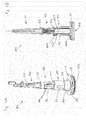
Fig. 3 is a centre longitudinal cut through an oral hygiene device with anattachment 100 as shown inFig. 2 being coupled to a handle 10 (thehandle 10 is only partly shown). Thehandle 10 has a drive shaft 11 that extends out of thehandle 10. Aneck section 12 extending from the handle housing surrounds the drive shaft 11 for a certain length. Theinsert part 110 and theneck section 12 may be designed so as to positively fit into each other. The drive shaft 11 is coupled to a drive unit disposed within the handle so that it can be driven into an oscillatory rotation around a longitudinal axis 11A. Theneck section 12 of thehandle 10 and the extending portion of the drive shaft 11 are disposed in the shown attached state in thecavity 102 of theattachment 100. Thecavity 102 is defined by thehollow insert part 110, the hollowflexible sealing element 120 and the partlyhollow shaft element 130. Theflexible sealing element 120 is on a first side attached to theshaft element 130 via aconnector structure 129 that encloses theshaft element 130 so as to form a watertight connection. Theflexible sealing element 120 is on a second side attached to theinsert part 110 via aconnector structure 121 that is connected to a ring-like front face 111 of theinsert part 110 so as to form a watertight connection. Theintegral part 101 comprisingshaft element 130,flexible sealing element 120, and insertpart 110 may be manufactured as a two-component (or multi-component) plastic injection molding part. In a first step theinsert part 110 and theshaft element 130 may be made from a hard plastic material such as PP (polypropylene) or ASA (acrylonitrile styrene acrylate) either in a single cavity or in two separate cavities and in a second step, theflexible sealing element 120 may be injection molded onto theinsert part 110 and theshaft element 130 using a soft thermoplastic material such a thermoplastic elastomer (TPE). The hard plastic material and the thermoplastic material may in particular be chosen such that they enter into a watertight material bond at the connection surfaces. In an embodiment, the shaft element and/or the insert part may be made from a reinforced plastic material, e.g. a glass fiber reinforced PP. In another embodiment, the flexible sealing element is made from a rubber foil and is glued to the insert part and the shaft element. - Generally it is to be stated that the flexible sealing element may in another embodiment be attached to a shaft element and may be further attached to, e.g., the housing of the attachment to thus seal the cavity against liquid. The insert part as shown in the example embodiments allows for relatively easy mounting of the parts whereas a direct attachment of the flexible sealing element to a part of the housing does not require as many separate parts as in the shown example embodiment. Further, the coupling structure 115 (being an optional feature) may be realized integral with the housing.
- In the shown example embodiment, the drive shaft 11 has a flat front part 11B (which means that the front part has a non-circular cross section) that positively fits - essentially play-free - with a
coupling section 131 of the shaft element 130 (whichcoupling section 131 is here a recess in theshaft element 130 and forms a part of the cavity 102). Hence, when the drive shaft 11 is driven into an oscillatory rotation around the longitudinal axis 11A by the drive unit during operation, the drive shaft 11 then takes along theshaft element 130 and the shaft element follows the movement of the drive shaft around the longitudinal axis 11A. Theshaft element 130 is mounted at thehousing 180 via a mounting element 140 (which may be realized as a metal mounting pin), which mountingelement 140 extends along the longitudinal axis 11A such that oscillatory rotation of theshaft element 130 around the longitudinal axis 11A is enabled when the drive shaft 11 takes along theshaft element 130. An actuation element 150 (which may be realized as a metal actuation pin) is mounted at theshaft element 130 at mounting bores 132 so as to be movable in longitudinal direction (i.e. along an actuation element axis that is parallel to the longitudinal axis 11A). A coupling element 151 is coupled to the actuation element 150 (e.g. the coupling element may be realized as a metal pin that is welded to theactuation element 150 so that a T-like actuation-coupling-structure results) and sits in a transverse bore in a carrier structure of theoral cleaning unit 190. When theshaft element 130 oscillates around the longitudinal axis 11A, then the eccentrically mountedactuation element 150 moves along a circular segment and thereby oscillates theoral cleaning section 190 around its centre axis 190A. During the oscillation, theactuation element 150 slightly moves along the longitudinal direction. Astopper element 139 made from an elastomeric material may be in contact with theactuation element 150 and whenever the drive shaft is not moved, then thestopper element 139 essentially inhibits a free movement of theactuation element 150 due to friction between theactuation element 150 and thestopper element 139 and clattering noises generated by an otherwise freely movable attachment in a non-driven state are reduced. - In accordance with an aspect of the present disclosure, the
stopper element 139 may be considered as a feature of individual value. Hence, in accordance with this aspect, an attachment for an oral hygiene device is provided that comprises at least a movable actuation element that is in frictional contact with a stopper element to reduce free motion of the movable actuation element in a non-driven state. Any other feature as discussed in the present disclosure may be individually combined with this aspect. - In the example embodiment shown in
Fig. 3 , theinsert part 101 is integral with acoupling structure 115 that radially extends around the end of theattachment 100 proximal thehandle 10 in the attached state. Thecoupling structure 115 here comprises a negative snap-ring structure 116 that mates with a respective positive snap-ring structure 221 of acoupling structure 220 of apouch 200. A sealingelement 119 is here provided in the negative snap-ring structure 116 such that the mated snap-ring structures 116 and 221 form a watertight connection. The sealingelement 119 may be realized by an O-ring or the sealingelement 119 may be an injection molded part. Thepouch 200 comprises apouch body 210 that may be realized as a thin plastic foil (e.g. made from polyester) that may be transparent. Thepouch body 210 is attached to thecoupling structure 220 in a watertight manner. Thepouch 200 may fully enclose thehandle 10 while it allows for undisturbed operation (e.g. pushing of an on/off button etc.) of thehandle 10 by a user during operation. In an embodiment, thepouch 200 has a further sealable opening at the other end (not shown) and thepouch body 210 is dimensioned to completely accommodate thehandle 10. In use, the user may first couple the pouch on one end to the attachment and then slide the handle into thepouch 200 via the sealable opening at its other end until the drive shaft enters the cavity in the attachment and couples with the shaft element. Then the user may seal the sealable end of the pouch body and can use the oral hygiene device essentially without fear of contaminating any part of the handle. A sanitizing step may thus not be necessary after use if the handle is to be used by several users, e.g. during a clinical test, but the next user just uses its own attachment and pouch. Thepouch 200 may comprise a sanitary coating such as an antimicrobial coating on its inner and/or on its outer surface. - As has been said before, the
flexible sealing member 120 is utilized to seal the cavity 102 (i.e. the drive shaft 11 and also theneck section 12 when theattachment 100 is attached to the handle 10) against contamination by germs (bacteria etc.) during operation. In particular, as can be seen in the example embodiment shown inFig. 3 , a gap 13 may exist between the drive shaft 11 and theneck section 12 such that contaminated liquids may enter into this gap 13. The gap 13 is particularly hard to clean and sanitizing thehandle 10 after use may not be simply possible. Thepouch 200 has a twofold function. It envelopes and thus effectively seals thewhole handle 10 against contamination by germs or bacteria that may be present on the skin of the hand of a user. Further, as thepouch 200 is also coupled to theattachment 100 in a watertight manner (and thus may be considered to form a part of the attachment), any liquids (e.g. saliva) comprising germs or bacteria are efficiently inhibited to enter thecavity 102 from the side of thehandle 10. In another embodiment, a sealing structure may be arranged at the attachment such that it seals the attachment against the handle in the attached state. In another embodiment, the pouch may be directly connected to the attachment (e.g. by gluing) - It is to be noted that the example embodiment shown in
Figs. 2 and3 shows several features that are optional with respect to an aspect of the present disclosure. According to this aspect, a movably arranged shaft element (which may be integral with an oral hygiene unit) is arranged, which shaft element is coupled to a drive shaft of a handle of an oral hygiene device in the attached state, and a flexible sealing element seals a cavity accommodating at least a part of the drive shaft between the shaft element and a part of the attachment, where the shaft element will perform a repetitive (in particular: oscillating) motion relative to the part of the attachment during operation (which does not mean that the attachment itself would be necessarily fixed relative to the handle but only that the flexible sealing element is arranged between two parts that will perform relative motion during operation). All other features may individually (where appropriate) or in arbitrary combination be added. -
Fig. 4A is a perspective view onto theintegral part 101 as discussed with respect to the example embodiment shown inFigs. 2 and3 . Theintegral part 101 may be manufactured using two-component (or multi-component) plastic injection molding technology as was explained above. Theintegral part 101 comprises aninsert part 110 that may - as shown here - be integral with a radially outwards extending ring-like coupling structure 115, aflexible sealing element 120, and ashaft element 130. Theflexible sealing element 120 may be attached to theshaft element 130 to a ring-shaped surface that encircles theshaft element 130 by aconnector structure 129 and may be attached to theinsert part 110 along a front face of the integral part via aconnector structure 121. Acentral portion 125 extends between the twoconnector structures central portion 125 has here longitudinally extendingribs 126 to enhance the ability of theflexible sealing element 120 to withstand maximum twists of e.g. about ±30 degrees around the longitudinal axis with respect to a rest position, in particular about ±25 degrees, about ±22 degrees, about ±20 degrees, about ±18 degrees, about ±16 degrees, or about ±10 degrees at least for about a period of two minutes or three minutes or four minutes at an oscillation frequency of between about 30 Hz to about 300 Hz. In another embodiment, where the drive shaft linearly oscillates, the flexible sealing element may be arranged to withstand longitudinal expansions and contractions of about ±0.1 mm to about ±2 mm around a rest position, in particular of about ±0.5 mm to about ±1.5 mm at an oscillation frequency of about 30 Hz to about 300 Hz. In yet another embodiment, the flexible sealing element may be structured to withstand combinations of twists and longitudinal expansions and contractions (an example embodiment is shown inFig. 5 ). Of course theflexible sealing element 120 may be designed to withstand the repetitive movements during operation for a much longer time period, but in case the attachment is intended for a single use (e.g. during a clinical trial) it would be sufficient if theflexible sealing element 120 seals reliably for a time period of a typical oral hygiene event (e.g. a tooth brushing event). FEM (finite elements method) simulations may be used to determine the material and the dimensions and geometrical structure of the flexible sealing element such that besides structural integrity it is also ensured that the flexible sealing element does not provide too much resistance such that a breakdown in oscillation angle and/or frequency is essentially avoided to achieve cleaning results and use feeling comparable to a similar attachment without a flexible sealing element. Theshaft element 130 may comprise astopper element 139 which is here used to provide a resistance against free movement of the actuation pin 150 (shown inFig. 3 ) when the device is not in operation. Theinsert part 110 may comprise a radially outwards projectingrib 112 for snapping theinsert part 110 into a respective recess in the housing of the attachment (this snap connection may be designed to be non-detachable to avoid that the integral part can be easily separated from the housing). Theinsert part 110 may further comprises a radially outwards projecting nose 114 to establish a lock-and-key feature to enhance correct positional coupling between theintegral part 101 and the housing of the attachment. The housing of the attachment hence may comprise a respective recess to accommodate the nose 114. Similarly, thecoupling structure 115 may comprise a cut-out 115A to establish a lock-and-key feature. Thecoupling structure 115 may also comprise a negative snap-ring structure 116 in which asealing element 116 is arranged. In addition, theinsert part 110 may comprise aspring element 113 that will be explained in more detail further below. -
Fig. 4B is a centre longitudinal cut through theintegral part 101 shown inFig. 4A , where the cut plane extends through the centre of thespring element 113. Thespring element 113 may be formed as a tongue element that is integral with theinsert part 110 at one end but that is coupled to theinsert part 110 at its sides and at its tip via anelastomeric material 113A. The elastomeric material on the one hand seals thespring element 113 against theinsert part 110 and on the other hand allows for a certain flexibility of thespring element 113 such that it can e.g. pivot outwards. Thespring element 113 may comprise a radially inwards extendingprojection 113B. When the attachment is attached to the handle, the neck section 12 (as shown inFig. 3 ) slides into the part of thecavity 102 formed by theinsert part 110. The neck section then forces thespring element 113 to pivot outwards by pushing against theprojection 113B. In return, thespring element 113 clamps the attachment to the neck section to inhibit easy separation of the attachment from the handle. - It can be seen in
Fig. 4B that the sealingelement 119 of thecoupling structure 115, theflexible sealing 113A of thespring element 113 and theflexible sealing element 120 may be made in the same injection molding step and that those elastomeric structures may be connected by connectingchannels 119A and 121A. Thestopper element 139 shown inFig. 4A may also be made in the same injection molding step from the same thermoplastic material and may be connected to theflexible sealing element 120 by a further connecting channel. - When the
integral part 101 is mounted into the housing of the attachment, the mounting element and the actuation element may be mounted to theshaft element 130 and then the integral part may be slid into the hollow of the housing until the mounting element mates with the respective bore in the housing and simultaneously therib 112 mates with the respective recess in the housing. -
Fig. 5 is a perspective view onto a different example embodiment of anintegral part 101A similar to the integral part shown inFig. 4A . Here, theflexible sealing element 120A comprises abellows structure 127A (here realized as a gaiter) that is structured to withstand repetitive linear oscillations of theshaft element 130A with respect to theinsert part 110A along the longitudinal axis as indicated by the double arrow L. Linear oscillations around a rest position may have maximum amplitudes of between about ±0.1 mm to about ±2.0 mm. Thebellows structure 127A expands and contracts during these oscillations. In the shown embodiment, thebellows structure 127A is realized in addition to atorsion withstanding part 125A of theflexible sealing element 120A; in another embodiment only a bellows structure may be present. -
Fig. 6 is a schematic depiction of an example embodiment of a pouch 200A as proposed. The pouch 200A comprises apouch body 210A (e.g. a (low-density) polyester ((LD)PE) or polypropylene (PP) bag) that has a sealable or re-sealable opening 211A (in one embodiment this may be essentially realized as in a (re-)sealable plastic zip pouch or pressure seal pouch; in another embodiment the sealing may be realized by adhesion, e.g. as an adhesive seal pouch) at one end to receive the handle of an oral hygiene device and aconnector structure 220A arranged at a second end such that at least a drive shaft of a handle can extend through theconnector structure 220A as was explained further above with reference toFig. 3 . In the shown embodiment, a re-sealable closure is achieved by a slide fastener 212A (or: pressure closure). Theconnector structure 220A is attached to thepouch body 210A by any suitable means, e.g. by clamping, gluing or (laser) welding and is intended for connection with a respective connector structure at the attachment. -
Fig. 7 is a perspective view onto a further example embodiment of an integral part 101C that comprises a shaft element 130C, aflexible sealing element 120C, and aninsert element 110C. The shaft element 130C is intended for oscillatory rotation R (indicated by a double arrow) around the longitudinal extension direction relative to theinsert element 110C, which insertelement 110C is intended to be fixedly mounted into a housing of an attachment (seeFig. 8 ). Theflexible sealing element 120C connects theinsert element 110C and the shaft element 130C and is intended to withhold the repetitive relative motion of the shaft element 130C with respect to theinsert element 110C during operation. Theflexible sealing element 120C may comprise a ring-like, radially outwards extending sealing structure 122C. Theflexible sealing element 120C has aconnector structure 121C with which it is connected to insertstructure 110C, whichconnector structure 121C extends as a continuation of thecylindrical insert structure 110C. Theconnector structure 121C is intended to be in snug contact with the inner wall of a housing of an attachment comprising the integral structure 101C such that by the snug contact a liquid-tight contact is established (as will be discussed with reference toFig. 8 ). Theflexible sealing element 120C has a further connector structure 129C with which it is connected to the shaft element 130C. -
Fig. 8 shows a cross-sectional cut through an example embodiment of anattachment 100C (only partially assembled) that comprises an integral element 101C as shown inFig. 7 . Theattachment 100C may comprise an oral cleaning unit 190C. Aninsert element 110C is fixedly mounted at a housing 180C of theattachment 100C. Aflexible sealing element 120C that is coupled to theinsert element 110C by material engagement connects theinsert element 110C with a shaft element 130C, which shaft element 130C is movably mounted within the housing 180C. Theinsert element 110C, theflexible sealing element 120C and theshaft element 120C define a hollow 102C that is intended to receive a drive shaft of a handle of an oral hygiene device as was discussed with reference toFig. 3 . As was explained above, in an attached state the drive shaft is mechanically coupled to theshaft element 110C and may transfer during operation repetitive motion to the shaft element 130C (in particular oscillatory rotational or linear vibration motion), which shaft element 130C would then perform a relative oscillatory motion with respect to theinsert element 110C and thus also with respect to the housing 180C. In some embodiments, theflexible sealing element 120C may be intended to withstand maximum twists of e.g. about ±30 degrees around the longitudinal axis with respect to a rest position, in particular about ±25 degrees, about ±22 degrees, about ±20 degrees, about ±18 degrees, about ±16 degrees, or about ±10 degrees at least for about a period of two minutes or three minutes or four minutes or five minutes or six minutes at an oscillation frequency of between about 30 Hz to about 300 Hz. - In the example embodiment discussed with reference to
Figs. 7 and8 in particular but also more generally, an additional pouch may not be needed if a neck section of a handle (seeFig. 3 ) extending into the cavity 102C may snugly fit into this lower portion of the cavity such that theflexible sealing element 120C forms a liquid-tight sealing enclosure. Thus, the drive shaft is effectively protected from soiling during operation. In the example embodiment shown inFigs. 7 and8 , the ring-like sealing structure 122C may be squeezed into a ring-like groove 182C in the attachment housing to even enhance the liquid-tight sealing function of the flexible sealing element. - It is to be stated that the features as disclosed may be individually combined in all possible combinations that fall within the gist and scope of the present disclosure in accordance with any of its aspects and that none of the example embodiments shall be interpreted in a way to limit the disclosure to specific combinations of features that happen to be disclosed in combination for a given example embodiment.
- The dimensions and values disclosed herein are not to be understood as being strictly limited to the exact numerical values recited. Instead, unless otherwise specified, each such dimension is intended to mean both the recited value and a functionally equivalent range surrounding that value. For example, a dimension disclosed as "40 mm" is intended to mean "about 40 mm."
Claims (15)
- Attachment for an oral hygiene device, comprising:a housing;a shaft element movably arranged within the housing and arranged for being coupled to a drive shaft of a handle of the oral hygiene device; anda flexible sealing element, in particular made from an elastic material such as a natural or artificial rubber or a thermoplastic elastomer, attached to the shaft element, which flexible sealing element is arranged to seal a cavity within the attachment intended for accommodating at least a part of the drive shaft in an attached state.
- The attachment according to claim 1, wherein the flexible sealing element is also attached to the housing and extends between the housing and the shaft element, in particular wherein the flexible sealing element spans 360 degrees between the shaft element and the housing.
- The attachment according to claim 1 or claim 2, wherein the cavity extends in a longitudinal direction from a proximal end, where the cavity has an opening to receive the drive shaft when being attached to the handle to a distal end that is located within the shaft element.
- The attachment according to claim 3, wherein the flexible sealing element extends in the longitudinal direction and forms an enclosure of at least a part of the cavity.
- The attachment according to any one of claims 1 to 4, wherein the flexible sealing element comprises at least a longitudinal rib structure or a bellows structure.
- The attachment according to any one of claims 1 to 5, wherein the flexible sealing element is attached to an insert part that is fixedly mounted at the housing.
- The attachment according to claim 6, wherein the shaft element, the flexible sealing element and the insert part are realized as an integral part, in particular as a two-component or multi-component plastic injection molding part.
- The attachment according to any one of claims 1 to 7, wherein a coupling structure is arranged at the attachment, in particular at the open end of the cavity, which coupling structure at least partly encircles the opening of the cavity.
- The attachment according to any one of claims 1 to 8, further comprising a movably mounted oral cleaning unit coupled to the shaft element, the attachment in particular being realized as a replacement brush head for an electric toothbrush.
- The attachment according to any one of claims 1 to 9, wherein a pouch for covering the handle of the oral hygiene device in the attached state is coupled to the attachment.
- The attachment according to claim 10 with reference to claim 8, wherein the pouch has a coupling structure that mates with the coupling structure at the attachment and at least one of the coupling structures comprising a sealing element.
- The attachment according to any one of claims 1 to 10, wherein the shaft element is arranged to be driven into a repetitive motion, in particular an oscillatory rotation around the longitudinal axis of the attachment with a deflection angle of between about ±5 degrees to about ±30 degrees or a linear vibration along the longitudinal axis of the attachment with a peak elongation of between about ±0.05 mm to about ±2.0 mm.
- Pouch for an oral hygiene device comprising a pouch body for covering at least a handle of the oral hygiene device, wherein the pouch has at least a sealable opening for receiving the handle and a second opening through which at least a drive shaft of the handle can extend when the pouch is covering the handle.
- Oral hygiene device comprising at least an attachment in accordance with any one of claims 1 to 11 attached to a handle of the oral care device.
- Kit comprising:at least an attachment in accordance with any one of claims 1 to 9;at least a pouch in accordance with claim 12.
Priority Applications (7)
| Application Number | Priority Date | Filing Date | Title |
|---|---|---|---|
| PL12151348T PL2478865T3 (en) | 2011-01-25 | 2012-01-17 | Attachment for an oral hygiene device |
| EP12151348.5A EP2478865B1 (en) | 2011-01-25 | 2012-01-17 | Attachment for an oral hygiene device |
| CN201280006348.0A CN103327933B (en) | 2011-01-25 | 2012-01-25 | For the attachment of oral hygiene device |
| CA2825596A CA2825596C (en) | 2011-01-25 | 2012-01-25 | Attachment for an oral hygiene device |
| JP2013550992A JP5847847B2 (en) | 2011-01-25 | 2012-01-25 | Attachment for oral hygiene device |
| PCT/IB2012/050352 WO2012101590A1 (en) | 2011-01-25 | 2012-01-25 | Attachment for an oral hygiene device |
| MX2013008585A MX2013008585A (en) | 2011-01-25 | 2012-01-25 | Attachment for an oral hygiene device. |
Applications Claiming Priority (2)
| Application Number | Priority Date | Filing Date | Title |
|---|---|---|---|
| EP11000558 | 2011-01-25 | ||
| EP12151348.5A EP2478865B1 (en) | 2011-01-25 | 2012-01-17 | Attachment for an oral hygiene device |
Publications (2)
| Publication Number | Publication Date |
|---|---|
| EP2478865A1 true EP2478865A1 (en) | 2012-07-25 |
| EP2478865B1 EP2478865B1 (en) | 2014-12-17 |
Family
ID=44168874
Family Applications (1)
| Application Number | Title | Priority Date | Filing Date |
|---|---|---|---|
| EP12151348.5A Active EP2478865B1 (en) | 2011-01-25 | 2012-01-17 | Attachment for an oral hygiene device |
Country Status (10)
| Country | Link |
|---|---|
| US (1) | US9561092B2 (en) |
| EP (1) | EP2478865B1 (en) |
| JP (1) | JP5847847B2 (en) |
| CN (1) | CN103327933B (en) |
| CA (1) | CA2825596C (en) |
| DK (1) | DK2478865T3 (en) |
| ES (1) | ES2532368T3 (en) |
| MX (1) | MX2013008585A (en) |
| PL (1) | PL2478865T3 (en) |
| WO (1) | WO2012101590A1 (en) |
Cited By (8)
| Publication number | Priority date | Publication date | Assignee | Title |
|---|---|---|---|---|
| CN110151348A (en) * | 2019-03-14 | 2019-08-23 | 胡斐凡 | A kind of brush head assembly and electric toothbrush |
| US10603150B2 (en) | 2017-12-12 | 2020-03-31 | Colgate-Palmolive Company | Oral care implement |
| US10603147B2 (en) | 2017-12-12 | 2020-03-31 | Colgate-Palmolive Company | Oral care implement |
| US10631964B2 (en) | 2017-12-12 | 2020-04-28 | Colgate-Palmolive Company | Oral care implement |
| US10639133B2 (en) | 2017-12-12 | 2020-05-05 | Colgate-Palmolive Company | Oral care implement and handle and refill head thereof |
| US10709533B2 (en) | 2017-12-12 | 2020-07-14 | Colgate-Palmolive Company | Oral care implement and handle and refill head thereof |
| USD960582S1 (en) | 2020-12-10 | 2022-08-16 | Colgate-Palmolive Company | Oral care refill head |
| USD997567S1 (en) | 2018-12-18 | 2023-09-05 | Colgate-Palmolive Company | Electric toothbrush |
Families Citing this family (14)
| Publication number | Priority date | Publication date | Assignee | Title |
|---|---|---|---|---|
| US9439741B2 (en) | 2014-03-14 | 2016-09-13 | Ranir, Llc | Replacement brush head for an electric toothbrush |
| AU367234S (en) | 2015-08-07 | 2016-02-19 | Braun Gmbh | Electric toothbrush handle |
| WO2018085484A1 (en) | 2016-11-03 | 2018-05-11 | Papazian Mihran | Replacement toothbrush head assembly for toothbrushing systems |
| CN206979072U (en) * | 2017-04-25 | 2018-02-09 | 创科(澳门离岸商业服务)有限公司 | Oral care implement and its nursing head |
| CN109223230B (en) * | 2017-07-11 | 2020-09-25 | Js控股股份有限公司 | Removable brush head for a power toothbrush |
| USD893881S1 (en) | 2017-11-17 | 2020-08-25 | Colgate-Palmolive Company | Oral care apparatus |
| USD858105S1 (en) | 2017-11-17 | 2019-09-03 | Colgate-Palmolive Company | Oral care implement |
| USD858997S1 (en) | 2017-11-17 | 2019-09-10 | Colgate-Palmolive Company | Tracking module for an oral care implement |
| USD922775S1 (en) | 2018-12-06 | 2021-06-22 | Braun Gmbh | Electric toothbrush handle |
| US11406480B2 (en) * | 2019-12-19 | 2022-08-09 | Colgate-Palmolive Company | Oral care implement and refill head thereof |
| US11484253B2 (en) | 2019-12-19 | 2022-11-01 | Colgate-Palmolive Company | Oral care system |
| USD972302S1 (en) | 2020-03-13 | 2022-12-13 | Ranir, Llc | Toothbrush drive unit |
| USD1014977S1 (en) | 2021-03-25 | 2024-02-20 | The Gillette Company Llc | Handle for battery operated toothbrush |
| US20220401200A1 (en) * | 2021-06-16 | 2022-12-22 | Davor Hrboka | Electric Toothbrush Base Protector |
Citations (3)
| Publication number | Priority date | Publication date | Assignee | Title |
|---|---|---|---|---|
| US6367108B1 (en) * | 1997-10-17 | 2002-04-09 | Braun Gmbh | Brush section for an electric toothbrush |
| WO2009036462A2 (en) * | 2007-09-14 | 2009-03-19 | Discus Dental, Llc | Dental prophylaxis devices |
| US20090162811A1 (en) * | 2007-12-20 | 2009-06-25 | Benjamin Chronister | Dental prophylaxis angle and handpiece assembly |
Family Cites Families (12)
| Publication number | Priority date | Publication date | Assignee | Title |
|---|---|---|---|---|
| US2628377A (en) * | 1950-03-21 | 1953-02-17 | Floyd M Cockriel | Mechanical toothbrush |
| US4235253A (en) * | 1979-05-07 | 1980-11-25 | Moore Dawne A | Electric dental flosser |
| US5209658A (en) * | 1992-07-13 | 1993-05-11 | Brahler Products, Inc. | Dental prophy angle |
| US6422867B2 (en) * | 1999-12-21 | 2002-07-23 | Water Pik, Inc. | Interproximal flosser handle |
| JP4443116B2 (en) * | 2001-03-14 | 2010-03-31 | ブラウン ゲーエムベーハー | Teeth cleaning method and apparatus |
| CN1307950C (en) * | 2001-03-14 | 2007-04-04 | 布劳恩有限公司 | Device for cleaning teeth |
| CN2614647Y (en) * | 2003-03-20 | 2004-05-12 | 邝美琪 | Moving connectnig rod electric tooth brush |
| US7614107B2 (en) * | 2004-01-02 | 2009-11-10 | Sonicscrubbers, Llc | Cleaning apparatus with reciprocating brush head |
| US7784138B2 (en) * | 2005-02-16 | 2010-08-31 | Hayco Manufacturing Limited | Device for converting a rotating motion into a reciprocating motion and an electric tool assembly having such a device |
| US20090019649A1 (en) * | 2007-07-18 | 2009-01-22 | Brushpoint Innovations Inc. | Electric toothbrush |
| US8136192B2 (en) * | 2009-03-24 | 2012-03-20 | Harrison Hygiene Inc. | Head for a powered denture brush and a denture brush incorporating the same |
| CN201676033U (en) * | 2010-05-31 | 2010-12-22 | 罗宁 | Acoustic vibration structure of electric toothbrush |
-
2012
- 2012-01-17 ES ES12151348.5T patent/ES2532368T3/en active Active
- 2012-01-17 EP EP12151348.5A patent/EP2478865B1/en active Active
- 2012-01-17 PL PL12151348T patent/PL2478865T3/en unknown
- 2012-01-17 DK DK12151348T patent/DK2478865T3/en active
- 2012-01-24 US US13/356,831 patent/US9561092B2/en active Active
- 2012-01-25 JP JP2013550992A patent/JP5847847B2/en active Active
- 2012-01-25 MX MX2013008585A patent/MX2013008585A/en not_active Application Discontinuation
- 2012-01-25 WO PCT/IB2012/050352 patent/WO2012101590A1/en active Application Filing
- 2012-01-25 CA CA2825596A patent/CA2825596C/en active Active
- 2012-01-25 CN CN201280006348.0A patent/CN103327933B/en active Active
Patent Citations (3)
| Publication number | Priority date | Publication date | Assignee | Title |
|---|---|---|---|---|
| US6367108B1 (en) * | 1997-10-17 | 2002-04-09 | Braun Gmbh | Brush section for an electric toothbrush |
| WO2009036462A2 (en) * | 2007-09-14 | 2009-03-19 | Discus Dental, Llc | Dental prophylaxis devices |
| US20090162811A1 (en) * | 2007-12-20 | 2009-06-25 | Benjamin Chronister | Dental prophylaxis angle and handpiece assembly |
Cited By (11)
| Publication number | Priority date | Publication date | Assignee | Title |
|---|---|---|---|---|
| US10603150B2 (en) | 2017-12-12 | 2020-03-31 | Colgate-Palmolive Company | Oral care implement |
| US10603147B2 (en) | 2017-12-12 | 2020-03-31 | Colgate-Palmolive Company | Oral care implement |
| US10631964B2 (en) | 2017-12-12 | 2020-04-28 | Colgate-Palmolive Company | Oral care implement |
| US10639133B2 (en) | 2017-12-12 | 2020-05-05 | Colgate-Palmolive Company | Oral care implement and handle and refill head thereof |
| US10709533B2 (en) | 2017-12-12 | 2020-07-14 | Colgate-Palmolive Company | Oral care implement and handle and refill head thereof |
| US11517412B2 (en) | 2017-12-12 | 2022-12-06 | Colgate-Palmolive Company | Oral care implement |
| US11833004B2 (en) | 2017-12-12 | 2023-12-05 | Colgate-Palmolive Company | Oral care implement and handle and refill head thereof |
| USD997567S1 (en) | 2018-12-18 | 2023-09-05 | Colgate-Palmolive Company | Electric toothbrush |
| CN110151348A (en) * | 2019-03-14 | 2019-08-23 | 胡斐凡 | A kind of brush head assembly and electric toothbrush |
| CN110151348B (en) * | 2019-03-14 | 2024-04-19 | 胡斐凡 | Brush head assembly and electric toothbrush |
| USD960582S1 (en) | 2020-12-10 | 2022-08-16 | Colgate-Palmolive Company | Oral care refill head |
Also Published As
| Publication number | Publication date |
|---|---|
| DK2478865T3 (en) | 2015-03-23 |
| US9561092B2 (en) | 2017-02-07 |
| ES2532368T3 (en) | 2015-03-26 |
| PL2478865T3 (en) | 2015-05-29 |
| CA2825596A1 (en) | 2012-08-02 |
| JP2014504524A (en) | 2014-02-24 |
| WO2012101590A1 (en) | 2012-08-02 |
| US20130134062A1 (en) | 2013-05-30 |
| MX2013008585A (en) | 2013-10-25 |
| CA2825596C (en) | 2015-12-22 |
| CN103327933B (en) | 2016-06-01 |
| JP5847847B2 (en) | 2016-01-27 |
| CN103327933A (en) | 2013-09-25 |
| EP2478865B1 (en) | 2014-12-17 |
Similar Documents
| Publication | Publication Date | Title |
|---|---|---|
| EP2478865B1 (en) | Attachment for an oral hygiene device | |
| US11517412B2 (en) | Oral care implement | |
| EP3892234B1 (en) | Handle for an electrically operated personal care implement and personal care implement | |
| EP3892233B1 (en) | Unit for a handle of a personal care implement and personal care implement | |
| US10603150B2 (en) | Oral care implement | |
| KR20220073797A (en) | Handles for electric personal care appliances | |
| AU2021253692B2 (en) | Handle for a personal care implement and personal care implement | |
| EP3892236B1 (en) | Handle for an electrically operated personal oral care implement and personal oral care implement | |
| AU3697399A (en) | Tooth brush | |
| JP2016531609A (en) | Oral hygiene device and oral hygiene device provided with oral hygiene device |
Legal Events
| Date | Code | Title | Description |
|---|---|---|---|
| PUAI | Public reference made under article 153(3) epc to a published international application that has entered the european phase |
Free format text: ORIGINAL CODE: 0009012 |
|
| AK | Designated contracting states |
Kind code of ref document: A1 Designated state(s): AL AT BE BG CH CY CZ DE DK EE ES FI FR GB GR HR HU IE IS IT LI LT LU LV MC MK MT NL NO PL PT RO RS SE SI SK SM TR |
|
| AX | Request for extension of the european patent |
Extension state: BA ME |
|
| 17P | Request for examination filed |
Effective date: 20130123 |
|
| GRAP | Despatch of communication of intention to grant a patent |
Free format text: ORIGINAL CODE: EPIDOSNIGR1 |
|
| INTG | Intention to grant announced |
Effective date: 20140725 |
|
| GRAS | Grant fee paid |
Free format text: ORIGINAL CODE: EPIDOSNIGR3 |
|
| GRAA | (expected) grant |
Free format text: ORIGINAL CODE: 0009210 |
|
| AK | Designated contracting states |
Kind code of ref document: B1 Designated state(s): AL AT BE BG CH CY CZ DE DK EE ES FI FR GB GR HR HU IE IS IT LI LT LU LV MC MK MT NL NO PL PT RO RS SE SI SK SM TR |
|
| REG | Reference to a national code |
Ref country code: GB Ref legal event code: FG4D |
|
| REG | Reference to a national code |
Ref country code: CH Ref legal event code: EP |
|
| REG | Reference to a national code |
Ref country code: IE Ref legal event code: FG4D |
|
| REG | Reference to a national code |
Ref country code: AT Ref legal event code: REF Ref document number: 701304 Country of ref document: AT Kind code of ref document: T Effective date: 20150115 |
|
| REG | Reference to a national code |
Ref country code: DE Ref legal event code: R096 Ref document number: 602012004281 Country of ref document: DE Effective date: 20150129 |
|
| REG | Reference to a national code |
Ref country code: DK Ref legal event code: T3 Effective date: 20150317 |
|
| REG | Reference to a national code |
Ref country code: NL Ref legal event code: T3 |
|
| REG | Reference to a national code |
Ref country code: ES Ref legal event code: FG2A Ref document number: 2532368 Country of ref document: ES Kind code of ref document: T3 Effective date: 20150326 |
|
| REG | Reference to a national code |
Ref country code: SE Ref legal event code: TRGR |
|
| PG25 | Lapsed in a contracting state [announced via postgrant information from national office to epo] |
Ref country code: NO Free format text: LAPSE BECAUSE OF FAILURE TO SUBMIT A TRANSLATION OF THE DESCRIPTION OR TO PAY THE FEE WITHIN THE PRESCRIBED TIME-LIMIT Effective date: 20150317 Ref country code: LT Free format text: LAPSE BECAUSE OF FAILURE TO SUBMIT A TRANSLATION OF THE DESCRIPTION OR TO PAY THE FEE WITHIN THE PRESCRIBED TIME-LIMIT Effective date: 20141217 |
|
| REG | Reference to a national code |
Ref country code: LT Ref legal event code: MG4D |
|
| PG25 | Lapsed in a contracting state [announced via postgrant information from national office to epo] |
Ref country code: LV Free format text: LAPSE BECAUSE OF FAILURE TO SUBMIT A TRANSLATION OF THE DESCRIPTION OR TO PAY THE FEE WITHIN THE PRESCRIBED TIME-LIMIT Effective date: 20141217 Ref country code: GR Free format text: LAPSE BECAUSE OF FAILURE TO SUBMIT A TRANSLATION OF THE DESCRIPTION OR TO PAY THE FEE WITHIN THE PRESCRIBED TIME-LIMIT Effective date: 20150318 Ref country code: HR Free format text: LAPSE BECAUSE OF FAILURE TO SUBMIT A TRANSLATION OF THE DESCRIPTION OR TO PAY THE FEE WITHIN THE PRESCRIBED TIME-LIMIT Effective date: 20141217 Ref country code: RS Free format text: LAPSE BECAUSE OF FAILURE TO SUBMIT A TRANSLATION OF THE DESCRIPTION OR TO PAY THE FEE WITHIN THE PRESCRIBED TIME-LIMIT Effective date: 20141217 |
|
| REG | Reference to a national code |
Ref country code: PL Ref legal event code: T3 |
|
| PG25 | Lapsed in a contracting state [announced via postgrant information from national office to epo] |
Ref country code: CZ Free format text: LAPSE BECAUSE OF FAILURE TO SUBMIT A TRANSLATION OF THE DESCRIPTION OR TO PAY THE FEE WITHIN THE PRESCRIBED TIME-LIMIT Effective date: 20141217 Ref country code: EE Free format text: LAPSE BECAUSE OF FAILURE TO SUBMIT A TRANSLATION OF THE DESCRIPTION OR TO PAY THE FEE WITHIN THE PRESCRIBED TIME-LIMIT Effective date: 20141217 Ref country code: SK Free format text: LAPSE BECAUSE OF FAILURE TO SUBMIT A TRANSLATION OF THE DESCRIPTION OR TO PAY THE FEE WITHIN THE PRESCRIBED TIME-LIMIT Effective date: 20141217 Ref country code: RO Free format text: LAPSE BECAUSE OF FAILURE TO SUBMIT A TRANSLATION OF THE DESCRIPTION OR TO PAY THE FEE WITHIN THE PRESCRIBED TIME-LIMIT Effective date: 20141217 |
|
| PG25 | Lapsed in a contracting state [announced via postgrant information from national office to epo] |
Ref country code: LU Free format text: LAPSE BECAUSE OF FAILURE TO SUBMIT A TRANSLATION OF THE DESCRIPTION OR TO PAY THE FEE WITHIN THE PRESCRIBED TIME-LIMIT Effective date: 20150117 Ref country code: IS Free format text: LAPSE BECAUSE OF FAILURE TO SUBMIT A TRANSLATION OF THE DESCRIPTION OR TO PAY THE FEE WITHIN THE PRESCRIBED TIME-LIMIT Effective date: 20150417 |
|
| REG | Reference to a national code |
Ref country code: DE Ref legal event code: R097 Ref document number: 602012004281 Country of ref document: DE |
|
| PG25 | Lapsed in a contracting state [announced via postgrant information from national office to epo] |
Ref country code: MC Free format text: LAPSE BECAUSE OF FAILURE TO SUBMIT A TRANSLATION OF THE DESCRIPTION OR TO PAY THE FEE WITHIN THE PRESCRIBED TIME-LIMIT Effective date: 20141217 |
|
| PLBE | No opposition filed within time limit |
Free format text: ORIGINAL CODE: 0009261 |
|
| STAA | Information on the status of an ep patent application or granted ep patent |
Free format text: STATUS: NO OPPOSITION FILED WITHIN TIME LIMIT |
|
| REG | Reference to a national code |
Ref country code: IE Ref legal event code: MM4A |
|
| 26N | No opposition filed |
Effective date: 20150918 |
|
| REG | Reference to a national code |
Ref country code: FR Ref legal event code: PLFP Year of fee payment: 5 |
|
| PG25 | Lapsed in a contracting state [announced via postgrant information from national office to epo] |
Ref country code: IE Free format text: LAPSE BECAUSE OF NON-PAYMENT OF DUE FEES Effective date: 20150117 |
|
| REG | Reference to a national code |
Ref country code: AT Ref legal event code: UEP Ref document number: 701304 Country of ref document: AT Kind code of ref document: T Effective date: 20141217 |
|
| PG25 | Lapsed in a contracting state [announced via postgrant information from national office to epo] |
Ref country code: SI Free format text: LAPSE BECAUSE OF FAILURE TO SUBMIT A TRANSLATION OF THE DESCRIPTION OR TO PAY THE FEE WITHIN THE PRESCRIBED TIME-LIMIT Effective date: 20141217 |
|
| PG25 | Lapsed in a contracting state [announced via postgrant information from national office to epo] |
Ref country code: MT Free format text: LAPSE BECAUSE OF FAILURE TO SUBMIT A TRANSLATION OF THE DESCRIPTION OR TO PAY THE FEE WITHIN THE PRESCRIBED TIME-LIMIT Effective date: 20141217 |
|
| REG | Reference to a national code |
Ref country code: FR Ref legal event code: PLFP Year of fee payment: 6 |
|
| PG25 | Lapsed in a contracting state [announced via postgrant information from national office to epo] |
Ref country code: HU Free format text: LAPSE BECAUSE OF FAILURE TO SUBMIT A TRANSLATION OF THE DESCRIPTION OR TO PAY THE FEE WITHIN THE PRESCRIBED TIME-LIMIT; INVALID AB INITIO Effective date: 20120117 Ref country code: BG Free format text: LAPSE BECAUSE OF FAILURE TO SUBMIT A TRANSLATION OF THE DESCRIPTION OR TO PAY THE FEE WITHIN THE PRESCRIBED TIME-LIMIT Effective date: 20141217 Ref country code: SM Free format text: LAPSE BECAUSE OF FAILURE TO SUBMIT A TRANSLATION OF THE DESCRIPTION OR TO PAY THE FEE WITHIN THE PRESCRIBED TIME-LIMIT Effective date: 20141217 |
|
| PG25 | Lapsed in a contracting state [announced via postgrant information from national office to epo] |
Ref country code: CY Free format text: LAPSE BECAUSE OF FAILURE TO SUBMIT A TRANSLATION OF THE DESCRIPTION OR TO PAY THE FEE WITHIN THE PRESCRIBED TIME-LIMIT Effective date: 20141217 |
|
| PG25 | Lapsed in a contracting state [announced via postgrant information from national office to epo] |
Ref country code: PT Free format text: LAPSE BECAUSE OF FAILURE TO SUBMIT A TRANSLATION OF THE DESCRIPTION OR TO PAY THE FEE WITHIN THE PRESCRIBED TIME-LIMIT Effective date: 20150417 |
|
| PG25 | Lapsed in a contracting state [announced via postgrant information from national office to epo] |
Ref country code: TR Free format text: LAPSE BECAUSE OF FAILURE TO SUBMIT A TRANSLATION OF THE DESCRIPTION OR TO PAY THE FEE WITHIN THE PRESCRIBED TIME-LIMIT Effective date: 20141217 |
|
| REG | Reference to a national code |
Ref country code: FR Ref legal event code: PLFP Year of fee payment: 7 |
|
| PG25 | Lapsed in a contracting state [announced via postgrant information from national office to epo] |
Ref country code: MK Free format text: LAPSE BECAUSE OF FAILURE TO SUBMIT A TRANSLATION OF THE DESCRIPTION OR TO PAY THE FEE WITHIN THE PRESCRIBED TIME-LIMIT Effective date: 20141217 |
|
| PG25 | Lapsed in a contracting state [announced via postgrant information from national office to epo] |
Ref country code: AL Free format text: LAPSE BECAUSE OF FAILURE TO SUBMIT A TRANSLATION OF THE DESCRIPTION OR TO PAY THE FEE WITHIN THE PRESCRIBED TIME-LIMIT Effective date: 20141217 |
|
| P01 | Opt-out of the competence of the unified patent court (upc) registered |
Effective date: 20230430 |
|
| PGFP | Annual fee paid to national office [announced via postgrant information from national office to epo] |
Ref country code: GB Payment date: 20231130 Year of fee payment: 13 |
|
| PGFP | Annual fee paid to national office [announced via postgrant information from national office to epo] |
Ref country code: SE Payment date: 20231213 Year of fee payment: 13 Ref country code: NL Payment date: 20231215 Year of fee payment: 13 Ref country code: FR Payment date: 20231212 Year of fee payment: 13 Ref country code: FI Payment date: 20231218 Year of fee payment: 13 |
|
| PGFP | Annual fee paid to national office [announced via postgrant information from national office to epo] |
Ref country code: PL Payment date: 20231215 Year of fee payment: 13 Ref country code: BE Payment date: 20231219 Year of fee payment: 13 |
|
| PGFP | Annual fee paid to national office [announced via postgrant information from national office to epo] |
Ref country code: ES Payment date: 20240206 Year of fee payment: 13 |
|
| PGFP | Annual fee paid to national office [announced via postgrant information from national office to epo] |
Ref country code: AT Payment date: 20231227 Year of fee payment: 13 |
|
| PGFP | Annual fee paid to national office [announced via postgrant information from national office to epo] |
Ref country code: DE Payment date: 20231205 Year of fee payment: 13 Ref country code: CH Payment date: 20240202 Year of fee payment: 13 |
|
| PGFP | Annual fee paid to national office [announced via postgrant information from national office to epo] |
Ref country code: IT Payment date: 20231212 Year of fee payment: 13 Ref country code: DK Payment date: 20240111 Year of fee payment: 13 |