EP2478792B1 - System umfassend eine tragbare elektronische Vorrichtung und einen Halter - Google Patents
System umfassend eine tragbare elektronische Vorrichtung und einen Halter Download PDFInfo
- Publication number
- EP2478792B1 EP2478792B1 EP11183635.9A EP11183635A EP2478792B1 EP 2478792 B1 EP2478792 B1 EP 2478792B1 EP 11183635 A EP11183635 A EP 11183635A EP 2478792 B1 EP2478792 B1 EP 2478792B1
- Authority
- EP
- European Patent Office
- Prior art keywords
- electronic device
- handheld electronic
- infrared
- container
- examples
- Prior art date
- Legal status (The legal status is an assumption and is not a legal conclusion. Google has not performed a legal analysis and makes no representation as to the accuracy of the status listed.)
- Active
Links
Images


Classifications
-
- A—HUMAN NECESSITIES
- A45—HAND OR TRAVELLING ARTICLES
- A45C—PURSES; LUGGAGE; HAND CARRIED BAGS
- A45C11/00—Receptacles for purposes not provided for in groups A45C1/00-A45C9/00
-
- G—PHYSICS
- G06—COMPUTING OR CALCULATING; COUNTING
- G06F—ELECTRIC DIGITAL DATA PROCESSING
- G06F1/00—Details not covered by groups G06F3/00 - G06F13/00 and G06F21/00
- G06F1/16—Constructional details or arrangements
- G06F1/1613—Constructional details or arrangements for portable computers
- G06F1/1628—Enclosures for carrying portable computers with peripheral devices, e.g. cases for a laptop and a printer
-
- A—HUMAN NECESSITIES
- A45—HAND OR TRAVELLING ARTICLES
- A45F—TRAVELLING OR CAMP EQUIPMENT: SACKS OR PACKS CARRIED ON THE BODY
- A45F5/00—Holders or carriers for hand articles; Holders or carriers for use while travelling or camping
- A45F5/02—Fastening articles to the garment
-
- A—HUMAN NECESSITIES
- A45—HAND OR TRAVELLING ARTICLES
- A45F—TRAVELLING OR CAMP EQUIPMENT: SACKS OR PACKS CARRIED ON THE BODY
- A45F5/00—Holders or carriers for hand articles; Holders or carriers for use while travelling or camping
- A45F5/02—Fastening articles to the garment
- A45F5/021—Fastening articles to the garment to the belt
-
- G—PHYSICS
- G06—COMPUTING OR CALCULATING; COUNTING
- G06F—ELECTRIC DIGITAL DATA PROCESSING
- G06F1/00—Details not covered by groups G06F3/00 - G06F13/00 and G06F21/00
- G06F1/16—Constructional details or arrangements
- G06F1/1613—Constructional details or arrangements for portable computers
- G06F1/1626—Constructional details or arrangements for portable computers with a single-body enclosure integrating a flat display, e.g. Personal Digital Assistants [PDAs]
-
- G—PHYSICS
- G06—COMPUTING OR CALCULATING; COUNTING
- G06F—ELECTRIC DIGITAL DATA PROCESSING
- G06F3/00—Input arrangements for transferring data to be processed into a form capable of being handled by the computer; Output arrangements for transferring data from processing unit to output unit, e.g. interface arrangements
- G06F3/01—Input arrangements or combined input and output arrangements for interaction between user and computer
- G06F3/03—Arrangements for converting the position or the displacement of a member into a coded form
- G06F3/0304—Detection arrangements using opto-electronic means
- G06F3/0317—Detection arrangements using opto-electronic means in co-operation with a patterned surface, e.g. absolute position or relative movement detection for an optical mouse or pen positioned with respect to a coded surface
-
- A—HUMAN NECESSITIES
- A45—HAND OR TRAVELLING ARTICLES
- A45C—PURSES; LUGGAGE; HAND CARRIED BAGS
- A45C11/00—Receptacles for purposes not provided for in groups A45C1/00-A45C9/00
- A45C11/002—Receptacles for purposes not provided for in groups A45C1/00-A45C9/00 for storing portable handheld communication devices, e.g. pagers or smart phones
-
- A—HUMAN NECESSITIES
- A45—HAND OR TRAVELLING ARTICLES
- A45F—TRAVELLING OR CAMP EQUIPMENT: SACKS OR PACKS CARRIED ON THE BODY
- A45F5/00—Holders or carriers for hand articles; Holders or carriers for use while travelling or camping
- A45F5/1516—Holders or carriers for portable handheld communication devices, e.g. pagers or smart phones
-
- G—PHYSICS
- G06—COMPUTING OR CALCULATING; COUNTING
- G06F—ELECTRIC DIGITAL DATA PROCESSING
- G06F2200/00—Indexing scheme relating to G06F1/04 - G06F1/32
- G06F2200/16—Indexing scheme relating to G06F1/16 - G06F1/18
- G06F2200/163—Indexing scheme relating to constructional details of the computer
- G06F2200/1633—Protecting arrangement for the entire housing of the computer
-
- Y—GENERAL TAGGING OF NEW TECHNOLOGICAL DEVELOPMENTS; GENERAL TAGGING OF CROSS-SECTIONAL TECHNOLOGIES SPANNING OVER SEVERAL SECTIONS OF THE IPC; TECHNICAL SUBJECTS COVERED BY FORMER USPC CROSS-REFERENCE ART COLLECTIONS [XRACs] AND DIGESTS
- Y10—TECHNICAL SUBJECTS COVERED BY FORMER USPC
- Y10S—TECHNICAL SUBJECTS COVERED BY FORMER USPC CROSS-REFERENCE ART COLLECTIONS [XRACs] AND DIGESTS
- Y10S224/00—Package and article carriers
- Y10S224/929—Article carrier for electrical device
- Y10S224/93—Attached to animate bearer
Definitions
- This relates to the field of holders for handheld electronic devices, and systems comprising handheld electronic devices and holders.
- Conventional holders for handheld electronic devices (electronic devices sized to be held or carried in a human hand) may typically include a fabric inner surface, to avoid damage (e.g., scratches) to the device.
- such inner surfaces may interact with and/or activate any infrared-sensitive components of the device, such as an infrared-activated navigation device or function.
- a handheld electronic device may include a component that may be activated by an infrared signal, including a navigation function or a navigation device, such as an infrared-activated or infrared-sensitive touch pad.
- an infrared signal including a navigation function or a navigation device, such as an infrared-activated or infrared-sensitive touch pad.
- a navigation device such as an infrared-activated or infrared-sensitive touch pad.
- the device may be rendered passive or placed into sleep mode when placed inside a holder. However, there may be a short period of time before the device is placed into sleep mode, and unintentional or undesirable activation may occur in this period of time.
- US 6,367,672 B1 discloses a combination comprising a storage pouch constructed from a single piece of flexible sheet material folded to form a front panel, left side panel, right side panel, rear panel and a bottom panel, the bottom panel joining the front and rear panels, and the front and rear panels joined at corresponding laterally positioned and spaced apart panel edges.
- a first surface attachment means is fixed to an inside surface of the storage pouch.
- a hand-held communication device is an additional part of the combination, this communication device is adapted by size for fitting into the storage pouch, with a space between the front panel of the storage pouch and the front surface of the communication device, and a space between the rear panel of the storage pouch and the rear surface of the communication device.
- US 2005/255898 A1 discloses a cell phone and holder system.
- the cell phone device includes a cell phone holder that has a backing plate and a cover forming a pokcet for holding a cell phone.
- a cable retainer on the holder helps to retain a cable, such as a portion of an earphone to the backing plate.
- an earphone is retractably held at the cell phone holder such that the earphone can be pulled out and placed in an ear for hands-free operation of the cell phone.
- US 2004/016658 A1 discloses a remote control cover having a body, a plurality of window openings incorporated within the body, a closure flap at an open end of the body, and a closure flap with hook and loop fastening material for securing the flap in a closed position.
- the body has a pair of lateral seams that are reinforced with a pair of crimps.
- the remote control cover is generally flat when empty, but is flexible in order to conform to the shape of a remote control unit that is inserted in the cover.
- DE 10 2007 010657 A1 discloses a bag that screens a holder from electromagnetic emissions emanating from a mobile transceiver.
- the bag has a secondary external pocket in which the mobile transceiver is held, in which position it is ready for reception and transmission.
- the present invention relates to a system comprising a handheld electronic device and a holder as specified in independent claim 1.
- the present invention also relates to alternative systems, each comprising a handheld electronic device and a holder, as specified in independent claims 6 and 10. Preferred embodiments are specified in the dependent claims.
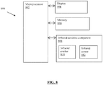
- Figure 8 shows an example handheld electronic device 800 suitable for use with an example holder of the present disclosure.
- the handheld electronic device 800 includes a microprocessor 802 for reading and executing computer-executable instructions, in order to carry out tasks and functions of the handheld electronic device 800.
- the microprocessor 802 is coupled to a display 804 for displaying output (e.g., via a graphical user interface) to a user.
- the microprocessor 802 is also coupled to a memory 806 (e.g., a read-only memory (ROM), a random-access memory (RAM), a flash memory or any other suitable memory) for storing and accessing data signals and computer-executable instructions.
- the microprocessor 802 is also coupled to an infrared-sensitive component 808, for example an infrared-sensitive navigation component, such as an optical trackpad or trackball.
- the handheld electronic device 800 is shown as including one microprocessor 802, one display 804, one memory 806 and one infrared-sensitive component 808, in some examples the handheld electronic device 800 includes more than one of any of these components.
- the handheld electronic device 800 is described as including the infrared-sensitive component 808, in some examples the infrared-sensitive component 808 is part of another component.
- the infrared emitter 810 emits infrared light and the infrared sensor 812 senses infrared light.
- the infrared-sensitive component 808 is activated when the infrared sensor 812 senses a suitable or operative infrared signal.
- An infrared signal that is sufficient to effect activation of the infrared-sensitive component 808, in some examples, is a modulated or attenuated reflection of the infrared light emitted by the infrared emitter 810.
- the activation is caused by an infrared signal that has an intensity that is within a range of operative fractions of the intensity of the emitted infrared light.
- the reflected infrared light that is sensed by the infrared sensor 812 has an intensity within 50% to 70% of the intensity of the emitted infrared light, in order to cause activation of the infrared-sensitive component 808.
- the infrared sensor 812 senses no or low level infrared signals (e.g., 10% or lower of the infrared light level emitted by the infrared emitter 810), there is no activation of the infrared-sensitive component 808.
- the infrared sensor 812 senses infrared signals near or substantially equal to the infrared light emitted by the infrared emitter 810 (e.g., at least 70%, of the infrared light emitted by the infrared emitter 810), there is no activation of the infrared-sensitive component or functionality 808.
- the handheld electronic device 800 is a wireless communication device, a portable communication device, or any other suitable handheld electronic device.
- suitable handheld electronic devices include, for example, cellular phones, mobile handhelds, digital wireless phones, 1-way pagers, 11 ⁇ 2-way pagers, 2-way pagers, electronic mail appliances, internet appliances, personal digital assistants (PDA), laptop computers, tablet computers, global positioning system (GPS) or other mapping devices, handheld games, remote controls, portable digital audio players, and the like.
- PDA personal digital assistants
- GPS global positioning system
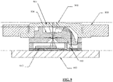
- the infrared-sensitive component includes an optical navigation device 900 that includes the infrared emitter 810 and the infrared sensor 812.
- Figure 9 shows a cross-sectional view of an example optical navigation device 900 that is included in the example infrared-sensitive component 808 of the example handheld electronic device 800.
- the example optical navigation device 900 is coupled to the casing 902 of the handheld electronic device 800.
- the optical navigation device 900 includes a navigation surface 904, a lens 906, an infrared emitter 810, and an infrared sensor 812.
- the navigation surface 904 receives touch or contact input, for example from a user's finger or other pointing means (e.g., a stylus) to direct navigation of, for example, a user interface shown on the display 804.
- a user's finger or other pointing means e.g., a stylus
- the infrared emitter 810 emits infrared light towards the navigation surface 904 and the infrared sensor 812 receives an infrared signal from the navigation surface 904.
- the lens 906 helps to focus any received infrared signal towards the infrared sensor 812.
- the infrared sensor 812 samples the received infrared signal at a relatively high rate, for example several samples per second (e.g., up to 15 samples per second).
- the optical navigation device 900 also includes other components as appropriate to process and transmit navigation signals, such as an image acquisition system, a digital signal processor and/or a communication system.
- the optical navigation device 900 is based on optical finger navigation technology. Navigation directions are sensed as changes in infrared signals at the navigation surface 904, using sequential infrared images of the navigation surface 904 to determine the direction and/or magnitude of navigation.
- the image acquisition system acquires surface images from the navigation surface 904 (which, in some examples, has a resolution in the range of several millimeters to several micrometers) via the lens 906.
- the acquired images are processed by the digital signal processor to determine direction and distance of any motion, for example by calculating the magnitude and/or rate of changes in x and y location of one or more landmarks, gradations or reference marks in the image.
- Any detected motion is transmitted (e.g., by the communication system) as a navigation signal, for example to the microprocessor 802, for further processing (e.g., as cursor navigation, scrolling or other navigation commands).
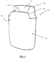
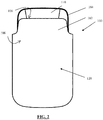
- Figures 1 and 2 show perspective and front views of an example holder 100 for a handheld electronic device, such as the device 800 of Figure 8 .
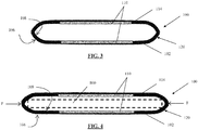
- Figures 3 and 4 show top-down views of the example holder 100 in an undeformed state ( figure 3 ) and a deformed state ( figure 4 ).
- the holder 100 includes a container 120 defining a space for receiving the handheld electronic device 800.
- the container 120 is adjustable (e.g., deformable, self-fitting, capable of being calibrated by a user or flexible so as to accommodate the handheld electronic device 800) to effect an increase or a decrease to the space.
- the container 120 includes an inner surface 108 facing inwardly towards the space.
- deformation of the container 120 e.g., at one or more deformable container portions, such as deformable side portions
- the adjustability of the container 120, to effect the increase or the decrease to the space is attributable to the deformable portion(s).
- the deformed portion(s) of the container 120 then exerts a force "F" that urges at least a portion of the deformed container 120 (e.g., side portions) against at least a portion of the received handheld electronic device 800, to effect the increase or the decrease to the space.
- F a force that urges at least a portion of the deformed container 120 (e.g., side portions) against at least a portion of the received handheld electronic device 800, to effect the increase or the decrease to the space.
- the holder 100 includes a front half 102 connected to a back half 104. In other examples (not shown), the holder 100 is formed as one integral piece, or is formed from more than two halves (e.g., including bottom and/or side portions). Regardless, components of the holder 100, individually or in cooperation with each other, form the container 120.
- the front half 102 and the back half 104 cooperate to form the container 120.
- the front half 102 and back half 104 are directly attached (e.g., with adhesive, stitching or other fastening methods).
- the front half 102 and back half 104 are indirectly attached to each other (e.g., via one or more intervening panels or components).
- the container 120 also includes an outer surface 106 that faces outwardly from the space of the container 120.
- the container 120 is shown in figure 1 as having no spaces or gaps, in some examples the container 120 includes one or more gaps, for example along side portions and/or at corner portions, which, in some examples, allows the container 120 to accommodate different sizes and types of handheld electronic devices 800.
- the deformable portion(s) of the container 120 (in this example, the side portions) is stretched width-wise to accommodate the handheld electronic device 800.
- the deformed portion(s) of the container 120 then exert(s) a force "F" on the sides of the received handheld electronic device 800.
- the deformable portion(s) of the container 120 includes a resilient material, which allow the above-described deformation and exerts the force "F” urging the deformed portion(s) of the container 120 against at least a portion of the received handheld electronic device 800.
- the holder 100 is formed from laminating layers of material together, in some examples, one or more portions of the holder 100, such as the sides of the container 120, include fewer layers, such that they are more easily deformable while still retaining at least some resiliency. In other examples, one or more portions of the holder 100 are provided with a biasing material (e.g., a shape-memory material), so as to provide the force "F".
- a biasing material e.g., a shape-memory material
- figure 4 shows the container 120 being deformed width-wise, in other examples, the container 120 is additionally or alternatively deformed depth-wise, such as where the handheld electronic device 800 has a thickness greater than the depth of the holder 100. Other types of deformation of the container 120 are also possible.
- figure 4 shows the force "F” being exerted at opposing portions of the container 120, in other examples the force "F” is exerted at only one portion of the container 120, or is exerted at more than two portions of the container 120.
- the force "F" urging at least a portion of the container 120 against at least a portion of the handheld electronic device 800 provides a friction fit or interference fit between the handheld electronic device 800 and the container 120.
- This interference fit typically is sufficient to retain the received handheld electronic device 800 within the container 120, such as against any unintentional loosening, while still allowing the handheld electronic device 800 to be manually removed from the container 120.
- At least the portion of the deformed container 120 that is urged against the handheld electronic device 800 includes and/or is lined with a material that prevents scratching, marring and/or other cosmetic damage to the handheld electronic device 800, while still ensuring contact with the handheld electronic device 800 sufficient to effect an interference fit.
- the handheld electronic device 800 includes a substantially plastic outer shell or finish.
- the inner surface 108 of the container 120 includes and/or is lined with a substantially soft or yielding material, such as a soft plastic, a soft textile or a soft leather that does not scratch, mar or otherwise damage the handheld electronic device 800, and includes a coefficient of friction with the handheld electronic device 800 sufficient to effect an interference fit with the handheld electronic device 800 received in the container 120 while still permitting manual insertion and removal of the handheld electronic device 800 from the container 120 (in some examples, acceptability of a material for permitting manual insertion of the handheld electronic device 800 is determined by subjecting the material to insertion tests).
- a substantially soft or yielding material such as a soft plastic, a soft textile or a soft leather that does not scratch, mar or otherwise damage the handheld electronic device 800
- acceptability of a material for permitting manual insertion of the handheld electronic device 800 is determined by subjecting the material to insertion tests).
- the material lining the inner surface 108 of the container 120 is any suitably soft or yielding material that acceptably cushions a handheld electronic device 800 held in the container 120 against any expected drops or other forces (in some examples, acceptability of a material is determined by subjecting the material to drop tests).
- the container 120 is formed of a relatively hard plastic material, and the inner surface 108 of the container 120 includes a soft-touch finish (e.g., a layer of coating is sprayed onto the inner surface 108, to provide a relatively soft and/or smooth surface).
- a soft-touch finish e.g., a layer of coating is sprayed onto the inner surface 108, to provide a relatively soft and/or smooth surface. This may be suitable for reducing wear on the handheld electronic device 800 and/or the inner surface 108 of the container 120 without requiring a liner.
- the use of a soft-touch finish may be suitable where the inner surface 108 is substantially planar, without protruding features or textures.
- the container 120 does not exhibit the deformation and does not effect the force "F" as described above for retaining the handheld electronic device 800.
- the holder 100 includes a strap for retaining the handheld electronic device 800 instead of relying on an interference fit.
- the holder 100 is provided with a fastener (not shown) on its outer surface 106, for fastening the holder 100 to a user or to an article of clothing.
- a suitable fastener include a clip, a belt-loop, a buckle, a hook-and-loop fastener, or any other suitable fastener.
- the fastener is a clip, the fastener is operable manually to move from a default closed position to an opened position.
- the holder 100 is provided with an adjustable strap (not shown) for effecting an increase or a decrease to the space of the container 120.
- the adjustability of the container 120 is effected by the strap.
- the strap is attached to the outer surface 106 of the back half 104 and extends over the space of the container 120, and is configured for releasable coupling to the outer surface 106 of the front half 102. The strap helps to decrease the space of the container 120 and thus retain the handheld electronic device 800 within the container 120 instead of or in addition to the interference fit described above.
- the releasable coupling is effected by interaction of a hook-and-loop fastener, a magnetic interaction between magnets provided in the strap and in the front half 102, or by releasable fasteners such as a buckle, a button or a clasp.
- the holder 100 further includes one or more magnets (not shown) on the container 120.
- the one or more magnets serve to trigger a passive mode or sleep mode of the handheld electronic device 800 when the handheld electronic device 800 is received in the container 120.
- the one or more magnets are positioned to align with a magnetic sensor on the handheld electronic device 800.
- the one or more magnets are attached to the outer surface 106, the inner surface 108, or in an inner layer between the outer surface 106 and the inner surface 108 of the container 120.
- a portion of the inner surface 108 includes an infrared-neutral material 110, i.e. an infrared absorbent material.
- the infrared-neutral material 110 is operative for preventing activation of an infrared-sensitive component of the handheld electronic device 800.
- the infrared-neutral material 110 interacts with any infrared light emitted by the handheld electronic device 800 (e.g., emitted by the infrared emitter 810) that is received by the infrared-neutral material 110.
- Such interaction includes absorption of at least a fraction of the emitted infrared light.
- the infrared-neutral material 110 absorbs at least 50% of emitted infrared light received from the handheld electronic device 800. In some examples 90% or more of the emitted infrared light from the infrared emitter 810 is absorbed, such that the infrared sensor 812 senses only 10% or less of the intensity of emitted infrared light.
- interaction includes reflection of at least a fraction of the emitted infrared light
- up to 70% or more of the emitted infrared light from the infrared emitter 810 is reflected, such that the infrared sensor 812 senses 70% or more of the intensity of emitted infrared light.
- Such interaction causes the reflected infrared signal to be other than an operative infrared signal that causes activation of the infrared-sensitive component 808.
- the interaction causes the reflected infrared signal to have an intensity that is outside the range of operative fractions (e.g., about 50% to about 70%) of the intensity of the emitted infrared light.
- figure 5 shows the infrared-neutral material 110 being provided on the front half 102 of the holder 100
- the infrared-neutral material 110 is provided on the back half 104 of the holder 100 or on both the front half 102 and the back half 104 of the holder 100 (for example, so that activation of the infrared-sensitive component is prevented regardless of which way the handheld electronic device 800 is facing when it is received in the container 120).
- the infrared-neutral material 110 is provided in other portions of the inner surface 108 of the container 120, for example where the holder 100 does not include front and back halves 102, 104.
- the infrared-neutral material 110 is positioned so as to be aligned with the infrared-sensitive component when the handheld electronic device 800 is being inserted into the container 120.
- a suitable infrared-reflecting material 110 includes any material that is substantially reflective to broad spectrum white light.
- the infrared-neutral material 110 is a substantially smooth plastic material, such as polyurethane, polyether, polypropylene, polyethylene, polycarbonate (e.g., high gloss polycarbonate), polyethylene terephthalate, acrylonitrile butadiene styrene, or a mixture of polycarbonate and acrylonitrile butadiene styrene.
- suitable materials include any material that is specifically reflective to infrared light, such as any plastic material with a high gloss surface finish.
- infrared light includes light having wavelengths within the range of, for example, about 700 nm to about 300,000 nm or greater, for example about 700 nm to about 2,500 nm, or other wavelength ranges generally recognized as being infrared light.
- the infrared-neutral material 110 is not required to be infrared-neutral for all light within the full infrared wavelength range, but is infrared-neutral only for light having wavelengths that cause activation of the infrared-sensitive component 808 of the handheld electronic device 800.
- the infrared-neutral material 110 is not required to be 100% neutral or invisible to incident infrared light, but is sufficiently infrared-neutral to prevent activation of the infrared-sensitive component or functionality 808. In some examples, instead of absorbing 100% of the emitted infrared light, the infrared-neutral material absorbs only a fraction of the emitted infrared light, sufficient to prevent activation of the infrared-sensitive component 808, as described above.
- deformation of the container 120 e.g., at one or more deformable container portions, such as deformable side portions
- the deformed portion(s) of the container 120 then exerts a force "F" that urges at least a portion of the deformed container 120 (e.g., side portions) against at least a portion of the received handheld electronic device 800.
- the deformable portion(s) of the container 120 includes a resilient material, which allow the above-described deformation and exerts the force "F” urging the deformed portion(s) of the container 120 against at least a portion of the received handheld electronic device 800.
- a resilient material which allow the above-described deformation and exerts the force "F” urging the deformed portion(s) of the container 120 against at least a portion of the received handheld electronic device 800.
- the holder 100 is formed from laminating layers of material together, in some examples, one or more portions of the holder 100, such as the sides of the container 120, include fewer layers, such that they are more easily deformable while still retaining at least some resiliency. In other examples, one or more portions of the holder 100 are provided with a biasing material (e.g., a shape-memory material), so as to provide the force "F".
- a biasing material e.g., a shape-memory material
- the force "F" urging at least a portion of the container 120 against at least a portion of the handheld electronic device 800 provides a friction fit or interference fit between the handheld electronic device 800 and the container 120.
- This interference fit typically is sufficient to retain the received handheld electronic device 800 within the container 120, such as against any unintentional loosening, while still allowing the handheld electronic device 800 to be manually removed from the container 120.
- the portion of the deformed container 120 that is urged against the handheld electronic device 800 includes and/or is lined with a material that prevents scratching, marring and/or other cosmetic damage to the handheld electronic device 800, while still ensuring contact with the handheld electronic device 800 sufficient to effect an interference fit.
- the handheld electronic device 800 includes a substantially plastic outer shell or finish.
- the container 120 includes and/or is lined with a substantially soft or yielding material, such as a soft plastic, a soft textile or a soft leather that does not scratch, mar or otherwise damage the handheld electronic device 800, but that has a coefficient of friction with the handheld electronic device 800 sufficient to effect an interference fit with the handheld electronic device 800 received in the container 120.
- Figure 6 shows a cross-section of the container 120 of an example holder 100a having the infrared-neutral material 110, i.e. the infrared absorbent material, in accordance with the first aspect.
- Figure 6 shows an example construction of the holder 100a, including a plurality of layers laminated together.
- the front half 102 and the back half 104 are substantially similar in construction, although in other examples the construction is different between the front half 102 and the back half 104.
- the layers of the container 120 include an outermost layer 602, an outer stiffening layer 604, an inner stiffening layer 606, a reinforcement layer 608, and a liner 610, in addition to the infrared-neutral material 110.
- an outermost layer 602 an outer stiffening layer 604
- an inner stiffening layer 606 an inner stiffening layer 606
- a reinforcement layer 608 a reinforcement layer 608
- a liner 610 in addition to the infrared-neutral material 110.
- one or more of these layers are omitted and/or one or more layers are added.
- the outermost layer 602 is a flexible layer, such as a plastic (e.g., polyurethane, polyether, polypropylene, polyethylene, polyethylene terephthalate, polycarbonate (e.g., high gloss polycarbonate), acrylonitrile butadiene styrene, a mixture of polycarbonate and acrylonitrile butadiene styrene or other suitable plastic), a textile or leather, for example.
- the outermost layer 602 provides the outer surface 106 of the container 120, and is selected to have a pleasing aesthetic effect.
- the outermost layer 602 has a thickness of about 0.5 mm to about 1.0 mm.
- the outermost layer 602 is a polyurethane material that is about 0.8 mm thick.
- the outer stiffening layer 604 is provided to help increase the stiffness or rigidity of the container 120.
- the outermost layer 602 is made of a suitably stiff material (e.g., a suitably thick polypropylene material)
- the outer stiffening layer 604 is not required.
- the outer stiffening layer 604 is provided over substantially all portions of the container 120.
- the outer stiffening layer 604 helps to increase the rigidity of the container 120, the outer stiffening layer 604 is still be sufficiently flexible and resilient so as to permit the deformation of the container 120 when the handheld electronic device 800 is received therein, and to effect the force "F" urging the container 120 against the handheld electronic device 800 when the container 120 is deformed.
- the outer stiffening layer 604 is made of any suitable material including, for example, a plastic (e.g., polypropylene or polyether), a textile (e.g., a soft vulcanized fiber), a metal (e.g., a thin shape-memory alloy), or any other suitable material.
- a plastic e.g., polypropylene or polyether
- a textile e.g., a soft vulcanized fiber
- a metal e.g., a thin shape-memory alloy
- the outer stiffening layer 604 has a thickness of about 0.5 mm to about 1.0 mm.
- the outer stiffening layer 604 is a soft vulcanized fiber material that is about 0.6 mm thick.
- the inner stiffening material 606 is provided to further increase the rigidity of the container 120, and is provided only in select portions of the container 120. In some examples, the absence of the inner stiffening material 606 in one or more portions of the container 120 provides one or more corresponding deformable portions of the container 120. In examples where the container 120 is designed to include deformable side portions (e.g., allowing the container 120 to deform width-wise), the inner stiffening material 606 is absent in the side portions of the container 120.
- the inner stiffening material 606 is made of any suitable material including, for example, a plastic (e.g., polypropylene or polyether), a textile (e.g., a vulcanized fiber), a metal (e.g., a thin shape-memory alloy), or any other suitable material.
- a plastic e.g., polypropylene or polyether
- a textile e.g., a vulcanized fiber
- a metal e.g., a thin shape-memory alloy
- the inner stiffening material 606 has a thickness of about 0.5 mm to about 1.5 mm.
- the inner stiffening material 606 is a vulcanized fiber material that is about 1.0 mm thick.
- the reinforcement material 608 is provided to further increase the rigidity of the container 120, and is absent from one or more deformable portions of the container 120.
- the reinforcement material 608 is absent in the side portions of the container 120.
- the reinforcement material 608 serves to reinforce a joint in the container 120 where the infrared-neutral material 110 is provided.
- the reinforcement material 608 includes a notch or recess to help create a substantially continuous level surface on either side of the infrared-neutral material 110.
- the reinforcement material 608 is made of any suitable material including, for example, a plastic (e.g., polypropylene or polyether), a textile (e.g., a vulcanized fiber), a metal (e.g., a thin shape-memory alloy), or any other suitable material.
- the reinforcement material 608 has a thickness of about 0.5 mm to about 2.0 mm.
- the reinforcement material 608 is a vulcanized fiber material that is about 1.2 mm thick.
- the liner 610 provides the inner surface 108 of the container 120, with the exception of any portions having the infrared-neutral material 110.
- the infrared-neutral material is provided over the liner 610 on the inner surface 108 in one or more portions of the container 120.
- the liner 610 is selected to have a pleasing aesthetic effect.
- the liner 610 is a flexible layer, such as a plastic (e.g., polyurethane, polyether, polypropylene, polyethylene, polyethylene terephthalate, polycarbonate (e.g., high gloss polycarbonate), acrylonitrile butadiene styrene, a mixture of polycarbonate and acrylonitrile butadiene styrene or other suitable plastic), a textile (e.g., a felt material or a fiber material) or leather, for example.
- the liner 610 is made of a material selected to avoid scratching or marring of the handheld electronic device 800.
- the liner 610 is made of a material that is substantially softer and/or more yielding than the outer shell or outer finish of the handheld electronic device 800.
- the liner 610 is also made of a material designed to have a coefficient of friction with the handheld electronic device 800 sufficient to effect an interference fit when the handheld electronic device 800 is received in the container 120.
- the liner 610 has a thickness of about 0.1 mm to about 1.0 mm.
- the liner is a peach fiber material that is about 0.3 mm thick.
- the infrared-neutral material 110 includes a substantially smooth material (e.g., a plastic material, such as a plastic material having a high gloss surface finish) that serves to reflect a sufficient amount of incident infrared light emitted from the handheld electronic device 800 (e.g., at least 50% or at least 70% of infrared light emitted from the infrared emitter 810), to prevent activation of the infrared-sensitive component 808 of the handheld electronic device 800.
- the infrared-neutral material 110 includes a substantially smooth, reflective plastic material, such as high-gloss polyurethane.
- the infrared-neutral material 110 has a thickness of about 0.1 mm to about 1.5 mm, for example about 0.6 mm.
- the infrared-neutral material 110 is integrally formed or bonded (e.g., thermally bonded) to one or more layers, such as the liner 610.
- the infrared-neutral material 110 includes infrared-absorbing components and the infrared-neutral material 110 serves to absorb a sufficient amount of incident infrared light (e.g., at least 50% or at least 90% of infrared light emitted from the infrared emitter 810), to prevent activation of the infrared-sensitive component 808 of the handheld electronic device 800.
- outermost layer 602, outer stiffening layer 604, inner stiffening layer 606, reinforcement layer 608, liner 610, and infrared-neutral material 110 have been described has having certain thicknesses, other thickness values are possible.
- the thickness of each of the outermost layer 602, outer stiffening layer 604, inner stiffening layer 606, reinforcement layer 608, liner 610, and infrared-neutral material 110 may vary depending on the material used as well as the method for processing the material.
- a portion of the inner surface 108 includes an infrared-neutral coating, i.e. an infrared absorbent coating.
- the infrared-neutral coating interacts with emitted infrared light received by the infrared-neutral coating from the handheld electronic device 800 (e.g., emitted by the infrared emitter 810) such that, while the handheld electronic device 800 is being received by the container 120, the resulting reflected infrared signal is inoperative to effect activation of the infrared-sensitive component 808 of the handheld electronic device 800.
- the interaction with the emitted infrared light results in a reflected infrared signal that is inoperative to effect activation of the infrared-sensitive component or functionality 808 when the reflected infrared signal is sensed by the handheld electronic device (e.g., sensed by the infrared sensor 812).
- Such interaction includes absorption of at least a fraction of the emitted infrared light.
- the infrared-neutral coating absorbs at least 50% of emitted infrared light received from the handheld electronic device 800. In some examples 90% or more of the emitted infrared light from the infrared emitter 810 is absorbed, such that the infrared sensor 812 senses only 10% or less of the intensity of emitted infrared light.
- interaction includes reflection of at least a fraction of the emitted infrared light
- up to 70% or more of the emitted infrared light from the infrared emitter 810 is reflected, such that the infrared sensor 812 senses 70% or more of the intensity of emitted infrared light.
- Such interaction causes the reflected infrared signal to be other than an operative infrared signal that causes activation of the infrared-sensitive component 808.
- the interaction causes the reflected infrared signal to have an intensity that is outside the range of operative fractions (e.g., about 50% to about 70%) of the intensity of the emitted infrared light.
- the infrared-neutral coating in examples not according to the invention, is included on the entire inner surface 108. In other examples, the infrared-neutral coating is included only on a portion of the inner surface 108. In accordance with the invention, the infrared-neutral coating is included only on portion(s) of the inner surface 108 aligned with the infrared-sensitive component when the handheld electronic device 800 is being inserted into the container 120. In some examples, the infrared-neutral coating is included on at least a portion of the inner surface 108 corresponding only to the front half 102 of the holder 100, or corresponding onto to the back half 104 of the holder 100.
- the infrared-neutral coating is included on portions of the inner surface 108 corresponding to both the front half 102 and the back half 104 of the holder 100 (for example, so that activation of the infrared-sensitive component is prevented regardless of which way the handheld electronic device 800 is facing when it is received in the container 120).
- the infrared-neutral coating is any suitable paint or coating that prevents activation of the infrared-sensitive component of the handheld electronic device.
- the infrared-neutral coating is infrared-absorbing.
- a suitable infrared-neutral coating examples include infrared-absorbent constituents such as: thin film metals (including, for example, copper, gold, nickel, silver, and combinations thereof), metal oxides (including, for example, hafnium oxide, indium tin oxide, magnesium oxide, silicon monoxide, titanium dioxide, tantalum oxide, zirconium oxide, and combinations thereof), nickel manganese ferrite, iron chromite, cadmium stannate, organic compounds (including, for example, chlorophyll), and combinations thereof.
- the infrared-neutral coating is any suitable infrared-invisible paint, such as those used for camouflage or stealth purposes.
- the infrared-neutral coating is an infrared-reflective paint or coating, including paints and/or pigments developed for heat-reflection purposes, such as the Arctic® pigments developed by Shepherd Color Company, the InsultecTM head reflective paints, the ZEFFLETM infrared reflective coatings, and other suitable paints or coatings.
- the infrared-neutral coating is an infrared-absorbing paint or coating, including paints and/or pigments such as the VancevaTM coating developed by Solutia and Sumitomo Metal Mining.
- infrared light includes light having wavelengths within the range of, for example, about 700 nm to about 300,000 nm or greater, for example about 700 nm to about 2,500 nm, or other wavelength ranges generally recognized as being infrared light.
- the infrared-neutral coating is not required to be infrared-neutral for all light within the full infrared wavelength range, but is infrared-neutral only for light having wavelengths that causes activation of the infrared-sensitive component 808 of the handheld electronic device 800.
- the infrared-neutral coating is not required to be 100% neutral or invisible to incident infrared light, but is sufficiently infrared-neutral to prevent activation of the infrared-sensitive component or functionality 808.
- the infrared-neutral material instead of absorbing 100% of the emitted infrared light, absorbs only a fraction of the emitted infrared light, i.e. at least 50%, sufficient to prevent activation of the infrared-sensitive component 808, as described above.
- Figure 7 shows a cross-section of the container 120 of an example holder 100b having an infrared-neutral coating 612, in accordance with the second aspect.
- the example holder 110b includes a container 120 having an outermost layer 602, an outer stiffening layer 604, an inner stiffening layer 606, a reinforcement layer 608 and a liner 610.
- one or more of these layers are omitted and/or one or more layers are added.
- the outermost layer 602 is a flexible layer, such as a plastic (e.g., polyurethane, polyether, polypropylene, polyethylene, polyethylene terephthalate, polycarbonate (e.g., high gloss polycarbonate), acrylonitrile butadiene styrene, a mixture of polycarbonate and acrylonitrile butadiene styrene or other suitable plastic), a textile or leather, for example.
- the outermost layer 602 provides the outer surface 106 of the container 120, and is selected to have a pleasing aesthetic effect.
- the outermost layer 602 has a thickness of about 0.5 mm to about 1.0 mm.
- the outermost layer 602 is a polyurethane material that is about 0.8 mm thick.
- the outer stiffening layer 604 is provided to help increase the stiffness or rigidity of the container 120.
- the outermost layer 602 is made of a suitably stiff material (e.g., a suitably thick polypropylene material)
- the outer stiffening layer 604 is not required.
- the outer stiffening layer 604 is provided over substantially all portions of the container 120.
- the outer stiffening layer 604 is made of any suitable material including, for example, a plastic (e.g., polypropylene or polyether), a textile (e.g., a soft vulcanized fiber), a metal (e.g., a thin shape-memory alloy), or any other suitable material.
- the outer stiffening layer 604 has a thickness of about 0.5 mm to about 1.0 mm.
- the outer stiffening layer 604 is a soft vulcanized fiber material that is about 0.6 mm thick.
- the inner stiffening material 606 is provided to further increase the rigidity of the container 120, and is provided only in select portions of the container 120.
- the container 120 includes deformable portion(s)
- the absence of the inner stiffening material 606 in one or more portions of the container 120 provides one or more corresponding deformable portions of the container 120.
- the container 120 is designed to include deformable side portions (e.g., allowing the container 120 to deform width-wise)
- the inner stiffening material 606 is absent in the side portions of the container 120.
- the inner stiffening material 606 is made of any suitable material including, for example, a plastic (e.g., polypropylene or polyether), a textile (e.g., a vulcanized fiber), a metal (e.g., a thin shape-memory alloy), or any other suitable material.
- a plastic e.g., polypropylene or polyether
- a textile e.g., a vulcanized fiber
- a metal e.g., a thin shape-memory alloy
- the inner stiffening material 606 has a thickness of about 0.5 mm to about 1.5 mm.
- the inner stiffening material 606 is a vulcanized fiber material that is about 1.0 mm thick.
- the reinforcement material 608 is provided to further increase the rigidity of the container 120.
- the reinforcement material 608 is absent from one or more deformable portions of the container 120.
- the reinforcement material 608 is made of any suitable material including, for example, a plastic (e.g., polypropylene or polyether), a textile (e.g., a vulcanized fiber), a metal (e.g., a thin shape-memory alloy), or any other suitable material.
- the reinforcement material 608 has a thickness of about 0.5 mm to about 2.0 mm.
- the reinforcement material 608 is a vulcanized fiber material that is about 1.2 mm thick.
- the liner 610 provides the inner surface 108 of the container 120.
- the liner 610 is selected to have a pleasing aesthetic effect.
- the liner 610 is a flexible layer, such as a plastic (e.g., polyurethane, polyether, polypropylene, polyethylene, polyethylene terephthalate or other suitable plastic), a textile (e.g., a felt material or a fiber material) or leather, for example.
- the liner 610 is made of a material selected to avoid scratching or marring of the handheld electronic device 800.
- the liner 610 is made of a material that is substantially softer and/or more yielding than the outer shell or outer finish of the handheld electronic device 800.
- the liner 610 is also made of a material designed to have a coefficient of friction with the handheld electronic device 800 sufficient to effect an interference fit when the handheld electronic device 800 is received in the container 120.
- the liner 610 has a thickness of about 0.1 mm to about 1.0 mm.
- the liner is a peach fiber material that is about 0.3 mm thick.
- the example holder 110b includes the infrared-neutral coating 612 on a portion of its inner surface 108.
- the infrared-neutral coating 612 in this example, is provided on a substrate such as the liner 610.
- the example holder 110b is shown with a reinforcement layer 608, in some examples the reinforcement layer 608 is not needed.
- the infrared-neutral coating 612 is sufficiently thin such that there is no unevenness caused by its application over the liner 610.
- the infrared-neutral coating 612 is already provided on the liner 610 (e.g., precoated on the liner 610 or pre-embedded in the liner 610) rather than as a separate coating applied during manufacturing.
- outermost layer 602, outer stiffening layer 604, inner stiffening layer 606, reinforcement layer 608, and liner 610 have been described has having certain thicknesses, other thickness values are possible.
- the thickness of each of the outermost layer 602, outer stiffening layer 604, inner stiffening layer 606, reinforcement layer 608, and liner 610 may vary depending on the material used as well as the method for processing the material.
- the inner surface 108 of the container 120 includes opposing inner surface side portions defined by a substantially non-abrasive material.
- the substantially non-abrasive material is non-abrasive or substantially non-abrasive relative to the handheld electronic device 800 while the handheld electronic device 800 is being received by the container 120.
- the substantially non-abrasive material is material that is softer than any plastic used for the outer surface of the handheld electronic device 800.
- the non-abrasiveness or substantially non-abrasiveness of the inner surface 108 includes non-abrasiveness or substantially non-abrasiveness exhibited by the substantially non-abrasive material relative to side surface portions of the handheld electronic device 800, while the handheld electronic device 800 is being received by the container.
- the side surface portions of the handheld electronic device 800 are defined by plastic material, and the substantially non-abrasive material is non-abrasive or substantially non-abrasive relative to the plastic material.
- the substantially non-abrasive material is material that is softer than polyurethane. In some embodiments, for example, the substantially non-abrasive material is characterized by a hardness value that is less than the hardness of the outer surface of the handheld electronic device 800. In some examples, the substantially non-abrasive material has a hardness of less than 2.0 on the Mohs hardness scale, for example less than 1.0 on the Mohs hardness scale. In some examples, the substantially non-abrasive material is any material that is determined to be non-abrasive through imperial testing, such as by repeatedly subjecting the material to the outer surface of the handheld electronic device 800 and observing whether there is any damage to the outer surface of the handheld electronic device 800. Abrasive damage includes any mechanical damage that removes material from a surface, including, for example, scratching, scuffing, marring, wearing down or rubbing away of a surface.
- a portion of the inner surface 108 includes an infrared-neutral material 110 operative for interacting with infrared light emitted from the handheld electronic device 800 and received by the infrared-neutral material 110.
- the interaction is such that, while the handheld electronic device 800 is being received by the container 120, any reflected infrared signal effected by the interaction is inoperative for effecting activation of a functionality of the handheld electronic device 800 when the reflected infrared signal is sensed by the handheld electronic device 800.
- the infrared-neutral material 110 is operative for preventing activation of the infrared-sensitive component 808 of the handheld electronic device 800.
- the infrared-neutral material 110 interacts with any infrared light emitted by the handheld electronic device 800 (e.g., emitted by the infrared emitter 810) that is received by the infrared-neutral material 110.
- Such interaction includes absorption of at least a fraction of the emitted infrared light.
- the infrared-neutral material 110 absorbs at least 50% of emitted infrared light received from the handheld electronic device 800. In some examples 90% or more of the emitted infrared light from the infrared emitter 810 is absorbed, such that the infrared sensor 812 senses only 10% or less of the intensity of emitted infrared light.
- interaction includes reflection of at least a fraction of the emitted infrared light
- up to 70% or more of the emitted infrared light from the infrared emitter 810 is reflected, such that the infrared sensor 812 senses 70% or more of the intensity of emitted infrared light.
- Such interaction causes the reflected infrared signal to be other than an operative infrared signal that causes activation of the infrared-sensitive component 808.
- the interaction causes the reflected infrared signal to have an intensity that is outside the range of operative fractions (e.g., about 50% to about 70%) of the intensity of the emitted infrared light.
- the infrared-neutral material 110 is provided on the front half 102 of the holder 100, in other examples the infrared-neutral material 110 is provided on the back half 104 of the holder 100 or on both the front half 102 and the back half 104 of the holder 100 (for example, so that activation of the infrared-sensitive component is prevented regardless of which way the handheld electronic device 800 is facing when it is received in the container 120).
- the infrared-neutral material 110 is provided in other portions of the inner surface 108 of the container 120, for example where the holder 100 does not include front and back halves 102, 104. The infrared-neutral material 110 is positioned so as to be aligned with the infrared-sensitive component when the handheld electronic device 800 is being inserted into the container 120.
- a suitable infrared-reflecting material 110 includes any material that is substantially reflective to broad spectrum white light.
- the infrared-neutral material 110 is a substantially smooth plastic material (including plastic materials with a high gloss surface finish), such as polyurethane, polyether, polypropylene, polyethylene, polyethylene terephthalate, polycarbonate (e.g., high gloss polycarbonate), acrylonitrile butadiene styrene, or a mixture of polycarbonate and acrylonitrile butadiene styrene.
- suitable materials include any material that is specifically reflective to infrared light.
- infrared light includes light having wavelengths within the range of, for example, about 700 nm to about 300,000 nm or greater, for example about 700 nm to about 2,500 nm, or other wavelength ranges generally recognized as being infrared light.
- the infrared-neutral material 110 is not required to be infrared-neutral for all light within the full infrared wavelength range, but is infrared-neutral only for light having wavelengths that cause activation of the infrared-sensitive component 808 of the handheld electronic device 800.
- the infrared-neutral material 110 is not required to be 100% neutral or invisible to incident infrared light, but is sufficiently infrared-neutral to prevent activation of the infrared-sensitive component or functionality 808. In some examples, instead of absorbing 100% of the emitted infrared light, the infrared-neutral material absorbs only a fraction of the emitted infrared light, sufficient to prevent activation of the infrared-sensitive component 808, as described above.
- the infrared-neutral material 110 includes an infrared-neutral coating.
- the infrared-neutral coating is any suitable paint or coating that prevents activation of the infrared-sensitive component of the handheld electronic device 800.
- the infrared-neutral coating is infrared-absorbing and in other examples, not according to the invention, the infrared-neutral coating is infrared-reflecting.
- a suitable infrared-neutral coating examples include infrared-absorbent constituents such as: thin film metals (including, for example, copper, gold, nickel, silver, and combinations thereof), metal oxides (including, for example, hafnium oxide, indium tin oxide, magnesium oxide, silicon monoxide, titanium dioxide, tantalum oxide, zirconium oxide, and combinations thereof), nickel manganese ferrite, iron chromite, cadmium stannate, organic compounds (including, for example, chlorophyll), and combinations thereof.
- the infrared-neutral coating is any suitable infrared-invisible paint, such as those used for camouflage or stealth purposes.
- the infrared-neutral coating is an infrared-reflective paint or coating, including paints and/or pigments developed for heat-reflection purposes, such as the Arctic® pigments developed by Shepherd Color Company, the InsultecTM head reflective paints, the ZEFFLETM infrared reflective coatings, and other suitable paints or coatings.
- the infrared-neutral coating is an infrared-absorbing paint or coating, including paints and/or pigments such as the VancevaTM coating developed by Solutia and Sumitomo Metal Mining.
- the infrared-neutral coating is applied to a substrate (e.g., the lining 610) that is incorporated within the holder 100. In some examples, the infrared-neutral coating is applied to the substrate before the substrate is incorporated within the holder 100.
- a holder for a handheld electronic device which are suitable for one or more of the example holders 100, 100a, 100b described above.
- a method of manufacturing the holder 100, 100a, 100b includes laminating a plurality of layers (e.g., the layers 602, 604, 606, 608 and 610 described above, and including the infrared-neutral material 110 where appropriate) together to form a composite material.
- the layers are pre-cut into the desired shape. In other examples, the layers are cut after lamination. The composite material is then formed into the desired shape and fastened together to form the container 120.
- the method of manufacturing the holder 100, 100a, 100b includes:
- the example method includes additional features and further processing.
- a fastener, a strap and/or a magnet are added to the holder 100, 100a, 100b.
Landscapes
- Engineering & Computer Science (AREA)
- Theoretical Computer Science (AREA)
- General Engineering & Computer Science (AREA)
- Human Computer Interaction (AREA)
- Physics & Mathematics (AREA)
- General Physics & Mathematics (AREA)
- Computer Hardware Design (AREA)
- Purses, Travelling Bags, Baskets, Or Suitcases (AREA)
- Telephone Set Structure (AREA)
Claims (14)
- Ein System, das aufweist:eine handgehaltene elektronische Vorrichtung (800), undeine Haltevorrichtung (100, 100a) für die handgehaltene elektronische Vorrichtung (800), wobei die Haltevorrichtung (100, 100a) aufweist:einen Behälter (120), der einen Raum zur Aufnahme der handgehaltenen elektronischen Vorrichtung (800) definiert, wobei der Behälter (120) eine innere Oberfläche (108) umfasst, die nach innen dem Raum zugewandt ist, wobei der Behälter anpassbar ist, um eine Zunahme oder eine Abnahme des Raums zu bewirken;ein Material (110), das an der inneren Oberfläche (108) vorgesehen ist, wobei das Material (110) interaktiv mit Infrarotlicht ist, das von der handgehaltenen elektronischen Vorrichtung (800) emittiert wird und von dem Material (110) empfangen wird, wobei das Material nur an einem Teil der inneren Oberfläche (108) vorgesehen ist und positioniert ist, um mit einer Infrarot-empfindlichen Komponente (900) der handgehaltenen elektronischen Vorrichtung (800) ausgerichtet zu werden, wenn die handgehaltene elektronische Vorrichtung (800) in den Behälter (120) eingeführt wird, und wobei das Material (110) zumindest 50% des Infrarotlichts absorbiert, das von der handgehaltenen elektronischen Vorrichtung (800) emittiert wird, wodurch das Material (110) betriebsfähig ist zum Verhindern einer unbeabsichtigten Aktivierung der Infrarot-empfindlichen Komponente (900).
- Das System gemäß Anspruch 1, wobei, wenn die handgehaltene elektronische Vorrichtung (800) in dem Behälter (120) aufgenommen ist, eine Verformung von zumindest einem verformbaren Behälterteil bewirkt wird, um zumindest einen verformten Behälterteil vorzusehen, der eine Kraft ausübt, die den zumindest einen verformten Behälterteil gegen zumindest einen Teil der aufgenommenen handgehaltenen elektronischen Vorrichtung (800) drückt, um die Zunahme oder die Abnahme des Raums zu bewirken derart, dass die Anpassbarkeit des Behälters (120) zumindest teilweise auf den zumindest einen verformbaren Teil zurückführbar ist.
- Das System gemäß Anspruch 1, wobei das Material (110) betriebsfähig ist zum Absorbieren von zumindest 90% des emittierten Infrarotlichts.
- Das System gemäß Anspruch 1, wobei die Funktionalität eine Navigationsfunktion umfasst.
- Das System gemäß Anspruch 1, das weiter ein Befestigungselement aufweist zum lösbaren Befestigen der Haltevorrichtung (100, 100a) an einem Benutzer.
- Ein System, das aufweist:eine handgehaltene elektronische Vorrichtung (800), undeine Haltevorrichtung (100, 100b) für die handgehaltene elektronische Vorrichtung (800), wobei die Haltevorrichtung (100, 100b) aufweist:einen Behälter (120), der einen Raum zur Aufnahme der handgehaltenen elektronischen Vorrichtung (800) definiert, wobei der Behälter (120) eine innere Oberfläche (108) umfasst, die nach innen dem Raum zugewandt ist;eine Beschichtung (612), die zumindest einen Teil der inneren Oberfläche (108) definiert, wobei die Beschichtung (612) interaktiv mit Infrarotlicht ist, das von der handgehaltenen elektronischen Vorrichtung (800) emittiert wird und von der Beschichtung (612) empfangen wird, wobei die Beschichtung nur auf einem Teil der inneren Oberfläche (108) vorgesehen ist, der mit einer Infrarot-empfindlichen Komponente (900) der handgehaltenen elektronischen Vorrichtung (800) ausgerichtet ist, wenn die handgehaltene elektronische Vorrichtung (800) in den Behälter (120) eingeführt wird, und wobei die Beschichtung (612) zumindest 50% des Infrarotlichts absorbiert, das von der handgehaltenen elektronischen Vorrichtung (800) emittiert wird, wodurch die Beschichtung (612) betriebsfähig ist zum Verhindern einer unbeabsichtigten Aktivierung der Infrarot-empfindlichen Komponente (900).
- Das System gemäß Anspruch 6, wobei die Beschichtung (612) betriebsfähig ist zum Absorbieren von zumindest 90% des emittierten Infrarotlichts.
- Das System gemäß Anspruch 6, wobei die Funktionalität eine Navigationsfunktion umfasst.
- Das System gemäß Anspruch 6, wobei, wenn die handgehaltene elektronische Vorrichtung (800) in dem Behälter (120) aufgenommen ist, eine Verformung von zumindest einem verformbaren Behälterteil bewirkt wird, um zumindest einen verformten Behälterteil vorzusehen, der eine Kraft ausübt, die den zumindest einen verformten Behälterteil gegen zumindest einen Teil der aufgenommenen handgehaltenen elektronischen Vorrichtung (800) drückt, um eine Zunahme oder eine Abnahme des Raums zu bewirken.
- Ein System, das aufweist:eine handgehaltene elektronische Vorrichtung (800), undeine Haltevorrichtung (100) für die handgehaltene elektronische Vorrichtung (800), wobei die Haltevorrichtung (100) aufweist:einen Behälter (120), der einen Raum zur Aufnahme der handgehaltenen elektronischen Vorrichtung (800) definiert, wobei der Behälter (120) eine innere Oberfläche (108) umfasst, die nach innen dem Raum zugewandt ist;wobei die innere Oberfläche (108) gegenüberliegende InnenflächenSeitenteile umfasst, die durch ein im Wesentlichen nicht-abrasives Material definiert sind, wobei das im Wesentlichen nicht-abrasive Material in Bezug auf die handgehaltene elektronische Vorrichtung (800) nicht-abrasiv oder im Wesentlichen nicht-abrasiv ist, während die handgehaltene elektronische Vorrichtung (800) durch den Behälter (120) aufgenommen ist;ein Material (110), das an der inneren Oberfläche (108) vorgesehen ist, wobei das Material (110) interaktiv mit Infrarotlicht ist, das von der handgehaltenen elektronischen Vorrichtung (800) emittiert wird und von dem Material (110) empfangen wird, wobei das Material nur an einem Teil der inneren Oberfläche (108) vorgesehen ist und positioniert ist, um mit einer Infrarot-empfindlichen Komponente (900) der handgehaltenen elektronischen Vorrichtung (800) ausgerichtet zu werden, wenn die handgehaltene elektronische Vorrichtung (800) in den Behälter (120) eingeführt wird, und wobei das Material (110) zumindest 50% des Infrarotlichts absorbiert, das von der handgehaltenen elektronischen Vorrichtung (800) emittiert wird, wodurch das Material (110) betriebsfähig ist zum Verhindern einer unbeabsichtigten Aktivierung einer Infrarot-empfindlichen Komponente (900).
- Das System gemäß Anspruch 10, wobei, wenn die handgehaltene elektronische Vorrichtung (800) in dem Behälter (120) aufgenommen ist, eine Verformung von zumindest einem verformbaren Behälterteil bewirkt wird, um zumindest einen verformten Behälterteil vorzusehen, der eine Kraft ausübt, die den zumindest einen verformten Behälterteil gegen zumindest einen Teil der aufgenommenen handgehaltenen elektronischen Vorrichtung (800) drückt, um eine Zunahme oder eine Abnahme des Raums zu bewirken.
- Das System gemäß Anspruch 10, wobei das Material (110) betriebsfähig ist zum Absorbieren von zumindest 90% des emittierten Infrarotlichts.
- Das System gemäß Anspruch 10, wobei die Funktionalität eine Navigationsfunktion umfasst.
- Das System gemäß Anspruch 6 oder 10, das weiter ein Befestigungselement aufweist zum lösbaren Befestigen der Haltevorrichtung (100) an einem Benutzer.
Applications Claiming Priority (1)
| Application Number | Priority Date | Filing Date | Title |
|---|---|---|---|
| US201161435378P | 2011-01-24 | 2011-01-24 |
Publications (2)
| Publication Number | Publication Date |
|---|---|
| EP2478792A1 EP2478792A1 (de) | 2012-07-25 |
| EP2478792B1 true EP2478792B1 (de) | 2016-12-21 |
Family
ID=44772855
Family Applications (1)
| Application Number | Title | Priority Date | Filing Date |
|---|---|---|---|
| EP11183635.9A Active EP2478792B1 (de) | 2011-01-24 | 2011-09-30 | System umfassend eine tragbare elektronische Vorrichtung und einen Halter |
Country Status (4)
| Country | Link |
|---|---|
| US (2) | US8827129B2 (de) |
| EP (1) | EP2478792B1 (de) |
| CN (1) | CN102711396A (de) |
| CA (1) | CA2764854C (de) |
Families Citing this family (7)
| Publication number | Priority date | Publication date | Assignee | Title |
|---|---|---|---|---|
| WO2013043462A1 (en) | 2011-09-19 | 2013-03-28 | Speculative Product Design, Llc | Case for a portable electronic device with over-molded thermo-formed film |
| US12565022B2 (en) * | 2016-11-21 | 2026-03-03 | eXClaim IP, LLC | Insulative material |
| US11254091B2 (en) * | 2016-11-21 | 2022-02-22 | eXCIaim IP, LLC | Protective thermal sleeve for portable electronic devices and pharmaceuticals |
| US10505307B2 (en) | 2017-03-30 | 2019-12-10 | Microsoft Technology Licensing, Llc | Plastic-lined interconnect receptacle |
| US10630832B1 (en) * | 2017-11-17 | 2020-04-21 | Charles Isgar | Smartphone lock box system |
| US10937001B1 (en) | 2017-11-17 | 2021-03-02 | Charles Isgar | Smartphone lock box system |
| IT201800009212A1 (it) * | 2018-10-05 | 2020-04-05 | Gadi D'urbino | Custodia da tasca atta a coprire e proteggere le principali interfacce del telefono cellulare in essa riposto e a schermare le onde elettromagnetiche emesse dal telefono in direzione del corpo umano |
Citations (1)
| Publication number | Priority date | Publication date | Assignee | Title |
|---|---|---|---|---|
| US20020175099A1 (en) * | 2001-05-22 | 2002-11-28 | Wu Ko Lee | Cellular telephone bag |
Family Cites Families (13)
| Publication number | Priority date | Publication date | Assignee | Title |
|---|---|---|---|---|
| US6367672B1 (en) * | 2000-04-03 | 2002-04-09 | Sur Grip Holsters, Limited | Cellular/portable phone holder |
| US6772881B2 (en) * | 2002-07-29 | 2004-08-10 | Scott C. Le | Remote control cover |
| WO2004092037A1 (en) * | 2003-04-14 | 2004-10-28 | Cpfilms Inc. | Sealed container for temporarily inactivating a cell phone |
| GB2404819A (en) | 2003-08-05 | 2005-02-09 | Research In Motion Ltd | Mobile communications device with integral optical navigation |
| US20050092504A1 (en) | 2003-11-03 | 2005-05-05 | Walthall Lacy M. | Personal electromagnetic security unit and method for electromagnetically shielding portable electronic communication and data devices and the like |
| US20050255898A1 (en) * | 2004-03-31 | 2005-11-17 | Neotrends Products, Inc. | Cell phone and holder |
| US20060226039A1 (en) | 2005-03-29 | 2006-10-12 | A.G. Findings & Mfg. Co., Inc. | Holster for cell phone or device with molded acoustic vents |
| US20060226777A1 (en) * | 2005-04-07 | 2006-10-12 | Cunningham David W | Incandescent lamp incorporating extended high-reflectivity IR coating and lighting fixture incorporating such an incandescent lamp |
| US7428427B2 (en) | 2005-11-02 | 2008-09-23 | Sony Ericsson Mobile Communications Ab | IMF cover for a portable electronic device |
| US20080032758A1 (en) | 2006-08-02 | 2008-02-07 | Ramin Rostami | Handheld device protective case |
| DE102007010657A1 (de) | 2007-03-02 | 2008-09-04 | Ali Jaseb | Tasche für ein Mobilfunkgerät |
| FR2915055A1 (fr) | 2007-04-12 | 2008-10-17 | Lim Meang Sor | Pochette anti-radiations |
| EP2073103A1 (de) | 2007-12-19 | 2009-06-24 | Research In Motion Limited | Eingabemechanismus für ein elektronisches Kommunikationshandgerät |
-
2011
- 2011-09-30 EP EP11183635.9A patent/EP2478792B1/de active Active
- 2011-09-30 US US13/249,610 patent/US8827129B2/en active Active
-
2012
- 2012-01-19 CN CN2012100177765A patent/CN102711396A/zh active Pending
- 2012-01-19 CA CA2764854A patent/CA2764854C/en active Active
-
2014
- 2014-08-06 US US14/452,699 patent/US9004334B2/en active Active
Patent Citations (1)
| Publication number | Priority date | Publication date | Assignee | Title |
|---|---|---|---|---|
| US20020175099A1 (en) * | 2001-05-22 | 2002-11-28 | Wu Ko Lee | Cellular telephone bag |
Also Published As
| Publication number | Publication date |
|---|---|
| US20120255977A1 (en) | 2012-10-11 |
| EP2478792A1 (de) | 2012-07-25 |
| US8827129B2 (en) | 2014-09-09 |
| CN102711396A (zh) | 2012-10-03 |
| CA2764854A1 (en) | 2012-07-24 |
| US20140340844A1 (en) | 2014-11-20 |
| US9004334B2 (en) | 2015-04-14 |
| CA2764854C (en) | 2015-12-01 |
Similar Documents
| Publication | Publication Date | Title |
|---|---|---|
| EP2478792B1 (de) | System umfassend eine tragbare elektronische Vorrichtung und einen Halter | |
| US8960421B1 (en) | Foldable front cover for electronic tablet | |
| US8312991B2 (en) | Case for electronic tablet | |
| US8757376B2 (en) | Protective covering for personal electronic device | |
| US9056696B1 (en) | Portfolio with integrated computer and accessory pockets | |
| US9314093B2 (en) | Device holder | |
| KR101054575B1 (ko) | 카드 포켓을 구비한 핸드폰 케이스 | |
| JP2020097031A (ja) | ポータブル電子デバイス及び切替デバイスを有するシステム並びにそれを使用する方法 | |
| US20140103789A1 (en) | Case With Interchangeable Back Plate | |
| US20110086335A1 (en) | Wear and write dry-erase notepad | |
| US20120244918A1 (en) | Cell Phone Case | |
| US20130037187A1 (en) | Removable, affixable wallet for a portable electronic device | |
| US8607363B2 (en) | User object securing assembly | |
| MX2007003671A (es) | Estuche para dispositivo electronico portatil. | |
| CA2771913A1 (en) | A multi-functional case for holding a digital device such as a cell phone | |
| US20070223183A1 (en) | Accessory device for a personal electronic device | |
| US20250001798A1 (en) | Wearable finger-moistening device for easily opening supermarket plastic produce bags | |
| TWM486320U (zh) | 可直接操控電子裝置之掛載式攜帶包 | |
| KR101526301B1 (ko) | 거울 기능이 구비된 이동통신단말기용 케이스 | |
| JP3142434U (ja) | 収納具 | |
| TWM588460U (zh) | 手機套 | |
| US20130067634A1 (en) | Glove with holder for writing instrument |
Legal Events
| Date | Code | Title | Description |
|---|---|---|---|
| PUAI | Public reference made under article 153(3) epc to a published international application that has entered the european phase |
Free format text: ORIGINAL CODE: 0009012 |
|
| 17P | Request for examination filed |
Effective date: 20110930 |
|
| AK | Designated contracting states |
Kind code of ref document: A1 Designated state(s): AL AT BE BG CH CY CZ DE DK EE ES FI FR GB GR HR HU IE IS IT LI LT LU LV MC MK MT NL NO PL PT RO RS SE SI SK SM TR |
|
| AX | Request for extension of the european patent |
Extension state: BA ME |
|
| 17Q | First examination report despatched |
Effective date: 20130522 |
|
| RAP1 | Party data changed (applicant data changed or rights of an application transferred) |
Owner name: BLACKBERRY LIMITED |
|
| RAP1 | Party data changed (applicant data changed or rights of an application transferred) |
Owner name: BLACKBERRY LIMITED |
|
| GRAP | Despatch of communication of intention to grant a patent |
Free format text: ORIGINAL CODE: EPIDOSNIGR1 |
|
| INTG | Intention to grant announced |
Effective date: 20160711 |
|
| STAA | Information on the status of an ep patent application or granted ep patent |
Free format text: STATUS: GRANT OF PATENT IS INTENDED |
|
| GRAS | Grant fee paid |
Free format text: ORIGINAL CODE: EPIDOSNIGR3 |
|
| GRAA | (expected) grant |
Free format text: ORIGINAL CODE: 0009210 |
|
| STAA | Information on the status of an ep patent application or granted ep patent |
Free format text: STATUS: THE PATENT HAS BEEN GRANTED |
|
| AK | Designated contracting states |
Kind code of ref document: B1 Designated state(s): AL AT BE BG CH CY CZ DE DK EE ES FI FR GB GR HR HU IE IS IT LI LT LU LV MC MK MT NL NO PL PT RO RS SE SI SK SM TR |
|
| REG | Reference to a national code |
Ref country code: GB Ref legal event code: FG4D |
|
| REG | Reference to a national code |
Ref country code: CH Ref legal event code: EP |
|
| REG | Reference to a national code |
Ref country code: IE Ref legal event code: FG4D |
|
| REG | Reference to a national code |
Ref country code: AT Ref legal event code: REF Ref document number: 854680 Country of ref document: AT Kind code of ref document: T Effective date: 20170115 |
|
| REG | Reference to a national code |
Ref country code: DE Ref legal event code: R096 Ref document number: 602011033565 Country of ref document: DE |
|
| PG25 | Lapsed in a contracting state [announced via postgrant information from national office to epo] |
Ref country code: LV Free format text: LAPSE BECAUSE OF FAILURE TO SUBMIT A TRANSLATION OF THE DESCRIPTION OR TO PAY THE FEE WITHIN THE PRESCRIBED TIME-LIMIT Effective date: 20161221 |
|
| REG | Reference to a national code |
Ref country code: LT Ref legal event code: MG4D |
|
| REG | Reference to a national code |
Ref country code: NL Ref legal event code: MP Effective date: 20161221 |
|
| PG25 | Lapsed in a contracting state [announced via postgrant information from national office to epo] |
Ref country code: SE Free format text: LAPSE BECAUSE OF FAILURE TO SUBMIT A TRANSLATION OF THE DESCRIPTION OR TO PAY THE FEE WITHIN THE PRESCRIBED TIME-LIMIT Effective date: 20161221 Ref country code: NO Free format text: LAPSE BECAUSE OF FAILURE TO SUBMIT A TRANSLATION OF THE DESCRIPTION OR TO PAY THE FEE WITHIN THE PRESCRIBED TIME-LIMIT Effective date: 20170321 Ref country code: GR Free format text: LAPSE BECAUSE OF FAILURE TO SUBMIT A TRANSLATION OF THE DESCRIPTION OR TO PAY THE FEE WITHIN THE PRESCRIBED TIME-LIMIT Effective date: 20170322 Ref country code: LT Free format text: LAPSE BECAUSE OF FAILURE TO SUBMIT A TRANSLATION OF THE DESCRIPTION OR TO PAY THE FEE WITHIN THE PRESCRIBED TIME-LIMIT Effective date: 20161221 |
|
| REG | Reference to a national code |
Ref country code: AT Ref legal event code: MK05 Ref document number: 854680 Country of ref document: AT Kind code of ref document: T Effective date: 20161221 |
|
| PG25 | Lapsed in a contracting state [announced via postgrant information from national office to epo] |
Ref country code: FI Free format text: LAPSE BECAUSE OF FAILURE TO SUBMIT A TRANSLATION OF THE DESCRIPTION OR TO PAY THE FEE WITHIN THE PRESCRIBED TIME-LIMIT Effective date: 20161221 Ref country code: RS Free format text: LAPSE BECAUSE OF FAILURE TO SUBMIT A TRANSLATION OF THE DESCRIPTION OR TO PAY THE FEE WITHIN THE PRESCRIBED TIME-LIMIT Effective date: 20161221 Ref country code: HR Free format text: LAPSE BECAUSE OF FAILURE TO SUBMIT A TRANSLATION OF THE DESCRIPTION OR TO PAY THE FEE WITHIN THE PRESCRIBED TIME-LIMIT Effective date: 20161221 |
|
| PG25 | Lapsed in a contracting state [announced via postgrant information from national office to epo] |
Ref country code: NL Free format text: LAPSE BECAUSE OF FAILURE TO SUBMIT A TRANSLATION OF THE DESCRIPTION OR TO PAY THE FEE WITHIN THE PRESCRIBED TIME-LIMIT Effective date: 20161221 |
|
| PG25 | Lapsed in a contracting state [announced via postgrant information from national office to epo] |
Ref country code: SK Free format text: LAPSE BECAUSE OF FAILURE TO SUBMIT A TRANSLATION OF THE DESCRIPTION OR TO PAY THE FEE WITHIN THE PRESCRIBED TIME-LIMIT Effective date: 20161221 Ref country code: EE Free format text: LAPSE BECAUSE OF FAILURE TO SUBMIT A TRANSLATION OF THE DESCRIPTION OR TO PAY THE FEE WITHIN THE PRESCRIBED TIME-LIMIT Effective date: 20161221 Ref country code: IS Free format text: LAPSE BECAUSE OF FAILURE TO SUBMIT A TRANSLATION OF THE DESCRIPTION OR TO PAY THE FEE WITHIN THE PRESCRIBED TIME-LIMIT Effective date: 20170421 Ref country code: CZ Free format text: LAPSE BECAUSE OF FAILURE TO SUBMIT A TRANSLATION OF THE DESCRIPTION OR TO PAY THE FEE WITHIN THE PRESCRIBED TIME-LIMIT Effective date: 20161221 Ref country code: RO Free format text: LAPSE BECAUSE OF FAILURE TO SUBMIT A TRANSLATION OF THE DESCRIPTION OR TO PAY THE FEE WITHIN THE PRESCRIBED TIME-LIMIT Effective date: 20161221 |
|
| PG25 | Lapsed in a contracting state [announced via postgrant information from national office to epo] |
Ref country code: IT Free format text: LAPSE BECAUSE OF FAILURE TO SUBMIT A TRANSLATION OF THE DESCRIPTION OR TO PAY THE FEE WITHIN THE PRESCRIBED TIME-LIMIT Effective date: 20161221 Ref country code: PL Free format text: LAPSE BECAUSE OF FAILURE TO SUBMIT A TRANSLATION OF THE DESCRIPTION OR TO PAY THE FEE WITHIN THE PRESCRIBED TIME-LIMIT Effective date: 20161221 Ref country code: BG Free format text: LAPSE BECAUSE OF FAILURE TO SUBMIT A TRANSLATION OF THE DESCRIPTION OR TO PAY THE FEE WITHIN THE PRESCRIBED TIME-LIMIT Effective date: 20170321 Ref country code: ES Free format text: LAPSE BECAUSE OF FAILURE TO SUBMIT A TRANSLATION OF THE DESCRIPTION OR TO PAY THE FEE WITHIN THE PRESCRIBED TIME-LIMIT Effective date: 20161221 Ref country code: SM Free format text: LAPSE BECAUSE OF FAILURE TO SUBMIT A TRANSLATION OF THE DESCRIPTION OR TO PAY THE FEE WITHIN THE PRESCRIBED TIME-LIMIT Effective date: 20161221 Ref country code: AT Free format text: LAPSE BECAUSE OF FAILURE TO SUBMIT A TRANSLATION OF THE DESCRIPTION OR TO PAY THE FEE WITHIN THE PRESCRIBED TIME-LIMIT Effective date: 20161221 Ref country code: BE Free format text: LAPSE BECAUSE OF FAILURE TO SUBMIT A TRANSLATION OF THE DESCRIPTION OR TO PAY THE FEE WITHIN THE PRESCRIBED TIME-LIMIT Effective date: 20161221 Ref country code: PT Free format text: LAPSE BECAUSE OF FAILURE TO SUBMIT A TRANSLATION OF THE DESCRIPTION OR TO PAY THE FEE WITHIN THE PRESCRIBED TIME-LIMIT Effective date: 20170421 |
|
| REG | Reference to a national code |
Ref country code: DE Ref legal event code: R097 Ref document number: 602011033565 Country of ref document: DE |
|
| REG | Reference to a national code |
Ref country code: FR Ref legal event code: PLFP Year of fee payment: 7 |
|
| PLBE | No opposition filed within time limit |
Free format text: ORIGINAL CODE: 0009261 |
|
| STAA | Information on the status of an ep patent application or granted ep patent |
Free format text: STATUS: NO OPPOSITION FILED WITHIN TIME LIMIT |
|
| 26N | No opposition filed |
Effective date: 20170922 |
|
| PG25 | Lapsed in a contracting state [announced via postgrant information from national office to epo] |
Ref country code: DK Free format text: LAPSE BECAUSE OF FAILURE TO SUBMIT A TRANSLATION OF THE DESCRIPTION OR TO PAY THE FEE WITHIN THE PRESCRIBED TIME-LIMIT Effective date: 20161221 |
|
| PG25 | Lapsed in a contracting state [announced via postgrant information from national office to epo] |
Ref country code: SI Free format text: LAPSE BECAUSE OF FAILURE TO SUBMIT A TRANSLATION OF THE DESCRIPTION OR TO PAY THE FEE WITHIN THE PRESCRIBED TIME-LIMIT Effective date: 20161221 |
|
| REG | Reference to a national code |
Ref country code: CH Ref legal event code: PL |
|
| PG25 | Lapsed in a contracting state [announced via postgrant information from national office to epo] |
Ref country code: MC Free format text: LAPSE BECAUSE OF FAILURE TO SUBMIT A TRANSLATION OF THE DESCRIPTION OR TO PAY THE FEE WITHIN THE PRESCRIBED TIME-LIMIT Effective date: 20161221 |
|
| REG | Reference to a national code |
Ref country code: IE Ref legal event code: MM4A |
|
| PG25 | Lapsed in a contracting state [announced via postgrant information from national office to epo] |
Ref country code: LU Free format text: LAPSE BECAUSE OF NON-PAYMENT OF DUE FEES Effective date: 20170930 |
|
| PG25 | Lapsed in a contracting state [announced via postgrant information from national office to epo] |
Ref country code: CH Free format text: LAPSE BECAUSE OF NON-PAYMENT OF DUE FEES Effective date: 20170930 Ref country code: LI Free format text: LAPSE BECAUSE OF NON-PAYMENT OF DUE FEES Effective date: 20170930 Ref country code: IE Free format text: LAPSE BECAUSE OF NON-PAYMENT OF DUE FEES Effective date: 20170930 |
|
| REG | Reference to a national code |
Ref country code: FR Ref legal event code: PLFP Year of fee payment: 8 |
|
| PG25 | Lapsed in a contracting state [announced via postgrant information from national office to epo] |
Ref country code: MT Free format text: LAPSE BECAUSE OF NON-PAYMENT OF DUE FEES Effective date: 20170930 |
|
| PG25 | Lapsed in a contracting state [announced via postgrant information from national office to epo] |
Ref country code: HU Free format text: LAPSE BECAUSE OF FAILURE TO SUBMIT A TRANSLATION OF THE DESCRIPTION OR TO PAY THE FEE WITHIN THE PRESCRIBED TIME-LIMIT; INVALID AB INITIO Effective date: 20110930 |
|
| PG25 | Lapsed in a contracting state [announced via postgrant information from national office to epo] |
Ref country code: CY Free format text: LAPSE BECAUSE OF NON-PAYMENT OF DUE FEES Effective date: 20161221 |
|
| PG25 | Lapsed in a contracting state [announced via postgrant information from national office to epo] |
Ref country code: MK Free format text: LAPSE BECAUSE OF FAILURE TO SUBMIT A TRANSLATION OF THE DESCRIPTION OR TO PAY THE FEE WITHIN THE PRESCRIBED TIME-LIMIT Effective date: 20161221 |
|
| PG25 | Lapsed in a contracting state [announced via postgrant information from national office to epo] |
Ref country code: TR Free format text: LAPSE BECAUSE OF FAILURE TO SUBMIT A TRANSLATION OF THE DESCRIPTION OR TO PAY THE FEE WITHIN THE PRESCRIBED TIME-LIMIT Effective date: 20161221 |
|
| PG25 | Lapsed in a contracting state [announced via postgrant information from national office to epo] |
Ref country code: AL Free format text: LAPSE BECAUSE OF FAILURE TO SUBMIT A TRANSLATION OF THE DESCRIPTION OR TO PAY THE FEE WITHIN THE PRESCRIBED TIME-LIMIT Effective date: 20161221 |
|
| REG | Reference to a national code |
Ref country code: DE Ref legal event code: R082 Ref document number: 602011033565 Country of ref document: DE Ref country code: DE Ref legal event code: R081 Ref document number: 602011033565 Country of ref document: DE Owner name: MALIKIE INNOVATIONS LTD., IE Free format text: FORMER OWNER: BLACKBERRY LTD., WATERLOO, ONTARIO, CA |
|
| REG | Reference to a national code |
Ref country code: GB Ref legal event code: 732E Free format text: REGISTERED BETWEEN 20240620 AND 20240627 |
|
| PGFP | Annual fee paid to national office [announced via postgrant information from national office to epo] |
Ref country code: DE Payment date: 20250926 Year of fee payment: 15 |
|
| PGFP | Annual fee paid to national office [announced via postgrant information from national office to epo] |
Ref country code: GB Payment date: 20250923 Year of fee payment: 15 |
|
| PGFP | Annual fee paid to national office [announced via postgrant information from national office to epo] |
Ref country code: FR Payment date: 20250925 Year of fee payment: 15 |