EP2477890B1 - Removable horizontal stabilizer for helicopter - Google Patents
Removable horizontal stabilizer for helicopter Download PDFInfo
- Publication number
- EP2477890B1 EP2477890B1 EP09849618.5A EP09849618A EP2477890B1 EP 2477890 B1 EP2477890 B1 EP 2477890B1 EP 09849618 A EP09849618 A EP 09849618A EP 2477890 B1 EP2477890 B1 EP 2477890B1
- Authority
- EP
- European Patent Office
- Prior art keywords
- horizontal
- airfoil
- spar
- tailboom
- removable
- Prior art date
- Legal status (The legal status is an assumption and is not a legal conclusion. Google has not performed a legal analysis and makes no representation as to the accuracy of the status listed.)
- Active
Links
Images




Classifications
-
- B—PERFORMING OPERATIONS; TRANSPORTING
- B64—AIRCRAFT; AVIATION; COSMONAUTICS
- B64C—AEROPLANES; HELICOPTERS
- B64C5/00—Stabilising surfaces
- B64C5/02—Tailplanes
-
- B—PERFORMING OPERATIONS; TRANSPORTING
- B64—AIRCRAFT; AVIATION; COSMONAUTICS
- B64C—AEROPLANES; HELICOPTERS
- B64C1/00—Fuselages; Constructional features common to fuselages, wings, stabilising surfaces or the like
- B64C1/26—Attaching the wing or tail units or stabilising surfaces
-
- B—PERFORMING OPERATIONS; TRANSPORTING
- B64—AIRCRAFT; AVIATION; COSMONAUTICS
- B64C—AEROPLANES; HELICOPTERS
- B64C27/00—Rotorcraft; Rotors peculiar thereto
- B64C27/04—Helicopters
-
- Y—GENERAL TAGGING OF NEW TECHNOLOGICAL DEVELOPMENTS; GENERAL TAGGING OF CROSS-SECTIONAL TECHNOLOGIES SPANNING OVER SEVERAL SECTIONS OF THE IPC; TECHNICAL SUBJECTS COVERED BY FORMER USPC CROSS-REFERENCE ART COLLECTIONS [XRACs] AND DIGESTS
- Y10—TECHNICAL SUBJECTS COVERED BY FORMER USPC
- Y10T—TECHNICAL SUBJECTS COVERED BY FORMER US CLASSIFICATION
- Y10T29/00—Metal working
- Y10T29/49—Method of mechanical manufacture
- Y10T29/49716—Converting
Definitions
- the present application relates in general to the field of aerodynamic structures for rotorcraft; but more particularly, horizontal stabilizers for rotorcraft, such as disclosed in document US 2009/0008498 , which is considered the closest prior art showing the features of the preamble of independent claim 1.
- rotorcraft There are many different types of rotorcraft, including helicopters, tandem rotor helicopters, tiltrotor aircraft, four-rotor tiltrotor aircraft, tilt wing aircraft, and tail sitter aircraft. At least some of these aforementioned rotorcraft utilize horizontal stabilizers attached to a tailboom in order to provide aerodynamic stability during flight.
- a horizontal stabilizer will have one or more horizontal surfaces to aid in aerodynamic pitch stability.
- a horizontal stabilizer may have one or more vertical surfaces to aid in aerodynamic yaw stability. It is often important for a rotorcraft to have the capability of reducing its overall volume for stowage reasons.
- a rotorcraft 101 is depicted with a conventional horizontal stabilizer 103 attached to a tailboom 109.
- a forward end of tailboom 109 is attached to fuselage 119.
- a tail rotor 121 is carried by an aft end of tailboom 109.
- Horizontal structure 113 extends through an opening in tailboom 109 and is permanently attached to skin 111 of tailboom 109 with fasteners 107.
- Endplates 115a and 115b are attached to horizontal structure 113 with a plurality of endplate fasteners 117a and 117b.
- Folding mechanisms 105a and 105b provide a method of stowage for horizontal structure 113.
- endplates 115a and 115b must be detached by removing fasteners 117a and 117b.
- folding mechanism 105a and 105b must be used to allow the outboard portions of structure 113 to fold upward to a stowed position.
- the system of the present application represents a horizontal stabilizer for a rotorcraft and a rotorcraft incorporating the horizontal stabilizer.
- the horizontal stabilizer of the present application allows for improved rotorcraft functionality. It should also be appreciated that for this application, the term “left” is synonymous with the term “first” and the term “right” is synonymous with the term “second.”
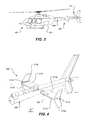
- a rotorcraft 201 is depicted having a tailboom 209 connected to a fuselage 231.
- a tail rotor 233 is operably associated with tailboom 209 for providing a means for torque control.
- a horizontal stabilizer 203 is attached to tailboom 209 in order to provide aerodynamic stability to rotorcraft 201 during flight.
- Horizontal stabilizer 203 comprises a left horizontal airfoil 213a, a right horizontal airfoil 213b, and a spar 205.
- horizontal stabilizer 203 further comprises a left endplate 215a and a right endplate 215b.
- Endplates 215a and 215b are coupled to airfoils 213a and 213b with endplate fasteners 211a and 211b, respectively.
- Left and right endplates 215a and 215b provide aerodynamic yaw stability; however, it should be appreciated that the system of the present application fully contemplates horizontal stabilizer 203 without endplates 215a and 215b.
- horizontal stabilizer 203 also comprises leading edge slats 217a and 217b attached to the forward portions of left horizontal airfoil 213a and right horizontal airfoil 213b, respectively.
- Slats 217a and 217b are meant to optimize desired airflow characteristics of stabilizer 203 at different angle of attacks; however, it should be appreciated that the system of the present application fully contemplates horizontal stabilizer 203 without slats 217a and 217b.
- FIG. 5 is a plan view of horizontal airfoils 213a and 213b coupled to spar 205, and spar 205 coupled to tailboom 209.
- Left horizontal airfoil 213a is coupled to spar 205 with at least one removable airfoil attachment fastener 219a.
- right horizontal airfoil 213b is attached to spar 205 with at least one removable airfoil attachment fastener 219b.
- Fasteners 219a and 219b may be a wide variety of removable fasteners; such as, bolts, screws, and other hardware. It should be appreciated that permanent fasteners, such as rivets, are not preferred.
- the preferred embodiment utilizes two removable airfoil attachment fasteners 219a on the left side, and two removable airfoil attachment fasteners 219b on the right side; however, it is contemplated that other rotorcraft applications may require fewer or greater number of removable fasteners to attach left and right airfoils 213a and 213b to spar 205.
- Spar 205 is coupled to tailboom 209 with spar lug pins 207a and 207b.
- Spar 205 is located-transverse and through tailboom 209.
- the inboard edges of horizontal airfoils 213a and 213b are located adjacent to an outer skin of tailboom 209.
- Spar 205 and horizontal airfoils 213a and 213b are preferably made of carbon fiber and bismaleimide (BMI) resin, and formed in a resin transfer molding (RTM) process.
- BMI bismaleimide
- the RTM process allows the inner and outer surfaces of spar 205 and horizontal airfoils 213a and 213b to be tooled, thereby providing closely controlled tolerances between spar 205 and horizontal airfoils 213a and 213b.
- the closely controlled tolerances between spar 205 and horizontal airfoils 213a and 213b provide an efficient structural load path between airfoils 213a and 213b, and tailboom 209. Load (or forces) acting upon airfoils 213a and 213b translate into spar 205 through structural contact between spar 205 and airfoils 213a and 213b; and further through airfoil attachment fasteners 219a and 219b.
- tailboom 209 load (or forces) acting upon spar 205 translate into an attachment structure 235 of tailboom 209 (as best shown in Figures 7 and 9 ), via spar lug pin 207a and 207b. It is important to note that the primary structural load path does not go through a skin of tailboom 209, rather directly into the internal structure of tailboom 209. The fatigue life and corrosion life of tailboom 209 and horizontal stabilizer 203 are increased by utilizing a minimum number of fasteners and by providing the efficient structural load path as described herein.
- spar 205 and horizontal airfoils 213a and 213b may be manufactured of carbon fiber and bismaleimide (BMI) resin through a resin transfer molding (RTM) process; spar 205 and horizontal airfoils 213a and 213b may also be manufactured out of a metal, such as aluminum, through a machining process. In addition, spar 205 and horizontal airfoils 213a and 213b may also be manufactured from other composite materials and processes.
- BMI carbon fiber and bismaleimide
- RTM resin transfer molding
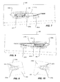
- FIGs 7 and 9 are cross-sectional views looking inboard, taken along section lines VII-VII and IX-IX in Figure 6 , respectively.
- spar 205 is shown having generally rectangular cross section, rounded corners, and a hollow interior, spar 205 may also be of other cross section shapes such as oval, circular, square, or that of an I-beam.
- Spar lug pins 207a and 207b allow for rapid removal and installation of spar 205 to and from tailboom 209.
- Figures 7 and 9 also depict weatherproof seals 229a and 229b between inboard edges of horizontal airfoils 213a and 213b and outer skin of tailboom 209, respectively.
- lug pins 207a and 207b each extend generally in a forward and aft direction, and engage spar 205 with attachment structure 235 of tailboom 209.
- Attachment structure 235 is configured to provide a primary structural path between spar 205 and tailboom 209.
- bushings, washers, cotter pins, safety wire, nuts and other associated hardware may be used with lug pins 207a and 207b in order to provide an appropriate structural connection between spar 205 and attachment structure 235 of tailboom 209.
- Left bonding strap 225a and right bonding strap 225b are connected between tailboom 209 and horizontal airfoils 213a and 213b, respectively.
- Bonding strap 225a is coupled to tailboom 209 and horizontal airfoil 213a.
- Bonding strap fasteners 227a removably attach bonding strap 225a to airfoil 213a.
- bonding strap 225b is coupled to tailboom 209 and horizontal airfoil 213b.
- bonding strap fasteners 227b removably attach bonding strap 225b to airfoil 213b.
- bonding strap fasteners 227a and 227b should be unfastened to facilitate removal of horizontal airfoils 213a and 213b from rotorcraft 201.
- Fasteners 227a and 227b may be a wide variety of removable fasteners; such as, bolts, screws, and other hardware.
- FIG. 11 illustrates horizontal stabilizer 203 assembled, but the remainder of rotorcraft 201 is not shown in order to provide for improved clarity.
- horizontal stabilizer is 203 is illustrated in an exploded view for improved clarity of installation and removal of horizontal stabilizer 203 from tailboom 209.
- Horizontal stabilizer 203 is configured for rapid removal and installation, to and from rotorcraft 201.
- removal of horizontal stabilizer 203 occurs during the process of converting rotorcraft 201 into a stowed configuration.
- installation of horizontal stabilizer 203 occurs when converting rotorcraft 201 into an operable configuration.
- left horizontal airfoil 213a as well as endplate 215a, entails removal of removable airfoil attachment fasteners 219a and bonding strap fasteners 227a. After which, stabilizer 213a can then be slid in an outboard direction 223a away from tailboom 209.
- removal of right horizontal airfoil 213b, as well as endplate 215b entails removal of removable airfoil attachment fasteners 219b and bonding strap fasteners 227b. After which, stabilizer 213b can then be slid in an outboard direction 223b away from tailboom 209.
- tailboom opening 221 can be only large enough for spar 205 to enter tailboom 209. Opening 221 should be too small for horizontal airfoils 213a and 213b to enter tailboom 209; as such, this improved structural efficiency allows for enhanced performance of rotorcraft 201.
- the system of the present application provides significant advantages, including: (1) providing a easily stowable horizontal stabilizer without a heavy folding mechanism; (2) reducing horizontal stabilizer fastener part count so as to decrease labor and maintenance costs, increasing fatigue life, decreasing weight, and reducing likelihood of corrosion; (3) decreasing the amount of time and labor required between horizontal stabilizer stowage and deployment; (4) reducing the size of the opening required within the tailboom so as to improve structural characteristics; and (5) improving rotorcraft performance.
Landscapes
- Engineering & Computer Science (AREA)
- Aviation & Aerospace Engineering (AREA)
- Mechanical Engineering (AREA)
- Laminated Bodies (AREA)
- General Details Of Gearings (AREA)
- Aiming, Guidance, Guns With A Light Source, Armor, Camouflage, And Targets (AREA)
- Toys (AREA)
Description
- The present application relates in general to the field of aerodynamic structures for rotorcraft; but more particularly, horizontal stabilizers for rotorcraft, such as disclosed in document
US 2009/0008498 , which is considered the closest prior art showing the features of the preamble ofindependent claim 1. - There are many different types of rotorcraft, including helicopters, tandem rotor helicopters, tiltrotor aircraft, four-rotor tiltrotor aircraft, tilt wing aircraft, and tail sitter aircraft. At least some of these aforementioned rotorcraft utilize horizontal stabilizers attached to a tailboom in order to provide aerodynamic stability during flight. Typically, a horizontal stabilizer will have one or more horizontal surfaces to aid in aerodynamic pitch stability. Additionally, a horizontal stabilizer may have one or more vertical surfaces to aid in aerodynamic yaw stability. It is often important for a rotorcraft to have the capability of reducing its overall volume for stowage reasons. For example, when transporting multiple rotorcraft in a cargo portion of a cargo plane, it is advantageous to convert the rotorcraft into a stowage configuration. In addition, it is also advantageous to be able to rapidly convert rotorcraft from a stowed configuration to an operable configuration, i.e. rapid deployment.
- Referring to
Figure 1 , arotorcraft 101 is depicted with a conventionalhorizontal stabilizer 103 attached to atailboom 109. A forward end oftailboom 109 is attached tofuselage 119. Atail rotor 121 is carried by an aft end oftailboom 109. - Referring now to
Figure 2 , conventionalhorizontal stabilizer 103 ofrotorcraft 101 is shown in further detail.Horizontal structure 113 extends through an opening intailboom 109 and is permanently attached toskin 111 oftailboom 109 withfasteners 107.Endplates horizontal structure 113 with a plurality ofendplate fasteners Folding mechanisms horizontal structure 113. Forhorizontal stabilizer 103 to be in a stowable configuration,endplates fasteners horizontal structure 113 is permanently attached totailboom 109,folding mechanism structure 113 to fold upward to a stowed position. - It is often desirable to create more efficient rotorcraft structure, thereby reducing the number of fasteners, reducing weight, and decreasing the amount of time it takes to stow and deploy an aircraft. There are many rotorcraft horizontal stabilizers known in the art; however, considerable room for improvement remains.
- The novel features believed characteristic of the system of the present application are set forth in the appended claims. However, the system itself, as well as, a preferred mode of use, and further objectives and advantages thereof, will best be understood by reference to the following detailed description when read in conjunction with the accompanying drawings, wherein:
-
Figure 1 is a side view of a rotorcraft with a prior art horizontal stabilizer; -
Figure 2 is a perspective view of the prior art horizontal stabilizer from the rotorcraft ofFigure 1 ; -
Figure 3 is a side view of a rotorcraft having a horizontal stabilizer according the preferred embodiment of the present application; -
Figure 4 is a perspective view of the horizontal stabilizer from the aircraft inFigure 3 , according to the preferred embodiment of the present application; -
Figure 5 is a plan view of the horizontal stabilizer ofFigure 4 , according to the preferred embodiment of the present application; -
Figure 6 is a partial cross-sectional view of the horizontal stabilizer, taken along the section lines VI-VI shown inFigure 5 , according to the preferred embodiment of the present application; -
Figure 7 is a partial cross-sectional view of the horizontal stabilizer, taken along the section lines VII-VII shown inFigure 6 , according to the preferred embodiment of the present application; -
Figure 8 is a bottom view of the horizontal stabilizer bonding strap shown inFigure 7 , according to the preferred embodiment of the present application; -
Figure 9 is a partial cross-sectional view of the horizontal stabilizer, taken along the lines IX-IX shown inFigure 6 , according to the preferred embodiment of the present application; -
Figure 10 is a bottom view of the horizontal stabilizer bonding strap shown inFigure 9 , according to the preferred embodiment of the present application; -
Figure 11 is a perspective view of the horizontal stabilizer ofFigure 4 , according to the preferred embodiment of the present application; and -
Figure 12 is an exploded perspective view of the horizontal stabilizer ofFigure 4 , removed from the rotorcraft, according to the preferred embodiment of the present application. - While the system of the present application is susceptible to various modifications and alternative forms, specific embodiments thereof have been shown by way of example in the drawings and are herein described in detail. It should be understood, however, that the description herein of specific embodiments is not intended to limit the system to the particular forms disclosed, but on the contrary, the intention is to cover all modifications, equivalents, and alternatives falling within the scope of the present application as defined by the appended claims.
- Illustrative embodiments of the system of the present application are described below. In the interest of clarity, not all features of an actual implementation are described in this specification. It will of course be appreciated that in the development of any such actual embodiment, numerous implementation-specific decisions must be made to achieve the developer's specific goals, such as compliance with system-related and business-related constraints, which will vary from one implementation to another. Moreover, it will be appreciated that such a development effort might be complex and time-consuming but would nevertheless be a routine undertaking for those of ordinary skill in the art having the benefit of this disclosure.
- In the specification, reference may be made to the spatial relationships between various components and to the spatial orientation of various aspects of components as the devices are depicted in the attached drawings. However, as will be recognized by those skilled in the art after a complete reading of the present application, the devices, members, apparatuses, etc. described herein may be positioned in any desired orientation. Thus, the use of terms such as "above," "below," "upper," "lower," or other like terms to describe a spatial relationship between various components or to describe the spatial orientation of aspects of such components should be understood to describe a relative relationship between the components or a spatial orientation of aspects of such components, respectively, as the device described herein may be oriented in any desired direction.
- The system of the present application represents a horizontal stabilizer for a rotorcraft and a rotorcraft incorporating the horizontal stabilizer. The horizontal stabilizer of the present application allows for improved rotorcraft functionality. It should also be appreciated that for this application, the term "left" is synonymous with the term "first" and the term "right" is synonymous with the term "second."
- Referring to
Figure 3 , arotorcraft 201 is depicted having atailboom 209 connected to a fuselage 231. Atail rotor 233 is operably associated withtailboom 209 for providing a means for torque control. Ahorizontal stabilizer 203 is attached totailboom 209 in order to provide aerodynamic stability torotorcraft 201 during flight. - Referring now to
Figure 4 ,horizontal stabilizer 203 is shown in greater detail.Horizontal stabilizer 203 comprises a lefthorizontal airfoil 213a, a righthorizontal airfoil 213b, and aspar 205. In the preferred embodiment,horizontal stabilizer 203 further comprises aleft endplate 215a and aright endplate 215b.Endplates airfoils endplate fasteners right endplates horizontal stabilizer 203 withoutendplates horizontal stabilizer 203 also comprises leadingedge slats horizontal airfoil 213a and righthorizontal airfoil 213b, respectively.Slats stabilizer 203 at different angle of attacks; however, it should be appreciated that the system of the present application fully contemplateshorizontal stabilizer 203 withoutslats - Referring now to
Figure 5 , which is a plan view ofhorizontal airfoils spar 205 coupled totailboom 209. Lefthorizontal airfoil 213a is coupled to spar 205 with at least one removableairfoil attachment fastener 219a. Similarly, righthorizontal airfoil 213b is attached to spar 205 with at least one removableairfoil attachment fastener 219b. Fasteners 219a and 219b may be a wide variety of removable fasteners; such as, bolts, screws, and other hardware. It should be appreciated that permanent fasteners, such as rivets, are not preferred. Removal of permanent fasteners typically requires destruction of the permanent fastener, requires a time consuming process, and poses a risk of harmful effects upon surrounding structure. As shown inFigure 5 , the preferred embodiment utilizes two removableairfoil attachment fasteners 219a on the left side, and two removableairfoil attachment fasteners 219b on the right side; however, it is contemplated that other rotorcraft applications may require fewer or greater number of removable fasteners to attach left andright airfoils - Referring now to
Figure 6 , which is a cross-sectional view, taken along section lines VI-VI inFigure 5 .Spar 205 is coupled to tailboom 209 withspar lug pins Spar 205 is located-transverse and throughtailboom 209. The inboard edges ofhorizontal airfoils tailboom 209.Spar 205 andhorizontal airfoils spar 205 andhorizontal airfoils spar 205 andhorizontal airfoils spar 205 andhorizontal airfoils airfoils tailboom 209. Load (or forces) acting uponairfoils spar 205 through structural contact betweenspar 205 andairfoils airfoil attachment fasteners spar 205 translate into anattachment structure 235 of tailboom 209 (as best shown inFigures 7 and 9 ), viaspar lug pin tailboom 209, rather directly into the internal structure oftailboom 209. The fatigue life and corrosion life oftailboom 209 andhorizontal stabilizer 203 are increased by utilizing a minimum number of fasteners and by providing the efficient structural load path as described herein. It should be noted that even though it is preferable forspar 205 andhorizontal airfoils horizontal airfoils spar 205 andhorizontal airfoils - Referring now to
Figures 7 and 9 , which are cross-sectional views looking inboard, taken along section lines VII-VII and IX-IX inFigure 6 , respectively. Thoughspar 205 is shown having generally rectangular cross section, rounded corners, and a hollow interior, spar 205 may also be of other cross section shapes such as oval, circular, square, or that of an I-beam.Spar lug pins spar 205 to and fromtailboom 209.Figures 7 and 9 also depictweatherproof seals horizontal airfoils tailboom 209, respectively. As shown inFigures 7 and 9 ,lug pins spar 205 withattachment structure 235 oftailboom 209.Attachment structure 235 is configured to provide a primary structural path betweenspar 205 andtailboom 209. It should be appreciated that bushings, washers, cotter pins, safety wire, nuts and other associated hardware may be used withlug pins spar 205 andattachment structure 235 oftailboom 209.Left bonding strap 225a andright bonding strap 225b are connected betweentailboom 209 andhorizontal airfoils - Referring now to
Figures 8 and 10 , which are bottom views ofbonding straps Left bonding strap 225a andright bonding strap 225b provide lightning strike bonding paths betweentailboom 209 andhorizontal airfoils bonding straps horizontal stabilizer 203 onrotorcraft 201; in addition, other forms of lightning strike protection may be used to replace or supplementbonding straps Bonding strap 225a is coupled totailboom 209 andhorizontal airfoil 213a.Bonding strap fasteners 227a removably attachbonding strap 225a toairfoil 213a. Similarly,bonding strap 225b is coupled totailboom 209 andhorizontal airfoil 213b. Similarly,bonding strap fasteners 227b removably attachbonding strap 225b toairfoil 213b. As such,bonding strap fasteners horizontal airfoils rotorcraft 201.Fasteners - Referring now to
Figures 11 and12 , in whichFigure 11 illustrateshorizontal stabilizer 203 assembled, but the remainder ofrotorcraft 201 is not shown in order to provide for improved clarity. InFigure 12 , horizontal stabilizer is 203 is illustrated in an exploded view for improved clarity of installation and removal ofhorizontal stabilizer 203 fromtailboom 209.Horizontal stabilizer 203 is configured for rapid removal and installation, to and fromrotorcraft 201. In the preferred embodiment, removal ofhorizontal stabilizer 203 occurs during the process of convertingrotorcraft 201 into a stowed configuration. Similarly, installation ofhorizontal stabilizer 203 occurs when convertingrotorcraft 201 into an operable configuration. Removal of lefthorizontal airfoil 213a, as well asendplate 215a, entails removal of removableairfoil attachment fasteners 219a andbonding strap fasteners 227a. After which,stabilizer 213a can then be slid in anoutboard direction 223a away fromtailboom 209. Similarly, removal of righthorizontal airfoil 213b, as well asendplate 215b, entails removal of removableairfoil attachment fasteners 219b andbonding strap fasteners 227b. After which,stabilizer 213b can then be slid in anoutboard direction 223b away fromtailboom 209. During this process, it may be necessary to disconnect any electrical harnesses, or other systems related hardware, that may be routed throughtailboom 209 and intohorizontal stabilizer 203. Removal ofspar 205 entails removal ofspar lug pins Figures 7 and 9 ), and then slidingspar 205 out of atailboom opening 221 in eitheroutboard direction 223a oroutboard direction 223b. It should be noted that it is not required to removeendplates horizontal airfoils horizontal stabilizer 203 fromrotorcraft 201. Installation ofhorizontal stabilizer 203 is the reverse process of removal ofhorizontal stabilizer 203, as previously described. For purposes of this application, removal ofhorizontal stabilizer 203 is equivalent to stowing ofhorizontal stabilizer 203, and installation ofhorizontal stabilizer 203 is equivalent to deployment ofhorizontal stabilizer 203. It should also be noted that tailboom opening 221 can be only large enough forspar 205 to entertailboom 209. Opening 221 should be too small forhorizontal airfoils tailboom 209; as such, this improved structural efficiency allows for enhanced performance ofrotorcraft 201. - The system of the present application provides significant advantages, including: (1) providing a easily stowable horizontal stabilizer without a heavy folding mechanism; (2) reducing horizontal stabilizer fastener part count so as to decrease labor and maintenance costs, increasing fatigue life, decreasing weight, and reducing likelihood of corrosion; (3) decreasing the amount of time and labor required between horizontal stabilizer stowage and deployment; (4) reducing the size of the opening required within the tailboom so as to improve structural characteristics; and (5) improving rotorcraft performance.
- It is apparent that a system with significant advantages has been described and illustrated. Although the system of the present application is shown in a limited number of forms, it is not limited to just these forms, but is amenable to various changes and modifications without departing from the scope of the claims.
Claims (14)
- A removable horizontal stabilizer (203) configured to provide aerodynamic stability for a rotorcraft (201) having a tailboom (209), the horizontal stabilizer comprising:a first horizontal airfoil; a second horizontal airfoil; characterised in that it further comprises:a spar (205) configured to be transversely located at least partially inside an opening in the tailboom;a removable spar attachment member for structural attaching the spar to the tailboom;a first removable airfoil attachment member (219a) for structurally attaching the first horizontal airfoil to the spar; anda second removable airfoil attachment member (219b) for structurally attaching the second horizontal airfoil to the spar;wherein the first horizontal airfoil (113a) is adapted to fittingly receive the spar;wherein the second horizontal airfoil (113b) is adapted to fittingly receive the spar;wherein the first and second horizontal airfoils extend in opposite outboard directions from the tailboom so as to provide aerodynamic pitch stability;wherein the spar is configured to provide structural support for the first and second horizontal airfoils.
- The horizontal stabilizer according to claim 1, wherein the spar (205) has generally a rectangular cross sectional shape.
- The horizontal stabilizer according to claim 1, further comprising:a first vertical endplate (215a) coupled to the first horizontal airfoil; anda second vertical endplate (215b) coupled to the second horizontal airfoil;wherein the first and second vertical endplates provide aerodynamic yaw stability for the rotorcraft.
- The horizontal stabilizer according to claim 1, further comprising:a first bonding strap (225a) removably fastened to the first horizontal airfoil for providing a ground path between the first horizontal airfoil and the tailboom; anda second bonding strap (225b) removably fastened to the second horizontal airfoil for providing a ground path between the second horizontal airfoil and the tailboom.
- The horizontal stabilizer according to claim 1, wherein the removable spar attachment member comprises a lug pin (207a, 207b).
- The horizontal stabilizer according to claim 1, further comprising:a first seal (229a) positioned between an inboard edge of the first horizontal airfoil and the tailboom; anda second seal (229b) positioned between an inboard edge of the second horizontal airfoil and the tailboom.
- The horizontal stabilizer according to claim 1, wherein the first horizontal airfoil (213a) is configured for removal from the rotorcraft by removing the first removable airfoil attachment member and sliding the first horizontal airfoil outboard; and wherein the second horizontal airfoil (213b) is configured for removal from the rotorcraft by removing the second removable airfoil attachment member and sliding the second horizontal airfoil outboard.
- The horizontal stabilizer according to claim 1, wherein the spar (205) is configured for removal from the rotorcraft by removing the removable first and second spar attachment members, and sliding the spar laterally away from the tailboom.
- The horizontal stabilizer according to claim 1, further comprising:a stationary leading edge slat (217a, 217b) attached to the left and right horizontal airfoils so as to optimize airflow characteristics of the left and right horizontal airfoils at different angle of attacks.
- The horizontal stabilizer according to claim 1, wherein at least one of the spar (205), the first horizontal airfoil (213a), and the second horizontal airfoil (213b), is formed from a resin transfer molding process.
- The horizontal stabilizer according to claim 1, further comprising a stationary leading edge slat (217a, 217b) for tailoring airflow across the first and second horizontal airfoils.
- The horizontal stabilizer according to claim 1, wherein at least one of the spar (205), the first horizontal airfoil (213a), and the second horizontal airfoil (213b) comprises carbon fiber and bismaleimide (BMI) resin.
- A method of converting a helicopter into a stowed configuration by removing a horizontal stabilizer (203), comprising:removing a first and a second removable airfoil attachment member (219a, 219b),removing a first and a second horizontal airfoil (213a, 213b) by sliding each airfoil from a tailboom portion in an outboard direction;removing at least one removable spar attachment member; andremoving a spar (205) by sliding the spar away from the tailboom portion of the helicopter;wherein removal of the spar and the first and second horizontal airfoil from the tailboom portion reduces a volume of the helicopter so as to facilitate stowage of the helicopter.
- A method of converting a helicopter from a stowed configuration to an operable configuration by instating a horizontal stabilizer (203), comprising:attaching a spar (205) by sliding the spar into a tailboom portion of the helicopter;coupling the spar to the tailboom with at least one removable spar attachment member;sliding a first and a second horizontal airfoil (213a, 213b) upon the spar from opposite outboard directions;attaching the first and second horizontal airfoil to the spar with at least one removable airfoil attachment member (219a, 219b);wherein installation of the spar, and the first and second horizontal airfoil facilitates operation of the helicopter.
Applications Claiming Priority (1)
| Application Number | Priority Date | Filing Date | Title |
|---|---|---|---|
| PCT/US2009/057261 WO2011034531A1 (en) | 2009-09-17 | 2009-09-17 | Removable horizontal stabilizer for helicopter |
Publications (3)
| Publication Number | Publication Date |
|---|---|
| EP2477890A1 EP2477890A1 (en) | 2012-07-25 |
| EP2477890A4 EP2477890A4 (en) | 2013-02-27 |
| EP2477890B1 true EP2477890B1 (en) | 2013-11-06 |
Family
ID=43758919
Family Applications (1)
| Application Number | Title | Priority Date | Filing Date |
|---|---|---|---|
| EP09849618.5A Active EP2477890B1 (en) | 2009-09-17 | 2009-09-17 | Removable horizontal stabilizer for helicopter |
Country Status (6)
| Country | Link |
|---|---|
| US (2) | US8602351B2 (en) |
| EP (1) | EP2477890B1 (en) |
| CN (1) | CN102574570B (en) |
| CA (1) | CA2771482C (en) |
| IN (1) | IN2012DN02173A (en) |
| WO (1) | WO2011034531A1 (en) |
Families Citing this family (9)
| Publication number | Priority date | Publication date | Assignee | Title |
|---|---|---|---|---|
| FR2990926B1 (en) * | 2012-05-22 | 2014-11-28 | Eurocopter France | TANGING STABILIZATION MEANS AND ROTARY SAILING AIRCRAFT PROVIDED WITH SUCH MEANS |
| US9884674B2 (en) * | 2012-11-15 | 2018-02-06 | United Technologies Corporation | Stabilizer with structural box and sacrificial surfaces |
| CN105620789A (en) * | 2016-02-23 | 2016-06-01 | 哈尔滨飞机工业集团有限责任公司 | Horizontal tail lengthening box section |
| GB2547957A (en) | 2016-05-24 | 2017-09-06 | Airbus Operations Ltd | Winglet |
| US10696374B2 (en) * | 2016-11-21 | 2020-06-30 | Yevgeniy Il'ich Sher | Composite material and aircraft improvements |
| CN108082530B (en) * | 2017-12-03 | 2021-02-26 | 中国直升机设计研究所 | Helicopter full-motion horizontal tail steering engine installation calculation method |
| US10618627B2 (en) * | 2018-02-13 | 2020-04-14 | Bell Helicopter Textron Inc. | Rudder twist lock method and apparatus |
| RU2715249C1 (en) * | 2019-07-30 | 2020-02-26 | Акционерное общество "Национальный центр вертолетостроения им. М.Л. Миля и Н.И. Камова" (АО "НЦВ Миль и Камов") | Helicopter stabilizer |
| CN110789709B (en) * | 2019-10-12 | 2022-10-11 | 哈尔滨飞机工业集团有限责任公司 | Composite horizontal tail with leading edge slat |
Family Cites Families (31)
| Publication number | Priority date | Publication date | Assignee | Title |
|---|---|---|---|---|
| US2959373A (en) * | 1954-12-10 | 1960-11-08 | Daniel R Zuck | Convertiplane |
| US3081052A (en) * | 1957-06-03 | 1963-03-12 | United Aircraft Corp | Variable stabilizing means |
| US3260482A (en) | 1964-12-03 | 1966-07-12 | Piasecki Aircraft Corp | Directional control assembly |
| GB1084537A (en) | 1965-07-31 | 1967-09-27 | Rolls Royce | A compressor or turbine rotor for a gas turbine engine |
| US3409248A (en) | 1965-10-22 | 1968-11-05 | Harvard J. Bryan | Rotary winged aircraft with drag propelling rotors and controls |
| FR2067224B1 (en) | 1969-11-27 | 1974-05-24 | Aerospatiale | |
| US4034939A (en) * | 1975-11-05 | 1977-07-12 | The Boeing Company | Assembly for sealing the mounting opening for a flying horizontal stabilizer on a vertical stabilizer |
| US4227665A (en) * | 1978-05-11 | 1980-10-14 | Textron, Inc. | Fixed leading edge slat spoiler for a horizontal stabilizer |
| US4247061A (en) * | 1978-07-12 | 1981-01-27 | United Technologies Corporation | Helicopter with stabilator detuned in antisymmetric vibration modes from main rotor wake excitation frequency |
| US5056741A (en) * | 1989-09-29 | 1991-10-15 | The Boeing Company | Apparatus and method for aircraft wing stall control |
| US5094412A (en) * | 1989-10-13 | 1992-03-10 | Bell Helicopter Textron Inc. | Flaperon system for tilt rotor wings |
| US5205714A (en) | 1990-07-30 | 1993-04-27 | General Electric Company | Aircraft fan blade damping apparatus |
| US5209430A (en) * | 1991-11-07 | 1993-05-11 | The United States Of America As Represented By The Administrator Of The National Aeronautics And Space Administration | Helicopter low-speed yaw control |
| JP2533041B2 (en) | 1992-08-07 | 1996-09-11 | 大平洋特殊鋳造株式会社 | Suspension preheater cyclone inner cylinder |
| JPH06101997A (en) * | 1992-09-17 | 1994-04-12 | Nissan Motor Co Ltd | Stable wing fixing structure for flying objects |
| US5377934A (en) * | 1993-01-25 | 1995-01-03 | Hill; Jamie R. | Helicopter conversion |
| US5641133A (en) * | 1994-05-11 | 1997-06-24 | Mcdonnell Douglas Helicopter Co. | Rotorcraft fuselage modal frequency placement using resilient mounting connections |
| US5645249A (en) * | 1994-08-29 | 1997-07-08 | Mcdonnell Douglas Corporation | Helicopter stowable horizontal stabilizer |
| US5547629A (en) * | 1994-09-27 | 1996-08-20 | Competition Composites, Inc. | Method for manufacturing a one-piece molded composite airfoil |
| US5727754A (en) * | 1995-08-31 | 1998-03-17 | Cartercopters, L.L.C. | Gyroplane |
| US5807454A (en) * | 1995-09-05 | 1998-09-15 | Honda Giken Kogyo Kabushiki Kaisha | Method of maufacturing a leading edge structure for aircraft |
| US6024325A (en) * | 1997-01-09 | 2000-02-15 | Cartercopters, Llc | Rotor for rotary wing aircraft |
| EP1286873B1 (en) | 2000-05-18 | 2004-11-17 | Wingship Limited | Wing in ground effect vehicle with endplates |
| US6830214B2 (en) * | 2002-07-12 | 2004-12-14 | Franklin D. Carson | Rotary-wing aircraft |
| FR2864026B1 (en) * | 2003-12-23 | 2007-01-19 | Eurocopter France | METHOD AND DEVICE FOR REDUCING WITH AN ORIENTABLE DRIVE THE VIBRATIONS GENERATED ON THE FUSELAGE OF A HELICOPTER |
| US7275711B1 (en) * | 2004-02-23 | 2007-10-02 | Kenneth Warren Flanigan | Gas-powered tip-jet-driven compound VTOL aircraft |
| US7182293B2 (en) * | 2004-04-27 | 2007-02-27 | The Boeing Company | Airfoil box and associated method |
| US7246998B2 (en) * | 2004-11-18 | 2007-07-24 | Sikorsky Aircraft Corporation | Mission replaceable rotor blade tip section |
| US8210468B2 (en) * | 2007-05-14 | 2012-07-03 | Blr Aerospace, L.L.C. | Aircraft stabilizer system and methods of using the same |
| US7975965B2 (en) * | 2008-05-13 | 2011-07-12 | The Boeing Company | Wing tip joint in airfoils |
| ITTO20080445A1 (en) * | 2008-06-09 | 2009-12-10 | Agusta Spa | SEMIALA FOR AN AIRCRAFT |
-
2009
- 2009-09-17 US US13/496,241 patent/US8602351B2/en active Active
- 2009-09-17 EP EP09849618.5A patent/EP2477890B1/en active Active
- 2009-09-17 CN CN200980161273.1A patent/CN102574570B/en not_active Expired - Fee Related
- 2009-09-17 WO PCT/US2009/057261 patent/WO2011034531A1/en not_active Ceased
- 2009-09-17 IN IN2173DEN2012 patent/IN2012DN02173A/en unknown
- 2009-09-17 CA CA2771482A patent/CA2771482C/en active Active
-
2013
- 2013-11-25 US US14/088,506 patent/US8882031B2/en active Active
Also Published As
| Publication number | Publication date |
|---|---|
| EP2477890A1 (en) | 2012-07-25 |
| WO2011034531A1 (en) | 2011-03-24 |
| EP2477890A4 (en) | 2013-02-27 |
| CA2771482C (en) | 2015-03-17 |
| CA2771482A1 (en) | 2011-03-24 |
| US20120168559A1 (en) | 2012-07-05 |
| US20140077029A1 (en) | 2014-03-20 |
| US8602351B2 (en) | 2013-12-10 |
| CN102574570B (en) | 2014-11-12 |
| IN2012DN02173A (en) | 2015-08-21 |
| US8882031B2 (en) | 2014-11-11 |
| CN102574570A (en) | 2012-07-11 |
Similar Documents
| Publication | Publication Date | Title |
|---|---|---|
| CA2771482C (en) | Removable horizontal stabilizer for helicopter | |
| EP1934090B1 (en) | Integrated wingtip extension and method of increasing the wing area of a baseline aircraft | |
| EP3114030B1 (en) | Engine pylon structure | |
| US10246181B2 (en) | Method for attaching a split winglet to a wing | |
| US7887009B2 (en) | Methods and systems for attaching aircraft wings to fuselages | |
| US9533768B2 (en) | Aircraft engine mounting system | |
| US6929219B2 (en) | Derivative aircraft and methods for their manufacture | |
| US11148792B2 (en) | Compound helicopter with a fixed wing arrangement | |
| EP0532016B1 (en) | Composite focused load control surface | |
| CA2898470A1 (en) | Aircraft landing gear and method of operating the same | |
| WO2010032241A1 (en) | Aerofoil accessories and method for modyfying the geometry of a wing element | |
| EP4116188B1 (en) | Aerofoil of an aerodynamic surface | |
| US12503217B2 (en) | Moveable wing tip arrangements | |
| EP3486171B1 (en) | Braced wing aircraft | |
| WO2008103735A2 (en) | Aircraft, and retrofit components therefor | |
| EP3321185B1 (en) | Integrated strut support fittings with underwing longerons | |
| EP4365083B1 (en) | SYSTEMS AND METHOD FOR COUPLING A STRUT TO A WING OF AN AIRCRAFT | |
| CA3027273C (en) | Braced wing aircraft |
Legal Events
| Date | Code | Title | Description |
|---|---|---|---|
| PUAI | Public reference made under article 153(3) epc to a published international application that has entered the european phase |
Free format text: ORIGINAL CODE: 0009012 |
|
| 17P | Request for examination filed |
Effective date: 20120217 |
|
| AK | Designated contracting states |
Kind code of ref document: A1 Designated state(s): AT BE BG CH CY CZ DE DK EE ES FI FR GB GR HR HU IE IS IT LI LT LU LV MC MK MT NL NO PL PT RO SE SI SK SM TR |
|
| DAX | Request for extension of the european patent (deleted) | ||
| A4 | Supplementary search report drawn up and despatched |
Effective date: 20130124 |
|
| RIC1 | Information provided on ipc code assigned before grant |
Ipc: B64C 1/26 20060101ALI20130118BHEP Ipc: B64C 5/02 20060101ALI20130118BHEP Ipc: B64C 3/00 20060101ALI20130118BHEP Ipc: B64C 1/00 20060101AFI20130118BHEP Ipc: B64C 5/00 20060101ALI20130118BHEP |
|
| RIC1 | Information provided on ipc code assigned before grant |
Ipc: B64C 1/00 20060101AFI20130610BHEP Ipc: B64C 5/00 20060101ALI20130610BHEP Ipc: B64C 27/04 20060101ALI20130610BHEP Ipc: B64C 5/02 20060101ALI20130610BHEP Ipc: B64C 1/26 20060101ALI20130610BHEP Ipc: B64C 3/00 20060101ALI20130610BHEP |
|
| GRAP | Despatch of communication of intention to grant a patent |
Free format text: ORIGINAL CODE: EPIDOSNIGR1 |
|
| INTG | Intention to grant announced |
Effective date: 20130813 |
|
| GRAS | Grant fee paid |
Free format text: ORIGINAL CODE: EPIDOSNIGR3 |
|
| GRAA | (expected) grant |
Free format text: ORIGINAL CODE: 0009210 |
|
| AK | Designated contracting states |
Kind code of ref document: B1 Designated state(s): AT BE BG CH CY CZ DE DK EE ES FI FR GB GR HR HU IE IS IT LI LT LU LV MC MK MT NL NO PL PT RO SE SI SK SM TR |
|
| REG | Reference to a national code |
Ref country code: GB Ref legal event code: FG4D |
|
| REG | Reference to a national code |
Ref country code: CH Ref legal event code: EP |
|
| REG | Reference to a national code |
Ref country code: AT Ref legal event code: REF Ref document number: 639269 Country of ref document: AT Kind code of ref document: T Effective date: 20131215 |
|
| REG | Reference to a national code |
Ref country code: IE Ref legal event code: FG4D |
|
| REG | Reference to a national code |
Ref country code: DE Ref legal event code: R096 Ref document number: 602009020027 Country of ref document: DE Effective date: 20140102 |
|
| REG | Reference to a national code |
Ref country code: NL Ref legal event code: VDEP Effective date: 20131106 |
|
| REG | Reference to a national code |
Ref country code: AT Ref legal event code: MK05 Ref document number: 639269 Country of ref document: AT Kind code of ref document: T Effective date: 20131106 |
|
| REG | Reference to a national code |
Ref country code: LT Ref legal event code: MG4D |
|
| PG25 | Lapsed in a contracting state [announced via postgrant information from national office to epo] |
Ref country code: NO Free format text: LAPSE BECAUSE OF FAILURE TO SUBMIT A TRANSLATION OF THE DESCRIPTION OR TO PAY THE FEE WITHIN THE PRESCRIBED TIME-LIMIT Effective date: 20140206 Ref country code: LT Free format text: LAPSE BECAUSE OF FAILURE TO SUBMIT A TRANSLATION OF THE DESCRIPTION OR TO PAY THE FEE WITHIN THE PRESCRIBED TIME-LIMIT Effective date: 20131106 Ref country code: SE Free format text: LAPSE BECAUSE OF FAILURE TO SUBMIT A TRANSLATION OF THE DESCRIPTION OR TO PAY THE FEE WITHIN THE PRESCRIBED TIME-LIMIT Effective date: 20131106 Ref country code: FI Free format text: LAPSE BECAUSE OF FAILURE TO SUBMIT A TRANSLATION OF THE DESCRIPTION OR TO PAY THE FEE WITHIN THE PRESCRIBED TIME-LIMIT Effective date: 20131106 Ref country code: HR Free format text: LAPSE BECAUSE OF FAILURE TO SUBMIT A TRANSLATION OF THE DESCRIPTION OR TO PAY THE FEE WITHIN THE PRESCRIBED TIME-LIMIT Effective date: 20131106 Ref country code: IS Free format text: LAPSE BECAUSE OF FAILURE TO SUBMIT A TRANSLATION OF THE DESCRIPTION OR TO PAY THE FEE WITHIN THE PRESCRIBED TIME-LIMIT Effective date: 20140306 Ref country code: NL Free format text: LAPSE BECAUSE OF FAILURE TO SUBMIT A TRANSLATION OF THE DESCRIPTION OR TO PAY THE FEE WITHIN THE PRESCRIBED TIME-LIMIT Effective date: 20131106 |
|
| PG25 | Lapsed in a contracting state [announced via postgrant information from national office to epo] |
Ref country code: BE Free format text: LAPSE BECAUSE OF FAILURE TO SUBMIT A TRANSLATION OF THE DESCRIPTION OR TO PAY THE FEE WITHIN THE PRESCRIBED TIME-LIMIT Effective date: 20131106 Ref country code: ES Free format text: LAPSE BECAUSE OF FAILURE TO SUBMIT A TRANSLATION OF THE DESCRIPTION OR TO PAY THE FEE WITHIN THE PRESCRIBED TIME-LIMIT Effective date: 20131106 Ref country code: LV Free format text: LAPSE BECAUSE OF FAILURE TO SUBMIT A TRANSLATION OF THE DESCRIPTION OR TO PAY THE FEE WITHIN THE PRESCRIBED TIME-LIMIT Effective date: 20131106 Ref country code: AT Free format text: LAPSE BECAUSE OF FAILURE TO SUBMIT A TRANSLATION OF THE DESCRIPTION OR TO PAY THE FEE WITHIN THE PRESCRIBED TIME-LIMIT Effective date: 20131106 |
|
| PG25 | Lapsed in a contracting state [announced via postgrant information from national office to epo] |
Ref country code: PT Free format text: LAPSE BECAUSE OF FAILURE TO SUBMIT A TRANSLATION OF THE DESCRIPTION OR TO PAY THE FEE WITHIN THE PRESCRIBED TIME-LIMIT Effective date: 20140306 |
|
| PG25 | Lapsed in a contracting state [announced via postgrant information from national office to epo] |
Ref country code: EE Free format text: LAPSE BECAUSE OF FAILURE TO SUBMIT A TRANSLATION OF THE DESCRIPTION OR TO PAY THE FEE WITHIN THE PRESCRIBED TIME-LIMIT Effective date: 20131106 |
|
| REG | Reference to a national code |
Ref country code: DE Ref legal event code: R097 Ref document number: 602009020027 Country of ref document: DE |
|
| PG25 | Lapsed in a contracting state [announced via postgrant information from national office to epo] |
Ref country code: RO Free format text: LAPSE BECAUSE OF FAILURE TO SUBMIT A TRANSLATION OF THE DESCRIPTION OR TO PAY THE FEE WITHIN THE PRESCRIBED TIME-LIMIT Effective date: 20131106 Ref country code: PL Free format text: LAPSE BECAUSE OF FAILURE TO SUBMIT A TRANSLATION OF THE DESCRIPTION OR TO PAY THE FEE WITHIN THE PRESCRIBED TIME-LIMIT Effective date: 20131106 Ref country code: CZ Free format text: LAPSE BECAUSE OF FAILURE TO SUBMIT A TRANSLATION OF THE DESCRIPTION OR TO PAY THE FEE WITHIN THE PRESCRIBED TIME-LIMIT Effective date: 20131106 Ref country code: SK Free format text: LAPSE BECAUSE OF FAILURE TO SUBMIT A TRANSLATION OF THE DESCRIPTION OR TO PAY THE FEE WITHIN THE PRESCRIBED TIME-LIMIT Effective date: 20131106 |
|
| PLBE | No opposition filed within time limit |
Free format text: ORIGINAL CODE: 0009261 |
|
| STAA | Information on the status of an ep patent application or granted ep patent |
Free format text: STATUS: NO OPPOSITION FILED WITHIN TIME LIMIT |
|
| PG25 | Lapsed in a contracting state [announced via postgrant information from national office to epo] |
Ref country code: DK Free format text: LAPSE BECAUSE OF FAILURE TO SUBMIT A TRANSLATION OF THE DESCRIPTION OR TO PAY THE FEE WITHIN THE PRESCRIBED TIME-LIMIT Effective date: 20131106 |
|
| 26N | No opposition filed |
Effective date: 20140807 |
|
| REG | Reference to a national code |
Ref country code: DE Ref legal event code: R097 Ref document number: 602009020027 Country of ref document: DE Effective date: 20140807 |
|
| PG25 | Lapsed in a contracting state [announced via postgrant information from national office to epo] |
Ref country code: SI Free format text: LAPSE BECAUSE OF FAILURE TO SUBMIT A TRANSLATION OF THE DESCRIPTION OR TO PAY THE FEE WITHIN THE PRESCRIBED TIME-LIMIT Effective date: 20131106 |
|
| PG25 | Lapsed in a contracting state [announced via postgrant information from national office to epo] |
Ref country code: LU Free format text: LAPSE BECAUSE OF FAILURE TO SUBMIT A TRANSLATION OF THE DESCRIPTION OR TO PAY THE FEE WITHIN THE PRESCRIBED TIME-LIMIT Effective date: 20140917 Ref country code: MC Free format text: LAPSE BECAUSE OF FAILURE TO SUBMIT A TRANSLATION OF THE DESCRIPTION OR TO PAY THE FEE WITHIN THE PRESCRIBED TIME-LIMIT Effective date: 20131106 |
|
| REG | Reference to a national code |
Ref country code: CH Ref legal event code: PL |
|
| REG | Reference to a national code |
Ref country code: IE Ref legal event code: MM4A |
|
| PG25 | Lapsed in a contracting state [announced via postgrant information from national office to epo] |
Ref country code: CH Free format text: LAPSE BECAUSE OF NON-PAYMENT OF DUE FEES Effective date: 20140930 Ref country code: LI Free format text: LAPSE BECAUSE OF NON-PAYMENT OF DUE FEES Effective date: 20140930 |
|
| PG25 | Lapsed in a contracting state [announced via postgrant information from national office to epo] |
Ref country code: IE Free format text: LAPSE BECAUSE OF NON-PAYMENT OF DUE FEES Effective date: 20140917 |
|
| PG25 | Lapsed in a contracting state [announced via postgrant information from national office to epo] |
Ref country code: SM Free format text: LAPSE BECAUSE OF FAILURE TO SUBMIT A TRANSLATION OF THE DESCRIPTION OR TO PAY THE FEE WITHIN THE PRESCRIBED TIME-LIMIT Effective date: 20131106 |
|
| PG25 | Lapsed in a contracting state [announced via postgrant information from national office to epo] |
Ref country code: BG Free format text: LAPSE BECAUSE OF FAILURE TO SUBMIT A TRANSLATION OF THE DESCRIPTION OR TO PAY THE FEE WITHIN THE PRESCRIBED TIME-LIMIT Effective date: 20131106 Ref country code: CY Free format text: LAPSE BECAUSE OF FAILURE TO SUBMIT A TRANSLATION OF THE DESCRIPTION OR TO PAY THE FEE WITHIN THE PRESCRIBED TIME-LIMIT Effective date: 20131106 Ref country code: GR Free format text: LAPSE BECAUSE OF FAILURE TO SUBMIT A TRANSLATION OF THE DESCRIPTION OR TO PAY THE FEE WITHIN THE PRESCRIBED TIME-LIMIT Effective date: 20140207 Ref country code: MT Free format text: LAPSE BECAUSE OF FAILURE TO SUBMIT A TRANSLATION OF THE DESCRIPTION OR TO PAY THE FEE WITHIN THE PRESCRIBED TIME-LIMIT Effective date: 20131106 |
|
| PG25 | Lapsed in a contracting state [announced via postgrant information from national office to epo] |
Ref country code: HU Free format text: LAPSE BECAUSE OF FAILURE TO SUBMIT A TRANSLATION OF THE DESCRIPTION OR TO PAY THE FEE WITHIN THE PRESCRIBED TIME-LIMIT; INVALID AB INITIO Effective date: 20090917 Ref country code: TR Free format text: LAPSE BECAUSE OF FAILURE TO SUBMIT A TRANSLATION OF THE DESCRIPTION OR TO PAY THE FEE WITHIN THE PRESCRIBED TIME-LIMIT Effective date: 20131106 |
|
| REG | Reference to a national code |
Ref country code: FR Ref legal event code: PLFP Year of fee payment: 8 |
|
| REG | Reference to a national code |
Ref country code: FR Ref legal event code: PLFP Year of fee payment: 9 |
|
| PG25 | Lapsed in a contracting state [announced via postgrant information from national office to epo] |
Ref country code: MK Free format text: LAPSE BECAUSE OF FAILURE TO SUBMIT A TRANSLATION OF THE DESCRIPTION OR TO PAY THE FEE WITHIN THE PRESCRIBED TIME-LIMIT Effective date: 20131106 |
|
| REG | Reference to a national code |
Ref country code: FR Ref legal event code: PLFP Year of fee payment: 10 |
|
| P01 | Opt-out of the competence of the unified patent court (upc) registered |
Effective date: 20230602 |
|
| PGFP | Annual fee paid to national office [announced via postgrant information from national office to epo] |
Ref country code: DE Payment date: 20250929 Year of fee payment: 17 |
|
| PGFP | Annual fee paid to national office [announced via postgrant information from national office to epo] |
Ref country code: IT Payment date: 20250919 Year of fee payment: 17 |
|
| PGFP | Annual fee paid to national office [announced via postgrant information from national office to epo] |
Ref country code: GB Payment date: 20250929 Year of fee payment: 17 |
|
| PGFP | Annual fee paid to national office [announced via postgrant information from national office to epo] |
Ref country code: FR Payment date: 20250925 Year of fee payment: 17 |