EP1934090B1 - Integrated wingtip extension and method of increasing the wing area of a baseline aircraft - Google Patents
Integrated wingtip extension and method of increasing the wing area of a baseline aircraft Download PDFInfo
- Publication number
- EP1934090B1 EP1934090B1 EP06773970A EP06773970A EP1934090B1 EP 1934090 B1 EP1934090 B1 EP 1934090B1 EP 06773970 A EP06773970 A EP 06773970A EP 06773970 A EP06773970 A EP 06773970A EP 1934090 B1 EP1934090 B1 EP 1934090B1
- Authority
- EP
- European Patent Office
- Prior art keywords
- wing
- end portion
- tapered
- baseline
- wing section
- Prior art date
- Legal status (The legal status is an assumption and is not a legal conclusion. Google has not performed a legal analysis and makes no representation as to the accuracy of the status listed.)
- Active
Links
Images
Classifications
-
- B—PERFORMING OPERATIONS; TRANSPORTING
- B64—AIRCRAFT; AVIATION; COSMONAUTICS
- B64C—AEROPLANES; HELICOPTERS
- B64C23/00—Influencing air flow over aircraft surfaces, not otherwise provided for
- B64C23/06—Influencing air flow over aircraft surfaces, not otherwise provided for by generating vortices
- B64C23/065—Influencing air flow over aircraft surfaces, not otherwise provided for by generating vortices at the wing tips
- B64C23/069—Influencing air flow over aircraft surfaces, not otherwise provided for by generating vortices at the wing tips using one or more wing tip airfoil devices, e.g. winglets, splines, wing tip fences or raked wingtips
-
- Y—GENERAL TAGGING OF NEW TECHNOLOGICAL DEVELOPMENTS; GENERAL TAGGING OF CROSS-SECTIONAL TECHNOLOGIES SPANNING OVER SEVERAL SECTIONS OF THE IPC; TECHNICAL SUBJECTS COVERED BY FORMER USPC CROSS-REFERENCE ART COLLECTIONS [XRACs] AND DIGESTS
- Y02—TECHNOLOGIES OR APPLICATIONS FOR MITIGATION OR ADAPTATION AGAINST CLIMATE CHANGE
- Y02T—CLIMATE CHANGE MITIGATION TECHNOLOGIES RELATED TO TRANSPORTATION
- Y02T50/00—Aeronautics or air transport
- Y02T50/10—Drag reduction
Definitions
- the following disclosure relates generally to aircraft wings and, more particularly, to tip extensions for aircraft wings.
- Aircraft manufacturers often develop families of aircraft in which subsequent versions are able to carry more passengers and/or cargo than the earlier versions. Increasing the passenger and/or cargo capacity is typically accomplished by stretching the fuselage and/or increasing the wing area.
- One prior art approach for increasing wing area is illustrated in Figures 1A-2B .
- Figure 1A is a top view of a baseline wing assembly 100 configured in accordance with the prior art
- Figure 1B is a rear view looking forward at the baseline wing assembly 100.
- the baseline wing assembly 100 includes a baseline wing 102 and a winglet 104.
- the winglet 104 is fixedly attached to a tip portion 106 of the baseline wing 102. Although the chord length of the tip portion 106 is minimized for aerodynamic reasons, it is still long enough to allow human access for fixedly attaching the winglet 104 to the baseline wing 102.
- Figure 2A is a top view of a derivative wing assembly 200 configured in accordance with the prior art
- Figure 2B is a rear view looking forward at the derivative wing assembly 200.
- the derivative wing assembly 200 includes a constant-chord tip extension 208 for increasing the wing area of the baseline wing 102.
- the constant-chord tip extension 208 includes an outboard end portion 206 spaced apart from an inboard end portion 205.
- the inboard end portion 205 is fixedly attached to the tip portion 106 of the baseline wing 102, and a winglet 204 is fixedly attached to the outboard end portion 206.
- the winglet 204 can be at least generally similar in structure and function to the winglet 104 illustrated in Figures 1A and 1B .
- the chord length of the outboard end portion 206 is the same as the chord length of the inboard end portion 205 (hence the term "constant-chord").
- the resulting planform of the derivative wing assembly 200 is not optimized for aerodynamic performance.
- a wingtip extension configured in accordance with one aspect of the invention includes a tapered wing section and a winglet.
- the tapered wing section has an inboard end portion with a first chord length and an outboard end portion with a second chord length that is less than the first chord length.
- the winglet is fixedly attached to the outboard end portion of the tapered wing section.
- the outboard end portion of the tapered wing section can be spaced apart from the inboard end portion by a spanwise dimension that is at least as long as the second chord length.
- the tapered wing section can further include a first trailing edge portion that is configured to be aligned with a second trailing edge portion of an aircraft wing when the tapered wing section is fixedly attached to the aircraft wing.
- the tapered wing section and the winglet can be integrally formed from composite materials.
- Another aspect of the invention is directed to a method for increasing the wing area of a baseline aircraft having a baseline wing, as defined by the features of claim 6.
- the method includes fixedly attaching an inboard end portion of a tapered wing section to a tip portion of the baseline wing, and fixedly attaching a winglet to an outboard end portion of the tapered wing section.
- the inboard end portion has a first chord length and the outboard end portion has a second chord length that is less than the first chord length.
- fixedly attaching a winglet to the outboard end portion of the tapered wing section can include manufacturing the winglet and the tapered wing section together as an integral composite structure.
- a derivative aircraft configured in accordance with another aspect of the invention includes a baseline wing from a baseline aircraft, a tapered wing section, and a winglet.
- the baseline wing has a first tip portion spaced apart from a first root portion.
- the tapered wing section has a second tip portion spaced apart from a second root portion.
- the second root portion has a first chord length and the second tip portion has a second chord length that is less than the first chord length.
- the derivative aircraft further includes means for fixedly attaching the second root portion of the tapered wing section to the first tip portion of the baseline wing.
- the derivative aircraft also includes means for fixedly attaching the winglet to the second tip portion of the tapered wing section.
- the means for fixedly attaching the winglet to the second tip portion of the tapered wing section include means for manufacturing the winglet and the tapered wing section together as an integral composite structure.
- Figures 3A and 3B are top and rear views, respectively, of a derivative wing assembly 300 having an integrated tip extension 310 configured in accordance with an embodiment of the invention.
- the integrated tip extension 310 includes a tapered wing section 308 and a winglet 304.
- the tapered wing section 308 includes an outboard end portion 316 spaced apart from an inboard end portion 315 by a spanwise dimension S.
- the inboard end portion 315 has a first chord length L1 and the outboard end portion 316 has a second chord length L2 that is less than the first chord length L1.
- the spanwise dimension S is at least as long as the second chord length L2.
- the inboard end portion 315 is fixedly attached to a tip portion 306 of a baseline wing 302.
- the winglet 304 is fixedly attached to the outboard end portion 316.
- tapering the integrated tip extension 310 from the inboard end portion 315 to the outboard end portion 316 as illustrated in Figure 3A can increase the aerodynamic efficiency of the derivative wing assembly 300 over the prior art derivative wing assembly 200 described above with reference to Figures 2A and 2B .
- the tapered wing section 308 further includes a first leading edge portion 321 and a first trailing edge portion 322.
- the baseline wing 302 further includes a second leading edge portion 311 and a second trailing edge portion 312.
- the first leading edge portion 321 is at least approximately aligned with the second leading edge portion 311
- the first trailing edge portion 322 is at least approximately aligned with the second trailing edge portion 312, when the tapered wing section 308 is fixedly attached to the baseline wing 302 as illustrated in Figure 3A .
- other embodiments of the invention can include wingtip extensions where one or both of the leading and trailing edges are not aligned with the corresponding leading and trailing edges of the baseline wing.
- the winglet 304 is illustrated in Figure 3B extending upwardly relative to the baseline wing 302, in other embodiments, the winglet 304 can extend in other directions relative to the baseline wing 302. For example, in one embodiment, the winglet 304 can extend at least approximately downwardly relative to the baseline wing 302. In another embodiment, the winglet 304 can extend outwardly in alignment with the baseline wing 302. Accordingly, aspects of the present invention are not limited to the relative positioning of the winglet 304, but extend to all winglet and/or wingtip extensions falling within the scope of the claims.
- the integrated tip extension 310 can be manufactured in a number of different ways using a number of different materials.
- the integrated tip extension 310 can be manufactured from aluminum and/or other lightweight metals using "conventional" aircraft construction techniques.
- the winglet 304 and the tapered wing section 308 can be manufactured concurrently from fiber-reinforced resin materials (e.g., graphite/epoxy materials) and/or other composite materials using suitable composite manufacturing techniques.
- the tapered wing section 308 and the winglet 304 together may be advantageous to manufacture as a single unit rather than having to mechanically or otherwise join the two parts together after manufacturing. Doing so eliminates the need for human access to manually attach the winglet 304 to the tapered wing section 308. As a result, the second chord length L2 of the outboard end portion 316 can be reduced beyond the first chord length L1 of the inboard end portion 315 to maintain the taper of the baseline wing 302 or to otherwise optimize the planform of the derivative wing assembly 300 as desired.
- one feature of the derivative wing assembly 300 is that the tapered wing section 308 can be shaped as desired to optimize wing planform.
- One advantage of this feature over conventional tip extensions is that it can increase the aerodynamic efficiency of the overall wing configuration.
- the prior art derivative wing assembly 200 discussed above with reference to Figures 2A and 2B is constrained to a constant-chord wing section 208 which does not maintain the taper of the baseline wing 102. As a result, the drag characteristics of the prior art derivative wing assembly 200 suffer.
- the integrated tip extension 310 of the present invention is not constrained to a constant-chord planform, the integrated tip extension 310 can be shaped for improved aerodynamic characteristics while at the same time increasing the wing area to accommodate a stretched fuselage and/or an increased passenger load.
- Figures 4A and 4B are top views of derivative wing assemblies 400a and 400b, respectively, configured in accordance with other embodiments of the invention.
- the derivative wing assembly 400a includes an integrated tip extension 410a composed of a tapered wing section 408a and a winglet 404a.
- the integrated tip extension 410a can be at least generally similar in structure and function to the integrated tip extension 310 described above with reference to Figures 3A and 3B .
- the tapered wing section 408a includes a first leading edge portion 421 a that is swept aft relative to the second leading edge portion 311 of the baseline wing 302.
- the derivative wing assembly 400b includes an integrated tip extension 410b that can be at least generally similar in structure and function to the integrated tip extension 410a illustrated in Figure 4A .
- the integrated tip extension 410b includes a tapered wing section 408b having a first leading edge portion 421 b that is swept aft relative to the second leading edge portion 311 of the baseline wing 302, and a first trailing edge portion 422 that is swept aft relative to the second trailing edge portion 312 of the baseline wing 302.
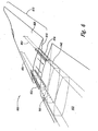
- FIG. 5 is an exploded isometric view of a derivative wing 500 illustrating one method for attaching an integrated tip extension 510 to a baseline wing 502 in accordance with an embodiment of the invention.
- the integrated tip extension 510 includes a plurality of first bolt holes 526 extending through an inboard end portion 515.
- the baseline wing 502 can similarly include a plurality of corresponding second bolt holes 524 extending through an opposing tip portion 506.
- a plurality of tension bolts or other suitable fasteners (not shown) passing through the first bolt holes 526 and the second bolt holes 524 can be used to fixedly attach the integrated tip extension 510 to the baseline wing 502.
- the baseline wing 502 and/or the integrated tip extension 510 can further include one or more access ports 528 to facilitate bolt installation. Because the foregoing manner of structural attachment lacks the strength of a direct spar-to-spar joint, this approach may be most suitable for integrated tip extensions having relatively short spans and/or for smaller aircraft having relatively lower gross weight requirements.
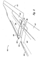
- FIG. 6 is an exploded isometric view of a derivative wing assembly 600 illustrating another method for structurally attaching an integrated tip extension 610 to a baseline wing 602 in accordance with an embodiment of the invention.
- the integrated tip extension 610 includes a tapered wing section 608 having a first front spar 651 and a first rear spar 652.
- the first front spar 651 is aligned with a corresponding second front spar 641 of the baseline wing 602, and the first rear spar 652 is similarly aligned with a second rear spar 642 of the baseline wing 602.
- a front spar extension 653 is fixedly attached to the first front spar 651, and extends beyond an inboard end portion 615 of the tapered wing section 608.
- a rear spar extension 654 is fixedly attached to the first rear spar 652, and extends beyond the inboard end portion 615.
- the front spar extension 653 sandwiches an adjacent portion of the second front spar 641
- the rear spar extension 654 sandwiches an adjacent portion of the second rear spar 642.
- a plurality of bolts or other suitable fasteners can be used to fixedly clamp the second front spar 641 in the front spar extension 653 and the second rear spar 642 in the rear spar extension 654. Attaching the spars in the foregoing manner creates a structurally efficient double-shear joint. In other embodiments, however, single shear joints can be used. Because of the relatively robust nature of the joint illustrated in Figure 6 , this method of attachment may be more suitable for use with integrated tip extensions of relatively long span and/or for use with baseline aircraft having relatively large structural loads.
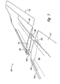
- Figure 7 is an exploded isometric view of a derivative wing assembly 700 having a baseline wing 702 and an integrated tip extension 710 configured in accordance with another embodiment of the invention.
- the integrated tip extension 710 includes a first leading edge control surface 766 and a first trailing edge control surface 767.
- the baseline wing 702 similarly includes a second leading edge control surface 756 and a second trailing edge control surface 757.
- the first leading edge control surface 766 and the second leading edge control surface 756 can be at least generally similar in structure and function to conventional leading edge slats or other types of movable leading edge devices for aerodynamic control.
- the first trailing edge control surface 767 and the second trailing edge control surface 757 can be at least generally similar in structure and function to conventional ailerons, trailing edge flaps, and/or other movable aerodynamic control devices.
- the integrated tip extension 710 can further include a first leading edge drive device 768 and a first trailing edge drive device 769 that extend beyond an inboard end portion 715.
- the first leading edge drive device 768 can include a drive shaft, torque rod, worm screw, and/or other device that rotates in a first direction for extension of the first leading edge control surface 766 and in a second direction for retraction of the first leading edge control surface 766.
- the first trailing edge drive device 769 can also include a drive shaft, torque rod, and/or other device for rotating, extending, and/or retracting the first trailing edge control surface 767.
- the first leading edge drive device 768 can be received by, or otherwise engaged with, a second leading edge drive device 758 associated with the second leading edge control surface 756.
- the first trailing edge device 769 can be received by, or otherwise engaged with, a second trailing edge drive device 759 associated with the second trailing edge control surface 757.
- the first leading edge control surface 766 can be operably coupled to the second leading edge control surface 756, and the first trailing edge control surface 767 can be operably coupled to the second trailing edge control surface 757, so that movement of the respective control surfaces is coordinated during flight.
- Figure 8 is an exploded isometric view of a derivative wing assembly 800 illustrating another method for operably coupling control surfaces on an integrated tip extension 810 to corresponding control surfaces on a baseline wing 802.
- the integrated tip extension 810 includes a first leading edge control surface 866 having a first socket 868, and a first trailing edge control surface 867 having a second socket 869.
- the baseline wing 802 includes a second leading edge control surface 856 having a first drive feature 858, and a second trailing edge surface 857 having a second drive feature 859.
- the first drive feature 858 is received in the first socket 868 to operably couple the first leading edge control surface 866 to the second leading edge control surface 856.
- the second drive feature 859 is received by the second socket 869 to operably couple the first trailing edge control surface to the second trailing edge control surface.
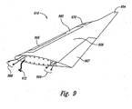
- FIG. 9 is an isometric view of an integrated tip extension 910 configured in accordance with another embodiment of the invention.
- the integrated tip extension 910 can be at least generally similar in structure and function to one or more of the integrated tip extensions described above.
- the integrated tip extension 910 can include a winglet 904 fixedly attached to a tapered wing section 908.
- the integrated tip extension 910 can also include a leading edge control surface 966 and a trailing edge control surface 967 which can be operably coupled to corresponding control surfaces on a baseline wing (not shown).
- the integrated tip extension 910 can further include a leading-edge deicing system 980 and/or one or more light assemblies 970.
- the light assemblies 970 can include navigation lights and/or position lights that are at least generally similar in structure and function to conventional navigation/position lights found on various types of commercial, military, and/or civilian aircraft.
- the integrated tip extension 910 of Figure 9 illustrates the "integrated" nature of the present invention.
- all, or at least many, of the systems necessary for operational use of the tip extension 910 e.g., the light assemblies 970, the deicing system 980, the winglet 904, etc.
- the integrated tip extension 910 can include one or more power cable connectors 972 for operably connecting the light assembly 970 and/or the deicing system 980 to the aircraft electrical system (not shown).
- the integrated tip extension 910 can further include one or more leading edge connectors 968 and one or more trailing edge connectors 969.
- the leading edge connectors 968 can be used to operably connect the leading edge control surface 966 to a corresponding aircraft control surface operating system (not shown).
- the trailing edge connectors 969 can be used to operably connect the trailing edge control surface 967 to the aircraft control surface operating system.
- the leading edge connectors 968 and the trailing edge connectors 969 can include one or more hydraulic connections.
- leading edge connectors 968 and/or the trailing edge connectors 969 can include one or more electrical connectors. While the various systems discussed above demonstrate the integrated nature of the illustrated embodiment, those of ordinary skill in the relevant art can appreciate that other integrated wingtip extensions configured in accordance with the present invention can include more, fewer, or different flight systems.
Abstract
Description
- The following disclosure relates generally to aircraft wings and, more particularly, to tip extensions for aircraft wings.
- Aircraft manufacturers often develop families of aircraft in which subsequent versions are able to carry more passengers and/or cargo than the earlier versions. Increasing the passenger and/or cargo capacity is typically accomplished by stretching the fuselage and/or increasing the wing area. One prior art approach for increasing wing area is illustrated in
Figures 1A-2B . -
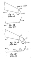
Figure 1A is a top view of abaseline wing assembly 100 configured in accordance with the prior art, andFigure 1B is a rear view looking forward at thebaseline wing assembly 100. Referring toFigures 1A and 1B together, thebaseline wing assembly 100 includes abaseline wing 102 and awinglet 104. Thewinglet 104 is fixedly attached to atip portion 106 of thebaseline wing 102. Although the chord length of thetip portion 106 is minimized for aerodynamic reasons, it is still long enough to allow human access for fixedly attaching thewinglet 104 to thebaseline wing 102. -
Figure 2A is a top view of aderivative wing assembly 200 configured in accordance with the prior art, andFigure 2B is a rear view looking forward at thederivative wing assembly 200. Referring toFigures 2A and 2B together, thederivative wing assembly 200 includes a constant-chord tip extension 208 for increasing the wing area of thebaseline wing 102. The constant-chord tip extension 208 includes anoutboard end portion 206 spaced apart from an inboard end portion 205. The inboard end portion 205 is fixedly attached to thetip portion 106 of thebaseline wing 102, and awinglet 204 is fixedly attached to theoutboard end portion 206. Thewinglet 204 can be at least generally similar in structure and function to thewinglet 104 illustrated inFigures 1A and 1B . - Although it may be advantageous from an aerodynamic standpoint to taper the constant-
chord tip extension 208, this is not possible from an assembly standpoint because the resulting tip chord would be too small to accommodate human access for attachment of thewinglet 204. For this reason, the chord length of theoutboard end portion 206 is the same as the chord length of the inboard end portion 205 (hence the term "constant-chord"). One downside of this approach, however, is that the resulting planform of thederivative wing assembly 200 is not optimized for aerodynamic performance. - Document
US-A-5407153 , which discloses an airplane wing modification kit including a wingtip extension, is considered the closest prior art showing all the features of the preamble of the independent claims 1 and 6. - This summary is provided for the benefit of the reader only, and is not intended to limit the invention as set forth by the claims.
- The present invention is directed generally to integrated wingtip extensions for use with jet transport aircraft and other types of aircraft, as defined by the features of claim 1. A wingtip extension configured in accordance with one aspect of the invention includes a tapered wing section and a winglet. The tapered wing section has an inboard end portion with a first chord length and an outboard end portion with a second chord length that is less than the first chord length. The winglet is fixedly attached to the outboard end portion of the tapered wing section.
- In one embodiment, the outboard end portion of the tapered wing section can be spaced apart from the inboard end portion by a spanwise dimension that is at least as long as the second chord length. In another embodiment, the tapered wing section can further include a first trailing edge portion that is configured to be aligned with a second trailing edge portion of an aircraft wing when the tapered wing section is fixedly attached to the aircraft wing. In a further embodiment, the tapered wing section and the winglet can be integrally formed from composite materials.
- Another aspect of the invention is directed to a method for increasing the wing area of a baseline aircraft having a baseline wing, as defined by the features of claim 6. The method includes fixedly attaching an inboard end portion of a tapered wing section to a tip portion of the baseline wing, and fixedly attaching a winglet to an outboard end portion of the tapered wing section. The inboard end portion has a first chord length and the outboard end portion has a second chord length that is less than the first chord length. In one embodiment, fixedly attaching a winglet to the outboard end portion of the tapered wing section can include manufacturing the winglet and the tapered wing section together as an integral composite structure.
- A derivative aircraft configured in accordance with another aspect of the invention includes a baseline wing from a baseline aircraft, a tapered wing section, and a winglet. The baseline wing has a first tip portion spaced apart from a first root portion. The tapered wing section has a second tip portion spaced apart from a second root portion. The second root portion has a first chord length and the second tip portion has a second chord length that is less than the first chord length. The derivative aircraft further includes means for fixedly attaching the second root portion of the tapered wing section to the first tip portion of the baseline wing. In addition, the derivative aircraft also includes means for fixedly attaching the winglet to the second tip portion of the tapered wing section. In one embodiment, the means for fixedly attaching the winglet to the second tip portion of the tapered wing section include means for manufacturing the winglet and the tapered wing section together as an integral composite structure.
-
-
Figures 1A and 1B are top and rear views, respectively, of a baseline wing assembly configured in accordance with the prior art. -
Figures 2A and 2B are top and rear views, respectively, of a derivative wing assembly configured in accordance with the prior art. -
Figures 3A and 3B are top and rear views, respectively, of a derivative wing assembly configured in accordance with an embodiment of the invention. -
Figures 4A and 4B are top views of derivative wing assemblies configured in accordance with other embodiments of the invention. -
Figure 5 is an exploded isometric view of a wing and a wingtip extension illustrating a structural connection configured in accordance with an embodiment of the invention. -
Figure 6 is an exploded isometric view of a wing and a wingtip extension illustrating a structural connection configured in accordance with another embodiment of the invention. -
Figure 7 is an exploded isometric view of a wing and a wingtip extension illustrating a control surface connection configured in accordance with an embodiment of the invention. -
Figure 8 is an exploded isometric view of a wing and a wingtip extension illustrating a control surface connection configured in accordance with another embodiment of the invention. -
Figure 9 is an isometric view of an integrated wingtip extension and associated electrical and/or hydraulic system connectors configured in accordance with an embodiment of the invention. - The following disclosure describes systems and methods for increasing the wing area on various types of baseline aircraft. Certain details are set forth in the following description to provide a thorough understanding of various embodiments of the invention. Other details describing well-known structures and systems often associated with aircraft, aircraft wings, and/or winglets are not set forth below, however, to avoid unnecessarily obscuring the description of the various embodiments of the invention.
- Many of the details, dimensions, angles and other features shown in the Figures are merely illustrative of particular embodiments of the invention. Accordingly, other embodiments can have other details, dimensions, angles and features without departing from the spirit or scope of the present invention. Furthermore, additional embodiments of the invention can be practiced without several of the details described below.
- In the Figures, identical reference numbers identify identical or at least generally similar elements. To facilitate the discussion of any particular element, the most significant digit or digits of any reference number refer to the Figure in which that element is first introduced. For example,
element 308 is first introduced and discussed with reference toFigure 3 . -
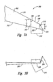
Figures 3A and 3B are top and rear views, respectively, of aderivative wing assembly 300 having an integratedtip extension 310 configured in accordance with an embodiment of the invention. Referring toFigures 3A and 3B together, the integratedtip extension 310 includes atapered wing section 308 and awinglet 304. Thetapered wing section 308 includes anoutboard end portion 316 spaced apart from aninboard end portion 315 by a spanwise dimension S. Theinboard end portion 315 has a first chord length L1 and theoutboard end portion 316 has a second chord length L2 that is less than the first chord length L1. In the illustrated embodiment, the spanwise dimension S is at least as long as the second chord length L2. Theinboard end portion 315 is fixedly attached to atip portion 306 of abaseline wing 302. Thewinglet 304 is fixedly attached to theoutboard end portion 316. As discussed in greater detail below, tapering theintegrated tip extension 310 from theinboard end portion 315 to theoutboard end portion 316 as illustrated inFigure 3A can increase the aerodynamic efficiency of thederivative wing assembly 300 over the prior artderivative wing assembly 200 described above with reference toFigures 2A and 2B . - The tapered
wing section 308 further includes a firstleading edge portion 321 and a firsttrailing edge portion 322. Thebaseline wing 302 further includes a secondleading edge portion 311 and a secondtrailing edge portion 312. In one aspect of this embodiment, the firstleading edge portion 321 is at least approximately aligned with the secondleading edge portion 311, and the firsttrailing edge portion 322 is at least approximately aligned with the secondtrailing edge portion 312, when the taperedwing section 308 is fixedly attached to thebaseline wing 302 as illustrated inFigure 3A . As described in greater detail below, other embodiments of the invention can include wingtip extensions where one or both of the leading and trailing edges are not aligned with the corresponding leading and trailing edges of the baseline wing. - Although the
winglet 304 is illustrated inFigure 3B extending upwardly relative to thebaseline wing 302, in other embodiments, thewinglet 304 can extend in other directions relative to thebaseline wing 302. For example, in one embodiment, thewinglet 304 can extend at least approximately downwardly relative to thebaseline wing 302. In another embodiment, thewinglet 304 can extend outwardly in alignment with thebaseline wing 302. Accordingly, aspects of the present invention are not limited to the relative positioning of thewinglet 304, but extend to all winglet and/or wingtip extensions falling within the scope of the claims. - The
integrated tip extension 310 can be manufactured in a number of different ways using a number of different materials. In one embodiment, for example, theintegrated tip extension 310 can be manufactured from aluminum and/or other lightweight metals using "conventional" aircraft construction techniques. In another embodiment, thewinglet 304 and the taperedwing section 308 can be manufactured concurrently from fiber-reinforced resin materials (e.g., graphite/epoxy materials) and/or other composite materials using suitable composite manufacturing techniques. - With either of these approaches, it may be advantageous to manufacture the tapered
wing section 308 and thewinglet 304 together as a single unit rather than having to mechanically or otherwise join the two parts together after manufacturing. Doing so eliminates the need for human access to manually attach thewinglet 304 to the taperedwing section 308. As a result, the second chord length L2 of theoutboard end portion 316 can be reduced beyond the first chord length L1 of theinboard end portion 315 to maintain the taper of thebaseline wing 302 or to otherwise optimize the planform of thederivative wing assembly 300 as desired. - As mentioned above, one feature of the
derivative wing assembly 300 is that the taperedwing section 308 can be shaped as desired to optimize wing planform. One advantage of this feature over conventional tip extensions is that it can increase the aerodynamic efficiency of the overall wing configuration. For example, the prior artderivative wing assembly 200 discussed above with reference toFigures 2A and 2B is constrained to a constant-chord wing section 208 which does not maintain the taper of thebaseline wing 102. As a result, the drag characteristics of the prior artderivative wing assembly 200 suffer. In contrast, because theintegrated tip extension 310 of the present invention is not constrained to a constant-chord planform, theintegrated tip extension 310 can be shaped for improved aerodynamic characteristics while at the same time increasing the wing area to accommodate a stretched fuselage and/or an increased passenger load. -
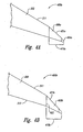
Figures 4A and 4B are top views ofderivative wing assemblies Figure 4A , thederivative wing assembly 400a includes anintegrated tip extension 410a composed of atapered wing section 408a and a winglet 404a. Theintegrated tip extension 410a can be at least generally similar in structure and function to theintegrated tip extension 310 described above with reference toFigures 3A and 3B . One difference, however, is that the taperedwing section 408a includes a first leading edge portion 421 a that is swept aft relative to the secondleading edge portion 311 of thebaseline wing 302. - Referring next to
Figure 4B , thederivative wing assembly 400b includes anintegrated tip extension 410b that can be at least generally similar in structure and function to theintegrated tip extension 410a illustrated inFigure 4A . One difference, however, is that theintegrated tip extension 410b includes a taperedwing section 408b having a firstleading edge portion 421 b that is swept aft relative to the secondleading edge portion 311 of thebaseline wing 302, and a firsttrailing edge portion 422 that is swept aft relative to the secondtrailing edge portion 312 of thebaseline wing 302. -
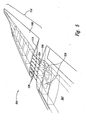
Figure 5 is an exploded isometric view of aderivative wing 500 illustrating one method for attaching anintegrated tip extension 510 to abaseline wing 502 in accordance with an embodiment of the invention. In this embodiment, theintegrated tip extension 510 includes a plurality of first bolt holes 526 extending through aninboard end portion 515. Thebaseline wing 502 can similarly include a plurality of corresponding second bolt holes 524 extending through an opposingtip portion 506. A plurality of tension bolts or other suitable fasteners (not shown) passing through the first bolt holes 526 and the second bolt holes 524 can be used to fixedly attach theintegrated tip extension 510 to thebaseline wing 502. Thebaseline wing 502 and/or theintegrated tip extension 510 can further include one ormore access ports 528 to facilitate bolt installation. Because the foregoing manner of structural attachment lacks the strength of a direct spar-to-spar joint, this approach may be most suitable for integrated tip extensions having relatively short spans and/or for smaller aircraft having relatively lower gross weight requirements. -
Figure 6 is an exploded isometric view of aderivative wing assembly 600 illustrating another method for structurally attaching anintegrated tip extension 610 to abaseline wing 602 in accordance with an embodiment of the invention. In this embodiment, theintegrated tip extension 610 includes a taperedwing section 608 having a firstfront spar 651 and a firstrear spar 652. The firstfront spar 651 is aligned with a corresponding secondfront spar 641 of thebaseline wing 602, and the firstrear spar 652 is similarly aligned with a secondrear spar 642 of thebaseline wing 602. Afront spar extension 653 is fixedly attached to the firstfront spar 651, and extends beyond aninboard end portion 615 of the taperedwing section 608. Similarly, arear spar extension 654 is fixedly attached to the firstrear spar 652, and extends beyond theinboard end portion 615. When theinboard end portion 615 of the taperedwing section 608 is butted against a tip portion 606 of thebaseline wing 602, thefront spar extension 653 sandwiches an adjacent portion of the secondfront spar 641, and therear spar extension 654 sandwiches an adjacent portion of the secondrear spar 642. Then, a plurality of bolts or other suitable fasteners (not shown) can be used to fixedly clamp the secondfront spar 641 in thefront spar extension 653 and the secondrear spar 642 in therear spar extension 654. Attaching the spars in the foregoing manner creates a structurally efficient double-shear joint. In other embodiments, however, single shear joints can be used. Because of the relatively robust nature of the joint illustrated inFigure 6 , this method of attachment may be more suitable for use with integrated tip extensions of relatively long span and/or for use with baseline aircraft having relatively large structural loads. -
Figure 7 is an exploded isometric view of aderivative wing assembly 700 having abaseline wing 702 and anintegrated tip extension 710 configured in accordance with another embodiment of the invention. In this embodiment, theintegrated tip extension 710 includes a first leadingedge control surface 766 and a first trailingedge control surface 767. Thebaseline wing 702 similarly includes a second leadingedge control surface 756 and a second trailingedge control surface 757. The first leadingedge control surface 766 and the second leadingedge control surface 756 can be at least generally similar in structure and function to conventional leading edge slats or other types of movable leading edge devices for aerodynamic control. Similarly, the first trailingedge control surface 767 and the second trailingedge control surface 757 can be at least generally similar in structure and function to conventional ailerons, trailing edge flaps, and/or other movable aerodynamic control devices. - The
integrated tip extension 710 can further include a first leadingedge drive device 768 and a first trailingedge drive device 769 that extend beyond aninboard end portion 715. In one embodiment, the first leadingedge drive device 768 can include a drive shaft, torque rod, worm screw, and/or other device that rotates in a first direction for extension of the first leadingedge control surface 766 and in a second direction for retraction of the first leadingedge control surface 766. Similarly, the first trailingedge drive device 769 can also include a drive shaft, torque rod, and/or other device for rotating, extending, and/or retracting the first trailingedge control surface 767. - When the
integrated tip extension 710 is fixedly attached to thebaseline wing 702, the first leadingedge drive device 768 can be received by, or otherwise engaged with, a second leadingedge drive device 758 associated with the second leadingedge control surface 756. Similarly, the firsttrailing edge device 769 can be received by, or otherwise engaged with, a second trailingedge drive device 759 associated with the second trailingedge control surface 757. In the foregoing manner, the first leadingedge control surface 766 can be operably coupled to the second leadingedge control surface 756, and the first trailingedge control surface 767 can be operably coupled to the second trailingedge control surface 757, so that movement of the respective control surfaces is coordinated during flight. -
Figure 8 is an exploded isometric view of aderivative wing assembly 800 illustrating another method for operably coupling control surfaces on anintegrated tip extension 810 to corresponding control surfaces on abaseline wing 802. In this embodiment, theintegrated tip extension 810 includes a first leadingedge control surface 866 having afirst socket 868, and a first trailingedge control surface 867 having asecond socket 869. Thebaseline wing 802 includes a second leadingedge control surface 856 having afirst drive feature 858, and a secondtrailing edge surface 857 having asecond drive feature 859. - When the
integrated tip extension 810 is fixedly attached to thebaseline wing 802, thefirst drive feature 858 is received in thefirst socket 868 to operably couple the first leadingedge control surface 866 to the second leadingedge control surface 856. Similarly, thesecond drive feature 859 is received by thesecond socket 869 to operably couple the first trailing edge control surface to the second trailing edge control surface. This method of operably coupling control surfaces together may be advantageous for use with integrated tip devices having relatively short-spans. -
Figure 9 is an isometric view of anintegrated tip extension 910 configured in accordance with another embodiment of the invention. Theintegrated tip extension 910 can be at least generally similar in structure and function to one or more of the integrated tip extensions described above. For example, theintegrated tip extension 910 can include awinglet 904 fixedly attached to atapered wing section 908. Further, theintegrated tip extension 910 can also include a leadingedge control surface 966 and a trailingedge control surface 967 which can be operably coupled to corresponding control surfaces on a baseline wing (not shown). In addition, theintegrated tip extension 910 can further include a leading-edge deicing system 980 and/or one or morelight assemblies 970. Thelight assemblies 970 can include navigation lights and/or position lights that are at least generally similar in structure and function to conventional navigation/position lights found on various types of commercial, military, and/or civilian aircraft. - The
integrated tip extension 910 ofFigure 9 illustrates the "integrated" nature of the present invention. For example, all, or at least many, of the systems necessary for operational use of the tip extension 910 (e.g., thelight assemblies 970, thedeicing system 980, thewinglet 904, etc.) are pre-installed during the manufacturing phase. This enables thetip extension 910 to be retrofitted or otherwise installed on a baseline aircraft wing relatively quickly with a minimum of downtime or expense. To facilitate installation, theintegrated tip extension 910 can include one or morepower cable connectors 972 for operably connecting thelight assembly 970 and/or thedeicing system 980 to the aircraft electrical system (not shown). In addition, theintegrated tip extension 910 can further include one or moreleading edge connectors 968 and one or moretrailing edge connectors 969. Theleading edge connectors 968 can be used to operably connect the leadingedge control surface 966 to a corresponding aircraft control surface operating system (not shown). Similarly, the trailingedge connectors 969 can be used to operably connect the trailingedge control surface 967 to the aircraft control surface operating system. By way of example, if the aircraft control surface operating system includes a hydraulic system, then theleading edge connectors 968 and the trailingedge connectors 969 can include one or more hydraulic connections. Alternatively, if the aircraft control surface operating system utilizes electrical power for control surface actuation, then theleading edge connectors 968 and/or the trailingedge connectors 969 can include one or more electrical connectors. While the various systems discussed above demonstrate the integrated nature of the illustrated embodiment, those of ordinary skill in the relevant art can appreciate that other integrated wingtip extensions configured in accordance with the present invention can include more, fewer, or different flight systems. - From the foregoing, it will be appreciated that specific embodiments of the invention have been described herein for purposes of illustration, but that various modifications may be made without deviating from the spirit and scope of the invention. For example, aspects of the invention described in the context of particular embodiments may be combined or eliminated in other embodiments. Further, while advantages associated with certain embodiments of the invention have been described in the context of those embodiments, other embodiments may also exhibit such advantages, and not all embodiments need necessarily exhibit such advantages to fall within the scope of the invention. Accordingly, the invention is not limited, except as by the appended claims.
Claims (11)
- A wingtip extension (310) for use with an aircraft wing (302), the wingtip extension (310) comprising:a tapered wing section (308), the tapered wing section (308) having an inboard end portion (315) with a first chord length (L1) and an outboard end portion (316) with a second chord length (L2) that is less than the first chord length (L1), wherein the inboard end portion (315) is configured to be fixedly attached to a tip portion (306) of the aircraft wing (302); anda winglet (304) fixedly attached to the outboard end portion (316) of the taperedwing section (308).characterized in that the outboard end portion (316) of the tapered wing section (308) is spaced apart from the inboard end portion (315) of the tapered wing section (308) by a spanwise dimension that is at least as long as the second chord length (L2).
- The wingtip extension (310) according to claim 1 , characterized in that the tapered wing section (308) further includes a first leading edge portion (321) and a first trailing edge portion (322), and in that the aircraft wing (302) further includes a second leading edge portion (311) and a second trailing edge portion (312), wherein the first leading edge portion of the tapered wing section (308) is configured to be aligned with or sweep aft of the second leading edge portion of the aircraft wing (302), and wherein the first trailing edge portion of the tapered wing section (308) is configured to be aligned with or sweep aft of the second trailing edge portion of the aircraft wing (302), when the inboard end portion (315) of the tapered wing section (308) is fixedly attached to the tip portion (306) of the aircraft wing (302).
- The wingtip extension (310) according to any of claims 1 to 2, characterized in that the tapered wing section (308) further includes a first movable control surface (766) and the aircraft wing (302) further includes a second movable control surface (756), and wherein the first movable control surface is configured to be operably coupled to the second movable control surface when the inboard end portion (315) of the tapered wing section (308) is fixedly attached to the tip portion (306) of the aircraft wing (302).
- The wingtip extension (310) according to any of claims 1 to 3, characterized in that the tapered wing section (308) further includes a first navigation light system and the aircraft wing (302) further includes a second navigation light system, and wherein the first navigation light system is configured to be operably connected to the second navigation light system when the inboard end portion (315) of the tapered wing section (308) is fixedly attached to the tip portion (306) of the aircraft wing (302).
- The wingtip extension (310) according to any of claims 1 to 4, characterized in that the tapered wing section and the winglet are integrally formed from composite materials.
- A method for increasing the wing area of a baseline aircraft having a baseline wing (302), the method comprising:fixedly attaching an inboard end portion (315) of a tapered wing section (308) to a tip portion (306) of the baseline wing (302), wherein the tapered wing section (308) includes an outboard end portion (316) spaced apart from the inboard end portion (315), the inboard end portion (315) having a first chord length and the outboard end portion (316) having a second chord length that is less than the first chord length; andfixedly attaching a winglet (304) to the outboard end portion (316) of the tapered wing section (308), wherein the outboard end portion (316) of the tapered wing section (308) is spaced apart from the inboard end portion (315) of the tapered wing section (308) by a spanwise dimension that is at least as long as the second chord length (L2).
- The method of claim 6, characterized in that fixedly attaching a winglet (304) to the outboard end portion (316) of the tapered wing section (308) includes manufacturing the winglet and the tapered wing section (308) together as an integral composite structure.
- The method of claim 7, characterized in that fixedly attaching an inboard end portion (315) of a tapered wing section (308) to a tip portion of the baseline wing (302) includes:structurally attaching a first front spar (651) carried by the tapered wing section (308) to a second front spar (641) carried by the baseline wing (302); andstructurally attaching a first rear spar (652) carried by the tapered wing section (308) to a second rear spar (642) carried by the baseline wing (302).
- The method of any of claims 6 to 8, characterized by operably coupling a first movable control surface carried by the tapered wing section to a second movable control surface carried by the baseline wing.
- The method of any of claims 6 to 9, characterized in that the baseline wing includes a second winglet fixedly attached to its tip portion, and in that the method comprises removing the second winglet from the tip portion of the baseline wing before fixedly attaching the inboard end portion of the tapered wing section to the tip portion of the baseline wing.
- A derivative aircraft system comprising:a baseline wing from a baseline aircraft, the baseline wing having a tip portion spaced apart from a root portion; anda wingtip extension (310) according to any of claims 1 to 5 having its inboard end portion (315) fixedly attached to the tip portion (306) of the baseline wing (302).
Applications Claiming Priority (2)
| Application Number | Priority Date | Filing Date | Title |
|---|---|---|---|
| US11/187,443 US8544800B2 (en) | 2005-07-21 | 2005-07-21 | Integrated wingtip extensions for jet transport aircraft and other types of aircraft |
| PCT/US2006/024739 WO2007018785A1 (en) | 2005-07-21 | 2006-06-26 | Integrated wingtip extensions for jet transport aircraft and other types of aircraft |
Publications (2)
| Publication Number | Publication Date |
|---|---|
| EP1934090A1 EP1934090A1 (en) | 2008-06-25 |
| EP1934090B1 true EP1934090B1 (en) | 2009-08-05 |
Family
ID=37069684
Family Applications (1)
| Application Number | Title | Priority Date | Filing Date |
|---|---|---|---|
| EP06773970A Active EP1934090B1 (en) | 2005-07-21 | 2006-06-26 | Integrated wingtip extension and method of increasing the wing area of a baseline aircraft |
Country Status (8)
| Country | Link |
|---|---|
| US (1) | US8544800B2 (en) |
| EP (1) | EP1934090B1 (en) |
| JP (1) | JP5230413B2 (en) |
| CN (2) | CN103661930B (en) |
| AT (1) | ATE438561T1 (en) |
| CA (1) | CA2613680C (en) |
| DE (1) | DE602006008332D1 (en) |
| WO (1) | WO2007018785A1 (en) |
Families Citing this family (85)
| Publication number | Priority date | Publication date | Assignee | Title |
|---|---|---|---|---|
| US7699261B2 (en) * | 2007-03-05 | 2010-04-20 | Lockheed Martin Corporation | Small unmanned airborne vehicle airframe |
| US7900876B2 (en) * | 2007-08-09 | 2011-03-08 | The Boeing Company | Wingtip feathers, including forward swept feathers, and associated aircraft systems and methods |
| US20090084904A1 (en) * | 2007-10-02 | 2009-04-02 | The Boeing Company | Wingtip Feathers, Including Paired, Fixed Feathers, and Associated Systems and Methods |
| DE102007059455A1 (en) * | 2007-12-10 | 2009-06-25 | Airbus Deutschland Gmbh | Wingtip extension to reduce wake turbulences on airplanes |
| US8167569B2 (en) | 2007-12-21 | 2012-05-01 | General Electric Company | Structure and method for self-aligning rotor blade joints |
| US20090172776A1 (en) * | 2007-12-31 | 2009-07-02 | Petr Makagon | Method and System for Establishing and Managing Trust Metrics for Service Providers in a Federated Service Provider Network |
| US8128035B2 (en) * | 2008-04-15 | 2012-03-06 | The Boeing Company | Winglets with recessed surfaces, and associated systems and methods |
| US7975965B2 (en) * | 2008-05-13 | 2011-07-12 | The Boeing Company | Wing tip joint in airfoils |
| US9302766B2 (en) * | 2008-06-20 | 2016-04-05 | Aviation Partners, Inc. | Split blended winglet |
| WO2009155584A1 (en) | 2008-06-20 | 2009-12-23 | Aviation Partners, Inc. | Curved wing tip |
| US8328516B2 (en) * | 2009-09-29 | 2012-12-11 | General Electric Company | Systems and methods of assembling a rotor blade extension for use in a wind turbine |
| US20110127383A1 (en) * | 2009-12-01 | 2011-06-02 | Guida Associates Consulting, Inc. | Active winglet |
| US9162755B2 (en) | 2009-12-01 | 2015-10-20 | Tamarack Aerospace Group, Inc. | Multiple controllable airflow modification devices |
| WO2011127938A1 (en) | 2010-04-12 | 2011-10-20 | Airbus Operations Gmbh | Fixed wing of an aircraft |
| GB201011843D0 (en) * | 2010-07-14 | 2010-09-01 | Airbus Operations Ltd | Wing tip device |
| US8382041B1 (en) * | 2010-08-04 | 2013-02-26 | The United States Of America As Represented By The Secretary Of The Air Force | Rakelet |
| DE102010040596A1 (en) * | 2010-09-10 | 2012-03-15 | Aloys Wobben | Removable rotor blade tip |
| DE102010048266A1 (en) * | 2010-10-12 | 2012-04-12 | Airbus Operations Gmbh | Wing with a flow fence and plane with such wings |
| GB201018185D0 (en) * | 2010-10-28 | 2010-12-08 | Airbus Operations Ltd | Wing tip device attachment apparatus and method |
| CN102167152B (en) * | 2011-03-11 | 2014-04-16 | 中国商用飞机有限责任公司 | Airplane wingtip device with aligned front edge |
| CN102167153B (en) * | 2011-03-11 | 2014-04-16 | 中国商用飞机有限责任公司 | Airplane wingtip device with aligned back edges |
| EP2684797B1 (en) * | 2011-03-11 | 2019-06-26 | Commercial Aircraft Corporation Of China Ltd | Airplane wingtip device |
| CN102167154B (en) * | 2011-03-11 | 2014-04-16 | 中国商用飞机有限责任公司 | Airplane wingtip device |
| GB201105104D0 (en) * | 2011-03-28 | 2011-05-11 | Airbus Operations Ltd | Joint |
| DK3372493T3 (en) * | 2011-06-09 | 2019-12-09 | Aviation Partners Inc | THE PART-SHAPED MIXED WINGLET |
| GB201110493D0 (en) | 2011-06-21 | 2011-08-03 | Airbus Operations Ltd | Aircraft wing with wing tip device |
| WO2013070296A2 (en) * | 2011-08-19 | 2013-05-16 | Aerovironment, Inc. | Aircraft system for reduced observer visibility |
| US8936219B2 (en) | 2012-03-30 | 2015-01-20 | The Boeing Company | Performance-enhancing winglet system and method |
| GB201209697D0 (en) * | 2012-05-31 | 2012-07-18 | Airbus Uk Ltd | Method of coupling aerofoil surface structures and an aerofoil assembly |
| ES2799904T3 (en) * | 2012-10-03 | 2020-12-22 | Airbus Operations Sl | End hull of a horizontal bearing surface |
| US9567066B2 (en) * | 2013-02-05 | 2017-02-14 | Tamarack Aerospace Group, Inc. | Controllable airflow modification device periodic load control |
| GB201307066D0 (en) * | 2013-04-18 | 2013-05-29 | Airbus Operations Ltd | Winglet and braided composite spar |
| US9452825B2 (en) * | 2013-04-19 | 2016-09-27 | The Boeing Company | Winglet attach fitting for attaching a split winglet to a wing |
| WO2015050617A2 (en) * | 2013-07-15 | 2015-04-09 | Design Intelligence Incorporated, LLC | Unmanned aerial vehicle (uav) with inter-connecting wing sections |
| US10562613B2 (en) * | 2013-12-04 | 2020-02-18 | Tamarack Aerospace Group, Inc. | Adjustable lift modification wingtip |
| US9738375B2 (en) * | 2013-12-05 | 2017-08-22 | The Boeing Company | One-piece composite bifurcated winglet |
| US9511850B2 (en) | 2014-04-12 | 2016-12-06 | The Boeing Company | Wing tip device for an aircraft wing |
| US20150369211A1 (en) * | 2014-06-19 | 2015-12-24 | General Electric Company | Wind blade tip joint |
| EP3130534B1 (en) * | 2014-09-30 | 2020-03-18 | Commercial Aircraft Corporation Of China Ltd | Airplane wing assembly |
| GB2532238A (en) * | 2014-11-12 | 2016-05-18 | Airbus Operations Ltd | An aircraft with a wing tip comprising a fuel pod |
| GB2536447A (en) * | 2015-03-17 | 2016-09-21 | Airbus Operations Ltd | Load transfer apparatus for transferring loads in an aircraft structure |
| GB2536448A (en) * | 2015-03-17 | 2016-09-21 | Airbus Operations Ltd | A connector between two aircraft components, such as a wing and wing tip device |
| JP6114337B2 (en) * | 2015-05-27 | 2017-04-12 | エアバス オペレーションズ ゲーエムベーハーAirbus Operations GmbH | Method of constructing aircraft wing, aircraft wing configuration and aircraft comprising wing configuration |
| GB2547957A (en) * | 2016-05-24 | 2017-09-06 | Airbus Operations Ltd | Winglet |
| GB2551311A (en) * | 2016-05-24 | 2017-12-20 | Airbus Operations Ltd | Winglet |
| GB2551708A (en) * | 2016-06-23 | 2018-01-03 | Airbus Operations Ltd | Winglet |
| EP3263446B1 (en) * | 2016-06-29 | 2019-06-05 | Goodrich Actuation Systems Limited | Folding wing |
| EP3269635A1 (en) * | 2016-07-12 | 2018-01-17 | The Aircraft Performance Company UG | Airplane wing |
| CN106005369B (en) * | 2016-07-24 | 2018-07-03 | 尹鸿俊 | A kind of unmanned plane |
| US10710702B2 (en) * | 2016-08-12 | 2020-07-14 | Aviation Partners, Inc. | Shape adaptive airfoil |
| US10495058B2 (en) * | 2017-02-21 | 2019-12-03 | General Electric Company | Joint assembly for rotor blade segments of a wind turbine |
| US10830214B2 (en) * | 2017-03-22 | 2020-11-10 | General Electric Company | Method for securing a lightning receptor cable within a segmented rotor blade |
| US10647406B2 (en) * | 2017-06-01 | 2020-05-12 | The Boeing Company | Closed-angle composite airfoil spar and method of fabricating the same |
| US11046434B2 (en) * | 2017-09-19 | 2021-06-29 | The Boeing Company | Methods and apparatus to align and secure aircraft |
| WO2019061100A1 (en) * | 2017-09-27 | 2019-04-04 | 深圳市大疆创新科技有限公司 | Wing assembly and unmanned aerial vehicle |
| GB2568229B (en) * | 2017-10-19 | 2020-01-29 | Airbus Operations Ltd | An aircraft assembly including a wingtip device |
| GB201719806D0 (en) * | 2017-11-29 | 2018-01-10 | Airbus Operations Ltd | Retrofit flight control surface |
| EP3492374A3 (en) | 2017-11-29 | 2019-09-04 | Airbus Operations Limited | Retrofit flight control surface |
| EP3511243B1 (en) * | 2018-01-15 | 2021-12-29 | The Aircraft Performance Company GmbH | Airplane wing |
| EP3774527A1 (en) | 2018-04-02 | 2021-02-17 | Aero Design Labs, Inc. | Elliptical wing tip and method of fabricating same |
| CN108454822A (en) * | 2018-04-28 | 2018-08-28 | 成都航空职业技术学院 | A kind of small swing device of replaceable and its change method |
| CN110550187A (en) * | 2018-06-01 | 2019-12-10 | 空中客车德国运营有限责任公司 | wing device for aircraft and aircraft |
| US10830207B2 (en) | 2018-08-28 | 2020-11-10 | General Electric Company | Spar configuration for jointed wind turbine rotor blades |
| GB2576929A (en) * | 2018-09-07 | 2020-03-11 | Airbus Operations Ltd | A wing tip device |
| WO2020086080A1 (en) | 2018-10-25 | 2020-04-30 | General Electric Company | Spar cap configuration for a jointed wind turbine blade |
| US11162476B2 (en) * | 2018-10-30 | 2021-11-02 | General Electric Company | Wind turbine rotor blade pre-staged for retrofitting with a replacement blade tip segment |
| DK3874155T3 (en) | 2018-10-31 | 2023-10-23 | Gen Electric | ARTICULATED WIND TURBINE ROTOR BLADE WITH VARIOUS MATERIAL COMBINATIONS ALONG ITS SPAN FOR STUD REINFORCEMENT |
| BR112021007402A2 (en) | 2018-11-01 | 2021-08-03 | General Electric Company | rotor blade for a wind turbine and method of joining first and second blade segments of a wind turbine rotor blade |
| JP7430299B2 (en) | 2018-11-01 | 2024-02-13 | ゼネラル エレクトリック レノバブレス エスパーニャ, エセ.エレ. | Method for installing and retaining bushings in the support blocks of joints of rotor blades |
| EP3874140A1 (en) | 2018-11-01 | 2021-09-08 | General Electric Company | Scarf connection for a wind turbine rotor blade |
| EP3874141A1 (en) | 2018-11-01 | 2021-09-08 | General Electric Company | Span-wise extending pin for joining rotor blade segments |
| JP7214859B2 (en) | 2018-11-01 | 2023-01-30 | ゼネラル・エレクトリック・カンパニイ | Compliant structure for jointed rotor blades |
| US11767819B2 (en) | 2018-11-01 | 2023-09-26 | General Electric Company | Spacer material, for reducing a bond gap between a beam structure and a blade shell of a segmented rotor blade |
| AU2018452334A1 (en) | 2018-12-11 | 2021-07-08 | General Electric Renovables España, S.L. | Method for manufacturing a structural component of a blade segment for a rotor blade of a wind turbine |
| EP3894193A1 (en) | 2018-12-11 | 2021-10-20 | General Electric Company | Method for manufacturing a structural component of a blade segment for a rotor blade of a wind turbine |
| EP3894690A1 (en) | 2018-12-11 | 2021-10-20 | General Electric Company | Beam structure for a segmented rotor blade having a transitioning shape |
| AU2018452333A1 (en) | 2018-12-11 | 2021-07-08 | General Electric Renovables España, S.L. | Method for manufacturing a hollow composite structure, particularly a spar beam for a wind turbine rotor blade, and an associated mandrel |
| US11614069B2 (en) | 2018-12-13 | 2023-03-28 | General Electric Company | Jointed rotor blade having a chord-wise extending pin supported via one or more structural members |
| US11802543B2 (en) | 2018-12-19 | 2023-10-31 | General Electric Company | Jointed rotor blade having internal support structure with varying fiber orientation for pin reinforcement |
| WO2020131067A1 (en) | 2018-12-20 | 2020-06-25 | General Electric Company | Jointed wind turbine rotor blade having spar cap constructed of varying forms of materials along its span |
| WO2020180601A1 (en) * | 2019-03-01 | 2020-09-10 | General Electric Company | Jointed wind turbine rotor blade with chord-wise extending pin bushings designed to minimize chord-wise gap |
| GB2583465A (en) * | 2019-04-18 | 2020-11-04 | Airbus Operations Ltd | Wingtip device attachment |
| CN112373673B (en) * | 2020-09-25 | 2023-09-26 | 哈尔滨工业大学 | Flow control method of leading edge biconvex structure for improving performance of biconvex wing section |
| GB2619276A (en) * | 2022-05-25 | 2023-12-06 | Airbus Operations Ltd | Wing structures for supporting wing tip devices |
| US11891171B1 (en) * | 2023-06-12 | 2024-02-06 | Faruk Dizdarevic | Aircraft wing with tiplet |
Family Cites Families (64)
| Publication number | Priority date | Publication date | Assignee | Title |
|---|---|---|---|---|
| DE634884C (en) | 1936-09-05 | Hamburger Flugzeugbau G M B H | Carrying spar for airplanes consisting of approximately semicircular shells | |
| US1354677A (en) | 1918-04-08 | 1920-10-05 | Melville W Mix | Knockdown airplane-fuselage and process therefor |
| US1466554A (en) | 1919-05-13 | 1923-08-28 | Hurm Horace | Sound-arm coupling for talking machines |
| US1888418A (en) | 1921-04-14 | 1932-11-22 | Adams Herbert Luther | Flying machine |
| US2370801A (en) * | 1941-05-14 | 1945-03-06 | Cons Vultee Aireraft Corp | Airplane wing structure |
| US2576981A (en) | 1949-02-08 | 1951-12-04 | Vogt Richard | Twisted wing tip fin for airplanes |
| US2743888A (en) | 1951-10-20 | 1956-05-01 | Collins Radio Co | Variable wing |
| US2750134A (en) | 1952-04-17 | 1956-06-12 | Lockheed Aircraft Corp | Multiple wheel main landing gear |
| US2749061A (en) | 1954-06-18 | 1956-06-05 | Wesley A Franz | Airplane wing stress compensating structure assembly |
| US3018985A (en) | 1956-12-31 | 1962-01-30 | Martin Marietta Corp | Swept wing with unswept spar |
| US3027118A (en) | 1959-01-28 | 1962-03-27 | English Electric Co Ltd | Ram jet propelled aircraft |
| US3270988A (en) | 1962-12-26 | 1966-09-06 | Jr Clarence D Cone | Minimum induced drag airfoil body |
| US3273833A (en) * | 1965-01-21 | 1966-09-20 | Dow Chemical Co | Airfoil structure |
| US3712564A (en) | 1970-11-13 | 1973-01-23 | S Rethorst | Slotted diffuser system for reducing aircraft induced drag |
| US3840199A (en) | 1972-05-09 | 1974-10-08 | R Tibbs | Aircraft |
| US4045336A (en) | 1974-08-23 | 1977-08-30 | Pauli Henrik Isteri | Method and device for oxygenating water with vibrations and under pressure strokes |
| US4046336A (en) | 1975-05-13 | 1977-09-06 | Textron, Inc. | Vortex diffusion and dissipation |
| US4172574A (en) | 1976-06-16 | 1979-10-30 | National Research Development Corporation | Fluid stream deflecting members for aircraft bodies or the like |
| US4190219A (en) * | 1977-05-17 | 1980-02-26 | Lockheed Corporation | Vortex diffuser |
| US4205810A (en) | 1977-12-19 | 1980-06-03 | The Boeing Company | Minimum drag wing configuration for aircraft operating at transonic speeds |
| US4700911A (en) | 1982-02-09 | 1987-10-20 | Dornier Gmbh | Transverse driving bodies, particularly airplane wings |
| FR2521520A1 (en) | 1982-02-15 | 1983-08-19 | Daude Martine | MARGINAL FINS WITH VARIABLE ANGLES OF ATTACK |
| EP0094064A1 (en) | 1982-05-11 | 1983-11-16 | George Stanmore Rasmussen | Wing tip thrust augmentation system |
| US4455004A (en) | 1982-09-07 | 1984-06-19 | Lockheed Corporation | Flight control device for airplanes |
| DE3242584A1 (en) | 1982-11-18 | 1984-05-24 | Messerschmitt-Bölkow-Blohm GmbH, 8000 München | ARRANGEMENT OF ADDITIONAL SURFACES AT THE TIPS OF AN WING |
| GB8310224D0 (en) | 1983-04-15 | 1983-05-18 | British Aerospace | Wing tip arrangement |
| US4545552A (en) | 1983-06-20 | 1985-10-08 | Welles Stanley W | Airframe design |
| US4674709A (en) | 1983-06-20 | 1987-06-23 | Welles Stanley W | Airframe design |
| US4671473A (en) | 1984-11-08 | 1987-06-09 | Goodson Kenneth W | Airfoil |
| FR2614264B1 (en) | 1987-04-24 | 1989-07-21 | Aerospatiale | BEARING SYSTEM FOR AIRCRAFT. |
| US4776542A (en) | 1987-05-27 | 1988-10-11 | Vigyan Research Associates, Inc. | Aircraft stall-spin entry deterrent system |
| US5039032A (en) * | 1988-11-07 | 1991-08-13 | The Boeing Company | High taper wing tip extension |
| US5082204A (en) * | 1990-06-29 | 1992-01-21 | Croston Leon J | All wing aircraft |
| IL101069A (en) * | 1991-02-25 | 1996-09-12 | Valsan Partners Purchase N Y | System for increasing airplane fuel mileage and airplane wing modification kit |
| US5102068A (en) | 1991-02-25 | 1992-04-07 | Gratzer Louis B | Spiroid-tipped wing |
| US5275358A (en) | 1991-08-02 | 1994-01-04 | The Boeing Company | Wing/winglet configurations and methods for aircraft |
| US5348253A (en) * | 1993-02-01 | 1994-09-20 | Gratzer Louis B | Blended winglet |
| JPH06255587A (en) | 1993-03-09 | 1994-09-13 | Honda Motor Co Ltd | Aircraft |
| US5634613A (en) | 1994-07-18 | 1997-06-03 | Mccarthy; Peter T. | Tip vortex generation technology for creating a lift enhancing and drag reducing upwash effect |
| JP2622670B2 (en) * | 1994-10-05 | 1997-06-18 | 川崎重工業株式会社 | Supersonic aircraft wing |
| CN1061005C (en) * | 1995-03-15 | 2001-01-24 | 乐正伟 | Anti-drag new installation for aeroplane wing tip |
| US5788191A (en) * | 1995-08-18 | 1998-08-04 | Sikorsky Aircraft Corporation | Half-plow vortex generators for rotor blades for reducing blade-vortex interaction noise |
| US5897078A (en) | 1995-12-15 | 1999-04-27 | The Boeing Company | Multi-service common airframe-based aircraft |
| GB9600123D0 (en) | 1996-01-04 | 1996-03-06 | Westland Helicopters | Aerofoil |
| US5692703A (en) | 1996-05-10 | 1997-12-02 | Mcdonnell Douglas Corporation | Multiple application wheel well design |
| US6161797A (en) * | 1996-11-25 | 2000-12-19 | Dugan Air Technologies, Inc. | Method and apparatus for reducing airplane noise |
| AU7968698A (en) * | 1997-06-13 | 1998-12-30 | Boeing Company, The | Blunt-leading-edge raked wingtips |
| US5909858A (en) | 1997-06-19 | 1999-06-08 | Mcdonnell Douglas Corporation | Spanwise transition section for blended wing-body aircraft |
| JP2000006893A (en) * | 1998-06-23 | 2000-01-11 | Fuji Heavy Ind Ltd | Composite material wing structure |
| US5975464A (en) * | 1998-09-22 | 1999-11-02 | Scaled Composites, Inc. | Aircraft with removable structural payload module |
| DE19926832B4 (en) | 1999-06-12 | 2005-09-15 | Airbus Deutschland Gmbh | Subsonic aircraft preferably with swept-up wings |
| US6484968B2 (en) | 2000-12-11 | 2002-11-26 | Fort F. Felker | Aircraft with elliptical winglets |
| US6575406B2 (en) * | 2001-01-19 | 2003-06-10 | The Boeing Company | Integrated and/or modular high-speed aircraft |
| US6578798B1 (en) | 2002-04-08 | 2003-06-17 | Faruk Dizdarevic | Airlifting surface division |
| US6547181B1 (en) | 2002-05-29 | 2003-04-15 | The Boeing Company | Ground effect wing having a variable sweep winglet |
| US6726149B2 (en) | 2002-05-31 | 2004-04-27 | The Boeing Company | Derivative aircraft and methods for their manufacture |
| US20040135032A1 (en) * | 2002-06-20 | 2004-07-15 | Gregg Robert D | Spanwise tailoring of a trailing edge wedge to a wing |
| FR2841532B1 (en) | 2002-06-27 | 2004-12-17 | Airbus France | AIRCRAFT WITH ACTIVE WINGER TURN CONTROL |
| US7048228B2 (en) * | 2002-10-09 | 2006-05-23 | The Boeing Company | Slotted aircraft wing |
| US6886778B2 (en) | 2003-06-30 | 2005-05-03 | The Boeing Company | Efficient wing tip devices and methods for incorporating such devices into existing wing designs |
| GB0326228D0 (en) * | 2003-11-10 | 2003-12-17 | Airbus Uk Ltd | Wing tip device |
| US7246998B2 (en) * | 2004-11-18 | 2007-07-24 | Sikorsky Aircraft Corporation | Mission replaceable rotor blade tip section |
| CN201296357Y (en) * | 2008-09-09 | 2009-08-26 | 中国船舶重工集团公司第七○二研究所 | Wing-in-ground effect craft body |
| US20110127383A1 (en) * | 2009-12-01 | 2011-06-02 | Guida Associates Consulting, Inc. | Active winglet |
-
2005
- 2005-07-21 US US11/187,443 patent/US8544800B2/en active Active
-
2006
- 2006-06-26 WO PCT/US2006/024739 patent/WO2007018785A1/en active Application Filing
- 2006-06-26 CA CA2613680A patent/CA2613680C/en active Active
- 2006-06-26 DE DE602006008332T patent/DE602006008332D1/en active Active
- 2006-06-26 EP EP06773970A patent/EP1934090B1/en active Active
- 2006-06-26 JP JP2008522792A patent/JP5230413B2/en active Active
- 2006-06-26 CN CN201310712766.8A patent/CN103661930B/en active Active
- 2006-06-26 AT AT06773970T patent/ATE438561T1/en not_active IP Right Cessation
- 2006-06-26 CN CNA2006800266282A patent/CN101228067A/en active Pending
Also Published As
| Publication number | Publication date |
|---|---|
| JP5230413B2 (en) | 2013-07-10 |
| EP1934090A1 (en) | 2008-06-25 |
| WO2007018785A1 (en) | 2007-02-15 |
| CN103661930A (en) | 2014-03-26 |
| CN101228067A (en) | 2008-07-23 |
| CA2613680A1 (en) | 2007-02-15 |
| US8544800B2 (en) | 2013-10-01 |
| CA2613680C (en) | 2010-11-02 |
| ATE438561T1 (en) | 2009-08-15 |
| US20070018049A1 (en) | 2007-01-25 |
| CN103661930B (en) | 2018-01-02 |
| JP2009501678A (en) | 2009-01-22 |
| DE602006008332D1 (en) | 2009-09-17 |
Similar Documents
| Publication | Publication Date | Title |
|---|---|---|
| EP1934090B1 (en) | Integrated wingtip extension and method of increasing the wing area of a baseline aircraft | |
| US9908612B2 (en) | Fold wing tip having stub spar | |
| CN105416565B (en) | Solar airplane | |
| EP2792595B1 (en) | Winglet attach fitting and method for attaching a split winglet to a wing | |
| US20090146007A1 (en) | Methods and Systems for Attaching Aircraft Wings to Fuselages | |
| US9580164B2 (en) | Apparatus and methods for joining aircraft composite structures | |
| US10494083B2 (en) | Aircraft flap hinge | |
| US6929219B2 (en) | Derivative aircraft and methods for their manufacture | |
| EP3415415B1 (en) | A spar arrangement in a wing tip device | |
| EP2477890B1 (en) | Removable horizontal stabilizer for helicopter | |
| EP3546344B1 (en) | Wing flap with torque member and method for forming thereof | |
| EP3546343B1 (en) | Wing flap with torque member and method for forming thereof | |
| US20230046394A1 (en) | Structural arrangement for strut-braced wing assembly of an aircraft | |
| CN113955092A (en) | Vertical take-off and landing fixed wing unmanned aerial vehicle with modularized duck-type layout | |
| EP3321185B1 (en) | Integrated strut support fittings with underwing longerons |
Legal Events
| Date | Code | Title | Description |
|---|---|---|---|
| PUAI | Public reference made under article 153(3) epc to a published international application that has entered the european phase |
Free format text: ORIGINAL CODE: 0009012 |
|
| 17P | Request for examination filed |
Effective date: 20080108 |
|
| AK | Designated contracting states |
Kind code of ref document: A1 Designated state(s): AT BE BG CH CY CZ DE DK EE ES FI FR GB GR HU IE IS IT LI LT LU LV MC NL PL PT RO SE SI SK TR |
|
| 17Q | First examination report despatched |
Effective date: 20080618 |
|
| RTI1 | Title (correction) |
Free format text: INTEGRATED WINGTIP EXTENSION AND METHOD OF INCREASING THE WING AREA OF A BASELINE AIRCRAFT |
|
| GRAP | Despatch of communication of intention to grant a patent |
Free format text: ORIGINAL CODE: EPIDOSNIGR1 |
|
| GRAS | Grant fee paid |
Free format text: ORIGINAL CODE: EPIDOSNIGR3 |
|
| GRAA | (expected) grant |
Free format text: ORIGINAL CODE: 0009210 |
|
| AK | Designated contracting states |
Kind code of ref document: B1 Designated state(s): AT BE BG CH CY CZ DE DK EE ES FI FR GB GR HU IE IS IT LI LT LU LV MC NL PL PT RO SE SI SK TR |
|
| REG | Reference to a national code |
Ref country code: GB Ref legal event code: FG4D |
|
| REG | Reference to a national code |
Ref country code: CH Ref legal event code: EP |
|
| REG | Reference to a national code |
Ref country code: IE Ref legal event code: FG4D |
|
| REF | Corresponds to: |
Ref document number: 602006008332 Country of ref document: DE Date of ref document: 20090917 Kind code of ref document: P |
|
| LTIE | Lt: invalidation of european patent or patent extension |
Effective date: 20090805 |
|
| PG25 | Lapsed in a contracting state [announced via postgrant information from national office to epo] |
Ref country code: ES Free format text: LAPSE BECAUSE OF FAILURE TO SUBMIT A TRANSLATION OF THE DESCRIPTION OR TO PAY THE FEE WITHIN THE PRESCRIBED TIME-LIMIT Effective date: 20091116 Ref country code: FI Free format text: LAPSE BECAUSE OF FAILURE TO SUBMIT A TRANSLATION OF THE DESCRIPTION OR TO PAY THE FEE WITHIN THE PRESCRIBED TIME-LIMIT Effective date: 20090805 Ref country code: SE Free format text: LAPSE BECAUSE OF FAILURE TO SUBMIT A TRANSLATION OF THE DESCRIPTION OR TO PAY THE FEE WITHIN THE PRESCRIBED TIME-LIMIT Effective date: 20090805 Ref country code: LT Free format text: LAPSE BECAUSE OF FAILURE TO SUBMIT A TRANSLATION OF THE DESCRIPTION OR TO PAY THE FEE WITHIN THE PRESCRIBED TIME-LIMIT Effective date: 20090805 Ref country code: AT Free format text: LAPSE BECAUSE OF FAILURE TO SUBMIT A TRANSLATION OF THE DESCRIPTION OR TO PAY THE FEE WITHIN THE PRESCRIBED TIME-LIMIT Effective date: 20090805 Ref country code: IS Free format text: LAPSE BECAUSE OF FAILURE TO SUBMIT A TRANSLATION OF THE DESCRIPTION OR TO PAY THE FEE WITHIN THE PRESCRIBED TIME-LIMIT Effective date: 20091205 |
|
| NLV1 | Nl: lapsed or annulled due to failure to fulfill the requirements of art. 29p and 29m of the patents act | ||
| PG25 | Lapsed in a contracting state [announced via postgrant information from national office to epo] |
Ref country code: NL Free format text: LAPSE BECAUSE OF FAILURE TO SUBMIT A TRANSLATION OF THE DESCRIPTION OR TO PAY THE FEE WITHIN THE PRESCRIBED TIME-LIMIT Effective date: 20090805 Ref country code: SI Free format text: LAPSE BECAUSE OF FAILURE TO SUBMIT A TRANSLATION OF THE DESCRIPTION OR TO PAY THE FEE WITHIN THE PRESCRIBED TIME-LIMIT Effective date: 20090805 Ref country code: LV Free format text: LAPSE BECAUSE OF FAILURE TO SUBMIT A TRANSLATION OF THE DESCRIPTION OR TO PAY THE FEE WITHIN THE PRESCRIBED TIME-LIMIT Effective date: 20090805 Ref country code: PL Free format text: LAPSE BECAUSE OF FAILURE TO SUBMIT A TRANSLATION OF THE DESCRIPTION OR TO PAY THE FEE WITHIN THE PRESCRIBED TIME-LIMIT Effective date: 20090805 |
|
| PG25 | Lapsed in a contracting state [announced via postgrant information from national office to epo] |
Ref country code: BG Free format text: LAPSE BECAUSE OF FAILURE TO SUBMIT A TRANSLATION OF THE DESCRIPTION OR TO PAY THE FEE WITHIN THE PRESCRIBED TIME-LIMIT Effective date: 20091105 Ref country code: PT Free format text: LAPSE BECAUSE OF FAILURE TO SUBMIT A TRANSLATION OF THE DESCRIPTION OR TO PAY THE FEE WITHIN THE PRESCRIBED TIME-LIMIT Effective date: 20091205 |
|
| PG25 | Lapsed in a contracting state [announced via postgrant information from national office to epo] |
Ref country code: CZ Free format text: LAPSE BECAUSE OF FAILURE TO SUBMIT A TRANSLATION OF THE DESCRIPTION OR TO PAY THE FEE WITHIN THE PRESCRIBED TIME-LIMIT Effective date: 20090805 Ref country code: EE Free format text: LAPSE BECAUSE OF FAILURE TO SUBMIT A TRANSLATION OF THE DESCRIPTION OR TO PAY THE FEE WITHIN THE PRESCRIBED TIME-LIMIT Effective date: 20090805 Ref country code: DK Free format text: LAPSE BECAUSE OF FAILURE TO SUBMIT A TRANSLATION OF THE DESCRIPTION OR TO PAY THE FEE WITHIN THE PRESCRIBED TIME-LIMIT Effective date: 20090805 Ref country code: RO Free format text: LAPSE BECAUSE OF FAILURE TO SUBMIT A TRANSLATION OF THE DESCRIPTION OR TO PAY THE FEE WITHIN THE PRESCRIBED TIME-LIMIT Effective date: 20090805 |
|
| PG25 | Lapsed in a contracting state [announced via postgrant information from national office to epo] |
Ref country code: SK Free format text: LAPSE BECAUSE OF FAILURE TO SUBMIT A TRANSLATION OF THE DESCRIPTION OR TO PAY THE FEE WITHIN THE PRESCRIBED TIME-LIMIT Effective date: 20090805 |
|
| PLBE | No opposition filed within time limit |
Free format text: ORIGINAL CODE: 0009261 |
|
| STAA | Information on the status of an ep patent application or granted ep patent |
Free format text: STATUS: NO OPPOSITION FILED WITHIN TIME LIMIT |
|
| PG25 | Lapsed in a contracting state [announced via postgrant information from national office to epo] |
Ref country code: BE Free format text: LAPSE BECAUSE OF FAILURE TO SUBMIT A TRANSLATION OF THE DESCRIPTION OR TO PAY THE FEE WITHIN THE PRESCRIBED TIME-LIMIT Effective date: 20090805 |
|
| 26N | No opposition filed |
Effective date: 20100507 |
|
| PG25 | Lapsed in a contracting state [announced via postgrant information from national office to epo] |
Ref country code: GR Free format text: LAPSE BECAUSE OF FAILURE TO SUBMIT A TRANSLATION OF THE DESCRIPTION OR TO PAY THE FEE WITHIN THE PRESCRIBED TIME-LIMIT Effective date: 20091106 |
|
| PG25 | Lapsed in a contracting state [announced via postgrant information from national office to epo] |
Ref country code: MC Free format text: LAPSE BECAUSE OF NON-PAYMENT OF DUE FEES Effective date: 20100630 |
|
| REG | Reference to a national code |
Ref country code: CH Ref legal event code: PL |
|
| PG25 | Lapsed in a contracting state [announced via postgrant information from national office to epo] |
Ref country code: IT Free format text: LAPSE BECAUSE OF FAILURE TO SUBMIT A TRANSLATION OF THE DESCRIPTION OR TO PAY THE FEE WITHIN THE PRESCRIBED TIME-LIMIT Effective date: 20090805 |
|
| PG25 | Lapsed in a contracting state [announced via postgrant information from national office to epo] |
Ref country code: CH Free format text: LAPSE BECAUSE OF NON-PAYMENT OF DUE FEES Effective date: 20100630 Ref country code: IE Free format text: LAPSE BECAUSE OF NON-PAYMENT OF DUE FEES Effective date: 20100626 Ref country code: LI Free format text: LAPSE BECAUSE OF NON-PAYMENT OF DUE FEES Effective date: 20100630 |
|
| PG25 | Lapsed in a contracting state [announced via postgrant information from national office to epo] |
Ref country code: CY Free format text: LAPSE BECAUSE OF FAILURE TO SUBMIT A TRANSLATION OF THE DESCRIPTION OR TO PAY THE FEE WITHIN THE PRESCRIBED TIME-LIMIT Effective date: 20090805 |
|
| PG25 | Lapsed in a contracting state [announced via postgrant information from national office to epo] |
Ref country code: LU Free format text: LAPSE BECAUSE OF NON-PAYMENT OF DUE FEES Effective date: 20100626 Ref country code: HU Free format text: LAPSE BECAUSE OF FAILURE TO SUBMIT A TRANSLATION OF THE DESCRIPTION OR TO PAY THE FEE WITHIN THE PRESCRIBED TIME-LIMIT Effective date: 20100206 |
|
| PG25 | Lapsed in a contracting state [announced via postgrant information from national office to epo] |
Ref country code: TR Free format text: LAPSE BECAUSE OF FAILURE TO SUBMIT A TRANSLATION OF THE DESCRIPTION OR TO PAY THE FEE WITHIN THE PRESCRIBED TIME-LIMIT Effective date: 20090805 |
|
| REG | Reference to a national code |
Ref country code: FR Ref legal event code: PLFP Year of fee payment: 11 |
|
| REG | Reference to a national code |
Ref country code: FR Ref legal event code: PLFP Year of fee payment: 12 |
|
| REG | Reference to a national code |
Ref country code: FR Ref legal event code: PLFP Year of fee payment: 13 |
|
| P01 | Opt-out of the competence of the unified patent court (upc) registered |
Effective date: 20230516 |
|
| PGFP | Annual fee paid to national office [announced via postgrant information from national office to epo] |
Ref country code: FR Payment date: 20230626 Year of fee payment: 18 Ref country code: DE Payment date: 20230626 Year of fee payment: 18 |
|
| PGFP | Annual fee paid to national office [announced via postgrant information from national office to epo] |
Ref country code: GB Payment date: 20230627 Year of fee payment: 18 |