EP2477417B1 - Door panel with holding means for an electronic device - Google Patents
Door panel with holding means for an electronic device Download PDFInfo
- Publication number
- EP2477417B1 EP2477417B1 EP20110150983 EP11150983A EP2477417B1 EP 2477417 B1 EP2477417 B1 EP 2477417B1 EP 20110150983 EP20110150983 EP 20110150983 EP 11150983 A EP11150983 A EP 11150983A EP 2477417 B1 EP2477417 B1 EP 2477417B1
- Authority
- EP
- European Patent Office
- Prior art keywords
- door panel
- electronic device
- holding means
- door
- exciter
- Prior art date
- Legal status (The legal status is an assumption and is not a legal conclusion. Google has not performed a legal analysis and makes no representation as to the accuracy of the status listed.)
- Not-in-force
Links
Images



Classifications
-
- H—ELECTRICITY
- H04—ELECTRIC COMMUNICATION TECHNIQUE
- H04R—LOUDSPEAKERS, MICROPHONES, GRAMOPHONE PICK-UPS OR LIKE ACOUSTIC ELECTROMECHANICAL TRANSDUCERS; ELECTRIC HEARING AIDS; PUBLIC ADDRESS SYSTEMS
- H04R1/00—Details of transducers, loudspeakers or microphones
- H04R1/02—Casings; Cabinets ; Supports therefor; Mountings therein
- H04R1/028—Casings; Cabinets ; Supports therefor; Mountings therein associated with devices performing functions other than acoustics, e.g. electric candles
-
- H—ELECTRICITY
- H04—ELECTRIC COMMUNICATION TECHNIQUE
- H04R—LOUDSPEAKERS, MICROPHONES, GRAMOPHONE PICK-UPS OR LIKE ACOUSTIC ELECTROMECHANICAL TRANSDUCERS; ELECTRIC HEARING AIDS; PUBLIC ADDRESS SYSTEMS
- H04R27/00—Public address systems
-
- H—ELECTRICITY
- H04—ELECTRIC COMMUNICATION TECHNIQUE
- H04R—LOUDSPEAKERS, MICROPHONES, GRAMOPHONE PICK-UPS OR LIKE ACOUSTIC ELECTROMECHANICAL TRANSDUCERS; ELECTRIC HEARING AIDS; PUBLIC ADDRESS SYSTEMS
- H04R1/00—Details of transducers, loudspeakers or microphones
- H04R1/02—Casings; Cabinets ; Supports therefor; Mountings therein
- H04R1/025—Arrangements for fixing loudspeaker transducers, e.g. in a box, furniture
-
- H—ELECTRICITY
- H04—ELECTRIC COMMUNICATION TECHNIQUE
- H04R—LOUDSPEAKERS, MICROPHONES, GRAMOPHONE PICK-UPS OR LIKE ACOUSTIC ELECTROMECHANICAL TRANSDUCERS; ELECTRIC HEARING AIDS; PUBLIC ADDRESS SYSTEMS
- H04R2205/00—Details of stereophonic arrangements covered by H04R5/00 but not provided for in any of its subgroups
- H04R2205/021—Aspects relating to docking-station type assemblies to obtain an acoustical effect, e.g. the type of connection to external loudspeakers or housings, frequency improvement
-
- H—ELECTRICITY
- H04—ELECTRIC COMMUNICATION TECHNIQUE
- H04R—LOUDSPEAKERS, MICROPHONES, GRAMOPHONE PICK-UPS OR LIKE ACOUSTIC ELECTROMECHANICAL TRANSDUCERS; ELECTRIC HEARING AIDS; PUBLIC ADDRESS SYSTEMS
- H04R2227/00—Details of public address [PA] systems covered by H04R27/00 but not provided for in any of its subgroups
- H04R2227/005—Audio distribution systems for home, i.e. multi-room use
-
- H—ELECTRICITY
- H04—ELECTRIC COMMUNICATION TECHNIQUE
- H04R—LOUDSPEAKERS, MICROPHONES, GRAMOPHONE PICK-UPS OR LIKE ACOUSTIC ELECTROMECHANICAL TRANSDUCERS; ELECTRIC HEARING AIDS; PUBLIC ADDRESS SYSTEMS
- H04R7/00—Diaphragms for electromechanical transducers; Cones
- H04R7/02—Diaphragms for electromechanical transducers; Cones characterised by the construction
- H04R7/04—Plane diaphragms
- H04R7/045—Plane diaphragms using the distributed mode principle, i.e. whereby the acoustic radiation is emanated from uniformly distributed free bending wave vibration induced in a stiff panel and not from pistonic motion
Definitions
- the present invention concerns a door panel with integrated audio system.
- German utility model DE 200 07 958 U1 discloses cabinet-type furniture, shelf walls, wall panellings, or other furniture elements, wherein a visible surface of such furniture elements is used as a flat surface speaker and voice coils, plungers, or the like are mounted on the rear surface.
- the visible side of the furniture is used as speaker, whereas the rear side serves for mounting the audio components.
- a drawback of this arrangement is that sound can only be emitted to one side of the furniture element. Further, the sensitive movable parts of the voice coils or similar audio components can be easily damaged when they are mounted on a movable carrier that is moved too fast. While this may rarely occur in stationary furniture, this is a particular drawback in moveable carrier elements such as room doors, which are frequently opened, closed, slammed, etc. In particular in the latter case, the mounted audio elements suffer extreme accelerating forces that may easily damage these sensitive components.
- a door which can emit sound towards both of its sides is known from EP 1 085 780 A2 .
- Furnitures with holding means for a electronic device are for example known from WO 2008/027894 A2 , or US 2008/164226 A1 .
- This document shows a household appliance like a refrigerator, wherein a holding means for an electronic device is mountable to the door of the appliance.
- the door panel comprises a holding means for removably holding an electronic device capable of emitting audio signals.
- the door panel of the invention in this aspect features a holder in the sense of a docking station, which may feature dimensions for any of the above-explained types of electronic devices that may be used for controlling the integrated audio system.
- the inventive door panel is the ideal storage place for the above-mentioned electronic devices, or e.g. an iPad of Apple, Inc.
- the wireless communication interface of the inventive door panel may comprise a repeater, adapted to amplify an existing wireless network, such as a home WLAN, thereby leading to an increased wireless coverage.
- the holding means may be rotatable within the door panel to allow using the electronic device in at least a first and a second orientation.
- the holding means may be rotatably connected to the door panel by at least one slide bearing. Accordingly, a user of the electronic device may freely rotate an electronic device inserted into the holding means and may thus use e.g. his/her iPad in portrait mode and / or landscape mode as desired. It will be appreciated that the electronic device preferably can be rotated to anywhere between 0° and 360° within the holding means to allow for particular flexibility.
- the holding means of the invention is turnable within the door panel to allow a front side of the electronic device to be turned to both sides of the door panel.
- the holding means may be turnably connected to the door panel by at least one pivot bearing. Accordingly, in addition or alternatively to the above-described feature of rotating the electronic device essentially in parallel to the surface of the door panel, this aspect concerns the turning of the electronic device essentially perpendicular to the door panel surface.
- the electronic device may be turned "through" the door panel, so that a front side of the electronic device (typically featuring the user controls) may be viewed and controlled by a user from both sides of the door panel.
- the electronic device used for controlling the integrated audio system of the door panel is always accessible to the user, regardless of whether the door is opened or closed.
- the door panel may further comprise a power supply connectable to the electronic device upon insertion of the electronic device into the holding means. Accordingly, once attached to the holding means, the electronic device is preferably immediately supplied with electric power and thus recharged.
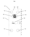
- the door comprises a door panel 1-2 (also referred to as door leaf or door wing) mountable within a door case 1-1.
- the front side view of Fig. 1 shows the door front side 8-1 of the door panel 1-2, while the door rear side (which is not visible in Fig. 1 ) is indicated at 8-1'.
- the door panel 1-2 comprises an integrated audio system comprising at least one audio source indicated at 1-3, which is mounted invisibly within the interior of the door panel 1-2 and is thus not visible from the outside, i.e. from the door front side 8-1 and the door rear side 8-1'.
- both the door front side 8-1 and the door rear side 8-1' are adapted for emitting sound of the at least one audio source 1-3, so that sound can be emitted on both sides of the door panel.
- a holding means 1-5 adapted for removably holding an electronic device 1-6 can be mounted on embodiments of the door panel 1-2, as shown in Fig. 1 .
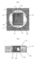
- a more detailed front side view of such a holding means 1-5 is shown in Fig. 2 .
- the holding means 1-5 comprises a rear wall 2-1 and a mounting frame 2-2.
- the mounting frame 2-2 allows inserting and removing the electronic device 1-6 and is preferably flexible, so that it can hold the electronic device 1-6 with a defined firmness to prevent that the device 1-6 drops out of the holding means 1-5 when the door is moved, e.g. opened, closed or slammed.
- mounting frames 2-2 as used in the present invention can take any form and dimensions so that they are capable of holding any types of electronic devices 1-6 capable of emitting audio signals, such as mobile phones, laptops, tablet PCs, personal digital assistants (PDAs), audio players (mp 3 players), etc.
- the mounting frame 2-2 may in some embodiments even be exchangeable to allow inserting different types of electronic devices 1-6 into the door panel 1-2, depending of the user preferences.
- Fig. 2 further shows an electric interface 2-3 that provides a power supply connectable to the electronic device 1-6.
- the electronic device 1-6 is immediately connected to the power supply upon insertion into the holding means 1-5 and can thus be recharged while docked.
- the depicted holding means 1-5 further comprises a cover plate 2-4 that covers the underlying mechanics of the holding means 1-5.
- the cover plate 2-4 may be provided in any material, colour and surface quality to provide a high-quality appearance of the holding means 1-5.
- Fig. 3 is a front side view of the holding means 1-5 of Fig. 2 with removed cover plate 2-4.
- the door panel 1-2 comprises in this example a milled contour 3-1 with three slide bearings 3-2. Due to the slide bearings 3-2, a rotation plate 3-3 of the holding means 1-5 is adapted for rotating preferably by 90°, so that an inserted electronic device 1-6 can be used in both portrait mode and landscape mode.
- any number of slide bearings 3-2 may be used, or more generally even any suitable mechanical means that allows the holding means (1-5 to rotate within the door panel 1-2 (in some embodiments allowing complete rotations around 360°).
- the electronic device 1-6 inserted into the holding means 1-5 may be used in any desired orientation.
- Fig. 3 further shows that the rotation plate 3-3 of the holding means 1-5 comprises two pivot bearings 3-4 which allow a turning element 3-5 mounted within the rotation plate 3-3 to be turned from one side of the door panel 1-2 to the other, preferably by 180°.
- any alternative means may be used for making the holding means 1-5 turnable within the door panel 1-2, in addition or alternatively to the above-described rotation feature.
- Fig. 4 shows a front side view of a control panel 1-4 of embodiments of the door panel 1-2 of the invention with opened lid 4-5.
- the control panel 1-4 comprises an amplifier 4-1 for amplifying audio signals received from the electronic device 1-6.
- the control panel 1-4 of Fig. 4 further comprises a radio module 4-2, which can be preferably inserted form-fittingly into a foamed body 4-3.
- the foamed body 4-3 further comprises one or more cable channels 4-4 in which all necessary cables may be inserted.
- the radio module 4-2 preferably receives audio signals over a wireless communication link, such as a WLAN, from the electronic device 1-6. The received audio signals are then used to steer the audio system 1-3 integrated into the door panel 1-2.
- the control panel 1-4 allows for controlling the integrated audio system of the inventive door panel 1-2.
- the control panel 1-4 preferably comprises a user interface comprising one or more interaction means, such as buttons, for allowing a user to set preferences of the door panel 1-2, such as the volume of the audio system, turn the entire sound functionality on and off and / or to selectively switch on and off the speaker functionality of each door side individually.
- control panel 1-4 may comprise a further holding means for receiving a further electronic device, such as a mobile phone, which can be connected and recharged, while the needed cables can be received into the cable channels 4-4 explained above.
- this additional electronic device may steer the integrated audio system 1-3 of the invention, preferably via a wireless communications link and the above-explained radio module 4-2.
- control panel may be realized independent of the further aspects described herein in various embodiments of the present door panel 1-2.
- Fig. 5 shows a perspective view of a carrier plate 5-1 of an exciter mounting module 7-1.
- the bottom side (also referred to as adhesion or gluing side) of the carrier plate 5-1 is preferably flat.
- the upper side of the carrier plate 5-1 of Fig. 5 comprises at least one exciter receiving area 5-2, a (mechanical) stopping means 5-3 and / or at least one spacing means 5-4 ( Fig. 5 shows six spacing means 5-4).
- an exciter 6-1 is inserted into the exciter receiving area 5-2 of the carrier plate 5-1.
- An exciter is one example of an audio source 6-1 and generally refers to a means for converting electrical impulses into acoustic waves, which can be mounted on top of a vibration-capable carrier element (the door panel 1-2 in the depicted embodiment) in order to stimulate a vibration of the carrier element, so that the latter emits sound.
- a vibration-capable carrier element the door panel 1-2 in the depicted embodiment
- an exciter 6-1 as disclosed in DE 10 2006 031 433 A1 may be used.
- the exciter 6-1 is glued onto the carrier plate 5-1.
- the exciter 6-1 When the exciter is connected to an audio amplifier via the connectors 6-2, the exciter 6-1 emits bending waves and stimulates vibrations of the material connected to the carrier plate 5-1. These vibrations result in audible sound. As a result, the carrier plate 5-1 (and thus the connected door panel 1-2) acts as a speaker membrane.
- Fig. 7 shows an exciter mounting module 7-1, comprising two carrier plates 5-1 (cf. Figs. 5 and 6 ) with respective exciters 6-1 mounted thereon.
- the carrier plates 5-1 are mounted in a mirrored manner and turned by 180° on top of each other and are preferably glued to form the exciter mounting module 7-1.
- the exciter mounting module 7-1 of Fig. 7 is eventually assembled (preferably glued) into a door panel 1-2. Both flat bottom surfaces of the respective carrier plates 5-1 are connected (preferably glued) to the respective door sides 8-1 and 8-1'.
- the two exciters 6-1 trigger by means of their emitted bending waves the respective carrier plates 5-1 and thus the respective door sides 8-1 and 8-1'. As a result, both sides of the door act as speaker membranes and emit sound.
- the described exciter mounting module 7-1 may be used for a variety of frequency ranges, for example exciter mounting modules 7-1 may provide treble tones, midrange tones and / or bass tones.
- the door panel 1-2 comprises at least one exciter mounting module 7-1 for treble and midrange tones and at least one exciter mounting module 7-1 for bass tones.
- Fig. 8 further shows the mechanical protection means provided by the mechanical stopping means 5-3.
- the stopping means 5-3 of the first carrier plate 5-1 (on the left hand side of Fig. 8 ) is positioned opposite to the exciter 6-1 of the second carrier plate 5-1 (on the right hand side of Fig. 8 ), wherein a defined space of air 8-2 is present between exciter 6-1 and stopping means 5-3.
- a movable part of the exciter 6-1 can only move to an extend defined by the air space 8-2.
- the stopping means 5-3 limits movements of the (movable parts) of the respective exciter 6-1 during a movement of the door panel 1-2.
- a greater movement amplitude results in the exciter 6-1 (i.e. its movable parts) hitting the stopping means 5-3, wherein the kinetic energy is absorbed by the stopping means 5-3.
- Exemplary methods for assembling the door panel 1-2 described above may comprise part of or all of the following steps:
- the advantageous exciter mounting module 7-1 admits this compression to a predefined degree, since the one or more spacing means 5-4 of the exciter mounting module 7-1 are adapted to compress to a predefined degree due to their advantageous shape.
- the spacing means 5-4 comprise elliptical-shaped elements to allow for a predefined and controlled compression. It will, however, be appreciated that alternative forms may be employed to allow a controlled compression of the one or more spacing means 5-4, such as circular forms, fan-like structures, or the like.
- the integrated audio system of the door panels 1-2 can be controlled by any type of electronic device 1-6, preferably via a wireless communication link such as a WLAN. Since one electronic device 1-6 is typically able to control multiple door panels 1-2 with respective integrated audio systems, a preferred example of a home audio system comprises at least two different examples of the inventive door panel 1-2:
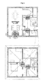
- a resulting home audio system is exemplarily shown in Fig. 9 .
- the kitchen door (which is typically most regularly frequented) is formed by an iDoor 1-2 to allow convenient access to the electronic device 1-6 that controls the home audio system.
- the kitchen-door iDoor 1-2 further transmits over a wireless channel the received audio signals to additional sDoors 1-2 mounted in other places of the facility. Further, the iDoor 1-2 also transmits the audio signals to a home audio appliance, such as the HiFi amplifier shown in Fig. 9 .
- this assembly allows for convenient audio experience in the entire facility without the need for bulky and un-aesthetic floor-standing speakers.
- the controlled HiFi amplifier in the living room provides for particular high-quality sound (e.g. when connected to a Dolby 5.1 system or the like).
- door panel 1-2 comprise one, part of, or all of the following features:
Landscapes
- Physics & Mathematics (AREA)
- Engineering & Computer Science (AREA)
- Acoustics & Sound (AREA)
- Signal Processing (AREA)
- Casings For Electric Apparatus (AREA)
Description
- The present invention concerns a door panel with integrated audio system.
- In recent years, invisible home audio systems have become increasingly popular. This is due to a decreased consumer acceptance of floor-standing speakers, which commonly take up a lot of space and only rarely meet the aesthetic requirements of modern homes. As a result to these changing consumer demands, speaker systems have been developed that can be integrated into walls, paintings and furniture elements.
- In this context, a variety of speaker systems are available which are able to stimulate vibration-capable elements such as paintings, cabinet doors, or the like, so that they act as speaker membranes. For example, the German utility model
DE 1968 161 U and the German patent applicationDE 10 2006 031 433 A1 disclose apparatuses for converting electrical impulses into acoustic waves, which can be mounted on top of vibration-capable carrier elements. - Further, the German utility model
DE 200 07 958 U1 discloses cabinet-type furniture, shelf walls, wall panellings, or other furniture elements, wherein a visible surface of such furniture elements is used as a flat surface speaker and voice coils, plungers, or the like are mounted on the rear surface. In other words, the visible side of the furniture is used as speaker, whereas the rear side serves for mounting the audio components. - A drawback of this arrangement, however, is that sound can only be emitted to one side of the furniture element. Further, the sensitive movable parts of the voice coils or similar audio components can be easily damaged when they are mounted on a movable carrier that is moved too fast. While this may rarely occur in stationary furniture, this is a particular drawback in moveable carrier elements such as room doors, which are frequently opened, closed, slammed, etc. In particular in the latter case, the mounted audio elements suffer extreme accelerating forces that may easily damage these sensitive components.
- A door which can emit sound towards both of its sides is known from
EP 1 085 780 A2WO 2008/027894 A2 , orUS 2008/164226 A1 . This document shows a household appliance like a refrigerator, wherein a holding means for an electronic device is mountable to the door of the appliance. - It is therefore the technical problem underlying the present invention to allow the usage of a room door as part of an audio system that at least partly overcomes the above explained disadvantages of the prior art.
- This problem is according to one aspect of the invention solved by a door panel as defined in
claim 1. - In the present invention, the door panel comprises a holding means for removably holding an electronic device capable of emitting audio signals. Accordingly, the door panel of the invention in this aspect features a holder in the sense of a docking station, which may feature dimensions for any of the above-explained types of electronic devices that may be used for controlling the integrated audio system. As a result, the inventive door panel is the ideal storage place for the above-mentioned electronic devices, or e.g. an iPad of Apple, Inc.
- Using wireless transmission techniques is particularly in this aspect, since transferring the audio content from the electronic device to the integrated audio system of the door panel is particularly easy due to the lack of any cables. Further, the played-back audio content may continue uninterruptedly when the electronic device is inserted and / or removed into / from the holding means during playback. In yet another aspect of the present invention, the wireless communication interface of the inventive door panel may comprise a repeater, adapted to amplify an existing wireless network, such as a home WLAN, thereby leading to an increased wireless coverage.
- The inventive holding means is in various aspects particularly intelligent, as will be explained in the following. For example, the holding means may be rotatable within the door panel to allow using the electronic device in at least a first and a second orientation. For example, the holding means may be rotatably connected to the door panel by at least one slide bearing. Accordingly, a user of the electronic device may freely rotate an electronic device inserted into the holding means and may thus use e.g. his/her iPad in portrait mode and / or landscape mode as desired. It will be appreciated that the electronic device preferably can be rotated to anywhere between 0° and 360° within the holding means to allow for particular flexibility.
- The holding means of the invention is turnable within the door panel to allow a front side of the electronic device to be turned to both sides of the door panel. For example, the holding means may be turnably connected to the door panel by at least one pivot bearing. Accordingly, in addition or alternatively to the above-described feature of rotating the electronic device essentially in parallel to the surface of the door panel, this aspect concerns the turning of the electronic device essentially perpendicular to the door panel surface. In other words, the electronic device may be turned "through" the door panel, so that a front side of the electronic device (typically featuring the user controls) may be viewed and controlled by a user from both sides of the door panel. As a result, the electronic device used for controlling the integrated audio system of the door panel is always accessible to the user, regardless of whether the door is opened or closed.
- In a further aspect of the present invention, the door panel may further comprise a power supply connectable to the electronic device upon insertion of the electronic device into the holding means. Accordingly, once attached to the holding means, the electronic device is preferably immediately supplied with electric power and thus recharged.
- In the following detailed description, presently preferred embodiments of the invention are further described with reference to the following figures:
- Fig. 1:
- A front view of a door panel with integrated audio system in accordance with an embodiment of the invention;
- Fig. 2:
- A front view of a holding means for a door panel in accordance with an embodiment of the invention;
- Fig. 3:
- A front view of a holding means for a door panel in accordance with an embodiment of the invention with removed cover plate;
- Fig. 4:
- A front view of a control panel with opened lid ;
- Fig. 5:
- A top view and a side view of a carrier plate of an exciter mounting module;
- Fig. 6:
- A side view of a carrier plate of an exciter mounting module with mounted exciter ;
- Fig. 7:
- A side view of two carrier plates forming an exciter mounting module;
- Fig. 8:
- A sectional view of an exciter mounting module assembled in a door panel; and
- Fig. 9:
- A schematic view of a home with a plurality of door panels .
- In the following, various exemplary door panels, as well as embodiments of door panels in accordance with the present invention are explained in more detail comprising features of an integrated audio system, a holding means for removably holding an electronic device, a control panel and / or at least one exciter mounting module.
- An example is described with respect to a room door as schematically shown in
Fig. 1 . As can be seen, the door comprises a door panel 1-2 (also referred to as door leaf or door wing) mountable within a door case 1-1. The front side view ofFig. 1 shows the door front side 8-1 of the door panel 1-2, while the door rear side (which is not visible inFig. 1 ) is indicated at 8-1'. The door panel 1-2 comprises an integrated audio system comprising at least one audio source indicated at 1-3, which is mounted invisibly within the interior of the door panel 1-2 and is thus not visible from the outside, i.e. from the door front side 8-1 and the door rear side 8-1'. - Advantageously, both the door front side 8-1 and the door rear side 8-1' are adapted for emitting sound of the at least one audio source 1-3, so that sound can be emitted on both sides of the door panel.
- A holding means 1-5 adapted for removably holding an electronic device 1-6 can be mounted on embodiments of the door panel 1-2, as shown in
Fig. 1 . A more detailed front side view of such a holding means 1-5 is shown inFig. 2 . As can be seen, the holding means 1-5 comprises a rear wall 2-1 and a mounting frame 2-2. The mounting frame 2-2 allows inserting and removing the electronic device 1-6 and is preferably flexible, so that it can hold the electronic device 1-6 with a defined firmness to prevent that the device 1-6 drops out of the holding means 1-5 when the door is moved, e.g. opened, closed or slammed. It will be appreciated that mounting frames 2-2 as used in the present invention can take any form and dimensions so that they are capable of holding any types of electronic devices 1-6 capable of emitting audio signals, such as mobile phones, laptops, tablet PCs, personal digital assistants (PDAs), audio players (mp3 players), etc. The mounting frame 2-2 may in some embodiments even be exchangeable to allow inserting different types of electronic devices 1-6 into the door panel 1-2, depending of the user preferences. -
Fig. 2 further shows an electric interface 2-3 that provides a power supply connectable to the electronic device 1-6. Preferably, the electronic device 1-6 is immediately connected to the power supply upon insertion into the holding means 1-5 and can thus be recharged while docked. The depicted holding means 1-5 further comprises a cover plate 2-4 that covers the underlying mechanics of the holding means 1-5. The cover plate 2-4 may be provided in any material, colour and surface quality to provide a high-quality appearance of the holding means 1-5. -
Fig. 3 is a front side view of the holding means 1-5 ofFig. 2 with removed cover plate 2-4. As can be seen, the door panel 1-2 comprises in this example a milled contour 3-1 with three slide bearings 3-2. Due to the slide bearings 3-2, a rotation plate 3-3 of the holding means 1-5 is adapted for rotating preferably by 90°, so that an inserted electronic device 1-6 can be used in both portrait mode and landscape mode. It will be appreciated that any number of slide bearings 3-2 may be used, or more generally even any suitable mechanical means that allows the holding means (1-5 to rotate within the door panel 1-2 (in some embodiments allowing complete rotations around 360°). As a result, the electronic device 1-6 inserted into the holding means 1-5 may be used in any desired orientation. -
Fig. 3 further shows that the rotation plate 3-3 of the holding means 1-5 comprises two pivot bearings 3-4 which allow a turning element 3-5 mounted within the rotation plate 3-3 to be turned from one side of the door panel 1-2 to the other, preferably by 180°. As will be apparent to those skilled in the art, any alternative means may be used for making the holding means 1-5 turnable within the door panel 1-2, in addition or alternatively to the above-described rotation feature. -
Fig. 4 shows a front side view of a control panel 1-4 of embodiments of the door panel 1-2 of the invention with opened lid 4-5. As can be seen, the control panel 1-4 comprises an amplifier 4-1 for amplifying audio signals received from the electronic device 1-6. The control panel 1-4 ofFig. 4 further comprises a radio module 4-2, which can be preferably inserted form-fittingly into a foamed body 4-3. The foamed body 4-3 further comprises one or more cable channels 4-4 in which all necessary cables may be inserted. The radio module 4-2 preferably receives audio signals over a wireless communication link, such as a WLAN, from the electronic device 1-6. The received audio signals are then used to steer the audio system 1-3 integrated into the door panel 1-2. - The control panel 1-4 allows for controlling the integrated audio system of the inventive door panel 1-2. To this end, the control panel 1-4 preferably comprises a user interface comprising one or more interaction means, such as buttons, for allowing a user to set preferences of the door panel 1-2, such as the volume of the audio system, turn the entire sound functionality on and off and / or to selectively switch on and off the speaker functionality of each door side individually.
- Further, the control panel 1-4 may comprise a further holding means for receiving a further electronic device, such as a mobile phone, which can be connected and recharged, while the needed cables can be received into the cable channels 4-4 explained above. In certain embodiments, also this additional electronic device may steer the integrated audio system 1-3 of the invention, preferably via a wireless communications link and the above-explained radio module 4-2.
- Those skilled in the art will appreciate that the above-explained control panel may be realized independent of the further aspects described herein in various embodiments of the present door panel 1-2.
-
Fig. 5 shows a perspective view of a carrier plate 5-1 of an exciter mounting module 7-1. The bottom side (also referred to as adhesion or gluing side) of the carrier plate 5-1 is preferably flat. The upper side of the carrier plate 5-1 ofFig. 5 comprises at least one exciter receiving area 5-2, a (mechanical) stopping means 5-3 and / or at least one spacing means 5-4 (Fig. 5 shows six spacing means 5-4). - In
Fig. 6 , an exciter 6-1 is inserted into the exciter receiving area 5-2 of the carrier plate 5-1. An exciter is one example of an audio source 6-1 and generally refers to a means for converting electrical impulses into acoustic waves, which can be mounted on top of a vibration-capable carrier element (the door panel 1-2 in the depicted embodiment) in order to stimulate a vibration of the carrier element, so that the latter emits sound. For example, an exciter 6-1 as disclosed inDE 10 2006 031 433 A1 may be used. In the embodiment ofFig. 6 , the exciter 6-1 is glued onto the carrier plate 5-1. When the exciter is connected to an audio amplifier via the connectors 6-2, the exciter 6-1 emits bending waves and stimulates vibrations of the material connected to the carrier plate 5-1. These vibrations result in audible sound. As a result, the carrier plate 5-1 (and thus the connected door panel 1-2) acts as a speaker membrane. -
Fig. 7 shows an exciter mounting module 7-1, comprising two carrier plates 5-1 (cf.Figs. 5 and 6 ) with respective exciters 6-1 mounted thereon. As can be seen, the carrier plates 5-1 are mounted in a mirrored manner and turned by 180° on top of each other and are preferably glued to form the exciter mounting module 7-1. - In
Fig. 8 , the exciter mounting module 7-1 ofFig. 7 is eventually assembled (preferably glued) into a door panel 1-2. Both flat bottom surfaces of the respective carrier plates 5-1 are connected (preferably glued) to the respective door sides 8-1 and 8-1'. The two exciters 6-1 trigger by means of their emitted bending waves the respective carrier plates 5-1 and thus the respective door sides 8-1 and 8-1'. As a result, both sides of the door act as speaker membranes and emit sound. - The described exciter mounting module 7-1 may be used for a variety of frequency ranges, for example exciter mounting modules 7-1 may provide treble tones, midrange tones and / or bass tones. In a preferred example, the door panel 1-2 comprises at least one exciter mounting module 7-1 for treble and midrange tones and at least one exciter mounting module 7-1 for bass tones.
-
Fig. 8 further shows the mechanical protection means provided by the mechanical stopping means 5-3. As can be seen, the stopping means 5-3 of the first carrier plate 5-1 (on the left hand side ofFig. 8 ) is positioned opposite to the exciter 6-1 of the second carrier plate 5-1 (on the right hand side ofFig. 8 ), wherein a defined space of air 8-2 is present between exciter 6-1 and stopping means 5-3. When the door is opened, closed, slammed, etc. and thus undergoes extensive acceleration forces, a movable part of the exciter 6-1 can only move to an extend defined by the air space 8-2. As a result, the stopping means 5-3 limits movements of the (movable parts) of the respective exciter 6-1 during a movement of the door panel 1-2. A greater movement amplitude results in the exciter 6-1 (i.e. its movable parts) hitting the stopping means 5-3, wherein the kinetic energy is absorbed by the stopping means 5-3. This way, the mechanical stability of the exciter 6-1 is ensured, the exciter 6-1 is protected against damages and established standards for doors are met. - Those skilled in the art will appreciate that the above-explained exciter mounting module may be realized independent of the further aspects described herein in various embodiments of the present door panel 1-2.
- Exemplary methods for assembling the door panel 1-2 described above may comprise part of or all of the following steps:
- connecting (preferably gluing) a first carrier plate 5-1 of at least one exciter mounting module 7-1 with a first door side wall 8-1 of the door panel 1-2 to be assembled;
- connecting (preferably gluing) a second carrier plate 5-1 of the at least one exciter mounting module 7-1 with a second door side wall 8-1' of the door panel 1-2 to be assembled; and
- compressing the first door side wall 8-1 and the second door side wall 8-1' to form the door panel 1-2.
- In the latter step, compressing of the door side walls results in the components inside the door panel to be compressed slightly. The advantageous exciter mounting module 7-1 admits this compression to a predefined degree, since the one or more spacing means 5-4 of the exciter mounting module 7-1 are adapted to compress to a predefined degree due to their advantageous shape. In the example shown in
Figs. 5 - 8 , the spacing means 5-4 comprise elliptical-shaped elements to allow for a predefined and controlled compression. It will, however, be appreciated that alternative forms may be employed to allow a controlled compression of the one or more spacing means 5-4, such as circular forms, fan-like structures, or the like. - As explained above, the integrated audio system of the door panels 1-2 can be controlled by any type of electronic device 1-6, preferably via a wireless communication link such as a WLAN. Since one electronic device 1-6 is typically able to control multiple door panels 1-2 with respective integrated audio systems, a preferred example of a home audio system comprises at least two different examples of the inventive door panel 1-2:
- a first door panel 1-2 with integrated holding means 1-5 (hereinafter referred to as "iDoor"), adapted for holding the electronic device 1-6; and
- at least one second door panel 1-2 without a holding means 1-5 (hereinafter referred to as "sDoor"). The "sDoor" example therefore, may implement any of the above-described capabilities of the inventive door panel 1-2, except for the holding means 1-5.
- A resulting home audio system is exemplarily shown in
Fig. 9 . As can be seen, the kitchen door (which is typically most regularly frequented) is formed by an iDoor 1-2 to allow convenient access to the electronic device 1-6 that controls the home audio system. The kitchen-door iDoor 1-2 further transmits over a wireless channel the received audio signals to additional sDoors 1-2 mounted in other places of the facility. Further, the iDoor 1-2 also transmits the audio signals to a home audio appliance, such as the HiFi amplifier shown inFig. 9 . - As a result, this assembly allows for convenient audio experience in the entire facility without the need for bulky and un-aesthetic floor-standing speakers. At the same time, the controlled HiFi amplifier in the living room provides for particular high-quality sound (e.g. when connected to a Dolby 5.1 system or the like).
- In summary, various examples of the door panel 1-2 comprise one, part of, or all of the following features:
- a holding means 1-5, adapted for removably receiving at least one electronic device 1-6, e.g. a tablet PC such as an iPad of Apple, Inc.;
- the electronic device 1-6 may be inserted into and removed from the holding means 1-5 entirely manually, i.e. without the need for special tools;
- electronic devices 1-6 are immediately connected to a power supply 2-3 upon insertion into the holding means 1-5 and are thus recharged;
- the holding means 1-5 can be rotated within the door panel 1-2, preferably by 90°;
- the holding means 1-5 can be turned within the door panel 1-2, preferably by 180° from one door side to the other;
- the control panel 1-4 comprises a controller 4-1 for setting preferences of the audio system 1-3, such as volume and / or switching on and off each door side individually (preferably by switching on and off individual exciters 6-1);
- the control panel 1-4 comprises a radio module 4-2, adapted for receiving audio signals e.g. over a wireless communication link;
- the control panel 1-4 is accessible through a lid 4-5;
- the integrated audio system 1-3 comprises at least one exciter mounting module 7-1, preferably at least one exciter mounting module 7-1 for treble and midrange tones and at least one exciter mounting module 7-1 for bass tones;
- the exciter mounting module 7-1 comprises two similar carrier plates 5-1, respectively adapted for receiving at least one exciter 6-i;
- a mechanical stopping means 5-3 of the carrier plate 5-1 limits movements of movable parts of a corresponding exciter 6-1 and thus protects the exciter 6-1 against damages.
Claims (3)
- A door panel (1-2), characterized in that the door panel (1-2) comprises:a. a holding means (1-5) for removably holding an electronic device (1-6) capable of emitting audio signals;b. wherein the holding means (1-5) is turnable within the door panel (1-2), so that a front side of the electronic device (1-6) may be viewed and controlled by a user from both sides of the door panel (1-2).
- The door panel (1-2) of claim 1, wherein the holding means (1-5) is turnably connected to the door panel (1-2) by at least one pivot bearing (3-4).
- The door panel of any of the preceding claims, further comprising a power supply connectable to the electronic device (1-6) upon insertion of the electronic device (1-6) into the holding means (1-5).
Priority Applications (1)
| Application Number | Priority Date | Filing Date | Title |
|---|---|---|---|
| EP20110150983 EP2477417B1 (en) | 2011-01-14 | 2011-01-14 | Door panel with holding means for an electronic device |
Applications Claiming Priority (1)
| Application Number | Priority Date | Filing Date | Title |
|---|---|---|---|
| EP20110150983 EP2477417B1 (en) | 2011-01-14 | 2011-01-14 | Door panel with holding means for an electronic device |
Publications (2)
| Publication Number | Publication Date |
|---|---|
| EP2477417A1 EP2477417A1 (en) | 2012-07-18 |
| EP2477417B1 true EP2477417B1 (en) | 2013-09-25 |
Family
ID=43858222
Family Applications (1)
| Application Number | Title | Priority Date | Filing Date |
|---|---|---|---|
| EP20110150983 Not-in-force EP2477417B1 (en) | 2011-01-14 | 2011-01-14 | Door panel with holding means for an electronic device |
Country Status (1)
| Country | Link |
|---|---|
| EP (1) | EP2477417B1 (en) |
Family Cites Families (13)
| Publication number | Priority date | Publication date | Assignee | Title |
|---|---|---|---|---|
| GB721120A (en) * | 1952-09-27 | 1954-12-29 | Oliver Clarence Eckel | Door body |
| DE1968161U (en) | 1966-04-08 | 1967-09-14 | Espro G M B H & Co K G | DEVICE FOR CONVERTING ELECTRICAL PULSES INTO SOUND WAVES. |
| US4550429A (en) * | 1983-06-03 | 1985-10-29 | Motorola, Inc. | Shock absorbing transducer module |
| ES2292166T3 (en) * | 1994-05-11 | 2008-03-01 | Ask Industries S.P.A. | QUICK MOUNT FOR SPEAKERS. |
| DE19944802C2 (en) * | 1999-09-20 | 2003-08-28 | Harman Audio Electronic Sys | door |
| DE20007958U1 (en) | 2000-05-03 | 2000-08-03 | Brinkmann, Udo, 49328 Melle | Furniture body |
| JP4413061B2 (en) * | 2004-04-09 | 2010-02-10 | 株式会社村上開明堂 | Display holding device |
| CH696885A5 (en) * | 2004-04-14 | 2008-01-15 | Art Over Tv Ag | Device of a movable wall paneling for concealing or highlighting a background. |
| WO2006132938A2 (en) * | 2005-06-03 | 2006-12-14 | Steel Case Development Corporation | Support arm assembly |
| DE102006031433B4 (en) | 2006-07-05 | 2011-06-22 | ELAC Electroacustic GmbH, 24113 | Exciter for area diaphragm loudspeakers |
| US10013381B2 (en) * | 2006-08-31 | 2018-07-03 | Bose Corporation | Media playing from a docked handheld media device |
| US7898812B2 (en) * | 2007-01-04 | 2011-03-01 | Whirlpool Corporation | Alternative hosts for multiple adapters and multiple consumer electronic devices |
| US7808779B2 (en) * | 2008-12-01 | 2010-10-05 | Lda, Llc | Rotatable dock for portable electronic devices |
-
2011
- 2011-01-14 EP EP20110150983 patent/EP2477417B1/en not_active Not-in-force
Also Published As
| Publication number | Publication date |
|---|---|
| EP2477417A1 (en) | 2012-07-18 |
Similar Documents
| Publication | Publication Date | Title |
|---|---|---|
| CA2517645C (en) | I-port controller | |
| JP2016516362A (en) | Decorative flat panel sound system | |
| US9961175B2 (en) | Smart device case with sound speaker | |
| US9226057B1 (en) | External sound systems with integral flat panel loudspeakers for portable electronic devices | |
| US20090161903A1 (en) | Docking station capable of being mounted to a sports support pole | |
| CN1976417B (en) | Television unit | |
| US7412206B1 (en) | Wireless audio system in a spa | |
| KR20170003653U (en) | Microphone-and-sound-box integrated apparatus | |
| EP2160887A1 (en) | Miniature wireless earring headset | |
| WO2008086145A2 (en) | Vertical consumer electronic device and adapter for mounting to a horizontal interface | |
| AU2003298537A1 (en) | Thin enclosure electroacoustical transducing | |
| CN104796642A (en) | A dual-mode Bluetooth sound-box television system and a dual-mode Bluetooth audio playing control method thereof | |
| WO2014186383A1 (en) | Portable loudspeakers and convertible personal audio headphone/loudspeakers | |
| WO2004034732A3 (en) | Acoustic reproduction device with improved directional characteristics | |
| US8103042B2 (en) | Case for containing a portable media player | |
| US20100086162A1 (en) | Method and a system to adjust the acoustical performance of a loudspeaker | |
| WO2007081671A3 (en) | Spherically housed loudspeaker system with force balancing | |
| CN205754721U (en) | Multifunctional Modular Speaker | |
| EP2477417A1 (en) | Door panel with integrated audio system | |
| US20070242846A1 (en) | Outdoor decorative audio output system | |
| CN206908763U (en) | A kind of pull bar sound equipment with detachable operating case | |
| CN2912173Y (en) | Loudspeakers of media player | |
| CN222691836U (en) | A portable folding video speaker | |
| CN112882543A (en) | Electronic equipment and adjusting method | |
| CN1774146B (en) | Portable wireless loud-speaker |
Legal Events
| Date | Code | Title | Description |
|---|---|---|---|
| PUAI | Public reference made under article 153(3) epc to a published international application that has entered the european phase |
Free format text: ORIGINAL CODE: 0009012 |
|
| AK | Designated contracting states |
Kind code of ref document: A1 Designated state(s): AL AT BE BG CH CY CZ DE DK EE ES FI FR GB GR HR HU IE IS IT LI LT LU LV MC MK MT NL NO PL PT RO RS SE SI SK SM TR |
|
| AX | Request for extension of the european patent |
Extension state: BA ME |
|
| RIN1 | Information on inventor provided before grant (corrected) |
Inventor name: KAESER, DIRK Inventor name: CHRIST, MARIE Inventor name: BUETH, WINFRIED Inventor name: PELSTER, MICHAEL Inventor name: KORTING, SEBASTIAN Inventor name: BUETH, JONAS Inventor name: BUETH, JOANA Inventor name: CHRIST, MAXIMILIAN Inventor name: FREREL, STEFAN Inventor name: MEYER, JOHANNA |
|
| 17P | Request for examination filed |
Effective date: 20130118 |
|
| RIC1 | Information provided on ipc code assigned before grant |
Ipc: H04R 1/02 20060101AFI20130211BHEP Ipc: H04R 27/00 20060101ALI20130211BHEP Ipc: H04R 7/04 20060101ALN20130211BHEP |
|
| GRAP | Despatch of communication of intention to grant a patent |
Free format text: ORIGINAL CODE: EPIDOSNIGR1 |
|
| INTG | Intention to grant announced |
Effective date: 20130405 |
|
| GRAS | Grant fee paid |
Free format text: ORIGINAL CODE: EPIDOSNIGR3 |
|
| GRAA | (expected) grant |
Free format text: ORIGINAL CODE: 0009210 |
|
| AK | Designated contracting states |
Kind code of ref document: B1 Designated state(s): AL AT BE BG CH CY CZ DE DK EE ES FI FR GB GR HR HU IE IS IT LI LT LU LV MC MK MT NL NO PL PT RO RS SE SI SK SM TR |
|
| REG | Reference to a national code |
Ref country code: GB Ref legal event code: FG4D |
|
| REG | Reference to a national code |
Ref country code: CH Ref legal event code: EP |
|
| REG | Reference to a national code |
Ref country code: AT Ref legal event code: REF Ref document number: 634107 Country of ref document: AT Kind code of ref document: T Effective date: 20131015 |
|
| REG | Reference to a national code |
Ref country code: IE Ref legal event code: FG4D |
|
| REG | Reference to a national code |
Ref country code: DE Ref legal event code: R096 Ref document number: 602011003165 Country of ref document: DE Effective date: 20131128 |
|
| REG | Reference to a national code |
Ref country code: CH Ref legal event code: NV Representative=s name: HEPP WENGER RYFFEL AG, CH |
|
| PG25 | Lapsed in a contracting state [announced via postgrant information from national office to epo] |
Ref country code: SE Free format text: LAPSE BECAUSE OF FAILURE TO SUBMIT A TRANSLATION OF THE DESCRIPTION OR TO PAY THE FEE WITHIN THE PRESCRIBED TIME-LIMIT Effective date: 20130925 Ref country code: NO Free format text: LAPSE BECAUSE OF FAILURE TO SUBMIT A TRANSLATION OF THE DESCRIPTION OR TO PAY THE FEE WITHIN THE PRESCRIBED TIME-LIMIT Effective date: 20131225 Ref country code: HR Free format text: LAPSE BECAUSE OF FAILURE TO SUBMIT A TRANSLATION OF THE DESCRIPTION OR TO PAY THE FEE WITHIN THE PRESCRIBED TIME-LIMIT Effective date: 20130925 Ref country code: LT Free format text: LAPSE BECAUSE OF FAILURE TO SUBMIT A TRANSLATION OF THE DESCRIPTION OR TO PAY THE FEE WITHIN THE PRESCRIBED TIME-LIMIT Effective date: 20130925 |
|
| REG | Reference to a national code |
Ref country code: AT Ref legal event code: MK05 Ref document number: 634107 Country of ref document: AT Kind code of ref document: T Effective date: 20130925 |
|
| REG | Reference to a national code |
Ref country code: NL Ref legal event code: VDEP Effective date: 20130925 |
|
| REG | Reference to a national code |
Ref country code: LT Ref legal event code: MG4D |
|
| PG25 | Lapsed in a contracting state [announced via postgrant information from national office to epo] |
Ref country code: SI Free format text: LAPSE BECAUSE OF FAILURE TO SUBMIT A TRANSLATION OF THE DESCRIPTION OR TO PAY THE FEE WITHIN THE PRESCRIBED TIME-LIMIT Effective date: 20130925 Ref country code: RS Free format text: LAPSE BECAUSE OF FAILURE TO SUBMIT A TRANSLATION OF THE DESCRIPTION OR TO PAY THE FEE WITHIN THE PRESCRIBED TIME-LIMIT Effective date: 20130925 Ref country code: FI Free format text: LAPSE BECAUSE OF FAILURE TO SUBMIT A TRANSLATION OF THE DESCRIPTION OR TO PAY THE FEE WITHIN THE PRESCRIBED TIME-LIMIT Effective date: 20130925 Ref country code: LV Free format text: LAPSE BECAUSE OF FAILURE TO SUBMIT A TRANSLATION OF THE DESCRIPTION OR TO PAY THE FEE WITHIN THE PRESCRIBED TIME-LIMIT Effective date: 20130925 Ref country code: GR Free format text: LAPSE BECAUSE OF FAILURE TO SUBMIT A TRANSLATION OF THE DESCRIPTION OR TO PAY THE FEE WITHIN THE PRESCRIBED TIME-LIMIT Effective date: 20131226 |
|
| PG25 | Lapsed in a contracting state [announced via postgrant information from national office to epo] |
Ref country code: BE Free format text: LAPSE BECAUSE OF FAILURE TO SUBMIT A TRANSLATION OF THE DESCRIPTION OR TO PAY THE FEE WITHIN THE PRESCRIBED TIME-LIMIT Effective date: 20130925 |
|
| PG25 | Lapsed in a contracting state [announced via postgrant information from national office to epo] |
Ref country code: EE Free format text: LAPSE BECAUSE OF FAILURE TO SUBMIT A TRANSLATION OF THE DESCRIPTION OR TO PAY THE FEE WITHIN THE PRESCRIBED TIME-LIMIT Effective date: 20130925 Ref country code: IS Free format text: LAPSE BECAUSE OF FAILURE TO SUBMIT A TRANSLATION OF THE DESCRIPTION OR TO PAY THE FEE WITHIN THE PRESCRIBED TIME-LIMIT Effective date: 20140125 Ref country code: SK Free format text: LAPSE BECAUSE OF FAILURE TO SUBMIT A TRANSLATION OF THE DESCRIPTION OR TO PAY THE FEE WITHIN THE PRESCRIBED TIME-LIMIT Effective date: 20130925 Ref country code: RO Free format text: LAPSE BECAUSE OF FAILURE TO SUBMIT A TRANSLATION OF THE DESCRIPTION OR TO PAY THE FEE WITHIN THE PRESCRIBED TIME-LIMIT Effective date: 20130925 Ref country code: NL Free format text: LAPSE BECAUSE OF FAILURE TO SUBMIT A TRANSLATION OF THE DESCRIPTION OR TO PAY THE FEE WITHIN THE PRESCRIBED TIME-LIMIT Effective date: 20130925 Ref country code: CZ Free format text: LAPSE BECAUSE OF FAILURE TO SUBMIT A TRANSLATION OF THE DESCRIPTION OR TO PAY THE FEE WITHIN THE PRESCRIBED TIME-LIMIT Effective date: 20130925 |
|
| PG25 | Lapsed in a contracting state [announced via postgrant information from national office to epo] |
Ref country code: AT Free format text: LAPSE BECAUSE OF FAILURE TO SUBMIT A TRANSLATION OF THE DESCRIPTION OR TO PAY THE FEE WITHIN THE PRESCRIBED TIME-LIMIT Effective date: 20130925 Ref country code: ES Free format text: LAPSE BECAUSE OF FAILURE TO SUBMIT A TRANSLATION OF THE DESCRIPTION OR TO PAY THE FEE WITHIN THE PRESCRIBED TIME-LIMIT Effective date: 20130925 Ref country code: PL Free format text: LAPSE BECAUSE OF FAILURE TO SUBMIT A TRANSLATION OF THE DESCRIPTION OR TO PAY THE FEE WITHIN THE PRESCRIBED TIME-LIMIT Effective date: 20130925 Ref country code: CY Free format text: LAPSE BECAUSE OF FAILURE TO SUBMIT A TRANSLATION OF THE DESCRIPTION OR TO PAY THE FEE WITHIN THE PRESCRIBED TIME-LIMIT Effective date: 20130925 |
|
| REG | Reference to a national code |
Ref country code: DE Ref legal event code: R097 Ref document number: 602011003165 Country of ref document: DE |
|
| PG25 | Lapsed in a contracting state [announced via postgrant information from national office to epo] |
Ref country code: PT Free format text: LAPSE BECAUSE OF FAILURE TO SUBMIT A TRANSLATION OF THE DESCRIPTION OR TO PAY THE FEE WITHIN THE PRESCRIBED TIME-LIMIT Effective date: 20140127 |
|
| PLBE | No opposition filed within time limit |
Free format text: ORIGINAL CODE: 0009261 |
|
| STAA | Information on the status of an ep patent application or granted ep patent |
Free format text: STATUS: NO OPPOSITION FILED WITHIN TIME LIMIT |
|
| PG25 | Lapsed in a contracting state [announced via postgrant information from national office to epo] |
Ref country code: LU Free format text: LAPSE BECAUSE OF FAILURE TO SUBMIT A TRANSLATION OF THE DESCRIPTION OR TO PAY THE FEE WITHIN THE PRESCRIBED TIME-LIMIT Effective date: 20140114 Ref country code: IT Free format text: LAPSE BECAUSE OF FAILURE TO SUBMIT A TRANSLATION OF THE DESCRIPTION OR TO PAY THE FEE WITHIN THE PRESCRIBED TIME-LIMIT Effective date: 20130925 |
|
| 26N | No opposition filed |
Effective date: 20140626 |
|
| PG25 | Lapsed in a contracting state [announced via postgrant information from national office to epo] |
Ref country code: DK Free format text: LAPSE BECAUSE OF FAILURE TO SUBMIT A TRANSLATION OF THE DESCRIPTION OR TO PAY THE FEE WITHIN THE PRESCRIBED TIME-LIMIT Effective date: 20130925 |
|
| REG | Reference to a national code |
Ref country code: DE Ref legal event code: R097 Ref document number: 602011003165 Country of ref document: DE Effective date: 20140626 |
|
| REG | Reference to a national code |
Ref country code: IE Ref legal event code: MM4A |
|
| PG25 | Lapsed in a contracting state [announced via postgrant information from national office to epo] |
Ref country code: IE Free format text: LAPSE BECAUSE OF NON-PAYMENT OF DUE FEES Effective date: 20140114 |
|
| PG25 | Lapsed in a contracting state [announced via postgrant information from national office to epo] |
Ref country code: MC Free format text: LAPSE BECAUSE OF FAILURE TO SUBMIT A TRANSLATION OF THE DESCRIPTION OR TO PAY THE FEE WITHIN THE PRESCRIBED TIME-LIMIT Effective date: 20130925 |
|
| GBPC | Gb: european patent ceased through non-payment of renewal fee |
Effective date: 20150114 |
|
| PG25 | Lapsed in a contracting state [announced via postgrant information from national office to epo] |
Ref country code: GB Free format text: LAPSE BECAUSE OF NON-PAYMENT OF DUE FEES Effective date: 20150114 |
|
| REG | Reference to a national code |
Ref country code: FR Ref legal event code: PLFP Year of fee payment: 6 |
|
| PG25 | Lapsed in a contracting state [announced via postgrant information from national office to epo] |
Ref country code: MT Free format text: LAPSE BECAUSE OF FAILURE TO SUBMIT A TRANSLATION OF THE DESCRIPTION OR TO PAY THE FEE WITHIN THE PRESCRIBED TIME-LIMIT Effective date: 20130925 |
|
| PG25 | Lapsed in a contracting state [announced via postgrant information from national office to epo] |
Ref country code: SM Free format text: LAPSE BECAUSE OF FAILURE TO SUBMIT A TRANSLATION OF THE DESCRIPTION OR TO PAY THE FEE WITHIN THE PRESCRIBED TIME-LIMIT Effective date: 20130925 |
|
| PG25 | Lapsed in a contracting state [announced via postgrant information from national office to epo] |
Ref country code: BG Free format text: LAPSE BECAUSE OF FAILURE TO SUBMIT A TRANSLATION OF THE DESCRIPTION OR TO PAY THE FEE WITHIN THE PRESCRIBED TIME-LIMIT Effective date: 20130925 |
|
| PG25 | Lapsed in a contracting state [announced via postgrant information from national office to epo] |
Ref country code: TR Free format text: LAPSE BECAUSE OF FAILURE TO SUBMIT A TRANSLATION OF THE DESCRIPTION OR TO PAY THE FEE WITHIN THE PRESCRIBED TIME-LIMIT Effective date: 20130925 Ref country code: HU Free format text: LAPSE BECAUSE OF FAILURE TO SUBMIT A TRANSLATION OF THE DESCRIPTION OR TO PAY THE FEE WITHIN THE PRESCRIBED TIME-LIMIT; INVALID AB INITIO Effective date: 20110114 |
|
| REG | Reference to a national code |
Ref country code: FR Ref legal event code: PLFP Year of fee payment: 7 |
|
| PGFP | Annual fee paid to national office [announced via postgrant information from national office to epo] |
Ref country code: FR Payment date: 20170124 Year of fee payment: 7 |
|
| PGFP | Annual fee paid to national office [announced via postgrant information from national office to epo] |
Ref country code: CH Payment date: 20180125 Year of fee payment: 8 |
|
| PG25 | Lapsed in a contracting state [announced via postgrant information from national office to epo] |
Ref country code: MK Free format text: LAPSE BECAUSE OF FAILURE TO SUBMIT A TRANSLATION OF THE DESCRIPTION OR TO PAY THE FEE WITHIN THE PRESCRIBED TIME-LIMIT Effective date: 20130925 |
|
| PG25 | Lapsed in a contracting state [announced via postgrant information from national office to epo] |
Ref country code: AL Free format text: LAPSE BECAUSE OF FAILURE TO SUBMIT A TRANSLATION OF THE DESCRIPTION OR TO PAY THE FEE WITHIN THE PRESCRIBED TIME-LIMIT Effective date: 20130925 Ref country code: FR Free format text: LAPSE BECAUSE OF NON-PAYMENT OF DUE FEES Effective date: 20180131 |
|
| REG | Reference to a national code |
Ref country code: FR Ref legal event code: ST Effective date: 20180928 |
|
| REG | Reference to a national code |
Ref country code: CH Ref legal event code: PL |
|
| PG25 | Lapsed in a contracting state [announced via postgrant information from national office to epo] |
Ref country code: LI Free format text: LAPSE BECAUSE OF NON-PAYMENT OF DUE FEES Effective date: 20190131 Ref country code: CH Free format text: LAPSE BECAUSE OF NON-PAYMENT OF DUE FEES Effective date: 20190131 |
|
| PGFP | Annual fee paid to national office [announced via postgrant information from national office to epo] |
Ref country code: DE Payment date: 20240125 Year of fee payment: 14 |
|
| REG | Reference to a national code |
Ref country code: DE Ref legal event code: R119 Ref document number: 602011003165 Country of ref document: DE |
|
| PG25 | Lapsed in a contracting state [announced via postgrant information from national office to epo] |
Ref country code: DE Free format text: LAPSE BECAUSE OF NON-PAYMENT OF DUE FEES Effective date: 20250801 |