EP2477294A1 - Overvoltage limiter in an aircraft electrical power generation system - Google Patents
Overvoltage limiter in an aircraft electrical power generation system Download PDFInfo
- Publication number
- EP2477294A1 EP2477294A1 EP11196211A EP11196211A EP2477294A1 EP 2477294 A1 EP2477294 A1 EP 2477294A1 EP 11196211 A EP11196211 A EP 11196211A EP 11196211 A EP11196211 A EP 11196211A EP 2477294 A1 EP2477294 A1 EP 2477294A1
- Authority
- EP
- European Patent Office
- Prior art keywords
- voltage
- generator
- overvoltage
- switch
- exciter
- Prior art date
- Legal status (The legal status is an assumption and is not a legal conclusion. Google has not performed a legal analysis and makes no representation as to the accuracy of the status listed.)
- Granted
Links
Images
Classifications
-
- H—ELECTRICITY
- H02—GENERATION; CONVERSION OR DISTRIBUTION OF ELECTRIC POWER
- H02H—EMERGENCY PROTECTIVE CIRCUIT ARRANGEMENTS
- H02H7/00—Emergency protective circuit arrangements specially adapted for specific types of electric machines or apparatus or for sectionalised protection of cable or line systems, and effecting automatic switching in the event of an undesired change from normal working conditions
- H02H7/06—Emergency protective circuit arrangements specially adapted for specific types of electric machines or apparatus or for sectionalised protection of cable or line systems, and effecting automatic switching in the event of an undesired change from normal working conditions for dynamo-electric generators; for synchronous capacitors
- H02H7/065—Emergency protective circuit arrangements specially adapted for specific types of electric machines or apparatus or for sectionalised protection of cable or line systems, and effecting automatic switching in the event of an undesired change from normal working conditions for dynamo-electric generators; for synchronous capacitors against excitation faults
-
- H—ELECTRICITY
- H02—GENERATION; CONVERSION OR DISTRIBUTION OF ELECTRIC POWER
- H02M—APPARATUS FOR CONVERSION BETWEEN AC AND AC, BETWEEN AC AND DC, OR BETWEEN DC AND DC, AND FOR USE WITH MAINS OR SIMILAR POWER SUPPLY SYSTEMS; CONVERSION OF DC OR AC INPUT POWER INTO SURGE OUTPUT POWER; CONTROL OR REGULATION THEREOF
- H02M1/00—Details of apparatus for conversion
- H02M1/32—Means for protecting converters other than automatic disconnection
-
- H—ELECTRICITY
- H02—GENERATION; CONVERSION OR DISTRIBUTION OF ELECTRIC POWER
- H02M—APPARATUS FOR CONVERSION BETWEEN AC AND AC, BETWEEN AC AND DC, OR BETWEEN DC AND DC, AND FOR USE WITH MAINS OR SIMILAR POWER SUPPLY SYSTEMS; CONVERSION OF DC OR AC INPUT POWER INTO SURGE OUTPUT POWER; CONTROL OR REGULATION THEREOF
- H02M1/00—Details of apparatus for conversion
- H02M1/08—Circuits specially adapted for the generation of control voltages for semiconductor devices incorporated in static converters
-
- H—ELECTRICITY
- H02—GENERATION; CONVERSION OR DISTRIBUTION OF ELECTRIC POWER
- H02M—APPARATUS FOR CONVERSION BETWEEN AC AND AC, BETWEEN AC AND DC, OR BETWEEN DC AND DC, AND FOR USE WITH MAINS OR SIMILAR POWER SUPPLY SYSTEMS; CONVERSION OF DC OR AC INPUT POWER INTO SURGE OUTPUT POWER; CONTROL OR REGULATION THEREOF
- H02M5/00—Conversion of AC power input into AC power output, e.g. for change of voltage, for change of frequency, for change of number of phases
- H02M5/02—Conversion of AC power input into AC power output, e.g. for change of voltage, for change of frequency, for change of number of phases without intermediate conversion into DC
- H02M5/04—Conversion of AC power input into AC power output, e.g. for change of voltage, for change of frequency, for change of number of phases without intermediate conversion into DC by static converters
- H02M5/22—Conversion of AC power input into AC power output, e.g. for change of voltage, for change of frequency, for change of number of phases without intermediate conversion into DC by static converters using discharge tubes with control electrode or semiconductor devices with control electrode
- H02M5/275—Conversion of AC power input into AC power output, e.g. for change of voltage, for change of frequency, for change of number of phases without intermediate conversion into DC by static converters using discharge tubes with control electrode or semiconductor devices with control electrode using devices of a triode or transistor type requiring continuous application of a control signal
- H02M5/293—Conversion of AC power input into AC power output, e.g. for change of voltage, for change of frequency, for change of number of phases without intermediate conversion into DC by static converters using discharge tubes with control electrode or semiconductor devices with control electrode using devices of a triode or transistor type requiring continuous application of a control signal using semiconductor devices only
-
- H—ELECTRICITY
- H02—GENERATION; CONVERSION OR DISTRIBUTION OF ELECTRIC POWER
- H02P—CONTROL OR REGULATION OF ELECTRIC MOTORS, ELECTRIC GENERATORS OR DYNAMO-ELECTRIC CONVERTERS; CONTROLLING TRANSFORMERS, REACTORS OR CHOKE COILS
- H02P9/00—Arrangements for controlling electric generators for the purpose of obtaining a desired output
- H02P9/006—Means for protecting the generator by using control
-
- H—ELECTRICITY
- H02—GENERATION; CONVERSION OR DISTRIBUTION OF ELECTRIC POWER
- H02P—CONTROL OR REGULATION OF ELECTRIC MOTORS, ELECTRIC GENERATORS OR DYNAMO-ELECTRIC CONVERTERS; CONTROLLING TRANSFORMERS, REACTORS OR CHOKE COILS
- H02P9/00—Arrangements for controlling electric generators for the purpose of obtaining a desired output
- H02P9/14—Arrangements for controlling electric generators for the purpose of obtaining a desired output by variation of field
- H02P9/26—Arrangements for controlling electric generators for the purpose of obtaining a desired output by variation of field using discharge tubes or semiconductor devices
- H02P9/30—Arrangements for controlling electric generators for the purpose of obtaining a desired output by variation of field using discharge tubes or semiconductor devices using semiconductor devices
- H02P9/302—Brushless excitation
-
- H—ELECTRICITY
- H02—GENERATION; CONVERSION OR DISTRIBUTION OF ELECTRIC POWER
- H02M—APPARATUS FOR CONVERSION BETWEEN AC AND AC, BETWEEN AC AND DC, OR BETWEEN DC AND DC, AND FOR USE WITH MAINS OR SIMILAR POWER SUPPLY SYSTEMS; CONVERSION OF DC OR AC INPUT POWER INTO SURGE OUTPUT POWER; CONTROL OR REGULATION THEREOF
- H02M5/00—Conversion of AC power input into AC power output, e.g. for change of voltage, for change of frequency, for change of number of phases
- H02M5/02—Conversion of AC power input into AC power output, e.g. for change of voltage, for change of frequency, for change of number of phases without intermediate conversion into DC
- H02M5/04—Conversion of AC power input into AC power output, e.g. for change of voltage, for change of frequency, for change of number of phases without intermediate conversion into DC by static converters
- H02M5/22—Conversion of AC power input into AC power output, e.g. for change of voltage, for change of frequency, for change of number of phases without intermediate conversion into DC by static converters using discharge tubes with control electrode or semiconductor devices with control electrode
- H02M5/275—Conversion of AC power input into AC power output, e.g. for change of voltage, for change of frequency, for change of number of phases without intermediate conversion into DC by static converters using discharge tubes with control electrode or semiconductor devices with control electrode using devices of a triode or transistor type requiring continuous application of a control signal
- H02M5/293—Conversion of AC power input into AC power output, e.g. for change of voltage, for change of frequency, for change of number of phases without intermediate conversion into DC by static converters using discharge tubes with control electrode or semiconductor devices with control electrode using devices of a triode or transistor type requiring continuous application of a control signal using semiconductor devices only
- H02M5/2932—Conversion of AC power input into AC power output, e.g. for change of voltage, for change of frequency, for change of number of phases without intermediate conversion into DC by static converters using discharge tubes with control electrode or semiconductor devices with control electrode using devices of a triode or transistor type requiring continuous application of a control signal using semiconductor devices only with automatic control of output voltage, current or power
Definitions
- This disclosure relates to a generator for a power generating system.
- the disclosure relates to an overvoltage limiting configuration and a method of limiting the output voltage of a generator to a desired voltage under overvoltage conditions.
- variable frequency generator includes a permanent magnet generator (PMG), an exciter, and a main generator mounted for rotation on a common shaft.
- the shaft is driven by a prime mover.
- a generator control unit converts alternating current from the PMG to provide DC current to the exciter. Current from the exciter is fed to the main generator, which produces a voltage output.
- an overvoltage condition may result, which produces a higher than desired output voltage from the main generator.
- desired overvoltage protection remains lacking. For example, one typical overvoltage management strategy simply trips a switch to an open condition once a overvoltage threshold has been reached. Another strategy delays tripping the switch depending upon the duration of the overvoltage to avoid needlessly tripping the switch for a brief overvoltage spike. In both of the above strategies, once the undesired overvoltage has occurred, the generator is de-energized and effectively disabled, which may require the switch to be mechanically reset. Thus, the generator is not capable of supplying power during a persistent overvoltage condition.
- a method of limiting a generator voltage with a voltage limiter in an overvoltage condition is provided.
- the voltage limiter enables the generator to supply power during a persistent overvoltage condition without tripping the conventional overvoltage protection switch.
- the voltage limiter is unable to maintain the output voltage below a maximum overvoltage or if the overvoltage condition exists longer than allowable duration, then the conventional overvoltage switch is tripped.
- the voltage limiter provides an additional, intermediate safeguard to the conventional overvoltage switch.
- One method includes limiting the actual POR voltage to a specified fixed threshold.
- a switch is modulated to maintain the output voltage to the specified voltage, enabling the generator to continue to supply power throughout an overvoltage condition.
- Another method includes limiting the actual POR voltage to a varying threshold profile.
- the varying threshold profile becomes active when the POR voltage exceeds a specified minimum over voltage threshold.
- the varying threshold profile starts at an upper overvoltage threshold level and continues to decrease as a function of time.
- a switch is modulated according to voltage error between the actual POR voltage and the reference threshold voltage. Excitation current flow within the generator is interrupted based upon the voltage error to limit the actual POR voltage to no more than the specified voltage iteratively, thus, enabling the generator to continue to supply power throughout an overvoltage condition.
- a generator includes a permanent magnet generator, an exciter and a main generator mounted for rotation on a shaft.
- the main generator is configured to produce a voltage output.
- a generator control unit includes a circuit configured to provide required direct current to the exciter from the permanent magnet generator source.
- a limiting switch is also provided in the circuit and is configured to change between open and closed conditions. The switch is configured to flow current in the circuit in the closed condition and interrupt current flow in the open condition thereby regulating the power going to the exciter drive circuitry.
- An overvoltage limit controller is programmed to determine an amount of overvoltage of the output voltage (actual POR voltage) exceeding a reference threshold voltage.
- a reference threshold voltage is either a specified fixed voltage or a varying voltage as a function of time.
- the varying voltage profile is activated when the output voltage exceeds a specified minimum voltage (lowest threshold voltage level that sets the over voltage condition).
- the switch is modulated between the open and closed conditions based upon the error between the actual POR voltage and reference threshold voltage thereby limiting the actual POR voltage to the reference threshold voltage.
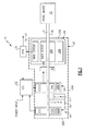
- FIG. 1 schematically illustrates selected portions of an example generator 10 driven by a prime mover 12 such as a gas turbine engine and for generating electrical current when being driven by the prime mover 12.
- the generator 10 may generally include a dynamoelectric portion 14, hydraulic pump 16 and a gear train 18, all contained within a common housing assembly 20.
- the dynamoelectric portion 14 in the disclosed exemplary embodiment is a 3-phase machine that includes three machines 22, 24 and 26 mounted on a rotor shaft 28 along an axis of rotation A.
- Stator assemblies 22B, 24B, 26B of the three machines are installed in the housing assembly 20, and the three rotor assemblies 22A, 24A, 26A are installed on the rotor shaft 28.
- the housing assembly 20 may be closed with a drive end cover assembly or housing portion 20A, through which the rotor shaft 28 extends, and an end plate 20B.
- the first machine 22 includes a permanent magnet generator (PMG) with a rotor assembly 22A and a stator assembly 22B.
- the stator assembly 22B supplies power for generator excitation, as well as power for other components of the electrical system.
- the second machine 24 includes an exciter with a rotor assembly 24A and a stator assembly 24B.
- the exciter receives field excitation from the PMG through a GCU 32 (Generator Control Unit).
- the output of the rotor assembly 24A is supplied to a shaft mounted diode pack 30.
- the diode pack 30 may be divided into six diode groups to provide a 3-phase full wave bridge rectification.
- the DC output of the diode pack 30 supplies the third machine 26, or main generator, which provides a desired output voltage from a POR 34 (Point of Regulation).
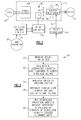
- the GCU 32 includes a bridge rectifier 36 that converts 3-phase alternating current from the PMG 22 to DC power.
- the bridge rectifier 36 is arranged in a circuit 38 with an exciter field driver 44, which provides power to the exciter 24.
- the exciter field driver 44 includes an H-bridge having a pair of MOSFETs and a pair of fly-back diodes.
- a capacitor 42 is provided in the circuit 38 to reduce the DC voltage ripple from the bridge rectifier 36.
- An exciter controller 45 is electrically connected between the POR 34 and the exciter field driver 44.
- the exciter controller 45 receives point of regulation (POR) voltage from the POR 34 and provides a desired voltage/current command signal 47 in response thereto to the exciter field driver 44 to achieve the desired output voltage from the main generator 26.
- POR point of regulation
- a faulty desired voltage/current command signal may result in improper control of the exciter field driver 44 thereby resulting in an overvoltage condition.
- the exciter field driver may also include a conventional overvoltage protection switch that trips if a maximum overvoltage is exceeded or the duration of overvoltage condition exceeds allowable limits.
- a switch 46 such as a MOSFET, is provided in the circuit in a return path 40 from the exciter field driver 44 to the bridge rectifier 36.
- the switch 46 includes open and closed conditions. Current flows through the circuit 38 in the closed condition, and current flow is interrupted in the open condition.
- An overvoltage limit controller 48 is electrically connected to the switch 46 and receives signals from the POR 34.
- the overvoltage limit controller 48 determines an amount of overvoltage exceeding a specified voltage in an overvoltage condition by detecting all three phase voltages.
- the specified voltage for over voltage condition for the main generator 26 may be 240 volts.
- the point of regulation (POR) voltage from the main generator 26 may be 300 volts for example, corresponding to an overvoltage condition.
- the overvoltage threshold for the limiter may be set at a fixed value of 280 V.
- the overvoltage limit controller 48 then modulates the switch 46 to limit the POR voltage 34 to 280 V as long as the overvoltage condition exists.
- the generator 10 can continue to supply power to a component, such as an aircraft system.
- a method of limiting overvoltage of the generator is generally indicated at 50.
- the actual POR voltage is measured, as indicated at block 51.
- the amount of overvoltage is compared to a specified voltage (for example, 280V), which can be the lowest threshold voltage considered as overvoltage, as indicated at block 52.
- the switch is modulated to maintain the output voltage at the specified voltage throughout the overvoltage condition, as indicated at block 54. As a result, the current flow between the PMG and exciter is interrupted to limit the voltage (block 56).
- the conventional voltage protection switch may be tripped, as indicated at block 58.
- the overvoltage limit controller 48 uses a reference voltage threshold based upon the duration of the overvoltage condition, and modulates the switch 46 to limit the POR voltage to the reference voltage threshold; the longer the duration, the lower the reference voltage threshold will be.
- This varying threshold profile starts at an upper overvoltage threshold, which is less than the maximum overvoltage, and continues to decrease as a function of time. This process occurs iteratively such that the actual POR voltage converges on the desired voltage below the specified voltage.
- a rate of change of voltage may also be used in combination with the POR voltage to allow limiting the voltage sooner in the case of rapidly changing POR voltages.
- the overvoltage limit controller commands the switch open and closed to interrupt current flow within the circuit 38 based upon the error between the actual POR voltage, or a combination of actual POR voltage and weighted rate of change in voltage, and the reference threshold voltage to limit the output voltage (actual POR voltage) to the desired voltage.
- the rate of open and close of the switch is determined by the degree of hysteresis provided at the reference voltage threshold. That is, operation of the switch 46 based upon the reference voltage threshold will achieve the desired voltage at the main generator. For example, an output voltage of 300V may necessitate the switch to be modulated OFF and ON for 40 ms into the overvoltage condition to limit the output voltage to 300V and then continue to limit the output voltage to lower voltages as time progresses.
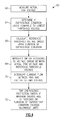
- This method of limiting overvoltage of the generators is generally indicated at 60 in Figure 4 .
- the actual POR voltage is measured, as indicated at block 62.
- the amount of overvoltage is compared to a specified voltage, which is the lowest threshold voltage considered as overvoltage, as indicated at block 64.
- a reference threshold voltage is calculated based upon the duration of overvoltage (block 66).
- the switch is modulated according to a voltage error between the actual POR voltage and reference threshold voltage, as indicated at block 68. As a result, the current flow between the PMG and exciter is interrupted to limit the voltage (block 70).
- the steps of blocks 66, 68, 70 may be repeated to iteratively converge upon the desired voltage and achieve an output voltage at or below the specified voltage.
- the conventional voltage protection switch may be tripped, as indicated at block 72.
- the switch 46 can be used and tripped when implementing the conventional voltage protection feature. That is, the same switch can be used for both overvoltage limiting and overvoltage protection.
Landscapes
- Engineering & Computer Science (AREA)
- Power Engineering (AREA)
- Control Of Eletrric Generators (AREA)
Abstract
Description
- This disclosure relates to a generator for a power generating system. In particular, the disclosure relates to an overvoltage limiting configuration and a method of limiting the output voltage of a generator to a desired voltage under overvoltage conditions.
- One type of aircraft electrical power generating system includes a variable frequency generator. The variable frequency generator includes a permanent magnet generator (PMG), an exciter, and a main generator mounted for rotation on a common shaft. The shaft is driven by a prime mover.
- A generator control unit (GCU) converts alternating current from the PMG to provide DC current to the exciter. Current from the exciter is fed to the main generator, which produces a voltage output.
- Under some fault conditions, an overvoltage condition may result, which produces a higher than desired output voltage from the main generator. There are many strategies for limiting or preventing overvoltage conditions, but desired overvoltage protection remains lacking. For example, one typical overvoltage management strategy simply trips a switch to an open condition once a overvoltage threshold has been reached. Another strategy delays tripping the switch depending upon the duration of the overvoltage to avoid needlessly tripping the switch for a brief overvoltage spike. In both of the above strategies, once the undesired overvoltage has occurred, the generator is de-energized and effectively disabled, which may require the switch to be mechanically reset. Thus, the generator is not capable of supplying power during a persistent overvoltage condition.
- A method of limiting a generator voltage with a voltage limiter in an overvoltage condition is provided. The voltage limiter enables the generator to supply power during a persistent overvoltage condition without tripping the conventional overvoltage protection switch. However, if the voltage limiter is unable to maintain the output voltage below a maximum overvoltage or if the overvoltage condition exists longer than allowable duration, then the conventional overvoltage switch is tripped. Thus, the voltage limiter provides an additional, intermediate safeguard to the conventional overvoltage switch.
- One method includes limiting the actual POR voltage to a specified fixed threshold. A switch is modulated to maintain the output voltage to the specified voltage, enabling the generator to continue to supply power throughout an overvoltage condition.
- Another method includes limiting the actual POR voltage to a varying threshold profile. The varying threshold profile becomes active when the POR voltage exceeds a specified minimum over voltage threshold. The varying threshold profile starts at an upper overvoltage threshold level and continues to decrease as a function of time. A switch is modulated according to voltage error between the actual POR voltage and the reference threshold voltage. Excitation current flow within the generator is interrupted based upon the voltage error to limit the actual POR voltage to no more than the specified voltage iteratively, thus, enabling the generator to continue to supply power throughout an overvoltage condition.
- A generator includes a permanent magnet generator, an exciter and a main generator mounted for rotation on a shaft. The main generator is configured to produce a voltage output. A generator control unit includes a circuit configured to provide required direct current to the exciter from the permanent magnet generator source. In addition to the exciter field drive circuitry that normally regulates the POR voltage output from the main generator by controlling the exciter field current, a limiting switch is also provided in the circuit and is configured to change between open and closed conditions. The switch is configured to flow current in the circuit in the closed condition and interrupt current flow in the open condition thereby regulating the power going to the exciter drive circuitry.
- An overvoltage limit controller is programmed to determine an amount of overvoltage of the output voltage (actual POR voltage) exceeding a reference threshold voltage. A reference threshold voltage is either a specified fixed voltage or a varying voltage as a function of time. The varying voltage profile is activated when the output voltage exceeds a specified minimum voltage (lowest threshold voltage level that sets the over voltage condition). The switch is modulated between the open and closed conditions based upon the error between the actual POR voltage and reference threshold voltage thereby limiting the actual POR voltage to the reference threshold voltage.
- The disclosure can be further understood by reference to the following detailed description when considered in connection with the accompanying drawings wherein:
-
Figure 1 is a general schematic sectional view of a generator for a gas turbine engine. -
Figure 2 is a schematic view of an overvoltage protection arrangement for a generator. -
Figure 3 is a flow chart illustrating a method of limiting a generator voltage in an overvoltage condition. -
Figure 4 is a flow chart illustrating another method of limiting a generator in an overvoltage condition. -
Figure 1 schematically illustrates selected portions of anexample generator 10 driven by aprime mover 12 such as a gas turbine engine and for generating electrical current when being driven by theprime mover 12. Thegenerator 10 may generally include adynamoelectric portion 14,hydraulic pump 16 and agear train 18, all contained within a common housing assembly 20. - The
dynamoelectric portion 14 in the disclosed exemplary embodiment is a 3-phase machine that includes threemachines A. Stator assemblies rotor assemblies housing portion 20A, through which the rotor shaft 28 extends, and anend plate 20B. - The
first machine 22 includes a permanent magnet generator (PMG) with arotor assembly 22A and astator assembly 22B. Thestator assembly 22B supplies power for generator excitation, as well as power for other components of the electrical system. Thesecond machine 24 includes an exciter with arotor assembly 24A and astator assembly 24B. The exciter receives field excitation from the PMG through a GCU 32 (Generator Control Unit). The output of therotor assembly 24A is supplied to a shaft mounteddiode pack 30. Thediode pack 30 may be divided into six diode groups to provide a 3-phase full wave bridge rectification. The DC output of thediode pack 30 supplies thethird machine 26, or main generator, which provides a desired output voltage from a POR 34 (Point of Regulation). - Portions of the
GCU 32 are illustrated in more detail inFigure 2 . TheGCU 32 includes a bridge rectifier 36 that converts 3-phase alternating current from thePMG 22 to DC power. The bridge rectifier 36 is arranged in acircuit 38 with anexciter field driver 44, which provides power to theexciter 24. In one example, theexciter field driver 44 includes an H-bridge having a pair of MOSFETs and a pair of fly-back diodes. - A
capacitor 42 is provided in thecircuit 38 to reduce the DC voltage ripple from the bridge rectifier 36. Anexciter controller 45 is electrically connected between thePOR 34 and theexciter field driver 44. Theexciter controller 45 receives point of regulation (POR) voltage from thePOR 34 and provides a desired voltage/current command signal 47 in response thereto to theexciter field driver 44 to achieve the desired output voltage from themain generator 26. A faulty desired voltage/current command signal may result in improper control of theexciter field driver 44 thereby resulting in an overvoltage condition. The exciter field driver may also include a conventional overvoltage protection switch that trips if a maximum overvoltage is exceeded or the duration of overvoltage condition exceeds allowable limits. - A
switch 46, such as a MOSFET, is provided in the circuit in areturn path 40 from theexciter field driver 44 to the bridge rectifier 36. Theswitch 46 includes open and closed conditions. Current flows through thecircuit 38 in the closed condition, and current flow is interrupted in the open condition. An overvoltage limit controller 48 is electrically connected to theswitch 46 and receives signals from thePOR 34. The overvoltage limit controller 48 determines an amount of overvoltage exceeding a specified voltage in an overvoltage condition by detecting all three phase voltages. In one example, the specified voltage for over voltage condition for themain generator 26 may be 240 volts. The point of regulation (POR) voltage from themain generator 26 may be 300 volts for example, corresponding to an overvoltage condition. In one implementation of the voltage limiter, the overvoltage threshold for the limiter may be set at a fixed value of 280 V. The overvoltage limit controller 48 then modulates theswitch 46 to limit thePOR voltage 34 to 280 V as long as the overvoltage condition exists. Thus, thegenerator 10 can continue to supply power to a component, such as an aircraft system. - Referring to
Figure 3 , a method of limiting overvoltage of the generator is generally indicated at 50. The actual POR voltage is measured, as indicated atblock 51. The amount of overvoltage is compared to a specified voltage (for example, 280V), which can be the lowest threshold voltage considered as overvoltage, as indicated atblock 52. The switch is modulated to maintain the output voltage at the specified voltage throughout the overvoltage condition, as indicated atblock 54. As a result, the current flow between the PMG and exciter is interrupted to limit the voltage (block 56). If the overvoltage limit controller is unable to maintain the output voltage at or below the specified voltage and/or the output voltage exceeds a maximum overvoltage or the duration of overvoltage condition exceeds allowable limits, then the conventional voltage protection switch may be tripped, as indicated atblock 58. - In another implementation, the overvoltage limit controller 48 uses a reference voltage threshold based upon the duration of the overvoltage condition, and modulates the
switch 46 to limit the POR voltage to the reference voltage threshold; the longer the duration, the lower the reference voltage threshold will be. This varying threshold profile starts at an upper overvoltage threshold, which is less than the maximum overvoltage, and continues to decrease as a function of time. This process occurs iteratively such that the actual POR voltage converges on the desired voltage below the specified voltage. - A rate of change of voltage may also be used in combination with the POR voltage to allow limiting the voltage sooner in the case of rapidly changing POR voltages.
- The overvoltage limit controller commands the switch open and closed to interrupt current flow within the
circuit 38 based upon the error between the actual POR voltage, or a combination of actual POR voltage and weighted rate of change in voltage, and the reference threshold voltage to limit the output voltage (actual POR voltage) to the desired voltage. The rate of open and close of the switch is determined by the degree of hysteresis provided at the reference voltage threshold. That is, operation of theswitch 46 based upon the reference voltage threshold will achieve the desired voltage at the main generator. For example, an output voltage of 300V may necessitate the switch to be modulated OFF and ON for 40 ms into the overvoltage condition to limit the output voltage to 300V and then continue to limit the output voltage to lower voltages as time progresses. - This method of limiting overvoltage of the generators is generally indicated at 60 in
Figure 4 . The actual POR voltage is measured, as indicated atblock 62. The amount of overvoltage is compared to a specified voltage, which is the lowest threshold voltage considered as overvoltage, as indicated atblock 64. A reference threshold voltage is calculated based upon the duration of overvoltage (block 66). The switch is modulated according to a voltage error between the actual POR voltage and reference threshold voltage, as indicated atblock 68. As a result, the current flow between the PMG and exciter is interrupted to limit the voltage (block 70). The steps ofblocks block 72. - The
switch 46 can be used and tripped when implementing the conventional voltage protection feature. That is, the same switch can be used for both overvoltage limiting and overvoltage protection. - Although an example embodiment has been disclosed, a worker of ordinary skill in this art would recognize that certain modifications would come within the scope of the claims. For that reason, the following claims should be studied to determine their true scope and content.
Claims (15)
- A method of limiting a generator voltage in an overvoltage condition comprising the steps of:a) determining an amount of overvoltage of a generator output voltage exceeding a specified voltage;b) calculating a reference threshold voltage based upon the duration of overvoltage;c) modulating a switch (46) according to a voltage error between the output voltage and the reference threshold voltage; andd) interrupting current flow within the generator (14) based upon the voltage error to limit the output voltage to a desired voltage.
- A method of limiting a generator voltage in an overvoltage condition comprising the steps of:a) determining an amount of overvoltage of a generator output voltage exceeding a specified voltage;b) modulating a switch to the specified voltage; andc) interrupting current flow within the generator based upon the voltage error to limit the output voltage to a desired voltage.
- The method according to claim 1, wherein step a) includes using point of regulation voltage.
- The method according to claim 1 or 3, wherein step b) includes decreasing the reference threshold voltage as the duration of the overvoltage increases.
- The method according to any preceding claim, wherein the switch (46) is arranged between a permanent magnet generator (22) and an exciter (24), and step d) of claim 1 or step c) of claim 2 includes interrupting the current between the permanent magnet generator to the exciter.
- The method according to claim 5, wherein step d) of claim 1 or step c) of claim 2 includes interrupting the current along a return path from the exciter (24) to the permanent magnet generator (22).
- The method according to any preceding claim, comprising the step of tripping an overvoltage protection switch if at least one of a maximum overvoltage is exceeded or a duration of overvoltage condition exceeds allowable limits.
- A generator (14) comprising:a permanent magnet generator (22), an exciter (24) and a main generator (26) mounted for rotation on a shaft (28), the main generator configured to produce a voltage output;a generator control unit (32) including a circuit (38) configured to provide current from the permanent magnet generator (22) to the exciter (24);a switch (46) provided in the circuit and configured to change between open and closed conditions, the switch configured to flow current in the circuit in the closed condition and interrupt current flow in the open condition; andan overvoltage limit controller (48) programmed to determine an amount of overvoltage of the output voltage exceeding a specified voltage, use a fixed reference threshold or use a varying reference threshold voltage based upon the duration of overvoltage, and modulate the switch (46) between the open and closed conditions according to a voltage error between the output voltage and the reference threshold voltage to limit the output voltage to a desired voltage.
- The generator (14) according to claim 8, wherein a diode pack (30) is electrically connected between the exciter (24) and the main generator (26).
- The generator according to claim 8 or 9, wherein a point of regulation (34) receives the voltage output from the main generator (26) and is configured to provide a point of regulation voltage, the overvoltage limit controller (48) configured to receive the point of regulation voltage and determine the amount based upon the point of regulation voltage.
- The generator according to claim 10, wherein the generator control unit (32) includes an exciter field driver (44), and comprising an exciter controller (45) configured to receive the point of regulation voltage and provide a desired voltage/current command signal to the exciter field driver (44) to achieve the desired voltage, the overvoltage limit controller (48) configured to modulate the switch (46) in response to a faulty desired voltage command signal.
- The generator (14) according to claim 8, 9, 10 or 11, wherein the circuit (38) includes a bridge rectifier (36) and an exciter field driver (44), the switch (46) electrically connected between the bridge rectifier (36) and the exciter field driver (44).
- The generator (14) according to claim 12, wherein the circuit (38) includes a capacitor (42) configured to reduce a voltage ripple from the bridge rectifier (36), the switch (46) electrically connected between the bridge rectifier and the capacitor.
- The generator (14) according to claim 12 or 13, wherein the circuit (38) includes a return path (40) from the exciter field driver (44) to the bridge rectifier (36), the switch (46) being arranged in the return path.
- The generator (14) according to claim 11, 12, 13 or 14 wherein the exciter field driver (44) includes an H-bridge including a pair of MOSFETs and a pair of flyback diodes.
Applications Claiming Priority (1)
| Application Number | Priority Date | Filing Date | Title |
|---|---|---|---|
| US13/006,576 US8970183B2 (en) | 2011-01-14 | 2011-01-14 | Overvoltage limiter in an aircraft electrical power generation system |
Publications (2)
| Publication Number | Publication Date |
|---|---|
| EP2477294A1 true EP2477294A1 (en) | 2012-07-18 |
| EP2477294B1 EP2477294B1 (en) | 2017-05-31 |
Family
ID=45440344
Family Applications (1)
| Application Number | Title | Priority Date | Filing Date |
|---|---|---|---|
| EP11196211.4A Active EP2477294B1 (en) | 2011-01-14 | 2011-12-30 | Overvoltage limiter in an aircraft electrical power generation system |
Country Status (2)
| Country | Link |
|---|---|
| US (2) | US8970183B2 (en) |
| EP (1) | EP2477294B1 (en) |
Cited By (2)
| Publication number | Priority date | Publication date | Assignee | Title |
|---|---|---|---|---|
| EP2808996A1 (en) * | 2013-05-27 | 2014-12-03 | HS Aerospace Dijon | Voltage-controlled DC link for variable frequency generator excitation |
| CN106793242A (en) * | 2015-11-24 | 2017-05-31 | 英飞凌科技奥地利有限公司 | Self adaptation open-circuited load overvoltage control method and circuit |
Families Citing this family (16)
| Publication number | Priority date | Publication date | Assignee | Title |
|---|---|---|---|---|
| US10432120B2 (en) * | 2012-04-15 | 2019-10-01 | Hamilton Sundstrand Corporation | Automatic fault isolation methodology |
| DE102012211393A1 (en) * | 2012-07-02 | 2014-01-02 | Robert Bosch Gmbh | Battery and motor vehicle |
| US20160268942A1 (en) * | 2015-03-12 | 2016-09-15 | Hamilton Sundstrand Corporation | Control of Hybrid Permanent Magnet Machine With Rotating Power Converter and Energy Source |
| US10027267B2 (en) | 2016-07-13 | 2018-07-17 | Hamilton Sundstrand Corporation | Exciter drive circuit including configurable flyback unit with fast energy field collapse |
| JP6563378B2 (en) * | 2016-11-04 | 2019-08-21 | 株式会社東芝 | Automatic voltage regulator, automatic voltage regulation method, automatic voltage regulation program, generator excitation system and power generation system |
| CN106655979B (en) * | 2016-12-01 | 2019-07-26 | 广州极飞科技有限公司 | The over-voltage protection method and device of aircraft and its electron speed regulator |
| KR20190042848A (en) * | 2017-10-17 | 2019-04-25 | 현대자동차주식회사 | Over-voltage Protection Device of Generator and enhancing over-voltage protection function Method thereof |
| US10326394B2 (en) * | 2017-10-24 | 2019-06-18 | Hamilton Sundstrand Corporation | Wound field generator overvoltage prevention |
| RU185902U1 (en) * | 2018-10-11 | 2018-12-24 | Российская Федерация, От Имени Которой Выступает Министерство Промышленности И Торговли Российской Федерации | POWER MODULE DRIVER |
| US11808876B2 (en) * | 2018-10-25 | 2023-11-07 | Magna Electronics Inc. | Vehicular radar system with vehicle to infrastructure communication |
| US11885850B2 (en) * | 2021-11-08 | 2024-01-30 | Hamilton Sundstrand Corporation | Generator failure detection method |
| US11699966B1 (en) | 2022-02-11 | 2023-07-11 | Hamilton Sundstrand Corporation | Open flyback diode protection |
| US11705719B1 (en) * | 2022-05-10 | 2023-07-18 | Hamilton Sundstrand Corporation | Fast disconnects for generator systems |
| US11936286B2 (en) * | 2022-05-10 | 2024-03-19 | Hamilton Sundstrand Corporation | Systems and methods for power generation control |
| US12519400B2 (en) | 2022-12-13 | 2026-01-06 | Hamilton Sundstrand Corporation | Two-switch exciter drive architecture with single switch modes |
| US20240372492A1 (en) * | 2023-05-04 | 2024-11-07 | Hamilton Sundstrand Corporation | Generator control architecture |
Citations (3)
| Publication number | Priority date | Publication date | Assignee | Title |
|---|---|---|---|---|
| US4567422A (en) * | 1984-09-07 | 1986-01-28 | Sundstrand Corporation | Voltage regulator with maximum current limit |
| US5508601A (en) * | 1994-11-15 | 1996-04-16 | Sundstrand Corporation | Protection system for a shorted rectifying diode within a synchronous generator |
| US6850043B1 (en) * | 2003-01-30 | 2005-02-01 | Hamilton Sundstrand Corporation | Excessive voltage protector for a variable frequency generating system |
Family Cites Families (32)
| Publication number | Priority date | Publication date | Assignee | Title |
|---|---|---|---|---|
| US3417254A (en) * | 1966-03-14 | 1968-12-17 | Gen Electric | Solid-state overvoltage protection circuit |
| US4486801A (en) * | 1980-11-10 | 1984-12-04 | Sundstrand Corporation | Generator shorted diode protection system |
| US4559486A (en) * | 1983-12-27 | 1985-12-17 | Sundstrand Corporation | Detector for shorted rotating diode of a brushless alternator |
| US5047699A (en) * | 1989-06-26 | 1991-09-10 | Sundstrand Corporation | VSCF start system motor current estimator |
| US5029269A (en) * | 1990-04-12 | 1991-07-02 | Rockwell International Corporation | Delayed power supply overvoltage shutdown apparatus |
| DE4039404A1 (en) | 1990-12-10 | 1992-06-11 | Sgs Thomson Microelectronics | OVERVOLTAGE PROTECTION DEVICE |
| US5194801A (en) * | 1991-04-02 | 1993-03-16 | Rozman Gregory L | Power generation system with transient suppressor |
| US5594322A (en) * | 1993-05-12 | 1997-01-14 | Sundstrand Corporation | Starter/generator system with variable-frequency exciter control |
| US5583420A (en) | 1993-10-01 | 1996-12-10 | Lucas Aerospace Power Equipment Corporation | Microprocessor controller for starter/generator |
| US6188203B1 (en) | 1996-11-01 | 2001-02-13 | Lucas Aerospace Power Equipment Corporation | Ground fault detection circuit |
| DE19507936A1 (en) | 1995-02-24 | 1996-09-05 | Siemens Ag | Undervoltage release with an electromagnet |
| JP2003070292A (en) * | 2001-08-29 | 2003-03-07 | Hitachi Ltd | AC machine control device |
| US6731486B2 (en) | 2001-12-19 | 2004-05-04 | Fairchild Semiconductor Corporation | Output-powered over-voltage protection circuit |
| US6850426B2 (en) | 2002-04-30 | 2005-02-01 | Honeywell International Inc. | Synchronous and bi-directional variable frequency power conversion systems |
| US6977492B2 (en) | 2002-07-10 | 2005-12-20 | Marvell World Trade Ltd. | Output regulator |
| US7375499B2 (en) | 2005-01-14 | 2008-05-20 | Hamilton Sundstrand Corporation | Fault tolerant synchronisation source for excitation control of a three phase power generating system |
| US7292011B2 (en) | 2005-08-23 | 2007-11-06 | Hamilton Sundstrand Corporation | Electrical protection of a generator controller |
| US7638985B2 (en) | 2006-08-17 | 2009-12-29 | Hamilton Sundstrand Corporation | Self-excitation of switched reluctance generators during load bus faults |
| US7663849B2 (en) | 2006-08-17 | 2010-02-16 | Hamilton Sundstrand Corporation | Permanent magnet generator protection scheme |
| US7656633B2 (en) | 2006-12-26 | 2010-02-02 | Hamilton Sundstrand Corporation | Asymmetric fault detection and protection with AC solid state power controllers |
| US7719239B2 (en) | 2007-03-27 | 2010-05-18 | Honeywell International Inc. | Fast field discharge for generator over-voltage control |
| WO2008124587A1 (en) * | 2007-04-05 | 2008-10-16 | Georgia Tech Research Corporation | Voltage surge and overvoltage protection |
| US7876542B2 (en) | 2007-08-16 | 2011-01-25 | Hamilton Sundstrand Corporation | Generator for gas turbine engine having DC bus fault short circuit control using a battery |
| US7786708B2 (en) | 2007-10-05 | 2010-08-31 | Pratt & Whitney Canada Corp. | Starter/generator system with control to address a voltage rise |
| US8072191B2 (en) * | 2008-01-02 | 2011-12-06 | Hamilton Sundstrand Corporation | Shorted rotating diode detection and protection |
| US7746038B2 (en) * | 2008-01-02 | 2010-06-29 | Hamilton Sundstrand Corporation | System and method for suppressing DC link voltage buildup due to generator armature reaction |
| US7558037B1 (en) | 2008-04-30 | 2009-07-07 | Infineon Technologies Ag | Over current protection circuit and method |
| US8014179B2 (en) | 2008-05-29 | 2011-09-06 | Hamilton Sundstrand Corporation | Multi output voltage regulation of a synchronous generator in a power system |
| US8030905B2 (en) * | 2008-07-10 | 2011-10-04 | Honeywell International Inc. | Isolated generator control unit (GCU) |
| US8085003B2 (en) | 2009-01-19 | 2011-12-27 | Hamilton Sundstrand Corporation | Voltage regulated permanent magnet generator |
| US8454326B2 (en) | 2009-05-08 | 2013-06-04 | Hamilton Sundstrand Corporation | Idler gear and journal bearing assembly for a generator |
| US8536730B2 (en) * | 2010-07-12 | 2013-09-17 | Hamilton Sundstrand Corporation | Electric power generating and distribution system comprising a decoupling filter and a solid state power controller |
-
2011
- 2011-01-14 US US13/006,576 patent/US8970183B2/en active Active
- 2011-12-30 EP EP11196211.4A patent/EP2477294B1/en active Active
-
2015
- 2015-01-27 US US14/606,293 patent/US20150137786A1/en not_active Abandoned
Patent Citations (3)
| Publication number | Priority date | Publication date | Assignee | Title |
|---|---|---|---|---|
| US4567422A (en) * | 1984-09-07 | 1986-01-28 | Sundstrand Corporation | Voltage regulator with maximum current limit |
| US5508601A (en) * | 1994-11-15 | 1996-04-16 | Sundstrand Corporation | Protection system for a shorted rectifying diode within a synchronous generator |
| US6850043B1 (en) * | 2003-01-30 | 2005-02-01 | Hamilton Sundstrand Corporation | Excessive voltage protector for a variable frequency generating system |
Cited By (3)
| Publication number | Priority date | Publication date | Assignee | Title |
|---|---|---|---|---|
| EP2808996A1 (en) * | 2013-05-27 | 2014-12-03 | HS Aerospace Dijon | Voltage-controlled DC link for variable frequency generator excitation |
| US9270219B2 (en) | 2013-05-27 | 2016-02-23 | HS Aerospace Dijon | Voltage-controlled DC link for variable frequency generator excitation |
| CN106793242A (en) * | 2015-11-24 | 2017-05-31 | 英飞凌科技奥地利有限公司 | Self adaptation open-circuited load overvoltage control method and circuit |
Also Published As
| Publication number | Publication date |
|---|---|
| US8970183B2 (en) | 2015-03-03 |
| US20150137786A1 (en) | 2015-05-21 |
| US20120182648A1 (en) | 2012-07-19 |
| EP2477294B1 (en) | 2017-05-31 |
Similar Documents
| Publication | Publication Date | Title |
|---|---|---|
| EP2477294B1 (en) | Overvoltage limiter in an aircraft electrical power generation system | |
| EP2137808B1 (en) | Dc voltage regulator | |
| US8299762B2 (en) | Starting/generating system with multi-functional circuit breaker | |
| EP1262008B1 (en) | Ac power generating system | |
| US9325229B2 (en) | Generator architecture with PMG exciter and main field rotating power converter | |
| US8975876B2 (en) | Method of controlling rotating main field converter | |
| EP2405134B1 (en) | Generator torque control method | |
| EP3644485B1 (en) | Control of an electrical power system responsive to sensing a ground fault | |
| US10554160B2 (en) | System and method for operating a pumped storage power plant with a double fed induction machine | |
| EP2779423A2 (en) | Generator architecture with main field rotating power converter | |
| EP3540934A1 (en) | Fault ride-through system | |
| JPH10164899A (en) | Buck-boost chopper type stop type excitation system for synchronous generator | |
| EP2045910B1 (en) | Starter/generator system with control to address a voltage rise | |
| US10027267B2 (en) | Exciter drive circuit including configurable flyback unit with fast energy field collapse | |
| CN106537757A (en) | Method for operating an at least generator-operable electric motor and means for the implementation thereof | |
| JP2018050399A (en) | Field winding type synchronous motor and control method thereof | |
| US10044305B2 (en) | Controlling aircraft VFG over voltage under fault or load-shed | |
| JP2008048575A (en) | Engine driven generator output voltage control device | |
| JP2008048553A (en) | Engine driven generator output voltage control device | |
| ZA200205882B (en) | An AC power generating system. |
Legal Events
| Date | Code | Title | Description |
|---|---|---|---|
| PUAI | Public reference made under article 153(3) epc to a published international application that has entered the european phase |
Free format text: ORIGINAL CODE: 0009012 |
|
| AK | Designated contracting states |
Kind code of ref document: A1 Designated state(s): AL AT BE BG CH CY CZ DE DK EE ES FI FR GB GR HR HU IE IS IT LI LT LU LV MC MK MT NL NO PL PT RO RS SE SI SK SM TR |
|
| AX | Request for extension of the european patent |
Extension state: BA ME |
|
| 17P | Request for examination filed |
Effective date: 20130118 |
|
| 17Q | First examination report despatched |
Effective date: 20150709 |
|
| GRAP | Despatch of communication of intention to grant a patent |
Free format text: ORIGINAL CODE: EPIDOSNIGR1 |
|
| RIC1 | Information provided on ipc code assigned before grant |
Ipc: H02H 7/06 20060101AFI20161104BHEP Ipc: H02M 1/32 20070101ALI20161104BHEP Ipc: H02M 1/08 20060101ALI20161104BHEP Ipc: H02P 9/30 20060101ALI20161104BHEP Ipc: H02M 5/293 20060101ALI20161104BHEP Ipc: H02P 9/00 20060101ALI20161104BHEP |
|
| INTG | Intention to grant announced |
Effective date: 20161209 |
|
| GRAS | Grant fee paid |
Free format text: ORIGINAL CODE: EPIDOSNIGR3 |
|
| GRAA | (expected) grant |
Free format text: ORIGINAL CODE: 0009210 |
|
| AK | Designated contracting states |
Kind code of ref document: B1 Designated state(s): AL AT BE BG CH CY CZ DE DK EE ES FI FR GB GR HR HU IE IS IT LI LT LU LV MC MK MT NL NO PL PT RO RS SE SI SK SM TR |
|
| REG | Reference to a national code |
Ref country code: CH Ref legal event code: EP Ref country code: GB Ref legal event code: FG4D |
|
| REG | Reference to a national code |
Ref country code: AT Ref legal event code: REF Ref document number: 898230 Country of ref document: AT Kind code of ref document: T Effective date: 20170615 |
|
| REG | Reference to a national code |
Ref country code: IE Ref legal event code: FG4D |
|
| REG | Reference to a national code |
Ref country code: DE Ref legal event code: R096 Ref document number: 602011038304 Country of ref document: DE |
|
| REG | Reference to a national code |
Ref country code: NL Ref legal event code: MP Effective date: 20170531 |
|
| REG | Reference to a national code |
Ref country code: LT Ref legal event code: MG4D |
|
| REG | Reference to a national code |
Ref country code: AT Ref legal event code: MK05 Ref document number: 898230 Country of ref document: AT Kind code of ref document: T Effective date: 20170531 |
|
| PG25 | Lapsed in a contracting state [announced via postgrant information from national office to epo] |
Ref country code: LT Free format text: LAPSE BECAUSE OF FAILURE TO SUBMIT A TRANSLATION OF THE DESCRIPTION OR TO PAY THE FEE WITHIN THE PRESCRIBED TIME-LIMIT Effective date: 20170531 Ref country code: FI Free format text: LAPSE BECAUSE OF FAILURE TO SUBMIT A TRANSLATION OF THE DESCRIPTION OR TO PAY THE FEE WITHIN THE PRESCRIBED TIME-LIMIT Effective date: 20170531 Ref country code: NO Free format text: LAPSE BECAUSE OF FAILURE TO SUBMIT A TRANSLATION OF THE DESCRIPTION OR TO PAY THE FEE WITHIN THE PRESCRIBED TIME-LIMIT Effective date: 20170831 Ref country code: GR Free format text: LAPSE BECAUSE OF FAILURE TO SUBMIT A TRANSLATION OF THE DESCRIPTION OR TO PAY THE FEE WITHIN THE PRESCRIBED TIME-LIMIT Effective date: 20170901 Ref country code: HR Free format text: LAPSE BECAUSE OF FAILURE TO SUBMIT A TRANSLATION OF THE DESCRIPTION OR TO PAY THE FEE WITHIN THE PRESCRIBED TIME-LIMIT Effective date: 20170531 Ref country code: AT Free format text: LAPSE BECAUSE OF FAILURE TO SUBMIT A TRANSLATION OF THE DESCRIPTION OR TO PAY THE FEE WITHIN THE PRESCRIBED TIME-LIMIT Effective date: 20170531 Ref country code: ES Free format text: LAPSE BECAUSE OF FAILURE TO SUBMIT A TRANSLATION OF THE DESCRIPTION OR TO PAY THE FEE WITHIN THE PRESCRIBED TIME-LIMIT Effective date: 20170531 |
|
| REG | Reference to a national code |
Ref country code: FR Ref legal event code: PLFP Year of fee payment: 7 |
|
| PG25 | Lapsed in a contracting state [announced via postgrant information from national office to epo] |
Ref country code: SE Free format text: LAPSE BECAUSE OF FAILURE TO SUBMIT A TRANSLATION OF THE DESCRIPTION OR TO PAY THE FEE WITHIN THE PRESCRIBED TIME-LIMIT Effective date: 20170531 Ref country code: LV Free format text: LAPSE BECAUSE OF FAILURE TO SUBMIT A TRANSLATION OF THE DESCRIPTION OR TO PAY THE FEE WITHIN THE PRESCRIBED TIME-LIMIT Effective date: 20170531 Ref country code: IS Free format text: LAPSE BECAUSE OF FAILURE TO SUBMIT A TRANSLATION OF THE DESCRIPTION OR TO PAY THE FEE WITHIN THE PRESCRIBED TIME-LIMIT Effective date: 20170930 Ref country code: NL Free format text: LAPSE BECAUSE OF FAILURE TO SUBMIT A TRANSLATION OF THE DESCRIPTION OR TO PAY THE FEE WITHIN THE PRESCRIBED TIME-LIMIT Effective date: 20170531 Ref country code: RS Free format text: LAPSE BECAUSE OF FAILURE TO SUBMIT A TRANSLATION OF THE DESCRIPTION OR TO PAY THE FEE WITHIN THE PRESCRIBED TIME-LIMIT Effective date: 20170531 Ref country code: BG Free format text: LAPSE BECAUSE OF FAILURE TO SUBMIT A TRANSLATION OF THE DESCRIPTION OR TO PAY THE FEE WITHIN THE PRESCRIBED TIME-LIMIT Effective date: 20170831 |
|
| PG25 | Lapsed in a contracting state [announced via postgrant information from national office to epo] |
Ref country code: DK Free format text: LAPSE BECAUSE OF FAILURE TO SUBMIT A TRANSLATION OF THE DESCRIPTION OR TO PAY THE FEE WITHIN THE PRESCRIBED TIME-LIMIT Effective date: 20170531 Ref country code: EE Free format text: LAPSE BECAUSE OF FAILURE TO SUBMIT A TRANSLATION OF THE DESCRIPTION OR TO PAY THE FEE WITHIN THE PRESCRIBED TIME-LIMIT Effective date: 20170531 Ref country code: SK Free format text: LAPSE BECAUSE OF FAILURE TO SUBMIT A TRANSLATION OF THE DESCRIPTION OR TO PAY THE FEE WITHIN THE PRESCRIBED TIME-LIMIT Effective date: 20170531 Ref country code: CZ Free format text: LAPSE BECAUSE OF FAILURE TO SUBMIT A TRANSLATION OF THE DESCRIPTION OR TO PAY THE FEE WITHIN THE PRESCRIBED TIME-LIMIT Effective date: 20170531 Ref country code: RO Free format text: LAPSE BECAUSE OF FAILURE TO SUBMIT A TRANSLATION OF THE DESCRIPTION OR TO PAY THE FEE WITHIN THE PRESCRIBED TIME-LIMIT Effective date: 20170531 |
|
| PG25 | Lapsed in a contracting state [announced via postgrant information from national office to epo] |
Ref country code: IT Free format text: LAPSE BECAUSE OF FAILURE TO SUBMIT A TRANSLATION OF THE DESCRIPTION OR TO PAY THE FEE WITHIN THE PRESCRIBED TIME-LIMIT Effective date: 20170531 Ref country code: PL Free format text: LAPSE BECAUSE OF FAILURE TO SUBMIT A TRANSLATION OF THE DESCRIPTION OR TO PAY THE FEE WITHIN THE PRESCRIBED TIME-LIMIT Effective date: 20170531 Ref country code: SM Free format text: LAPSE BECAUSE OF FAILURE TO SUBMIT A TRANSLATION OF THE DESCRIPTION OR TO PAY THE FEE WITHIN THE PRESCRIBED TIME-LIMIT Effective date: 20170531 |
|
| REG | Reference to a national code |
Ref country code: DE Ref legal event code: R097 Ref document number: 602011038304 Country of ref document: DE |
|
| PLBE | No opposition filed within time limit |
Free format text: ORIGINAL CODE: 0009261 |
|
| STAA | Information on the status of an ep patent application or granted ep patent |
Free format text: STATUS: NO OPPOSITION FILED WITHIN TIME LIMIT |
|
| 26N | No opposition filed |
Effective date: 20180301 |
|
| PG25 | Lapsed in a contracting state [announced via postgrant information from national office to epo] |
Ref country code: SI Free format text: LAPSE BECAUSE OF FAILURE TO SUBMIT A TRANSLATION OF THE DESCRIPTION OR TO PAY THE FEE WITHIN THE PRESCRIBED TIME-LIMIT Effective date: 20170531 |
|
| REG | Reference to a national code |
Ref country code: DE Ref legal event code: R119 Ref document number: 602011038304 Country of ref document: DE |
|
| REG | Reference to a national code |
Ref country code: CH Ref legal event code: PL |
|
| PG25 | Lapsed in a contracting state [announced via postgrant information from national office to epo] |
Ref country code: MT Free format text: LAPSE BECAUSE OF NON-PAYMENT OF DUE FEES Effective date: 20171230 Ref country code: LU Free format text: LAPSE BECAUSE OF NON-PAYMENT OF DUE FEES Effective date: 20171230 |
|
| REG | Reference to a national code |
Ref country code: IE Ref legal event code: MM4A |
|
| REG | Reference to a national code |
Ref country code: BE Ref legal event code: MM Effective date: 20171231 |
|
| PG25 | Lapsed in a contracting state [announced via postgrant information from national office to epo] |
Ref country code: DE Free format text: LAPSE BECAUSE OF NON-PAYMENT OF DUE FEES Effective date: 20180703 Ref country code: IE Free format text: LAPSE BECAUSE OF NON-PAYMENT OF DUE FEES Effective date: 20171230 |
|
| PG25 | Lapsed in a contracting state [announced via postgrant information from national office to epo] |
Ref country code: BE Free format text: LAPSE BECAUSE OF NON-PAYMENT OF DUE FEES Effective date: 20171231 Ref country code: LI Free format text: LAPSE BECAUSE OF NON-PAYMENT OF DUE FEES Effective date: 20171231 Ref country code: CH Free format text: LAPSE BECAUSE OF NON-PAYMENT OF DUE FEES Effective date: 20171231 |
|
| PG25 | Lapsed in a contracting state [announced via postgrant information from national office to epo] |
Ref country code: MC Free format text: LAPSE BECAUSE OF FAILURE TO SUBMIT A TRANSLATION OF THE DESCRIPTION OR TO PAY THE FEE WITHIN THE PRESCRIBED TIME-LIMIT Effective date: 20170531 Ref country code: HU Free format text: LAPSE BECAUSE OF FAILURE TO SUBMIT A TRANSLATION OF THE DESCRIPTION OR TO PAY THE FEE WITHIN THE PRESCRIBED TIME-LIMIT; INVALID AB INITIO Effective date: 20111230 |
|
| PG25 | Lapsed in a contracting state [announced via postgrant information from national office to epo] |
Ref country code: CY Free format text: LAPSE BECAUSE OF NON-PAYMENT OF DUE FEES Effective date: 20170531 |
|
| PG25 | Lapsed in a contracting state [announced via postgrant information from national office to epo] |
Ref country code: MK Free format text: LAPSE BECAUSE OF FAILURE TO SUBMIT A TRANSLATION OF THE DESCRIPTION OR TO PAY THE FEE WITHIN THE PRESCRIBED TIME-LIMIT Effective date: 20170531 |
|
| PG25 | Lapsed in a contracting state [announced via postgrant information from national office to epo] |
Ref country code: TR Free format text: LAPSE BECAUSE OF FAILURE TO SUBMIT A TRANSLATION OF THE DESCRIPTION OR TO PAY THE FEE WITHIN THE PRESCRIBED TIME-LIMIT Effective date: 20170531 |
|
| PG25 | Lapsed in a contracting state [announced via postgrant information from national office to epo] |
Ref country code: PT Free format text: LAPSE BECAUSE OF FAILURE TO SUBMIT A TRANSLATION OF THE DESCRIPTION OR TO PAY THE FEE WITHIN THE PRESCRIBED TIME-LIMIT Effective date: 20170531 |
|
| PG25 | Lapsed in a contracting state [announced via postgrant information from national office to epo] |
Ref country code: AL Free format text: LAPSE BECAUSE OF FAILURE TO SUBMIT A TRANSLATION OF THE DESCRIPTION OR TO PAY THE FEE WITHIN THE PRESCRIBED TIME-LIMIT Effective date: 20170531 |
|
| P01 | Opt-out of the competence of the unified patent court (upc) registered |
Effective date: 20230522 |
|
| PGFP | Annual fee paid to national office [announced via postgrant information from national office to epo] |
Ref country code: GB Payment date: 20251119 Year of fee payment: 15 |
|
| PGFP | Annual fee paid to national office [announced via postgrant information from national office to epo] |
Ref country code: FR Payment date: 20251120 Year of fee payment: 15 |