EP2477034A1 - Dispensing device and analysis device - Google Patents
Dispensing device and analysis device Download PDFInfo
- Publication number
- EP2477034A1 EP2477034A1 EP10815214A EP10815214A EP2477034A1 EP 2477034 A1 EP2477034 A1 EP 2477034A1 EP 10815214 A EP10815214 A EP 10815214A EP 10815214 A EP10815214 A EP 10815214A EP 2477034 A1 EP2477034 A1 EP 2477034A1
- Authority
- EP
- European Patent Office
- Prior art keywords
- tip
- dispensing device
- syringe
- fixed unit
- unit
- Prior art date
- Legal status (The legal status is an assumption and is not a legal conclusion. Google has not performed a legal analysis and makes no representation as to the accuracy of the status listed.)
- Granted
Links
Images









Classifications
-
- G—PHYSICS
- G01—MEASURING; TESTING
- G01N—INVESTIGATING OR ANALYSING MATERIALS BY DETERMINING THEIR CHEMICAL OR PHYSICAL PROPERTIES
- G01N35/00—Automatic analysis not limited to methods or materials provided for in any single one of groups G01N1/00 - G01N33/00; Handling materials therefor
- G01N35/10—Devices for transferring samples or any liquids to, in, or from, the analysis apparatus, e.g. suction devices, injection devices
-
- G—PHYSICS
- G01—MEASURING; TESTING
- G01N—INVESTIGATING OR ANALYSING MATERIALS BY DETERMINING THEIR CHEMICAL OR PHYSICAL PROPERTIES
- G01N35/00—Automatic analysis not limited to methods or materials provided for in any single one of groups G01N1/00 - G01N33/00; Handling materials therefor
- G01N35/10—Devices for transferring samples or any liquids to, in, or from, the analysis apparatus, e.g. suction devices, injection devices
- G01N2035/1027—General features of the devices
- G01N2035/103—General features of the devices using disposable tips
Definitions
- the present invention relates to a dispensing device and an analyzer which perform the suction/discharge of liquid by operating a syringe, and in particular, to a dispensing device and an analyzer suitable for using air as pressure-transmitting fluid inside the syringe being used for the suction/discharge of liquid.
- liquid such as sterile water is used as pressure-transmitting fluid inside a syringe being used for the suction/discharge of liquid. Since liquid has the property of hardly changing its volume in spite of changes in the pressure and/or temperature, the distance between the syringe and a nozzle for sucking/discharging liquid has little effect on the dispensing accuracy, irrespective of length.
- dispensing devices are configured such that the syringe is generally set at a position apart from the nozzle of the dispensing device and connected to the nozzle with a long tube.
- facilities for supplying the liquid to the device and dumping liquid waste are necessary.
- the present inventors are developing an analyzer for genetic testing in these years and are examining the use of air for the pressure-transmitting fluid inside the syringe being used for the suction/discharge of liquid.
- liquid is used as the pressure-transmitting fluid in a genetic testing device
- the problem with contamination occurs since the liquid moves inside the nozzle used for the dispensing. Reduction of the effect of the contamination is especially required of genetic testing devices compared with other automatic analyzers for analyzing blood, etc.
- the change in the volume of the air caused by the change in the pressure/temperature is greater than that of liquid, and thus the distance between the syringe and a suction tip has to be reduced for improving the dispensing accuracy.
- a known inspection device is contrived to reduce the distance between the syringe and the suction tip by placing the syringe inside the dispensing device (see Fig. 4 of Patent Literature 1, for example).
- Analyzers are generally equipped with a jamming detection function of detecting the contact of the suction tip with a container storing liquid, etc.
- the syringe part 12 including a motor 12c and a syringe pump 12b as shown in Fig. 4 of Patent Literature 1, is necessitated to be heavy.
- the jamming detection function needs to correctly detect minute displacement or force caused by the contact. If the syringe part 12 is heavy as in Patent Literature 1, the detection of minute displacement or force is difficult and the accuracy of the jamming detection is deteriorated.
- the present invention provides a dispensing device for sucking in liquid from a container through an end of a nozzle or a tip replaceably attached to an end of a tip nozzle and discharging the sucked liquid into another container by use of pressure generated by movement of a plunger inserted into a syringe, comprising: a fixed unit; a movable unit which is connected to the fixed unit, the movable unit being relatively movable with respect to the fixed unit; and a movement mechanism which moves the fixed unit to and fro.
- the syringe and the plunger are held by the fixed unit.
- the tip nozzle or the nozzle is attached to the movable unit.
- the dispensing device comprises a connection tube having flexibility and connecting interior space of the syringe with interior space of the tip nozzle or the nozzle.
- the dispensing accuracy and the jamming detection accuracy can be improved by realizing a short distance between the syringe and the suction tip.
- the above dispensing device (1) further comprises detecting means which detects relative movement between the fixed unit and the movable unit.
- the detecting means detects that the nozzle or the tip attached to the tip nozzle has contacted another object based on the relative movement between the fixed unit and the movable unit.
- the detecting means detects that the tip has been attached to the tip nozzle based on the relative movement between the fixed unit and the movable unit.
- the above dispensing device (1) further comprises: a connection rod which slidably connects the movable unit to the fixed unit; and a spring which is arranged between the fixed unit and the movable unit.
- the lower end of the spring contacts the upper end of the movable unit and the upper end of the spring has a noncontact spring length to the lower end of the fixed unit in a state in which the movable unit is suspended by the fixed unit.
- the above dispensing device (5) further comprises detecting means which detects relative movement between the fixed unit and the movable unit.
- the detecting means detects that the tip attached to the tip nozzle has contacted another object in a state in which the upper end of the spring contacts the lower end of the fixed unit.
- the detecting means detects that the tip has been attached to the tip nozzle in a state in which the spring has been compressed.
- the above dispensing device (1) further comprises an elastic member which connects the movable unit to the fixed unit.
- the elastic member connects the movable unit to the fixed unit so that the movable unit is movable in at least two directions orthogonal to each other.
- the dispensing device comprises a tip replaceably attached to the end of the tip nozzle.
- liquid is used as pressure-transmitting fluid for transmitting the pressure generated by the syringe.
- the movable unit is connected to the fixed unit so that edging relative to the fixed unit is possible.
- the present invention provides an analyzer comprising: a sample container holding part which holds a sample container storing a sample solution; a reagent container holding part which holds reagent containers storing reagents, respectively; a reaction container holding part which holds a reaction container; a dispensing device which sucks in the sample solution in the sample container and a prescribed sample solution in the reagent container and dispenses the solutions to the reaction container; and a detector which detects the result of a reaction occurring in the reaction container.
- the dispensing device includes: a fixed unit; a movable unit which is connected to the fixed unit, the movable unit being relatively movable with respect to the fixed unit; and a movement mechanism which moves the fixed unit to and fro.
- the syringe and the plunger are held by the fixed unit.
- the tip nozzle or the nozzle is attached to the movable unit.
- the dispensing device includes a connection tube having flexibility and connecting interior space of the syringe with interior space of the tip nozzle or the nozzle.
- the dispensing accuracy and the jamming detection accuracy can be improved by realizing a short distance between the syringe and the suction tip.
- the dispensing accuracy and the jamming detection accuracy can be improved by realizing a short distance between the syringe and the suction tip.
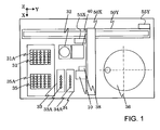
- Fig. 1 is a plan view showing the configuration of the automatic analyzer equipped with the dispensing device in accordance with the first embodiment of the present invention.
- a plurality of tips 31 are held by a tip holding part 31A.
- the tip 31, made of resin, is attached to a tip nozzle at the end of the dispensing device 10 which will be explained later.
- the detailed configuration of the dispensing device 10 will be described later referring to Figs. 2 - 4 .
- the tip 31 of the disposable type is used and replaced for each sample (test object).
- the used tip 31 is discarded to a waste container 32.
- a plurality of reagent containers 33 are held by a reagent container holding part 33A.
- the reagent containers 33 contain reagent solutions different from one another. From the reagent solution stored in each reagent container 33, a prescribed amount of the reagent solution is sucked in by the dispensing device 10. Meanwhile, a plurality of sample containers 34 are held by a sample container holding part 34A. Each sample container 34 contains a sample solution as a target of the inspection. From the sample solution stored in each sample container 34, a prescribed amount of the sample solution is sucked in by the dispensing device 10.
- a plurality of reaction containers 35 are held by a reaction container holding part 35A. Into each reaction container 35, the reagent liquid and the sample solution which have been sucked in by the dispensing device 10 are discharged.
- An X arm 50X is attached to a Y rail 50Y to be movable in a Y direction.
- a Y-axis movement mechanism 55Y including a stepping motor as a driving source, moves the X arm 50X in the Y direction along the Y rail 50Y.
- the dispensing device 10 and a gripper 38 are attached to the X arm 50X.
- An X-axis movement mechanism 55X including a stepping motor as a driving source, moves the dispensing device 10 and the gripper 38 in an X direction along the X arm 50X.
- the dispensing device 10 and the gripper 38 are also movable in a Z direction.
- the dispensing device 10 is positioned over a prescribed one of the tips 31 in the tip holding part 31A by moving the X arm 50X and the dispensing device 10 by operating the Y-axis movement mechanism 55Y and the X-axis movement mechanism 55X. Then, the dispensing device 10 descends in the Z direction, by which the tip 31 is attached to a tip nozzle at the end of the dispensing device 10 by press fitting.
- the dispensing device 10 is positioned over a prescribed one of the reagent containers 33 in the reagent container holding part 33A by moving the X arm 50X and the dispensing device 10 by operating the Y-axis movement mechanism 55Y and the X-axis movement mechanism 55X. Then, the dispensing device 10 descends in the Z direction, by which the tip 31 at the end of the dispensing device 10 is inserted into the reagent container 33. At this position, a prescribed amount of the reagent solution is sucked in from the reagent container 33.
- the dispensing device 10 is positioned over a prescribed one of the reaction containers 35 in the reaction container holding part 35A by moving the X arm 50X and the dispensing device 10 by operating the Y-axis movement mechanism 55Y and the X-axis movement mechanism 55X. Then, the dispensing device 10 descends in the Z direction, by which the tip 31 at the end of the dispensing device 10 is inserted into the reaction container 35. At this position, the reagent solution which has been sucked in is discharged into the reaction container 35.
- the dispensing device 10 is positioned over the waste container 32 by moving the X arm 50X and the dispensing device 10 by operating the Y-axis movement mechanism 55Y and the X-axis movement mechanism 55X. At this position, the dispensing device 10 discards the used tip 31 to the waste container 32.
- the dispensing device 10 is positioned over a prescribed one of the tips 31 in the tip holding part 31A by moving the X arm 50X and the dispensing device 10 by operating the Y-axis movement mechanism 55Y and the X-axis movement mechanism 55X. Then, the dispensing device 10 descends in the Z direction, by which the tip 31 is attached to the tip nozzle at the end of the dispensing device 10 by press fitting.
- the dispensing device 10 is positioned over a prescribed one of the sample containers 34 in the sample container holding part 34A by moving the X arm 50X and the dispensing device 10 by operating the Y-axis movement mechanism 55Y and the X-axis movement mechanism 55X. Then, the dispensing device 10 descends in the Z direction, by which the tip 31 at the end of the dispensing device 10 is inserted into the sample container 34. At this position, a prescribed amount of the sample solution is sucked in from the sample container 34.
- the dispensing device 10 is positioned over the aforementioned reaction container 35 in the reaction container holding part 35A (into which the reagent solution has been discharged) by moving the X arm 50X and the dispensing device 10 by operating the Y-axis movement mechanism 55Y and the X-axis movement mechanism 55X. Then, the dispensing device 10 descends in the Z direction, by which the tip 31 at the end of the dispensing device 10 is inserted into the reaction container 35. At this position, the sample solution which has been sucked in is discharged into the reaction container 35.
- the dispensing device 10 is positioned over the waste container 32 by moving the X arm 50X and the dispensing device 10 by operating the Y-axis movement mechanism 55Y and the X-axis movement mechanism 55X. At this position, the dispensing device 10 discards the used tip 31 to the waste container 32.
- the gripper 38 is positioned over the aforementioned reaction container 35 in the reaction container holding part 35A (into which the reagent solution and the sample solution have been discharged) by moving the X arm 50X and the gripper 38 by operating the Y-axis movement mechanism 55Y and the X-axis movement mechanism 55X.
- the gripper 38 descends, holds the reaction container 35, and ascends with the reaction container 35.
- the gripper 38 is moved to a position over an incubator 40 by operating the Y-axis movement mechanism 55Y and the X-axis movement mechanism 55X. Then, the gripper 38 descends and sets the reaction container 35 on the incubator 40.
- reaction container 35 is held by the gripper 38 and is transferred to a detection unit 36 by operating the Y-axis movement mechanism 55Y and the X-axis movement mechanism 55X.
- the detection unit 36 determines the amounts of ingredients of the reaction solution (quantitative analysis).
- a type of genome sequences as the target of the quantitative analysis are marked with a fluorescent pigment and corresponding fluorescence intensity is measured by the detector 36.
- Fig. 2 is a front view showing the configuration of the dispensing device in accordance with the first embodiment of the present invention.
- Fig. 3 is a front view showing the internal configuration of the dispensing device in accordance with the first embodiment of the present invention.
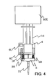
- Fig. 4 is a side view showing the configuration of the dispensing device in accordance with the first embodiment of the present invention (right side view of Fig. 2 ).
- the same reference characters represent the same component.
- a Z-axis movement mechanism 55Z is attached to the X arm 50X.
- the Z-axis movement mechanism 55Z is equipped with a stepping motor as a driving source and a feed screw.
- a syringe base 12 of the dispensing device 10 is fixed to a nut part of the feed screw.
- the dispensing device 10 is mainly composed of an upper fixed unit 10A and a lower movable unit 10B.
- the upper fixed unit 10A and the lower movable unit 10B are moved together in the Z-axis direction by the Z-axis movement mechanism 55Z.
- the end of the lower movable unit 10B (lower end of the tip 31 in the example shown in Fig. 2 ) makes contact with a container, etc., the lower movable unit 10B can independently move relative to the upper fixed unit 10A.
- the upper fixed unit 10A mainly includes a hollow-body syringe 4, a driving source 6, a power converter 7, the syringe base 12, a plunger 13 and a syringe fixation member 14.
- the driving source 6, including a stepping motor, etc., is fixed to the syringe base 12.
- the converter 7 includes a ball screw 7a and a moving member 7b engaged with the ball screw 7a.
- the ball screw 7a is driven and rotated by the driving source 6, the motion is converted to linear motion and the moving member 7b moves in the Z-axis direction.
- a linear guide may be attached to the syringe base 12.
- the plunger 13 is fixed to the moving member 7b.
- the plunger 13, inserted into the syringe 4, moves to and fro inside the syringe 4 according to the normal/reverse rotation of the driving source 6. Since the upper part of the syringe 4 (i.e., the sliding interface between the syringe 4 and the plunger 13) is kept hermetic by a member like a seal piece, air does not leak out.
- the lower end of the syringe 4 is hermetically fixed to the syringe fixation member 14. As shown in Fig. 3 , a hollow part 4A inside the syringe 4 and a channel 14A formed inside the syringe fixation member 14 are connected with each other.
- the syringe fixation member 14 is fixed to the syringe base 12.
- An upper photo interrupter 9U for tip attachment detection and a lower photo interrupter 9L for the jamming detection are fixed on the syringe base 12.
- the lower movable unit 10B mainly includes a tip holding part 5, a connection rod 3 and a spring 15.
- a tip nozzle 8 for firmly holding the replaceable tip 31 attached thereto by press fitting, is attached integrally to the tip holding part 5.
- connection rod 3 is made up of two rods 3A and 3B as shown in Fig. 4 .
- the lower part of the connection rod 3 is fixed to the tip holding part 5.
- the upper part of the connection rod 3 is inserted into through holes formed in the syringe fixation member 14 so that the connection rod 3 can move up and down.
- the sliding interfaces between the connection rod 3 and the syringe fixation member 14 are provided with linear bearings for excellent lubrication. It is also possible to place members excelling in lubrication (e.g., fluoroplastic) instead of the linear bearings.
- a channel 5A is formed inside the tip holding part 5 as shown in Fig. 3 .
- the channel 5A of the tip holding part 5 and the channel 14A of the syringe fixation member 14 are hermetically connected with each other by a hollow connection tube 1.
- a through hole is formed from the upper end to the lower end of the tip 31.
- the channel 5A of the tip holding part 5 is connected with the through hole inside the tip 31 via a hole inside the tip nozzle 8. Therefore, the hollow part 4A of the syringe 4 is connected to an opening part at the end of the tip 31 via the channel 14A of the syringe fixation member 14, the hollow part of the connection tube 1, the channel 5A of the tip holding part 5 and the through hole inside the tip 31.
- the connected space from the hollow part 4A of the syringe 4 to the opening part at the end of the tip 31 is filled with air as the pressure-transmitting fluid. Therefore, if the plunger 13 moves upward when the end of the tip 31 has been inserted into the reagent solution inside the reagent container, for example, the pressure inside the connected space drops and the reagent solution can be sucked in through the end of the tip 31. In contrast, if the plunger 13 moves downward when the reagent solution has been sucked into the tip 31, the pressure inside the connected space rises and the reagent solution previously sucked into the tip 31 is discharged from the opening part at the end of the tip 31.
- sample solution reagent solution
- connection tube 1 is made of a material enabling bendability/flexibly (e.g., fluoroplastic). Thus, the connected space described above is not blocked up even when the tip holding part 5 moves up and down.
- the shape of the connection tube 1 is not particularly restricted as long as the capacity inside the connection tube 1 does not change much between the normal state and the bent state. For example, either a cylindrical tube with a smooth surface or a bellows tube may be used.
- a stopper part 3U is attached to the upper end of the connection rod 3.
- the stopper part 3U contacts the top of the syringe fixation member 14 and thereby prevents the tip holding part 5 from descending further.
- the tip holding part 5, which has descended due to its own weight, is situated at the lowest point in its movable range due to the restriction on its downward movement by the stopper part 3U.
- the spring 15 is arranged between the syringe fixation member 14 and the tip holding part 5 to surround the connection rod 3.
- the stopper part 3U contacts the syringe fixation member 14 and the tip holding part 5 is suspended from the stopper part 3U.
- the lower end of the spring 15 contacts the top of the tip holding part 5 and a gap is formed between the upper end of the spring 15 and the syringe fixation member 14.
- the lower end of the spring 15 contacts the upper end of the lower movable unit 10B and the upper end of the spring 15 has a noncontact spring length to the lower end of the upper fixed unit 10A.
- the lower movable unit 10B stops the downward movement when the lower end of the tip 31 (if the tip 31 has been attached) or the lower end of the tip nozzle 8 (if the tip 31 has not been attached) makes contact with a container or an obstacle.
- the upper fixed unit 10A continues the downward movement, a gap between the lower end of the upper fixed unit 10A and the upper end of the lower movable unit 10B decreases.
- the gap between the lower end of the upper fixed unit 10A and the upper end of the lower movable unit 10B decreases further, with the spring 15 being gradually compressed by the driving force moving the upper fixed unit 10A downward.
- the lower movable unit 10B is connected to the upper fixed unit 10A while also being relatively movable with respect to the upper fixed unit 10A. Further, the interior space of the syringe 4 attached to the upper fixed unit 10A and the interior space of the tip nozzle attached to the lower movable unit 10B are connected with each other by the connection tube 1 having flexibility.
- the driving source 6, the converter 7, the syringe base 12, the plunger 13 and the syringe fixation member 14 are made of metal, whereas the syringe 4 is made of resin.
- the tip holding part 5, the connection rod 3 and the spring 15 as the components of the lower movable unit 10B are made of metal. Since the tip holding part 5 is smaller than each component of the upper fixed unit 10A, the weight of the lower movable unit 10B is as light as approximately 1/20 of that of the upper fixed unit 10A.
- the lower movable unit 10B can stop its movement even when the lower end of the tip 31 makes slight contact with a container or an obstacle. Further, since there is the gap between the syringe fixation member 14 and the upper end of the spring 15, the upper fixed unit 10A is moved quickly even by weak downward driving force until the syringe fixation member 14 contacts the upper end of the spring 15. Furthermore, when the tip 31 is attached to the tip nozzle 8 by press fitting, the spring 15 is compressed between the syringe fixation member 14 and the tip holding part 5 and the biasing force of the spring 15 in this phase serves as the press fitting load on the tip 31. Since the biasing force of the spring 15 can be kept at a constant level, the press fitting load can easily be adjusted and set at an intended value (e.g., 3kgf).
- an intended value e.g., 3kgf
- connection rod 3 may also be fixed to the syringe fixation member 14 to be slidable with respect to the tip holding part 5.
- the photo interrupters 9U and 9L and a detection plate 11 are provided for detecting the status of the gap between the syringe fixation member 14 and the tip holding part 5.
- the photo interrupters 9U and 9L are attached to the syringe base 12 at positions apart from each other in the Z-axis direction.
- the photo interrupter 9U includes a light-emitting unit 9a (e.g., light-emitting diode) and a photoreceptor unit 9b (e.g., photodiode) arranged across a gap.
- the photo interrupter 9L also has a similar configuration.
- the detection plate 11 moves between the gap between the light-emitting unit and the photoreceptor unit of the photo interrupter 9U and the gap between the light-emitting unit and the photoreceptor unit of the photo interrupter 9L.
- the detection plate 11 has a notch part 11a and a non-notch part 11b (including two non-notch parts).
- the photo interrupter 9U remains in its ON state when the non-notch part 11b does not exist in the gap of the photo interrupter 9U.
- the photo interrupter 9L remains in its ON state when the notch part 11a exists in the gap of the photo interrupter 9L.
- the photo interrupter 9U remains in its OFF state when the non-notch part 11b exists in the gap of the photo interrupter 9U.
- the photo interrupter 9L remains in its OFF state when the notch part 11a does not exist in the gap of the photo interrupter 9L.
- the tip holding part 5 In the state shown in Fig. 2 , the tip holding part 5 is situated at its lowest position due to its own weight. In this state, both the photo interrupters 9U and 9L are ON. When the distance between the tip holding part 5 and the syringe fixation member 14 decreases and the distance between the upper end of the spring 15 and the lower end of the syringe fixation member 14 decreases to 0, the photo interrupter 9L turns OFF. Further, when the spring 15 is compressed to its shortest length and the distance between the tip holding part 5 and the syringe fixation member 14 reaches the minimum, the photo interrupter 9U turns OFF. Therefore, the status of the gap between the syringe fixation member 14 and the tip holding part 5 can be detected from the ON/OFF states of the photo interrupters 9U and 9L.
- detecting means including the photo interrupters 9U and 9L and the detection plate 11 detects the relative movement between the upper fixed unit 10A and the lower movable unit 10B.
- the detecting means detects that the tip 31 attached to the tip nozzle 8 has contacted another object.
- the detecting means detects that the tip 31 has been attached to the tip nozzle 8
- a control unit (CU) 100 outputs a driving/stopping control signal to the Z-axis movement mechanism 55Z and thereby controls the driving/stopping of the stepping motor in the Z-axis movement mechanism 55Z.
- the control unit 100 controls the driving/stopping of the Z-axis movement mechanism 55Z based on the ON/OFF states of the photo interrupters 9U and 9L.
- FIGs. 5 - 7 are schematic diagrams for explaining the tip attaching operation of the dispensing device in accordance with the first embodiment of the present invention, wherein reference characters identical with those in Figs. 2 - 4 represent the same components as in Figs. 2 - 4 .
- a tip 31 has been held by the tip holding part 31A. While only one tip 31 is shown in the illustrated example, a plurality of tips 31 are actually held by the tip holding part 31A.
- the dispensing device 10 is positioned over one of the tips 31 by the operation of the Y-axis movement mechanism 55Y and the X-axis movement mechanism 55X shown in Fig. 1 . In this state, the dispensing device 10 is lowered in the Z-axis direction by operating the Z-axis movement mechanism 55Z.
- Fig. 6 shows the state in which the syringe base 12 has moved downward and the tip nozzle 8 has been inserted into the upper opening of the tip 31.
- the descent of the tip holding part 5 stops, whereas the descent of the upper fixed unit 10A (including the syringe fixation member 14) continues. Consequently, the gap between the upper end of the spring 15 and the syringe fixation member 14 decreases.
- Fig. 6 shows the state in which the gap has decreased to 0.
- the non-notch part 11b of the detection plate 11 is situated in the gap of the lower photo interrupter 9L and the output signal of the lower photo interrupter 9L turns OFF. This allows the control unit 100 shown in Fig. 2 to detect that the end of the tip nozzle 8 has contacted the tip 31 (jamming detection).
- the tip 31 has not been held by the tip nozzle 8 yet in the state of Fig. 6 , and thus the syringe fixation member 14 continues descending due to the operation of the Z-axis movement mechanism 55Z.
- the spring 15 is compressed between the tip holding part 5 and the syringe fixation member 14 as shown in Fig. 7 .
- the end of the tip nozzle 8 is pressed into the upper opening (inner wall) of the tip 31.
- Fig. 7 shows the state in which the spring 15 has been compressed to its minimum length.
- the non-notch part 11b of the detection plate 11 is situated in the gap of the upper photo interrupter 9U and the output signal of the upper photo interrupter 9U turns OFF. This allows the control unit 100 shown in Fig. 2 to detect that the tip 31 has been pressed into the end of the tip nozzle 8, that is, the tip has been attached.
- the detecting means including the detection plate 11 and the photo interrupters 9 is capable of detecting the relative movement between the upper fixed unit 10A and the lower movable unit 10B.
- the photo interrupter 9L detects that the end of the tip nozzle 8 has contacted the tip 31.
- the upper photo interrupter 9U detects that the tip 31 has been attached to the tip nozzle 8.
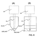
- FIGs. 8 and 9 are schematic diagrams for explaining the liquid suction/discharge operation of the dispensing device in accordance with the first embodiment of the present invention.
- the control unit 100 outputs a rotation control signal to the driving source 6 and thereby drives and rotates the stepping motor, etc. of the driving source 6.
- the plunger 13 moves upward in the Z-axis direction and generates pressure in the space inside the syringe 4.
- the generated pressure is transmitted through the connected space inside the syringe 4, the syringe fixation member 14, the connection tube 1, the tip holding part 5 and the tip nozzle 8, by which liquid is sucked in through the end of the tip 31.
- the driving source 6 rotates in the reverse direction
- the plunger 13 moves downward in the Z-axis direction, by which the liquid sucked into the tip 31 is discharged.
- connection tube 1 is bendable, the pressure caused by the up-and-down movement of the plunger can be reliably transmitted to the tip 31 even when the tip holding part 5 is in contact with another object (foreign object).
- Fig. 8 shows the state in which the tip 31 of the dispensing device 10 has been inserted into a reagent container 33 or sample container 34.
- the container (33, 34) has a V-shaped bottom as shown in Fig. 8 (A) to reduce the amount of liquid that can not be sucked in and remains in the container.
- Fig. 8 (B) is a right side view of Fig. 8(A) .
- the end of the tip 31 contacts the bottom of the container (33, 34).
- the descent of the tip holding part 5 stops, whereas the descent of the upper fixed unit (including the syringe fixation member 14) continues. Consequently, the gap between the upper end of the spring 15 and the syringe fixation member 14 decreases.
- the output signal of the photo interrupter 9L turns OFF. This allows the control unit 100 to detect that the tip 31 has contacted the bottom of the container 33 or 34 (jamming detection).
- the control unit 100 Upon the detection of the contact of the tip 31 with the bottom of the container (33, 34), the control unit 100 outputs the rotation control signal to the driving source 6 and thereby drives and rotates the stepping motor, etc. of the driving source 6.
- the plunger 13 moves upward in the Z-axis direction and generates pressure in the space inside the syringe 4. Due to the generated pressure, the liquid (reagent solution 33B, sample solution 34B) inside the container (33, 34) is sucked in through the end of the tip 31.
- This jamming detection function makes it possible to suck in liquid while pressing the tip end (end of the tip 31) of the dispensing device against the bottom of the container containing the liquid (reagent, sample). Therefore, the liquid can be sucked in efficiently even when the amount of the liquid existing in the container is small.
- the deformation of the tip 31 and the container which are relatively soft (made of polypropylene as plastic having high chemical resistance, for example), is large with respect to the load.
- the tip holding part 5 can be designed lightweight and the deformation of the tip and the container upon contact can be reduced in this embodiment, an intended amount of liquid can be sucked in correctly while securing a flow channel around the opening at the tip end by the deformation of the tip and the container.
- Fig. 9 shows the shape of another container (33', 34').
- the container (33', 34') has a conical mortar-like bottom shape.
- the flow channel can be secured by performing the sucking operation with the central axes of the tip 31 and the container (33', 34') shifted from each other.
- the bottom shape of the container is not restricted to the conical mortar-like shape; a container with a round bottom shape may also be used.
- Fig. 9(B) is a right side view of Fig. 9(A) .
- the volume (capacity) of the connected space from the inside of the syringe 4 to the tip 31 is desired to be as smaller as possible compared to the intended amount of the sucked/discharged liquid.
- the syringe 4 and the tip 31 can be arranged close to each other in this embodiment since the syringe 4 is fixed to the syringe fixation member 14, the tip 31 is attached to the tip holding part 5, the distance between the syringe fixation member 14 and the tip holding part 5 can be as short as approximately the total length of the spring 15. Therefore, the volume (capacity) of the channel inside the connection tube 1 connecting the syringe fixation member 14 and the tip holding part 5 can be set small and high dispensing accuracy can be realized.
- metal such as aluminum can be used as the material of the tip holding part 5
- lightweight material such as plastic can also be used in place of metal.
- the weight of the lower movable unit 10B can be reduced further by use of the lightweight material.
- the dispensing device of this embodiment is applicable also to cases where liquid is used as the pressure-transmitting fluid.
- the tip holding part 5 movable part
- the sensitivity of the jamming detection can be increased, as well as reducing the impact caused by collision.
- the distance of displacement until the upper end of the spring 15 contacts the syringe fixation member 14 can be used as displacement for the jamming detection.
- the distance of displacement until the upper end of the spring 15 contacts the syringe fixation member 14 can be used as displacement for the jamming detection.
- the depressing force caused by the weight of the tip holding part 5 is applied to the tip 31.
- both the impact on the foreign object and the impact on the dispensing device upon collision can be reduced. Since the occurrence of even a slight load can be detected, high detection accuracy of the jamming detection function can be achieved.
- connection rod and the spring are used as the mechanism for moving the tip holding part 5 relative to the syringe base 12, a sliding mechanism such as a linear slider can also be used.
- the spring is used for generating the biasing force in the direction obstructing the approximation of the tip holding part 5 to the syringe base 12, other elastic materials such as rubber can also be used.
- the relative positional relationship between the tip holding part 5 and the syringe base 12 equipped with the syringe 4 is not restricted to this example.
- the syringe base 12 may also be arranged so as to orient the major axis of the syringe 4 in a horizontal direction and so as to be orthogonal to the axis of the tip holding part 5 arranged to orient the major axis of the tip 31 in the vertical direction.
- the tip and the tip holding part 5 may also be fixed or integrated.
- connection tube 1 an elastic hollow-body member
- the driving source e.g., stepping motor
- the mechanism for converting the driving force e.g., ball screw
- the weight of the tip holding part 5 as the movable part can be reduced and a greater upward displacement of the tip holding part 5 with respect to a slighter load can be realized. Since even a slight load can be detected, high detection accuracy for the contact of the tip holding part 5 can be achieved. Furthermore, since the clearance against the deforming load on the tip and the mechanism can also be set large, deterioration in the dispensing performance and malfunction of the mechanism caused by the deformation can be prevented.
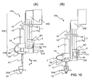
- FIG. 10 and 11 are front views showing the configuration of the dispensing device in accordance with the second embodiment of the present invention, wherein reference characters identical with those in Fig. 2 represent the same components as in Fig. 2 .
- the basic configuration of the upper fixed unit 10A and the lower movable unit 10B is similar to that shown in Fig. 2 .
- the lower movable unit 10B is connected to the upper fixed unit 10A while also being relatively movable with respect to the upper fixed unit 10A.
- the interior space of the syringe 4 attached to the upper fixed unit 10A and the interior space of the tip nozzle attached to the lower movable unit 10B are connected with each other by the connection tube 1 having flexibility.
- the configuration of the part connecting the upper fixed unit 10A and the lower movable unit 10B is different.
- the syringe fixation member 14 of the upper fixed unit 10A and the tip holding part 5 of the lower movable unit 10B are connected with each other by an elastic member 29.
- an elastic member 29 For example, relatively soft rubber material such as silicone rubber is used as the elastic member 29.
- the elastic member 29 allows for displacement of the tip holding part 5 relative to the syringe fixation member 14 both in the Z-axis direction and in the Y-axis direction. While displacement in the X-axis direction is also possible, this explanation will be given assuming that the jamming detection is executed using a detection plate 11A and photo interrupters 9U' and 9L' for detecting the displacement in the Z-axis direction and the Y-axis direction.
- a reagent container 33 has been held by the reagent container holding part 33A. While only one reagent container 33 is shown in the illustrated example, a plurality of reagent containers 33 are actually held by the reagent container holding part 33A. Incidentally, the following explanation holds also for cases where not a reagent container but a sample container is used.
- Fig. 10(A) shows a state in which the dispensing device 10a has moved downward in the dispensing operation.
- the central axis of the tip 31 has shifted rightward in Fig. 10(A) with respect to the central axis of the reagent container 33.
- the dispensing device 10a is lowered by the Z-axis movement mechanism 55Z.
- the output of the photo interrupter 9L is ON since an opening part 11c of the detection plate 11A exists in the gap of the photo interrupter 9L.
- the output of the photo interrupter 9U is also ON since the detection plate 11A does not exist in the gap of the photo interrupter 9U.
- the end of the tip 31 makes contact with an inclined inner surface of the reagent container 33. Since the lower movable unit 10B receives leftward force in Fig. 10(A) due to the contact, the elastic member 29 deforms and moves leftward. Meanwhile, the upper fixed unit 10A continues the downward movement. Consequently, a non-opening part 11b of the detection plate 11A comes to the gap of the photo interrupter 9L and the output of the photo interrupter 9L turns OFF, by which the jamming can be detected. At this point, the upper photo interrupter 9U remains ON. The end of the tip 31 is situated at the lowest part of the reagent container 33, which makes it possible to suck in the reagent remaining at the bottom of the reagent container 33.
- the elastic member 29 deforms until both the photo interrupters 9U and 9L become OFF, by which the attachment of the tip can be detected.
- Fig. 11 shows a state in which the X rail 50X is being driven in the Y-axis direction by the Y-axis movement mechanism 55Y shown in Fig. 1 after the dispensing device 10a has been moved downward.
- the dispensing device 10a When the dispensing device 10a is moved in the Y-axis direction (rightward in Fig. 11 as shown in Fig. 11(B) ) after being moved downward, the end of the tip 31 makes contact with the obstacle 42. Due to the contact, the lower movable unit 10B stops moving and the upper fixed unit 10A continues moving in the Y-axis direction, by which the lower movable unit 10B is moved upward. Consequently, the non-opening part 11b of the detection plate 11A comes to the gap of the photo interrupter 9L and the output of the photo interrupter 9L turns OFF, by which the jamming can be detected.
- the impact caused by the collision with the obstacle can be reduced in the vertical and horizontal directions, while increasing the jamming detection sensitivity by employing the lightweight tip holding part 5. Further, by making the tip actively contact the liquid container, high dispensing accuracy can be secured and the scattering of the liquid can be prevented.
- the detecting means including the detection plate 11A and the photo interrupters 9 is capable of detecting the relative movement between the upper fixed unit 10A and the lower movable unit 10B.
- the photo interrupter 9L detects that the tip 31 attached to the tip nozzle 8 has contacted another object (container, obstacle, etc.).
- the upper photo interrupter 9U detects that the tip 31 has been attached to the tip nozzle 8.
- connection tube 1 an elastic hollow-body member
- the driving source e.g., stepping motor
- the mechanism for converting the driving force e.g., ball screw
- the weight of the tip holding part 5 as the movable part can be reduced and a greater upward displacement of the tip holding part 5 with respect to a slighter load can be realized. Since even a slight load can be detected, high detection accuracy for the contact of the tip holding part 5 can be achieved. Furthermore, since the clearance against the deforming load on the tip and the mechanism can also be set large, deterioration in the dispensing performance and malfunction of the mechanism caused by the deformation can be prevented.
- FIG. 12 is a front view showing the configuration of the dispensing device in accordance with the third embodiment of the present invention, wherein reference characters identical with those in Fig. 2 represent the same components as in Fig. 2 .
- Fig. 13 is a right side view of Fig. 12 .
- the basic configuration of the upper fixed unit 10A and the lower movable unit 10B is similar to that shown in Fig. 2 .
- the lower movable unit 10B is connected to the upper fixed unit 10A while also being relatively movable with respect to the upper fixed unit 10A.
- the interior space of the syringe 4 attached to the upper fixed unit 10A and the interior space of the tip nozzle attached to the lower movable unit 10B are connected with each other by the connection tube 1 having flexibility.
- the configuration of the part connecting the upper fixed unit 10A and the lower movable unit 10B is different.
- the syringe fixation member 14 of the upper fixed unit 10A and the tip holding part 5 of the lower movable unit 10B are connected with each other by a hinge 23 and two springs 28.
- the hinge 23 is capable of rotating around its rotation center and thereby changing the lean of the lower movable unit 10B.
- the lower movable unit 10B rotates around the hinge 23 and leans along the inner wall of the container 33 as shown in Fig. 12(B) , by which the tip holding part 5 is set at an appropriate angle (hereinafter referred to as "edging").
- edging an appropriate angle
- the angle of the edging can be controlled by the contact of the tip 31 with the liquid container or the like.
- the tip can be inserted into an obliquely placed container 33 (e.g., centrifuge) and the contents of the container can be sucked in or liquid can be discharged into the container without scattering the liquid to the outside of the container. Therefore, automation of the dispensing of liquid from a centrifuge can be carried out with ease and reliability.
- container 33 e.g., centrifuge
- the elastic member 28 is employed for the dispensing device and the elastic member 28 sets the static position of the tip holding part 5 in the noncontact state in the example of Fig. 12 , it is also possible to leave out the elastic member 28 and let the weight of the tip holding part 5 set the static position.
- the jamming detection is executed using a detection plate 11B and a photo interrupter 9 shown in Fig. 13 .
- the detection plate 11B is attached to the lower movable unit 10B, while the photo interrupter 9 is attached to the upper fixed unit 10A.
- the detection plate 11B has been inserted in the gap of the photo interrupter 9 and thus the photo interrupter 9 is OFF.
- the detection plate 11B goes out of the gap of the photo interrupter 9 and the photo interrupter 9 turns ON, by which the jamming can be detected.
- the detecting means including the detection plate 11B and the photo interrupter 9 is capable of detecting the relative movement between the upper fixed unit 10A and the lower movable unit 10B.
- the photo interrupter 9 detects that the tip 31 attached to the tip nozzle 8 has contacted another object (container, obstacle, etc.) and has been set at a prescribed lean angle (edging).
- connection tube 1 an elastic hollow-body member
- the driving source e.g., stepping motor
- the mechanism for converting the driving force e.g., ball screw
- the weight of the tip holding part 5 as the movable part can be reduced and a greater upward displacement of the tip holding part 5 with respect to a slighter load can be realized. Since even a slight load can be detected, high detection accuracy for the contact of the tip holding part 5 can be achieved. Furthermore, since the clearance against the deforming load on the tip and the mechanism can also be set large, deterioration in the dispensing performance and malfunction of the mechanism caused by the deformation can be prevented.
- the liquid discharged from the tip can be prevented from partially adhering to the tip end and remaining without being pipetted into the container.
- actively edging i.e., giving a lean angle to
- the contamination between the tip and the liquid/container can be avoided.
- the liquid is injected in a wide range from the tip end when the liquid discharging speed is high, by which problems such as deterioration in the dispensing accuracy and scattering of the liquid can be avoided.
- FIG. 14 is front views showing the configuration of the dispensing device in accordance with the fourth embodiment of the present invention, wherein reference characters identical with those in Fig. 2 represent the same components as in Fig. 2 .
- the basic configuration of the upper fixed unit 10A and the lower movable unit 10B is similar to that shown in Fig. 2 .
- the configuration of the part connecting the upper fixed unit 10A and the lower movable unit 10B is different.
- the syringe fixation member 14 of the upper fixed unit 10A and the tip holding part 5 of the lower movable unit 10B are connected with each other by a hinge 23.
- the hinge 23 is capable of rotating around its rotation center and thereby changing the lean of the lower movable unit 10B.
- the dispensing device is further equipped with a cam 22 which is rotated by a motor 21. According to the rotation of the cam 22, a push rod 24 in contact with the cam surface pushes out the tip holding part 5, by which the tip holding part 5 is leaned around the hinge 23 and the edging of the tip holding part 5 is conducted.
- the angle of the edging can be controlled when the tip 31 contacts with the liquid container or the like.
- the dispensing device of this embodiment is similarly equipped with the detection plate 11B and the photo interrupter 9 shown in Fig. 13 (although not shown in Fig. 14 ), with which the jamming detection is possible.
- the jamming detection can also be executed based on the rotation angle of the cam 22 rotated by the motor 21.
- connection tube 1 an elastic hollow-body member
- the driving source e.g., stepping motor
- the mechanism for converting the driving force e.g., ball screw
- the weight of the tip holding part 5 as the movable part can be reduced and a greater upward displacement of the tip holding part 5 with respect to a slighter load can be realized. Since even a slight load can be detected, high detection accuracy for the contact of the tip holding part 5 can be achieved. Furthermore, since the clearance against the deforming load on the tip and the mechanism can also be set large, deterioration in the dispensing performance and malfunction of the mechanism caused by the deformation can be prevented.
- the liquid discharged from the tip can be prevented from partially adhering to the tip end and remaining without being pipetted into the container.
- the contamination between the tip and the liquid/container can be avoided.
- the liquid is injected in a wide range from the tip end when the liquid discharging speed is high, by which problems such as deterioration in the dispensing accuracy and scattering of the liquid can be avoided.
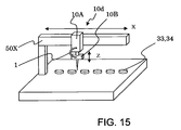
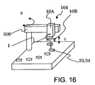
- Figs. 15 - 17 are perspective views of the modifications of the automatic analyzer shown in Fig. 1 .
- an upper fixed unit 10A including a syringe is attached to an X arm 50X and can be driven in the X direction shown in Fig. 17 .
- a lower movable unit 10B includes a tip holding part. The tip holding part is connected with the inside of the syringe of the upper fixed unit 10A by a connection tube 1.
- the upper fixed unit 10A includes a mechanism for driving the lower movable unit 10B in the Z direction.
- the dispensing device 10d comprising the upper fixed unit 10A and the lower movable unit 10B is movable along the X arm 50X over liquid containers (reagent containers 33, sample containers 34) aligned in the X direction.
- the dispensing device 10d shown in Fig. 5 is supported by a ⁇ arm 50 ⁇ .
- the ⁇ arm 50 ⁇ is capable of rotating in the ⁇ direction shown in Fig. 16 .
- the upper fixed unit 10A includes a mechanism for driving the lower movable unit 10B in the Z direction.
- a dispensing device 10e can be driven in the X direction with respect to an X arm 50X.
- the X arm 50X can be driven in the Z direction with respect to a Z arm 50Z.
- the dispensing device 10e comprises an upper fixed unit 10A and a lower movable unit 10B.
- the lower movable unit 10B can be driven in the Y direction with respect to the upper fixed unit 10A.
- the driving in the Y direction is performed by a linear motor, etc. installed in the upper fixed unit 10A.
- liquid containers (reagent containers 33, sample containers 34) are arranged to be apart in the X direction and close in the Y direction
- the movement in the X direction is performed by the X arm capable of high-speed driving and the movement in the Y direction is performed by the moving mechanism installed in the upper fixed unit 10A.
- the movement in the Y direction (light load and short distance compared to the movement in the X direction) can be implemented by a relatively small-scale moving mechanism, the total weight of the dispensing device can be reduced. Further, since the resolution of the driving in the Y direction can be made finer, the density of the arrangement of the liquid containers in the Y direction can be increased and the dispensing device can be downsized.
- the lower movable unit 10B is connected to the upper fixed unit 10A while also being relatively movable with respect to the upper fixed unit 10A.
- the interior space of the syringe 4 attached to the upper fixed unit 10A and the interior space of the tip nozzle attached to the lower movable unit 10B are connected with each other by the connection tube 1 having flexibility.
- a mechanism that drives only the lower movable unit 10B (including the lightweight tip holding part), instead of driving the whole of the dispensing device in the Z-axis direction, is employed, and thus the mechanism can be designed lightweight. Since the operating time can be shortened by the weight reduction, the time necessary for the dispensing (in a dispensing device) and analysis (in an analyzer) can be shortened.
- Fig. 18 is a plan view showing the configuration of the automatic analyzer equipped with the dispensing device in accordance with the fifth embodiment of the present invention, wherein reference characters identical with those in Fig. 1 represent the same components as in Fig. 1 .
- the automatic analyzer explained referring to Fig. 1 uses air as the fluid for transmitting the pressure generated in the syringe.
- the dispensing devices which have been shown in Fig. 2 , etc. are characterized in that the dispensing device comprises the upper fixed unit and the lower movable unit, the two units are connected with each other by a connection tube, the connection tube is used as the channel for transmitting the pressure of the fluid, and a flexible tube is used as the connection tube. Therefore, the idea of the dispensing devices shown in Fig. 2 , etc. is applicable also to an automatic analyzer for analyzing blood, etc. that uses liquid as the pressure-transmitting fluid.
- reagent containers 33 are mounted on a reagent disk 33A' and reaction containers 35 are mounted on a reaction disk 35A'.
- a detection unit 36' is placed on the circumference of the reaction disk 35A'.
- a cleaning liquid pump 63 is connected to the dispensing device 10f by a cleaning liquid tube 61.
- a cleaning port 64 is placed within the moving range of the dispensing device 10f.
- the dispensing device 10f is attached to an X arm 50X to be movable in the X direction by an X-axis movement mechanism 55X.
- the X arm 50X is attached to a Y rail 50Y to be movable in the Y direction by a Y-axis movement mechanism 55Y.
- the dispensing device 10f is movable also in the Z direction by a Z-axis movement mechanism 55Z.
- the automatic analyzer for analyzing blood, etc. uses a nozzle for the dispensing of liquid, without using the replaceable tips.
- the automatic analyzer is not equipped with the tip, the tip holding part, etc.
- the basic operation of the other components is similar to that explained referring to Fig. 1 .
- Fig. 19 is a front view showing the configuration of the dispensing device in accordance with the fifth embodiment of the present invention, wherein reference characters identical with those in Fig. 18 represent the same components as in Fig. 18 .
- the dispensing device 10f comprises a fixed unit 10A' and a movable unit 10B'.
- a syringe 4 as a component of the fixed unit 10A' and a nozzle 2 as a component of the movable unit 10B' are connected with each other by a connection tube 1 having flexibility.
- the movable unit 10B' is connected to the fixed unit 10A' while also being relatively movable with respect to the fixed unit 10A'.
- the interior space of the syringe 4 attached to the fixed unit 10A' and the interior space of the nozzle 2 attached to the movable unit 10B' are connected with each other by the connection tube 1 having flexibility.
- the left fixed unit 10A' includes a driving source 6 (fixed on a syringe base 12'), the syringe 4 and a valve 19.
- the driving source 6 moves a plunger 13 to and fro and thereby generates pressure inside the syringe 4.
- the cleaning liquid is introduced into the inside of the syringe 4 via the cleaning liquid tube 61 and the valve 19 as the pressure-transmitting fluid.
- a nozzle guide 16, a stopper 17 and a photo interrupter 9 for the jamming detection are fixed on the syringe base 12'.
- the right movable unit 10B' includes the nozzle 2, a spring 15, a spring holding part 18 and a detection plate 11.
- the nozzle 2 is held by the nozzle guide 16 to be movable to and fro (up and down).
- the connection tube 1 is connected to the upper end of the nozzle 2.
- the spring holding part 18 is attached to the nozzle 2.
- the spring 15 is arranged between the stopper 17 and the spring holding part 18 to surround the nozzle 2.
- the detection plate 11 is attached to the upper part of the nozzle 2.
- a spring having a small spring constant is employed as the spring 15 since the spring 15 is used for the jamming detection.
- the detecting means including the detection plate 11 and the photo interrupter 9 is capable of detecting the relative movement of the movable unit 10B' with respect to the fixed unit 10A'.
- the photo interrupter 9 detects that the nozzle 2 has contacted another object (container, obstacle, etc.).
- the dispensing device 10f is moved to the cleaning port 64.
- the nozzle 2 is washed and cleaned by opening the valve 19 and letting the cleaning liquid (supplied from the cleaning liquid pump 63) flow out through the nozzle 2. After the cleaning is finished, the valve 19 is closed.
- the dispensing device 10f is moved to a position over a selected sample container 34 and a prescribed amount of sample solution is sucked in by moving the plunger 13 downward by the driving source 6. Then, the dispensing device 10f is moved to a position over one reaction container 35 on the reaction disk 35A', descends until the photo interrupter 9 reacts, and discharges a prescribed amount of the sample solution. Thereafter, the dispensing device 10f is moved to the position of the cleaning port 64 and the nozzle 2 is washed and cleaned by opening the valve 19 and letting the cleaning liquid (supplied from the cleaning liquid pump 63) flow out through the nozzle 2.
- the dispensing device 10f is moved to a position over the reagent disk 33A' and sucks in a reagent solution from a selected reagent container 33. Then, the dispensing device 10f is moved to the aforementioned position of the reaction disk 35A' and discharges a prescribed amount of the reagent solution into the reaction container 35.
- the dispensing of a reagent is executed multiple times.
- the reaction disk 35A' periodically repeats rotation and stoppage. Optical detection is conducted when the reaction container 35 (into which the sample and the reagent have been pipetted) passes through the detection unit 36'. From the result of the optical detection, the concentration of a particular ingredient of the sample solution is calculated and outputted.
- the nozzle 2 is washed and cleaned on each execution of the dispensing. Therefore, high-precision analysis, free from contamination by other samples or reagents, can be performed without the need of using the tips. Consequently, low-cost analysis is made possible.
- each liquid is discharged after the nozzle 2 is lowered until the photo interrupter 9 reacts, the discharging of each liquid can be performed with the end of the nozzle 2 securely contacting the bottom of the reaction container 35. Thus, high-accuracy dispensing is possible.
- the lightweight nozzle 2 is movable with respect to the dispensing device 10f, the impact when the end of the nozzle 2 contacts the bottom of the reaction container 35 is weak and the damage to the reaction container is light. Effects of deformation/vibration of the reaction disk 35A' on the reaction/detection in other reaction containers can be minimized, which enables high-accuracy analysis.
- the syringe 4 and the connection tube 1 are filled with liquid having a lower expansion rate than gas and the amount of the discharge from the syringe 4 can be transmitted to the nozzle 2 correctly, the accuracy of the dispensing is high and high-accuracy analysis is possible.
- connection tube 1 Since the syringe 4 and the nozzle 2 are connected with each other by the connection tube 1 having flexibility, the change in the capacity of the connection tube 1 caused by the change in the position of the nozzle 2 is small. Therefore, high-accuracy analysis can be conducted with high dispensing accuracy.
- connection tube is allowed to be short. Therefore, dispersion (inaccuracy) in the dispensing, caused by delay of the fluid or changes in the pressure, can be reduced and high-accuracy analysis is made possible.
- the channel from the valve 19 to the nozzle 2 can be short. While the cleaning liquid moving inside the channel can expand or contract depending on the temperature distribution, the expansion/contraction of the cleaning liquid occurring upstream of the valve 19 has no effect on the dispensing since the valve 19 is closed except when the cleaning is carried out. Since the capacity of the channel downstream of the valve 19 is small, the change in the amount of dispensing caused by the temperature distribution is small and high-accuracy analysis is possible.
- valve 19 Since the valve 19 is mounted on the movement mechanism and the effect of the channel upstream of the valve 19 is weak, there are less restrictions on the arrangement of the cleaning liquid tube 61 and the ambient temperature distribution. Thus, the designing of the device is facilitated and a low-cost and small-sized device can be realized.
- connection tube 1 an elastic hollow-body member
- the driving source 6 is fixed on the syringe base 12' equipped with the syringe 4, the weight of the nozzle 2 as the movable part can be reduced and a greater upward displacement of the nozzle 2 with respect to a slighter load can be realized. Since even a slight load can be detected, high detection accuracy for the contact of the nozzle 2 can be achieved. Furthermore, since the clearance against the deforming load on the nozzle and the mechanism can also be set large, deterioration in the dispensing performance and malfunction of the mechanism caused by the deformation can be prevented.
- Fig. 20 is a plan view showing the configuration of an automatic analyzer equipped with the dispensing device in accordance with the sixth embodiment of the present invention, wherein reference characters identical with those in Fig. 1 or 18 represent the same components as in Fig. 1 or 18 .
- the automatic analyzer shown in Fig. 20 uses liquid as the pressure-transmitting fluid.
- the difference from the device shown in Fig. 18 is that the syringe 4 is attached to the X-axis movement mechanism 55X and the Z-axis movement mechanism 55Z held by the X arm 50X is moved in the X direction by the X-axis movement mechanism 55X.
- the syringe 4 and the nozzle 2 attached to the Z-axis movement mechanism 55Z are connected with each other by the connection tube 1.
- the nozzle 2 (corresponding to the movable unit) is connected to the X-axis movement mechanism 55X (corresponding to the fixed unit) via the X arm 50X and the Z-axis movement mechanism 55Z while also being relatively movable with respect to the fixed unit.
- the interior space of the syringe 4 attached to the fixed unit and the interior space of the nozzle 2 attached to the movable unit are connected with each other by the connection tube 1 having flexibility.
- the Y-axis movement mechanism and the Z-axis movement mechanism 55Z are lightweight since no syringe is mounted thereon.
- the movement mechanisms can be implemented compact and at a low cost.
- connection tube 1 Since the connection tube 1 is filled with liquid, the amount of the discharge from the syringe 4 can be transmitted to the nozzle 2 correctly even if the connection tube 1 is long. Therefore, high-accuracy analysis is possible.
- connection tube 1 Since the syringe 4 is mounted on the movement mechanism 55X and the distance from the syringe 4 to the nozzle 2 is short, the connection tube 1 is allowed to be short and high-accuracy analysis can be conducted with high dispensing accuracy.
Landscapes
- Physics & Mathematics (AREA)
- Health & Medical Sciences (AREA)
- Life Sciences & Earth Sciences (AREA)
- Chemical & Material Sciences (AREA)
- Analytical Chemistry (AREA)
- Biochemistry (AREA)
- General Health & Medical Sciences (AREA)
- General Physics & Mathematics (AREA)
- Immunology (AREA)
- Pathology (AREA)
- Automatic Analysis And Handling Materials Therefor (AREA)
Abstract
Description
- The present invention relates to a dispensing device and an analyzer which perform the suction/discharge of liquid by operating a syringe, and in particular, to a dispensing device and an analyzer suitable for using air as pressure-transmitting fluid inside the syringe being used for the suction/discharge of liquid.
- In conventional dispensing devices used for automatic analyzers for analyzing blood, etc., liquid such as sterile water is used as pressure-transmitting fluid inside a syringe being used for the suction/discharge of liquid. Since liquid has the property of hardly changing its volume in spite of changes in the pressure and/or temperature, the distance between the syringe and a nozzle for sucking/discharging liquid has little effect on the dispensing accuracy, irrespective of length. Thus, such dispensing devices are configured such that the syringe is generally set at a position apart from the nozzle of the dispensing device and connected to the nozzle with a long tube. However, facilities for supplying the liquid to the device and dumping liquid waste are necessary.
- Meanwhile, the present inventors are developing an analyzer for genetic testing in these years and are examining the use of air for the pressure-transmitting fluid inside the syringe being used for the suction/discharge of liquid. When liquid is used as the pressure-transmitting fluid in a genetic testing device, the problem with contamination occurs since the liquid moves inside the nozzle used for the dispensing. Reduction of the effect of the contamination is especially required of genetic testing devices compared with other automatic analyzers for analyzing blood, etc.
- However, in the case where air is used as the pressure-transmitting fluid, the change in the volume of the air caused by the change in the pressure/temperature is greater than that of liquid, and thus the distance between the syringe and a suction tip has to be reduced for improving the dispensing accuracy.
- A known inspection device is contrived to reduce the distance between the syringe and the suction tip by placing the syringe inside the dispensing device (see
Fig. 4 ofPatent Literature 1, for example). -
- Patent Literature 1:
JP-2005-207850-A - Analyzers are generally equipped with a jamming detection function of detecting the contact of the suction tip with a container storing liquid, etc.
- However, if the distance between the syringe and the suction tip is reduced, a mechanism for the jamming detection function (
springs Fig. 5 ofPatent Literature 1. - In this case, the
syringe part 12, including a motor 12c and a syringe pump 12b as shown inFig. 4 ofPatent Literature 1, is necessitated to be heavy. The jamming detection function needs to correctly detect minute displacement or force caused by the contact. If thesyringe part 12 is heavy as inPatent Literature 1, the detection of minute displacement or force is difficult and the accuracy of the jamming detection is deteriorated. - It is therefore the primary object of the present invention to provide a dispensing device and an analyzer capable of improving the dispensing accuracy and the jamming detection accuracy by realizing a short distance between the syringe and the suction tip.
- (1) In order to achieve the above object, the present invention provides a dispensing device for sucking in liquid from a container through an end of a nozzle or a tip replaceably attached to an end of a tip nozzle and discharging the sucked liquid into another container by use of pressure generated by movement of a plunger inserted into a syringe, comprising: a fixed unit; a movable unit which is connected to the fixed unit, the movable unit being relatively movable with respect to the fixed unit; and a movement mechanism which moves the fixed unit to and fro. The syringe and the plunger are held by the fixed unit. The tip nozzle or the nozzle is attached to the movable unit. The dispensing device comprises a connection tube having flexibility and connecting interior space of the syringe with interior space of the tip nozzle or the nozzle.
- With such a configuration, the dispensing accuracy and the jamming detection accuracy can be improved by realizing a short distance between the syringe and the suction tip.
- (2) Preferably, the above dispensing device (1) further comprises detecting means which detects relative movement between the fixed unit and the movable unit.
- (3) Preferably, in the above dispensing device (2), the detecting means detects that the nozzle or the tip attached to the tip nozzle has contacted another object based on the relative movement between the fixed unit and the movable unit.
- (4) Preferably, in the above dispensing device (2), the detecting means detects that the tip has been attached to the tip nozzle based on the relative movement between the fixed unit and the movable unit.
- (5) Preferably, the above dispensing device (1) further comprises: a connection rod which slidably connects the movable unit to the fixed unit; and a spring which is arranged between the fixed unit and the movable unit. The lower end of the spring contacts the upper end of the movable unit and the upper end of the spring has a noncontact spring length to the lower end of the fixed unit in a state in which the movable unit is suspended by the fixed unit.
- (6) Preferably, the above dispensing device (5) further comprises detecting means which detects relative movement between the fixed unit and the movable unit. The detecting means detects that the tip attached to the tip nozzle has contacted another object in a state in which the upper end of the spring contacts the lower end of the fixed unit. The detecting means detects that the tip has been attached to the tip nozzle in a state in which the spring has been compressed.
- (7) Preferably, the above dispensing device (1) further comprises an elastic member which connects the movable unit to the fixed unit. The elastic member connects the movable unit to the fixed unit so that the movable unit is movable in at least two directions orthogonal to each other.
- (8) Preferably, in the above dispensing device (1), air is used as pressure-transmitting fluid for transmitting the pressure generated by the syringe, and the dispensing device comprises a tip replaceably attached to the end of the tip nozzle.
- (9) Preferably, in the above dispensing device (1), liquid is used as pressure-transmitting fluid for transmitting the pressure generated by the syringe.
- (10) Preferably, in the above dispensing device (1), the movable unit is connected to the fixed unit so that edging relative to the fixed unit is possible.
- (11) In order to achieve the above object, the present invention provides an analyzer comprising: a sample container holding part which holds a sample container storing a sample solution; a reagent container holding part which holds reagent containers storing reagents, respectively; a reaction container holding part which holds a reaction container; a dispensing device which sucks in the sample solution in the sample container and a prescribed sample solution in the reagent container and dispenses the solutions to the reaction container; and a detector which detects the result of a reaction occurring in the reaction container. The dispensing device includes: a fixed unit; a movable unit which is connected to the fixed unit, the movable unit being relatively movable with respect to the fixed unit; and a movement mechanism which moves the fixed unit to and fro. The syringe and the plunger are held by the fixed unit. The tip nozzle or the nozzle is attached to the movable unit. The dispensing device includes a connection tube having flexibility and connecting interior space of the syringe with interior space of the tip nozzle or the nozzle.
- With such a configuration, the dispensing accuracy and the jamming detection accuracy can be improved by realizing a short distance between the syringe and the suction tip.
- According to the present invention, the dispensing accuracy and the jamming detection accuracy can be improved by realizing a short distance between the syringe and the suction tip.
-
-
Fig. 1 is a plan view showing the configuration of an automatic analyzer equipped with a dispensing device in accordance with a first embodiment of the present invention. -
Fig. 2 is a front view showing the configuration of the dispensing device in accordance with the first embodiment of the present invention. -
Fig. 3 is a front view showing the internal configuration of the dispensing device in accordance with the first embodiment of the present invention. -
Fig. 4 is a side view showing the configuration of the dispensing device in accordance with the first embodiment of the present invention. -
Fig. 5 is a schematic diagram for explaining a tip attaching operation of the dispensing device in accordance with the first embodiment of the present invention. -
Fig. 6 is a schematic diagram for explaining the tip attaching operation of the dispensing device in accordance with the first embodiment of the present invention. -
Fig. 7 is a schematic diagram for explaining the tip attaching operation of the dispensing device in accordance with the first embodiment of the present invention. -
Fig. 8 is schematic diagrams for explaining a liquid suction/discharge operation of the dispensing device in accordance with the first embodiment of the present invention. -
Fig. 9 is schematic diagrams for explaining the liquid suction/discharge operation of the dispensing device in accordance with the first embodiment of the present invention. -
Fig. 10 is front views showing the configuration of a dispensing device in accordance with a second embodiment of the present invention. -
Fig. 11 is front views showing the configuration of the dispensing device in accordance with the second embodiment of the present invention. -
Fig. 12 is front views showing the configuration of a dispensing device in accordance with a third embodiment of the present invention. -
Fig. 13 is a right side view ofFig. 12 . -
Fig. 14 is front views showing the configuration of a dispensing device in accordance with a fourth embodiment of the present invention. -
Fig. 15 is a perspective view of a modification of the automatic analyzer shown inFig. 1 . -
Fig. 16 is a perspective view of a modification of the automatic analyzer shown inFig. 1 . -
Fig. 17 is a perspective view of a modification of the automatic analyzer shown inFig. 1 . -
Fig. 18 is a plan view showing the configuration of an automatic analyzer equipped with a dispensing device in accordance with a fifth embodiment of the present invention. -
Fig. 19 is a frontn view showing the configuration of the dispensing device in accordance with the fifth embodiment of the present invention. -
Fig. 20 is a plan view showing the configuration of an automatic analyzer equipped with a dispensing device in accordance with a sixth embodiment of the present invention. - In the following, the configuration and operation of a dispensing device in accordance with a first embodiment of the present invention will be described with reference to
Figs. 1 - 9 . First, the configuration and operation of an automatic analyzer equipped with the dispensing device of this embodiment will be explained referring toFig. 1 . The following explanation will be given by taking a genetic testing device as an example of the automatic analyzer.Fig. 1 is a plan view showing the configuration of the automatic analyzer equipped with the dispensing device in accordance with the first embodiment of the present invention. - A plurality of
tips 31 are held by atip holding part 31A. Thetip 31, made of resin, is attached to a tip nozzle at the end of the dispensingdevice 10 which will be explained later. The detailed configuration of the dispensingdevice 10 will be described later referring toFigs. 2 - 4 . Thetip 31 of the disposable type is used and replaced for each sample (test object). The usedtip 31 is discarded to awaste container 32. - A plurality of
reagent containers 33 are held by a reagentcontainer holding part 33A. Thereagent containers 33 contain reagent solutions different from one another. From the reagent solution stored in eachreagent container 33, a prescribed amount of the reagent solution is sucked in by the dispensingdevice 10. Meanwhile, a plurality ofsample containers 34 are held by a samplecontainer holding part 34A. Eachsample container 34 contains a sample solution as a target of the inspection. From the sample solution stored in eachsample container 34, a prescribed amount of the sample solution is sucked in by the dispensingdevice 10. A plurality ofreaction containers 35 are held by a reactioncontainer holding part 35A. Into eachreaction container 35, the reagent liquid and the sample solution which have been sucked in by the dispensingdevice 10 are discharged. - An
X arm 50X is attached to aY rail 50Y to be movable in a Y direction. A Y-axis movement mechanism 55Y, including a stepping motor as a driving source, moves theX arm 50X in the Y direction along theY rail 50Y. The dispensingdevice 10 and agripper 38 are attached to theX arm 50X. AnX-axis movement mechanism 55X, including a stepping motor as a driving source, moves the dispensingdevice 10 and thegripper 38 in an X direction along theX arm 50X. The dispensingdevice 10 and thegripper 38 are also movable in a Z direction. - Next, the overall flow of an analysis process executed by the analyzer of this embodiment will be described.
- First, the dispensing of a reagent solution is executed.
- The dispensing
device 10 is positioned over a prescribed one of thetips 31 in thetip holding part 31A by moving theX arm 50X and the dispensingdevice 10 by operating the Y-axis movement mechanism 55Y and theX-axis movement mechanism 55X. Then, the dispensingdevice 10 descends in the Z direction, by which thetip 31 is attached to a tip nozzle at the end of the dispensingdevice 10 by press fitting. - Subsequently, the dispensing
device 10 is positioned over a prescribed one of thereagent containers 33 in the reagentcontainer holding part 33A by moving theX arm 50X and the dispensingdevice 10 by operating the Y-axis movement mechanism 55Y and theX-axis movement mechanism 55X. Then, the dispensingdevice 10 descends in the Z direction, by which thetip 31 at the end of the dispensingdevice 10 is inserted into thereagent container 33. At this position, a prescribed amount of the reagent solution is sucked in from thereagent container 33. - Subsequently, the dispensing
device 10 is positioned over a prescribed one of thereaction containers 35 in the reactioncontainer holding part 35A by moving theX arm 50X and the dispensingdevice 10 by operating the Y-axis movement mechanism 55Y and theX-axis movement mechanism 55X. Then, the dispensingdevice 10 descends in the Z direction, by which thetip 31 at the end of the dispensingdevice 10 is inserted into thereaction container 35. At this position, the reagent solution which has been sucked in is discharged into thereaction container 35. - Subsequently, the dispensing
device 10 is positioned over thewaste container 32 by moving theX arm 50X and the dispensingdevice 10 by operating the Y-axis movement mechanism 55Y and theX-axis movement mechanism 55X. At this position, the dispensingdevice 10 discards the usedtip 31 to thewaste container 32. - With the above operation, the dispensing of the reagent solution is finished.
- Next, the dispensing of a sample solution is executed.
- The dispensing
device 10 is positioned over a prescribed one of thetips 31 in thetip holding part 31A by moving theX arm 50X and the dispensingdevice 10 by operating the Y-axis movement mechanism 55Y and theX-axis movement mechanism 55X. Then, the dispensingdevice 10 descends in the Z direction, by which thetip 31 is attached to the tip nozzle at the end of the dispensingdevice 10 by press fitting. - Subsequently, the dispensing
device 10 is positioned over a prescribed one of thesample containers 34 in the samplecontainer holding part 34A by moving theX arm 50X and the dispensingdevice 10 by operating the Y-axis movement mechanism 55Y and theX-axis movement mechanism 55X. Then, the dispensingdevice 10 descends in the Z direction, by which thetip 31 at the end of the dispensingdevice 10 is inserted into thesample container 34. At this position, a prescribed amount of the sample solution is sucked in from thesample container 34. - Subsequently, the dispensing
device 10 is positioned over theaforementioned reaction container 35 in the reactioncontainer holding part 35A (into which the reagent solution has been discharged) by moving theX arm 50X and the dispensingdevice 10 by operating the Y-axis movement mechanism 55Y and theX-axis movement mechanism 55X. Then, the dispensingdevice 10 descends in the Z direction, by which thetip 31 at the end of the dispensingdevice 10 is inserted into thereaction container 35. At this position, the sample solution which has been sucked in is discharged into thereaction container 35. - Subsequently, the dispensing
device 10 is positioned over thewaste container 32 by moving theX arm 50X and the dispensingdevice 10 by operating the Y-axis movement mechanism 55Y and theX-axis movement mechanism 55X. At this position, the dispensingdevice 10 discards the usedtip 31 to thewaste container 32. - With the above operation, the dispensing of the sample solution is finished.
- Subsequently, the
gripper 38 is positioned over theaforementioned reaction container 35 in the reactioncontainer holding part 35A (into which the reagent solution and the sample solution have been discharged) by moving theX arm 50X and thegripper 38 by operating the Y-axis movement mechanism 55Y and theX-axis movement mechanism 55X. Thegripper 38 descends, holds thereaction container 35, and ascends with thereaction container 35. Further, thegripper 38 is moved to a position over anincubator 40 by operating the Y-axis movement mechanism 55Y and theX-axis movement mechanism 55X. Then, thegripper 38 descends and sets thereaction container 35 on theincubator 40. - After a prescribed time has elapsed and the reaction between the sample solution and the reagent solution has proceeded sufficiently, the
reaction container 35 is held by thegripper 38 and is transferred to adetection unit 36 by operating the Y-axis movement mechanism 55Y and theX-axis movement mechanism 55X. - The
detection unit 36 determines the amounts of ingredients of the reaction solution (quantitative analysis). In the case of a genetic testing device, for example, a type of genome sequences as the target of the quantitative analysis are marked with a fluorescent pigment and corresponding fluorescence intensity is measured by thedetector 36. - Next, the configuration of the dispensing device in accordance with this embodiment will be described referring to
Figs. 2 - 4 .Fig. 2 is a front view showing the configuration of the dispensing device in accordance with the first embodiment of the present invention.Fig. 3 is a front view showing the internal configuration of the dispensing device in accordance with the first embodiment of the present invention.Fig. 4 is a side view showing the configuration of the dispensing device in accordance with the first embodiment of the present invention (right side view ofFig. 2 ). In the figures, the same reference characters represent the same component. - As shown in
Fig. 2 , a Z-axis movement mechanism 55Z is attached to theX arm 50X. The Z-axis movement mechanism 55Z is equipped with a stepping motor as a driving source and a feed screw. Asyringe base 12 of the dispensingdevice 10 is fixed to a nut part of the feed screw. Thus, when the feed screw is rotated by the stepping motor, the feed screw moves straight and thereby moves thesyringe base 12 in the Z-axis direction. - The dispensing
device 10 is mainly composed of an upperfixed unit 10A and a lowermovable unit 10B. The upperfixed unit 10A and the lowermovable unit 10B are moved together in the Z-axis direction by the Z-axis movement mechanism 55Z. When the end of the lowermovable unit 10B (lower end of thetip 31 in the example shown inFig. 2 ) makes contact with a container, etc., the lowermovable unit 10B can independently move relative to the upper fixedunit 10A. - First, the configuration of the upper fixed
unit 10A will be explained. The upperfixed unit 10A mainly includes a hollow-body syringe 4, a drivingsource 6, apower converter 7, thesyringe base 12, aplunger 13 and asyringe fixation member 14. The drivingsource 6, including a stepping motor, etc., is fixed to thesyringe base 12. Theconverter 7 includes aball screw 7a and a movingmember 7b engaged with theball screw 7a. When theball screw 7a is driven and rotated by the drivingsource 6, the motion is converted to linear motion and the movingmember 7b moves in the Z-axis direction. Incidentally, it is also possible to employ a slider engaged with theball screw 7a and fix the movingmember 7b to the slider. In order to improve the positional accuracy of the slider moving up and down, a linear guide may be attached to thesyringe base 12. - The
plunger 13 is fixed to the movingmember 7b. Theplunger 13, inserted into thesyringe 4, moves to and fro inside thesyringe 4 according to the normal/reverse rotation of the drivingsource 6. Since the upper part of the syringe 4 (i.e., the sliding interface between thesyringe 4 and the plunger 13) is kept hermetic by a member like a seal piece, air does not leak out. - The lower end of the
syringe 4 is hermetically fixed to thesyringe fixation member 14. As shown inFig. 3 , ahollow part 4A inside thesyringe 4 and achannel 14A formed inside thesyringe fixation member 14 are connected with each other. Returning toFig. 2 , thesyringe fixation member 14 is fixed to thesyringe base 12. Anupper photo interrupter 9U for tip attachment detection and alower photo interrupter 9L for the jamming detection are fixed on thesyringe base 12. - Next, the configuration of the lower
movable unit 10B will be explained. The lowermovable unit 10B mainly includes atip holding part 5, aconnection rod 3 and aspring 15. Atip nozzle 8, for firmly holding thereplaceable tip 31 attached thereto by press fitting, is attached integrally to thetip holding part 5. - The
connection rod 3 is made up of tworods Fig. 4 . The lower part of theconnection rod 3 is fixed to thetip holding part 5. The upper part of theconnection rod 3 is inserted into through holes formed in thesyringe fixation member 14 so that theconnection rod 3 can move up and down. The sliding interfaces between theconnection rod 3 and thesyringe fixation member 14 are provided with linear bearings for excellent lubrication. It is also possible to place members excelling in lubrication (e.g., fluoroplastic) instead of the linear bearings. - A
channel 5A is formed inside thetip holding part 5 as shown inFig. 3 . Thechannel 5A of thetip holding part 5 and thechannel 14A of thesyringe fixation member 14 are hermetically connected with each other by ahollow connection tube 1. Inside thetip 31, a through hole is formed from the upper end to the lower end of thetip 31. Thechannel 5A of thetip holding part 5 is connected with the through hole inside thetip 31 via a hole inside thetip nozzle 8. Therefore, thehollow part 4A of thesyringe 4 is connected to an opening part at the end of thetip 31 via thechannel 14A of thesyringe fixation member 14, the hollow part of theconnection tube 1, thechannel 5A of thetip holding part 5 and the through hole inside thetip 31. The connected space from thehollow part 4A of thesyringe 4 to the opening part at the end of thetip 31 is filled with air as the pressure-transmitting fluid. Therefore, if theplunger 13 moves upward when the end of thetip 31 has been inserted into the reagent solution inside the reagent container, for example, the pressure inside the connected space drops and the reagent solution can be sucked in through the end of thetip 31. In contrast, if theplunger 13 moves downward when the reagent solution has been sucked into thetip 31, the pressure inside the connected space rises and the reagent solution previously sucked into thetip 31 is discharged from the opening part at the end of thetip 31. - It should be noted that no solution (sample solution, reagent solution) is sucked in up to the
channel 5A of thetip holding part 5 since the amount of the sample solution or the reagent solution sucked in through the end of thetip 31 has been set smaller than the capacity of the through hole inside thetip 31. Therefore, the effect of contamination is eliminated by discarding the usedtip 31 for each sample. - The
connection tube 1 is made of a material enabling bendability/flexibly (e.g., fluoroplastic). Thus, the connected space described above is not blocked up even when thetip holding part 5 moves up and down. The shape of theconnection tube 1 is not particularly restricted as long as the capacity inside theconnection tube 1 does not change much between the normal state and the bent state. For example, either a cylindrical tube with a smooth surface or a bellows tube may be used. Further, if a preparation is made by sucking in liquid until the liquid exists in thetip holding part 5 and further sucking in air by driving the syringe with the dispensing nozzle end (tip) placed in the air, even the deformation of theconnection tube 1 due to the bending is permissible as long as the change in the volume (capacity) is smaller than the volume of the air. - A
stopper part 3U is attached to the upper end of theconnection rod 3. In the state shown inFig. 2 , thestopper part 3U contacts the top of thesyringe fixation member 14 and thereby prevents thetip holding part 5 from descending further. In the state ofFig. 2 , thetip holding part 5, which has descended due to its own weight, is situated at the lowest point in its movable range due to the restriction on its downward movement by thestopper part 3U. - The
spring 15 is arranged between thesyringe fixation member 14 and thetip holding part 5 to surround theconnection rod 3. In the state shown inFig. 2 , thestopper part 3U contacts thesyringe fixation member 14 and thetip holding part 5 is suspended from thestopper part 3U. In this state, the lower end of thespring 15 contacts the top of thetip holding part 5 and a gap is formed between the upper end of thespring 15 and thesyringe fixation member 14. In other words, in the state in which the lowermovable unit 10B is suspended by the upper fixedunit 10A, the lower end of thespring 15 contacts the upper end of the lowermovable unit 10B and the upper end of thespring 15 has a noncontact spring length to the lower end of the upper fixedunit 10A. - In a state in which the upper fixed
unit 10A and the lowermovable unit 10B of the dispensingdevice 10 are moving downward together, the lowermovable unit 10B stops the downward movement when the lower end of the tip 31 (if thetip 31 has been attached) or the lower end of the tip nozzle 8 (if thetip 31 has not been attached) makes contact with a container or an obstacle. In this state, if the upper fixedunit 10A continues the downward movement, a gap between the lower end of the upper fixedunit 10A and the upper end of the lowermovable unit 10B decreases. After the upper end of thespring 15 has contacted thesyringe fixation member 14, the gap between the lower end of the upper fixedunit 10A and the upper end of the lowermovable unit 10B decreases further, with thespring 15 being gradually compressed by the driving force moving the upper fixedunit 10A downward. - As above, in this embodiment, the lower
movable unit 10B is connected to the upper fixedunit 10A while also being relatively movable with respect to the upper fixedunit 10A. Further, the interior space of thesyringe 4 attached to the upper fixedunit 10A and the interior space of the tip nozzle attached to the lowermovable unit 10B are connected with each other by theconnection tube 1 having flexibility. - Among the components of the upper fixed
unit 10A, the drivingsource 6, theconverter 7, thesyringe base 12, theplunger 13 and thesyringe fixation member 14 are made of metal, whereas thesyringe 4 is made of resin. Meanwhile, thetip holding part 5, theconnection rod 3 and thespring 15 as the components of the lowermovable unit 10B are made of metal. Since thetip holding part 5 is smaller than each component of the upper fixedunit 10A, the weight of the lowermovable unit 10B is as light as approximately 1/20 of that of the upper fixedunit 10A. - Therefore, the lower
movable unit 10B can stop its movement even when the lower end of thetip 31 makes slight contact with a container or an obstacle. Further, since there is the gap between thesyringe fixation member 14 and the upper end of thespring 15, the upper fixedunit 10A is moved quickly even by weak downward driving force until thesyringe fixation member 14 contacts the upper end of thespring 15. Furthermore, when thetip 31 is attached to thetip nozzle 8 by press fitting, thespring 15 is compressed between thesyringe fixation member 14 and thetip holding part 5 and the biasing force of thespring 15 in this phase serves as the press fitting load on thetip 31. Since the biasing force of thespring 15 can be kept at a constant level, the press fitting load can easily be adjusted and set at an intended value (e.g., 3kgf). - Incidentally, the
connection rod 3 may also be fixed to thesyringe fixation member 14 to be slidable with respect to thetip holding part 5. - The
photo interrupters detection plate 11 are provided for detecting the status of the gap between thesyringe fixation member 14 and thetip holding part 5. Thephoto interrupters syringe base 12 at positions apart from each other in the Z-axis direction. As shown inFig. 4 , thephoto interrupter 9U includes a light-emitting unit 9a (e.g., light-emitting diode) and a photoreceptor unit 9b (e.g., photodiode) arranged across a gap. Thephoto interrupter 9L also has a similar configuration. - The
detection plate 11, which is attached to thetip holding part 5, moves up and down in the Z direction together with thetip holding part 5. Thedetection plate 11 moves between the gap between the light-emitting unit and the photoreceptor unit of thephoto interrupter 9U and the gap between the light-emitting unit and the photoreceptor unit of thephoto interrupter 9L. Thedetection plate 11 has a notch part 11a and anon-notch part 11b (including two non-notch parts). Thephoto interrupter 9U remains in its ON state when thenon-notch part 11b does not exist in the gap of thephoto interrupter 9U. Thephoto interrupter 9L remains in its ON state when the notch part 11a exists in the gap of thephoto interrupter 9L. Thephoto interrupter 9U remains in its OFF state when thenon-notch part 11b exists in the gap of thephoto interrupter 9U. Thephoto interrupter 9L remains in its OFF state when the notch part 11a does not exist in the gap of thephoto interrupter 9L. - In the state shown in
Fig. 2 , thetip holding part 5 is situated at its lowest position due to its own weight. In this state, both thephoto interrupters tip holding part 5 and thesyringe fixation member 14 decreases and the distance between the upper end of thespring 15 and the lower end of thesyringe fixation member 14 decreases to 0, thephoto interrupter 9L turns OFF. Further, when thespring 15 is compressed to its shortest length and the distance between thetip holding part 5 and thesyringe fixation member 14 reaches the minimum, thephoto interrupter 9U turns OFF. Therefore, the status of the gap between thesyringe fixation member 14 and thetip holding part 5 can be detected from the ON/OFF states of thephoto interrupters - Thus, detecting means including the
photo interrupters detection plate 11 detects the relative movement between the upper fixedunit 10A and the lowermovable unit 10B. In the state in which the upper end of thespring 15 contacts the lower end of the upper fixedunit 10A, the detecting means detects that thetip 31 attached to thetip nozzle 8 has contacted another object. In the state in which thespring 15 has been compressed, the detecting means detects that thetip 31 has been attached to thetip nozzle 8 - A control unit (CU) 100 outputs a driving/stopping control signal to the Z-
axis movement mechanism 55Z and thereby controls the driving/stopping of the stepping motor in the Z-axis movement mechanism 55Z. Thecontrol unit 100 controls the driving/stopping of the Z-axis movement mechanism 55Z based on the ON/OFF states of thephoto interrupters - Next, a tip attaching operation of the dispensing device in accordance with this embodiment will be explained referring to
Figs. 5 - 7. Figs. 5 - 7 are schematic diagrams for explaining the tip attaching operation of the dispensing device in accordance with the first embodiment of the present invention, wherein reference characters identical with those inFigs. 2 - 4 represent the same components as inFigs. 2 - 4 . - As shown in
Fig. 5 , atip 31 has been held by thetip holding part 31A. While only onetip 31 is shown in the illustrated example, a plurality oftips 31 are actually held by thetip holding part 31A. - The dispensing
device 10 is positioned over one of thetips 31 by the operation of the Y-axis movement mechanism 55Y and theX-axis movement mechanism 55X shown inFig. 1 . In this state, the dispensingdevice 10 is lowered in the Z-axis direction by operating the Z-axis movement mechanism 55Z. -
Fig. 6 shows the state in which thesyringe base 12 has moved downward and thetip nozzle 8 has been inserted into the upper opening of thetip 31. When the end of thetip nozzle 8 makes contact with a part of the edge of the upper opening of thetip 31, the descent of the tip holding part 5 (equipped with the tip nozzle 8) stops, whereas the descent of the upper fixedunit 10A (including the syringe fixation member 14) continues. Consequently, the gap between the upper end of thespring 15 and thesyringe fixation member 14 decreases.Fig. 6 shows the state in which the gap has decreased to 0. In this state, thenon-notch part 11b of thedetection plate 11 is situated in the gap of thelower photo interrupter 9L and the output signal of thelower photo interrupter 9L turns OFF. This allows thecontrol unit 100 shown inFig. 2 to detect that the end of thetip nozzle 8 has contacted the tip 31 (jamming detection). - The
tip 31 has not been held by thetip nozzle 8 yet in the state ofFig. 6 , and thus thesyringe fixation member 14 continues descending due to the operation of the Z-axis movement mechanism 55Z. - Consequently, the
spring 15 is compressed between thetip holding part 5 and thesyringe fixation member 14 as shown inFig. 7 . By a prescribed amount of biasing force (appropriate inserting force) generated by the compression of thespring 15, the end of thetip nozzle 8 is pressed into the upper opening (inner wall) of thetip 31. -
Fig. 7 shows the state in which thespring 15 has been compressed to its minimum length. In this state, thenon-notch part 11b of thedetection plate 11 is situated in the gap of theupper photo interrupter 9U and the output signal of theupper photo interrupter 9U turns OFF. This allows thecontrol unit 100 shown inFig. 2 to detect that thetip 31 has been pressed into the end of thetip nozzle 8, that is, the tip has been attached. - By the above operation, the detecting means including the
detection plate 11 and thephoto interrupters 9 is capable of detecting the relative movement between the upper fixedunit 10A and the lowermovable unit 10B. In this case, thephoto interrupter 9L detects that the end of thetip nozzle 8 has contacted thetip 31. Theupper photo interrupter 9U detects that thetip 31 has been attached to thetip nozzle 8. - Next, a liquid suction/discharge operation of the dispensing device in accordance with this embodiment will be explained referring to
Figs. 2 ,8 and9 .Figs. 8 and9 are schematic diagrams for explaining the liquid suction/discharge operation of the dispensing device in accordance with the first embodiment of the present invention. - Referring to
Fig. 2 , thecontrol unit 100 outputs a rotation control signal to the drivingsource 6 and thereby drives and rotates the stepping motor, etc. of the drivingsource 6. By the driving in one direction, theplunger 13 moves upward in the Z-axis direction and generates pressure in the space inside thesyringe 4. The generated pressure is transmitted through the connected space inside thesyringe 4, thesyringe fixation member 14, theconnection tube 1, thetip holding part 5 and thetip nozzle 8, by which liquid is sucked in through the end of thetip 31. When the drivingsource 6 rotates in the reverse direction, theplunger 13 moves downward in the Z-axis direction, by which the liquid sucked into thetip 31 is discharged. - Incidentally, since the
connection tube 1 is bendable, the pressure caused by the up-and-down movement of the plunger can be reliably transmitted to thetip 31 even when thetip holding part 5 is in contact with another object (foreign object). -
Fig. 8 shows the state in which thetip 31 of the dispensingdevice 10 has been inserted into areagent container 33 orsample container 34. The container (33, 34) has a V-shaped bottom as shown inFig. 8 (A) to reduce the amount of liquid that can not be sucked in and remains in the container.Fig. 8 (B) is a right side view ofFig. 8(A) . - When the dispensing
device 10 is lowered in the Z-axis direction by controlling the Z-axis movement mechanism 55Z shown inFig. 2 , the end of thetip 31 contacts the bottom of the container (33, 34). Upon the contact, the descent of the tip holding part 5 (equipped with the tip tip 31) stops, whereas the descent of the upper fixed unit (including the syringe fixation member 14) continues. Consequently, the gap between the upper end of thespring 15 and thesyringe fixation member 14 decreases. When the gap decreases to 0, the output signal of thephoto interrupter 9L turns OFF. This allows thecontrol unit 100 to detect that thetip 31 has contacted the bottom of thecontainer 33 or 34 (jamming detection). - Upon the detection of the contact of the
tip 31 with the bottom of the container (33, 34), thecontrol unit 100 outputs the rotation control signal to the drivingsource 6 and thereby drives and rotates the stepping motor, etc. of the drivingsource 6. Theplunger 13 moves upward in the Z-axis direction and generates pressure in the space inside thesyringe 4. Due to the generated pressure, the liquid (reagent solution 33B,sample solution 34B) inside the container (33, 34) is sucked in through the end of thetip 31. - This jamming detection function makes it possible to suck in liquid while pressing the tip end (end of the tip 31) of the dispensing device against the bottom of the container containing the liquid (reagent, sample). Therefore, the liquid can be sucked in efficiently even when the amount of the liquid existing in the container is small.
- When the dispensing
device 10 is moved downward and the end of thetip 31 makes contact with the bottom of the container (33, 34), the deformation of thetip 31 and the container, which are relatively soft (made of polypropylene as plastic having high chemical resistance, for example), is large with respect to the load. In that respect, since thetip holding part 5 can be designed lightweight and the deformation of the tip and the container upon contact can be reduced in this embodiment, an intended amount of liquid can be sucked in correctly while securing a flow channel around the opening at the tip end by the deformation of the tip and the container. -
Fig. 9 shows the shape of another container (33', 34'). The container (33', 34') has a conical mortar-like bottom shape. As shown inFig. 9(A) , the flow channel can be secured by performing the sucking operation with the central axes of thetip 31 and the container (33', 34') shifted from each other. The bottom shape of the container is not restricted to the conical mortar-like shape; a container with a round bottom shape may also be used. Incidentally,Fig. 9(B) is a right side view ofFig. 9(A) . - From the viewpoint of sucking/discharging a correct amount of liquid by use of the syringe system employing air as the pressure medium, the volume (capacity) of the connected space from the inside of the
syringe 4 to thetip 31 is desired to be as smaller as possible compared to the intended amount of the sucked/discharged liquid. - In that respect, the
syringe 4 and thetip 31 can be arranged close to each other in this embodiment since thesyringe 4 is fixed to thesyringe fixation member 14, thetip 31 is attached to thetip holding part 5, the distance between thesyringe fixation member 14 and thetip holding part 5 can be as short as approximately the total length of thespring 15. Therefore, the volume (capacity) of the channel inside theconnection tube 1 connecting thesyringe fixation member 14 and thetip holding part 5 can be set small and high dispensing accuracy can be realized. - Incidentally, while metal such as aluminum can be used as the material of the
tip holding part 5, lightweight material such as plastic can also be used in place of metal. The weight of the lowermovable unit 10B can be reduced further by use of the lightweight material. - While air is used as the pressure-transmitting fluid in the above example, the dispensing device of this embodiment is applicable also to cases where liquid is used as the pressure-transmitting fluid.
- By designing the tip holding part 5 (movable part) lightweight as above, the sensitivity of the jamming detection can be increased, as well as reducing the impact caused by collision.
- Further, by placing the
spring 15 in its natural length (with its lower end contacting thetip holding part 5 and its upper end not contacting the syringe fixation member 14) as shown inFig. 2 , the distance of displacement until the upper end of thespring 15 contacts thesyringe fixation member 14 can be used as displacement for the jamming detection. In the above displacement interval, only the depressing force caused by the weight of thetip holding part 5 is applied to thetip 31. Thus, both the impact on the foreign object and the impact on the dispensing device upon collision can be reduced. Since the occurrence of even a slight load can be detected, high detection accuracy of the jamming detection function can be achieved. - While the connection rod and the spring are used as the mechanism for moving the
tip holding part 5 relative to thesyringe base 12, a sliding mechanism such as a linear slider can also be used. - While the spring is used for generating the biasing force in the direction obstructing the approximation of the
tip holding part 5 to thesyringe base 12, other elastic materials such as rubber can also be used. - While the
tip holding part 5 is arranged directly under thesyringe 4 so that the major axis direction of thetip 31 coincides with that of thesyringe 4, the relative positional relationship between thetip holding part 5 and thesyringe base 12 equipped with thesyringe 4 is not restricted to this example. For example, thesyringe base 12 may also be arranged so as to orient the major axis of thesyringe 4 in a horizontal direction and so as to be orthogonal to the axis of thetip holding part 5 arranged to orient the major axis of thetip 31 in the vertical direction. - While the dispensing device is designed so that the tip is detachable, the tip and the
tip holding part 5 may also be fixed or integrated. - As described above, according to this embodiment, the inside of the
syringe 4 and a hollow part of thetip holding part 5 are connected with each other by an elastic hollow-body member (connection tube 1). Thus, the pressure caused by the up-and-down movement of theplunger 13 of thesyringe 4 can be transmitted to the end of thetip 31 and the dispensing function can be realized. - Further, since the driving source (e.g., stepping motor) and the mechanism for converting the driving force (e.g., ball screw) are fixed on the
syringe base 12 equipped with thesyringe 4, the weight of thetip holding part 5 as the movable part can be reduced and a greater upward displacement of thetip holding part 5 with respect to a slighter load can be realized. Since even a slight load can be detected, high detection accuracy for the contact of thetip holding part 5 can be achieved. Furthermore, since the clearance against the deforming load on the tip and the mechanism can also be set large, deterioration in the dispensing performance and malfunction of the mechanism caused by the deformation can be prevented. - Next, the configuration and operation of a dispensing device in accordance with a second embodiment of the present invention will be described with reference to
Figs. 10 and11 . The overall configuration of an automatic analyzer equipped with the dispensing device of this embodiment is as shown inFig. 1 .Figs. 10 and11 are front views showing the configuration of the dispensing device in accordance with the second embodiment of the present invention, wherein reference characters identical with those inFig. 2 represent the same components as inFig. 2 . - In the
dispensing device 10a shown inFig. 10 , the basic configuration of the upper fixedunit 10A and the lowermovable unit 10B is similar to that shown inFig. 2 . Specifically, the lowermovable unit 10B is connected to the upper fixedunit 10A while also being relatively movable with respect to the upper fixedunit 10A. The interior space of thesyringe 4 attached to the upper fixedunit 10A and the interior space of the tip nozzle attached to the lowermovable unit 10B are connected with each other by theconnection tube 1 having flexibility. - In this embodiment, the configuration of the part connecting the upper fixed
unit 10A and the lowermovable unit 10B is different. - The
syringe fixation member 14 of the upper fixedunit 10A and thetip holding part 5 of the lowermovable unit 10B are connected with each other by anelastic member 29. For example, relatively soft rubber material such as silicone rubber is used as theelastic member 29. Theelastic member 29 allows for displacement of thetip holding part 5 relative to thesyringe fixation member 14 both in the Z-axis direction and in the Y-axis direction. While displacement in the X-axis direction is also possible, this explanation will be given assuming that the jamming detection is executed using adetection plate 11A andphoto interrupters 9U' and 9L' for detecting the displacement in the Z-axis direction and the Y-axis direction. - As shown in
Fig. 10 , areagent container 33 has been held by the reagentcontainer holding part 33A. While only onereagent container 33 is shown in the illustrated example, a plurality ofreagent containers 33 are actually held by the reagentcontainer holding part 33A. Incidentally, the following explanation holds also for cases where not a reagent container but a sample container is used. -
Fig. 10(A) shows a state in which thedispensing device 10a has moved downward in the dispensing operation. In the illustrated state, the central axis of thetip 31 has shifted rightward inFig. 10(A) with respect to the central axis of thereagent container 33. - From the state shown in
Fig. 10(A) , thedispensing device 10a is lowered by the Z-axis movement mechanism 55Z. In the state shown inFig. 10(A) , the output of thephoto interrupter 9L is ON since anopening part 11c of thedetection plate 11A exists in the gap of thephoto interrupter 9L. The output of thephoto interrupter 9U is also ON since thedetection plate 11A does not exist in the gap of thephoto interrupter 9U. - When the
dispensing device 10a is moved downward, the end of thetip 31 makes contact with an inclined inner surface of thereagent container 33. Since the lowermovable unit 10B receives leftward force inFig. 10(A) due to the contact, theelastic member 29 deforms and moves leftward. Meanwhile, the upper fixedunit 10A continues the downward movement. Consequently, anon-opening part 11b of thedetection plate 11A comes to the gap of thephoto interrupter 9L and the output of thephoto interrupter 9L turns OFF, by which the jamming can be detected. At this point, theupper photo interrupter 9U remains ON. The end of thetip 31 is situated at the lowest part of thereagent container 33, which makes it possible to suck in the reagent remaining at the bottom of thereagent container 33. - In the tip attaching operation in which strong force is applied to the
tip 31, theelastic member 29 deforms until both thephoto interrupters -
Fig. 11 shows a state in which theX rail 50X is being driven in the Y-axis direction by the Y-axis movement mechanism 55Y shown inFig. 1 after thedispensing device 10a has been moved downward. - It is assumed that an
obstacle 42 exists under thedispensing device 10a when thedispensing device 10a is lowered by the Z-axis movement mechanism 55Z from the state shown inFig. 11(A) . In the state shown inFig. 11(A) , the output of thephoto interrupter 9L is ON since theopening part 11c of thedetection plate 11A exists in the gap of thephoto interrupter 9L. The output of thephoto interrupter 9U is also ON since thedetection plate 11A does not exist in the gap of thephoto interrupter 9U. - When the
dispensing device 10a is moved in the Y-axis direction (rightward inFig. 11 as shown inFig. 11(B) ) after being moved downward, the end of thetip 31 makes contact with theobstacle 42. Due to the contact, the lowermovable unit 10B stops moving and the upper fixedunit 10A continues moving in the Y-axis direction, by which the lowermovable unit 10B is moved upward. Consequently, thenon-opening part 11b of thedetection plate 11A comes to the gap of thephoto interrupter 9L and the output of thephoto interrupter 9L turns OFF, by which the jamming can be detected. - With this configuration, the impact caused by the collision with the obstacle can be reduced in the vertical and horizontal directions, while increasing the jamming detection sensitivity by employing the lightweight
tip holding part 5. Further, by making the tip actively contact the liquid container, high dispensing accuracy can be secured and the scattering of the liquid can be prevented. - By the above operation, the detecting means including the
detection plate 11A and thephoto interrupters 9 is capable of detecting the relative movement between the upper fixedunit 10A and the lowermovable unit 10B. In this case, thephoto interrupter 9L detects that thetip 31 attached to thetip nozzle 8 has contacted another object (container, obstacle, etc.). Theupper photo interrupter 9U detects that thetip 31 has been attached to thetip nozzle 8. - As described above, according to this embodiment, the inside of the
syringe 4 and the hollow part of thetip holding part 5 are connected with each other by an elastic hollow-body member (connection tube 1). Thus, the pressure caused by the up-and-down movement of theplunger 13 of thesyringe 4 can be transmitted to the end of thetip 31 and the dispensing function can be realized. - Further, since the driving source (e.g., stepping motor) and the mechanism for converting the driving force (e.g., ball screw) are fixed on the
syringe base 12 equipped with thesyringe 4, the weight of thetip holding part 5 as the movable part can be reduced and a greater upward displacement of thetip holding part 5 with respect to a slighter load can be realized. Since even a slight load can be detected, high detection accuracy for the contact of thetip holding part 5 can be achieved. Furthermore, since the clearance against the deforming load on the tip and the mechanism can also be set large, deterioration in the dispensing performance and malfunction of the mechanism caused by the deformation can be prevented. - Next, the configuration and operation of a dispensing device in accordance with a third embodiment of the present invention will be described with reference to
Figs. 12 and13 . The overall configuration of an automatic analyzer equipped with the dispensing device of this embodiment is as shown inFig. 1 .Fig. 12 is a front view showing the configuration of the dispensing device in accordance with the third embodiment of the present invention, wherein reference characters identical with those inFig. 2 represent the same components as inFig. 2 .Fig. 13 is a right side view ofFig. 12 . - In the
dispensing device 10b shown inFig. 12 , the basic configuration of the upper fixedunit 10A and the lowermovable unit 10B is similar to that shown inFig. 2 . Specifically, the lowermovable unit 10B is connected to the upper fixedunit 10A while also being relatively movable with respect to the upper fixedunit 10A. The interior space of thesyringe 4 attached to the upper fixedunit 10A and the interior space of the tip nozzle attached to the lowermovable unit 10B are connected with each other by theconnection tube 1 having flexibility. - In this embodiment, the configuration of the part connecting the upper fixed
unit 10A and the lowermovable unit 10B is different. - The
syringe fixation member 14 of the upper fixedunit 10A and thetip holding part 5 of the lowermovable unit 10B are connected with each other by ahinge 23 and twosprings 28. Thehinge 23 is capable of rotating around its rotation center and thereby changing the lean of the lowermovable unit 10B. - For example, when the
dispensing device 10b descends in the state shown inFig. 12(A) and thetip 31 makes contact with the inner wall of theliquid container 33 placed obliquely, the lowermovable unit 10B rotates around thehinge 23 and leans along the inner wall of thecontainer 33 as shown inFig. 12(B) , by which thetip holding part 5 is set at an appropriate angle (hereinafter referred to as "edging"). As above, the angle of the edging can be controlled by the contact of thetip 31 with the liquid container or the like. - The tip can be inserted into an obliquely placed container 33 (e.g., centrifuge) and the contents of the container can be sucked in or liquid can be discharged into the container without scattering the liquid to the outside of the container. Therefore, automation of the dispensing of liquid from a centrifuge can be carried out with ease and reliability.
- Incidentally, while the
elastic member 28 is employed for the dispensing device and theelastic member 28 sets the static position of thetip holding part 5 in the noncontact state in the example ofFig. 12 , it is also possible to leave out theelastic member 28 and let the weight of thetip holding part 5 set the static position. - The jamming detection is executed using a detection plate 11B and a
photo interrupter 9 shown inFig. 13 . The detection plate 11B is attached to the lowermovable unit 10B, while thephoto interrupter 9 is attached to the upper fixedunit 10A. In the state shown inFig. 12(A) , the detection plate 11B has been inserted in the gap of thephoto interrupter 9 and thus thephoto interrupter 9 is OFF. When the lowermovable unit 10B leans to the lean angle shown inFig. 12(B) , the detection plate 11B goes out of the gap of thephoto interrupter 9 and thephoto interrupter 9 turns ON, by which the jamming can be detected. - By the above operation, the detecting means including the detection plate 11B and the
photo interrupter 9 is capable of detecting the relative movement between the upper fixedunit 10A and the lowermovable unit 10B. In this case, thephoto interrupter 9 detects that thetip 31 attached to thetip nozzle 8 has contacted another object (container, obstacle, etc.) and has been set at a prescribed lean angle (edging). - As described above, according to this embodiment, the inside of the
syringe 4 and the hollow part of thetip holding part 5 are connected with each other by an elastic hollow-body member (connection tube 1). Thus, the pressure caused by the up-and-down movement of theplunger 13 of thesyringe 4 can be transmitted to the end of thetip 31 and the dispensing function can be realized. - Further, since the driving source (e.g., stepping motor) and the mechanism for converting the driving force (e.g., ball screw) are fixed on the
syringe base 12 equipped with thesyringe 4, the weight of thetip holding part 5 as the movable part can be reduced and a greater upward displacement of thetip holding part 5 with respect to a slighter load can be realized. Since even a slight load can be detected, high detection accuracy for the contact of thetip holding part 5 can be achieved. Furthermore, since the clearance against the deforming load on the tip and the mechanism can also be set large, deterioration in the dispensing performance and malfunction of the mechanism caused by the deformation can be prevented. - Since a lean angle can be given to the tip by the combination with a centrifuge, the insertion of the tip into an oblique container is facilitated and the suction/discharge of the liquid can be carried out while making the tip end contact the inner wall of the container or avoiding the contact.
- By making the tip end contact the inner wall of the container, the liquid discharged from the tip can be prevented from partially adhering to the tip end and remaining without being pipetted into the container. By actively edging (i.e., giving a lean angle to) the tip, the contamination between the tip and the liquid/container can be avoided.
- By inserting the tip end into the inside of the container, the liquid is injected in a wide range from the tip end when the liquid discharging speed is high, by which problems such as deterioration in the dispensing accuracy and scattering of the liquid can be avoided.
- Next, the configuration and operation of a dispensing device in accordance with a fourth embodiment of the present invention will be described with reference to
Fig. 14 . The overall configuration of an automatic analyzer equipped with the dispensing device of this embodiment is as shown inFig. 1 .Fig. 14 is front views showing the configuration of the dispensing device in accordance with the fourth embodiment of the present invention, wherein reference characters identical with those inFig. 2 represent the same components as inFig. 2 . - In the dispensing device 10c shown in
Fig. 14 , the basic configuration of the upper fixedunit 10A and the lowermovable unit 10B is similar to that shown inFig. 2 . In this embodiment, the configuration of the part connecting the upper fixedunit 10A and the lowermovable unit 10B is different. - The
syringe fixation member 14 of the upper fixedunit 10A and thetip holding part 5 of the lowermovable unit 10B are connected with each other by ahinge 23. Thehinge 23 is capable of rotating around its rotation center and thereby changing the lean of the lowermovable unit 10B. The dispensing device is further equipped with acam 22 which is rotated by amotor 21. According to the rotation of thecam 22, apush rod 24 in contact with the cam surface pushes out thetip holding part 5, by which thetip holding part 5 is leaned around thehinge 23 and the edging of thetip holding part 5 is conducted. As above, the angle of the edging can be controlled when thetip 31 contacts with the liquid container or the like. - The dispensing device of this embodiment is similarly equipped with the detection plate 11B and the
photo interrupter 9 shown inFig. 13 (although not shown inFig. 14 ), with which the jamming detection is possible. The jamming detection can also be executed based on the rotation angle of thecam 22 rotated by themotor 21. - As described above, according to this embodiment, the inside of the
syringe 4 and the hollow part of thetip holding part 5 are connected with each other by an elastic hollow-body member (connection tube 1). Thus, the pressure caused by the up-and-down movement of theplunger 13 of thesyringe 4 can be transmitted to the end of thetip 31 and the dispensing function can be realized. - Further, since the driving source (e.g., stepping motor) and the mechanism for converting the driving force (e.g., ball screw) are fixed on the
syringe base 12 equipped with thesyringe 4, the weight of thetip holding part 5 as the movable part can be reduced and a greater upward displacement of thetip holding part 5 with respect to a slighter load can be realized. Since even a slight load can be detected, high detection accuracy for the contact of thetip holding part 5 can be achieved. Furthermore, since the clearance against the deforming load on the tip and the mechanism can also be set large, deterioration in the dispensing performance and malfunction of the mechanism caused by the deformation can be prevented. - Since an angle can be given to the tip by the combination with a centrifuge, the insertion of the tip into an oblique container is facilitated and the suction/discharge of the liquid can be carried out while making the tip end contact the inner wall of the container or avoiding the contact.
- By making the tip end contact the inner wall of the container, the liquid discharged from the tip can be prevented from partially adhering to the tip end and remaining without being pipetted into the container. By actively edging the tip, the contamination between the tip and the liquid/container can be avoided.
- By inserting the tip end into the inside of the container, the liquid is injected in a wide range from the tip end when the liquid discharging speed is high, by which problems such as deterioration in the dispensing accuracy and scattering of the liquid can be avoided.
- Next, modifications of the automatic analyzer shown in
Fig. 1 will be described with reference toFigs. 15 - 17. Figs. 15 - 17 are perspective views of the modifications of the automatic analyzer shown inFig. 1 . - In an example shown in
Fig. 15 , an upperfixed unit 10A including a syringe is attached to anX arm 50X and can be driven in the X direction shown inFig. 17 . A lowermovable unit 10B includes a tip holding part. The tip holding part is connected with the inside of the syringe of the upper fixedunit 10A by aconnection tube 1. The upperfixed unit 10A includes a mechanism for driving the lowermovable unit 10B in the Z direction. Thedispensing device 10d comprising the upper fixedunit 10A and the lowermovable unit 10B is movable along theX arm 50X over liquid containers (reagent containers 33, sample containers 34) aligned in the X direction. - In an example shown in
Fig. 16 , thedispensing device 10d shown inFig. 5 is supported by a θ arm 50θ. The θ arm 50θ is capable of rotating in the θ direction shown inFig. 16 . The upperfixed unit 10A includes a mechanism for driving the lowermovable unit 10B in the Z direction. - In an example shown in
Fig. 17 , adispensing device 10e can be driven in the X direction with respect to anX arm 50X. TheX arm 50X can be driven in the Z direction with respect to aZ arm 50Z. Thedispensing device 10e comprises an upperfixed unit 10A and a lowermovable unit 10B. The lowermovable unit 10B can be driven in the Y direction with respect to the upper fixedunit 10A. The driving in the Y direction is performed by a linear motor, etc. installed in the upper fixedunit 10A. - In cases where liquid containers (
reagent containers 33, sample containers 34) are arranged to be apart in the X direction and close in the Y direction, the movement in the X direction is performed by the X arm capable of high-speed driving and the movement in the Y direction is performed by the moving mechanism installed in the upper fixedunit 10A. - Since the movement in the Y direction (light load and short distance compared to the movement in the X direction) can be implemented by a relatively small-scale moving mechanism, the total weight of the dispensing device can be reduced. Further, since the resolution of the driving in the Y direction can be made finer, the density of the arrangement of the liquid containers in the Y direction can be increased and the dispensing device can be downsized.
- As above, also in the embodiments shown in
Figs. 15 - 17 , the lowermovable unit 10B is connected to the upper fixedunit 10A while also being relatively movable with respect to the upper fixedunit 10A. The interior space of thesyringe 4 attached to the upper fixedunit 10A and the interior space of the tip nozzle attached to the lowermovable unit 10B are connected with each other by theconnection tube 1 having flexibility. - According to the above configurations, a mechanism that drives only the lower
movable unit 10B (including the lightweight tip holding part), instead of driving the whole of the dispensing device in the Z-axis direction, is employed, and thus the mechanism can be designed lightweight. Since the operating time can be shortened by the weight reduction, the time necessary for the dispensing (in a dispensing device) and analysis (in an analyzer) can be shortened. - Next, the configuration and operation of a dispensing device in accordance with a fifth embodiment of the present invention will be described with reference to
Figs. 18 and19 . First, the configuration and operation of an automatic analyzer equipped with the dispensing device of this embodiment will be explained referring toFig. 18 . The following explanation will be given by taking an automatic analyzer for analyzing blood, etc. as an example of the automatic analyzer.Fig. 18 is a plan view showing the configuration of the automatic analyzer equipped with the dispensing device in accordance with the fifth embodiment of the present invention, wherein reference characters identical with those inFig. 1 represent the same components as inFig. 1 . - The automatic analyzer explained referring to
Fig. 1 uses air as the fluid for transmitting the pressure generated in the syringe. However, the dispensing devices which have been shown inFig. 2 , etc. are characterized in that the dispensing device comprises the upper fixed unit and the lower movable unit, the two units are connected with each other by a connection tube, the connection tube is used as the channel for transmitting the pressure of the fluid, and a flexible tube is used as the connection tube. Therefore, the idea of the dispensing devices shown inFig. 2 , etc. is applicable also to an automatic analyzer for analyzing blood, etc. that uses liquid as the pressure-transmitting fluid. - In the example shown in
Fig. 18 ,reagent containers 33 are mounted on areagent disk 33A' andreaction containers 35 are mounted on areaction disk 35A'. A detection unit 36' is placed on the circumference of thereaction disk 35A'. Further, a cleaningliquid pump 63 is connected to thedispensing device 10f by a cleaningliquid tube 61. A cleaningport 64 is placed within the moving range of thedispensing device 10f. - The
dispensing device 10f is attached to anX arm 50X to be movable in the X direction by anX-axis movement mechanism 55X. TheX arm 50X is attached to aY rail 50Y to be movable in the Y direction by a Y-axis movement mechanism 55Y. Thedispensing device 10f is movable also in the Z direction by a Z-axis movement mechanism 55Z. - As will be explained later referring to
Fig. 19 , the automatic analyzer for analyzing blood, etc. uses a nozzle for the dispensing of liquid, without using the replaceable tips. Thus, the automatic analyzer is not equipped with the tip, the tip holding part, etc. The basic operation of the other components is similar to that explained referring toFig. 1 . - Next, the configuration and operation of the dispensing device in accordance with this embodiment will be described with reference to
Fig. 19. Fig. 19 is a front view showing the configuration of the dispensing device in accordance with the fifth embodiment of the present invention, wherein reference characters identical with those inFig. 18 represent the same components as inFig. 18 . - The
dispensing device 10f comprises a fixedunit 10A' and amovable unit 10B'. Asyringe 4 as a component of the fixedunit 10A' and anozzle 2 as a component of themovable unit 10B' are connected with each other by aconnection tube 1 having flexibility. As above, also in this embodiment, themovable unit 10B' is connected to the fixedunit 10A' while also being relatively movable with respect to the fixedunit 10A'. The interior space of thesyringe 4 attached to the fixedunit 10A' and the interior space of thenozzle 2 attached to themovable unit 10B' are connected with each other by theconnection tube 1 having flexibility. - The left
fixed unit 10A' includes a driving source 6 (fixed on a syringe base 12'), thesyringe 4 and avalve 19. The drivingsource 6 moves aplunger 13 to and fro and thereby generates pressure inside thesyringe 4. The cleaning liquid is introduced into the inside of thesyringe 4 via the cleaningliquid tube 61 and thevalve 19 as the pressure-transmitting fluid. Anozzle guide 16, astopper 17 and aphoto interrupter 9 for the jamming detection are fixed on the syringe base 12'. - The right
movable unit 10B' includes thenozzle 2, aspring 15, aspring holding part 18 and adetection plate 11. Thenozzle 2 is held by thenozzle guide 16 to be movable to and fro (up and down). Theconnection tube 1 is connected to the upper end of thenozzle 2. Thespring holding part 18 is attached to thenozzle 2. Thespring 15 is arranged between thestopper 17 and thespring holding part 18 to surround thenozzle 2. Thedetection plate 11 is attached to the upper part of thenozzle 2. A spring having a small spring constant is employed as thespring 15 since thespring 15 is used for the jamming detection. When thenozzle 2 moves upward, thespring holding part 18 also moves upward and compresses thespring 15. In this case, when thedetection plate 11 also moving upward is inserted into the gap of thephoto interrupter 9, the output of thephoto interrupter 9 turns OFF. - By the above operation, the detecting means including the
detection plate 11 and thephoto interrupter 9 is capable of detecting the relative movement of themovable unit 10B' with respect to the fixedunit 10A'. In this case, thephoto interrupter 9 detects that thenozzle 2 has contacted another object (container, obstacle, etc.). - Next, the operation of the analyzer and the dispensing device of this embodiment will be described referring to
Figs. 18 and19 . - The
dispensing device 10f is moved to the cleaningport 64. At the cleaningport 64, thenozzle 2 is washed and cleaned by opening thevalve 19 and letting the cleaning liquid (supplied from the cleaning liquid pump 63) flow out through thenozzle 2. After the cleaning is finished, thevalve 19 is closed. - Subsequently, the
dispensing device 10f is moved to a position over a selectedsample container 34 and a prescribed amount of sample solution is sucked in by moving theplunger 13 downward by the drivingsource 6. Then, thedispensing device 10f is moved to a position over onereaction container 35 on thereaction disk 35A', descends until thephoto interrupter 9 reacts, and discharges a prescribed amount of the sample solution. Thereafter, thedispensing device 10f is moved to the position of the cleaningport 64 and thenozzle 2 is washed and cleaned by opening thevalve 19 and letting the cleaning liquid (supplied from the cleaning liquid pump 63) flow out through thenozzle 2. - Subsequently, the
dispensing device 10f is moved to a position over thereagent disk 33A' and sucks in a reagent solution from a selectedreagent container 33. Then, thedispensing device 10f is moved to the aforementioned position of thereaction disk 35A' and discharges a prescribed amount of the reagent solution into thereaction container 35. When multiple types of reagents are used, the dispensing of a reagent is executed multiple times. - The
reaction disk 35A' periodically repeats rotation and stoppage. Optical detection is conducted when the reaction container 35 (into which the sample and the reagent have been pipetted) passes through the detection unit 36'. From the result of the optical detection, the concentration of a particular ingredient of the sample solution is calculated and outputted. - In this embodiment, the
nozzle 2 is washed and cleaned on each execution of the dispensing. Therefore, high-precision analysis, free from contamination by other samples or reagents, can be performed without the need of using the tips. Consequently, low-cost analysis is made possible. - Since each liquid is discharged after the
nozzle 2 is lowered until thephoto interrupter 9 reacts, the discharging of each liquid can be performed with the end of thenozzle 2 securely contacting the bottom of thereaction container 35. Thus, high-accuracy dispensing is possible. - Since the
lightweight nozzle 2 is movable with respect to thedispensing device 10f, the impact when the end of thenozzle 2 contacts the bottom of thereaction container 35 is weak and the damage to the reaction container is light. Effects of deformation/vibration of thereaction disk 35A' on the reaction/detection in other reaction containers can be minimized, which enables high-accuracy analysis. - Since the
syringe 4 and theconnection tube 1 are filled with liquid having a lower expansion rate than gas and the amount of the discharge from thesyringe 4 can be transmitted to thenozzle 2 correctly, the accuracy of the dispensing is high and high-accuracy analysis is possible. - Since the
syringe 4 and thenozzle 2 are connected with each other by theconnection tube 1 having flexibility, the change in the capacity of theconnection tube 1 caused by the change in the position of thenozzle 2 is small. Therefore, high-accuracy analysis can be conducted with high dispensing accuracy. - Since the
syringe 4 and thenozzle 2 are connected with each other by thecurved connection tube 1, the need of arranging thesyringe 4 and thenozzle 2 in a line is eliminated and a compact device can be realized. - Since the
syringe 4 and thenozzle 2 are connected with each other by thecurved connection tube 1, the outlet of the syringe can be pointed upward. Therefore, bubbles remaining in the syringe can be prevented and high-accuracy analysis can be conducted with high dispensing accuracy. - Since the
syringe 4 and thenozzle 2 are mounted on the same movement mechanism, the connection tube is allowed to be short. Therefore, dispersion (inaccuracy) in the dispensing, caused by delay of the fluid or changes in the pressure, can be reduced and high-accuracy analysis is made possible. - Since the
valve 19 is also mounted on the movement mechanism, the channel from thevalve 19 to thenozzle 2 can be short. While the cleaning liquid moving inside the channel can expand or contract depending on the temperature distribution, the expansion/contraction of the cleaning liquid occurring upstream of thevalve 19 has no effect on the dispensing since thevalve 19 is closed except when the cleaning is carried out. Since the capacity of the channel downstream of thevalve 19 is small, the change in the amount of dispensing caused by the temperature distribution is small and high-accuracy analysis is possible. - Since the
syringe 4 and thenozzle 2 are close to each other, the temperature difference can be kept small. Thus, dispensing hardly affected by temperature distribution is possible and high-accuracy analysis is made possible. - Since the
valve 19 is mounted on the movement mechanism and the effect of the channel upstream of thevalve 19 is weak, there are less restrictions on the arrangement of the cleaningliquid tube 61 and the ambient temperature distribution. Thus, the designing of the device is facilitated and a low-cost and small-sized device can be realized. - Incidentally, it is also possible to connect a replaceable and disposable dispensing tip to the end of the
nozzle 2. By filling the channel with water, the dispensing can be conducted with high accuracy and contamination caused by the suction of liquid or soaking in liquid can be prevented. - As described above, according to this embodiment, the
syringe 4 and thenozzle 2 are connected with each other by an elastic hollow-body member (connection tube 1). Thus, the pressure caused by the up-and-down movement of theplunger 13 of thesyringe 4 can be transmitted to the end of thenozzle 2 and the dispensing function can be realized. - Further, since the driving
source 6 is fixed on the syringe base 12' equipped with thesyringe 4, the weight of thenozzle 2 as the movable part can be reduced and a greater upward displacement of thenozzle 2 with respect to a slighter load can be realized. Since even a slight load can be detected, high detection accuracy for the contact of thenozzle 2 can be achieved. Furthermore, since the clearance against the deforming load on the nozzle and the mechanism can also be set large, deterioration in the dispensing performance and malfunction of the mechanism caused by the deformation can be prevented. - Next, the configuration and operation of a dispensing device in accordance with a sixth embodiment of the present invention will be described with reference to
Fig. 20 . The following explanation will be given by taking an automatic analyzer for analyzing blood, etc. as an example of the automatic analyzer.Fig. 20 is a plan view showing the configuration of an automatic analyzer equipped with the dispensing device in accordance with the sixth embodiment of the present invention, wherein reference characters identical with those inFig. 1 or18 represent the same components as inFig. 1 or18 . - The automatic analyzer shown in
Fig. 20 uses liquid as the pressure-transmitting fluid. - The difference from the device shown in
Fig. 18 is that thesyringe 4 is attached to theX-axis movement mechanism 55X and the Z-axis movement mechanism 55Z held by theX arm 50X is moved in the X direction by theX-axis movement mechanism 55X. Thesyringe 4 and thenozzle 2 attached to the Z-axis movement mechanism 55Z are connected with each other by theconnection tube 1. Also in this case, the nozzle 2 (corresponding to the movable unit) is connected to theX-axis movement mechanism 55X (corresponding to the fixed unit) via theX arm 50X and the Z-axis movement mechanism 55Z while also being relatively movable with respect to the fixed unit. The interior space of thesyringe 4 attached to the fixed unit and the interior space of thenozzle 2 attached to the movable unit are connected with each other by theconnection tube 1 having flexibility. - In this example, the Y-axis movement mechanism and the Z-
axis movement mechanism 55Z are lightweight since no syringe is mounted thereon. Thus, the movement mechanisms can be implemented compact and at a low cost. - Since the
connection tube 1 is filled with liquid, the amount of the discharge from thesyringe 4 can be transmitted to thenozzle 2 correctly even if theconnection tube 1 is long. Therefore, high-accuracy analysis is possible. - Since the
syringe 4 is mounted on themovement mechanism 55X and the distance from thesyringe 4 to thenozzle 2 is short, theconnection tube 1 is allowed to be short and high-accuracy analysis can be conducted with high dispensing accuracy. - Since the
syringe 4 and thevalve 19 are mounted on themovement mechanism 55X, the effect of the expansion/contraction inside the cleaningliquid tube 61 extending to themovement mechanism 55X is weak. Thus, high-accuracy analysis with high dispensing accuracy is possible. - It is also possible to connect a replaceable and disposable dispensing tip to the end of the
nozzle 2. By filling the channel with water, the dispensing can be conducted with high accuracy and contamination caused by the suction of liquid or soaking in liquid can be prevented. -
- 1
- connection tube
- 2
- nozzle
- 3
- connection rod
- 4
- syringe
- 5
- tip holding part
- 6
- driving source
- 7
- power converter
- 8
- tip nozzle
- 9, 9U, 9L
- photo interrupter
- 11
- detection plate
- 12
- syringe base
- 13
- plunger
- 14
- syringe fixation member
- 15
- spring
- 28, 29
- elastic member
- 31
- tip
- 33
- reagent container
- 33A
- reagent container holding part
- 34
- sample container
- 34A
- sample container holding part
- 35
- reaction container
- 35A
- reaction container holding part
Claims (11)
- A dispensing device for sucking in liquid from a container through an end of a nozzle or a tip replaceably attached to an end of a tip nozzle and discharging the sucked liquid into another container by use of pressure generated by movement of a plunger inserted into a syringe, comprising:a fixed unit;a movable unit which is connected to the fixed unit, the movable unit being relatively movable with respect to the fixed unit; anda movement mechanism which moves the fixed unit to and fro, wherein:the syringe and the plunger are held by the fixed unit, andthe tip nozzle or the nozzle is attached to the movable unit, andthe dispensing device comprises a connection tube having flexibility and connecting interior space of the syringe with interior space of the tip nozzle or the nozzle.
- The dispensing device according to claim 1, further comprising detecting means which detects relative movement between the fixed unit and the movable unit.
- The dispensing device according to claim 2, wherein the detecting means detects that the nozzle or the tip attached to the tip nozzle has contacted another object based on the relative movement between the fixed unit and the movable unit.
- The dispensing device according to claim 2, wherein the detecting means detects that the tip has been attached to the tip nozzle based on the relative movement between the fixed unit and the movable unit.
- The dispensing device according to claim 1, further comprising:a connection rod which slidably connects the movable unit to the fixed unit; anda spring which is arranged between the fixed unit and the movable unit,wherein the lower end of the spring contacts the upper end of the movable unit and the upper end of the spring has a noncontact spring length to the lower end of the fixed unit in a state in which the movable unit is suspended by the fixed unit.
- The dispensing device according to claim 5, further comprising detecting means which detects relative movement between the fixed unit and the movable unit, wherein:the detecting means detects that the tip attached to the tip nozzle has contacted another object in a state in which the upper end of the spring contacts the lower end of the fixed unit, andthe detecting means detects that the tip has been attached to the tip nozzle in a state in which the spring has been compressed.
- The dispensing device according to claim 1, further comprising an elastic member which connects the movable unit to the fixed unit,
wherein the elastic member connects the movable unit to the fixed unit so that the movable unit is movable in at least two directions orthogonal to each other. - The dispensing device according to claim 1, wherein:air is used as pressure-transmitting fluid for transmitting the pressure generated by the syringe, andthe dispensing device comprises a tip replaceably attached to the end of the tip nozzle.
- The dispensing device according to claim 1,
wherein liquid is used as pressure-transmitting fluid for transmitting the pressure generated by the syringe. - The dispensing device according to claim 1,
wherein the movable unit is connected to the fixed unit so that edging relative to the fixed unit is possible. - An analyzer comprising:a sample container holding part which holds a sample container storing a sample solution;a reagent container holding part which holds reagent containers storing reagents, respectively;a reaction container holding part which holds a reaction container;a dispensing device which sucks in the sample solution in the sample container and a prescribed reagent in the reagent container and dispenses the solutions to the reaction container; anda detector which detects the result of a reaction occurring in the reaction container,wherein the dispensing device includes:a fixed unit;a movable unit which is connected to the fixed unit, the movable unit being relatively movable with respect to the fixed unit; anda movement mechanism which moves the fixed unit to and fro, wherein:a syringe and a plunger are held by the fixed unit, anda tip nozzle or a nozzle is attached to the movable unit, andthe dispensing device includes a connection tube having flexibility and connecting interior space of the syringe with interior space of the tip nozzle or the nozzle.
Applications Claiming Priority (2)
| Application Number | Priority Date | Filing Date | Title |
|---|---|---|---|
| JP2009210725A JP5275182B2 (en) | 2009-09-11 | 2009-09-11 | Dispensing device and analyzer |
| PCT/JP2010/062010 WO2011030616A1 (en) | 2009-09-11 | 2010-07-15 | Dispensing device and analysis device |
Publications (3)
| Publication Number | Publication Date |
|---|---|
| EP2477034A1 true EP2477034A1 (en) | 2012-07-18 |
| EP2477034A4 EP2477034A4 (en) | 2017-11-15 |
| EP2477034B1 EP2477034B1 (en) | 2019-01-23 |
Family
ID=43732292
Family Applications (1)
| Application Number | Title | Priority Date | Filing Date |
|---|---|---|---|
| EP10815214.1A Active EP2477034B1 (en) | 2009-09-11 | 2010-07-15 | Dispensing device and analysis device |
Country Status (4)
| Country | Link |
|---|---|
| US (1) | US8679421B2 (en) |
| EP (1) | EP2477034B1 (en) |
| JP (1) | JP5275182B2 (en) |
| WO (1) | WO2011030616A1 (en) |
Cited By (1)
| Publication number | Priority date | Publication date | Assignee | Title |
|---|---|---|---|---|
| EP3444606A4 (en) * | 2016-04-13 | 2019-10-30 | Shimadzu Corporation | Autosampler |
Families Citing this family (34)
| Publication number | Priority date | Publication date | Assignee | Title |
|---|---|---|---|---|
| JP5514582B2 (en) * | 2010-02-24 | 2014-06-04 | 株式会社日立製作所 | Liquid suction device |
| JP5426498B2 (en) * | 2010-08-18 | 2014-02-26 | シスメックス株式会社 | Sample suction device |
| JP5850625B2 (en) * | 2011-03-02 | 2016-02-03 | シスメックス株式会社 | Analysis apparatus and position confirmation method |
| US20130071946A1 (en) | 2011-09-21 | 2013-03-21 | Roche Molecular Systems, Inc. | Suspension Container For Binding Particles For The Isolation Of Biological Material |
| JP5752545B2 (en) * | 2011-09-22 | 2015-07-22 | 株式会社日立ハイテクノロジーズ | Automatic analyzer |
| JP5979838B2 (en) * | 2011-09-27 | 2016-08-31 | エフ.ホフマン−ラ ロシュ アーゲーF. Hoffmann−La Roche Aktiengesellschaft | Suspension container for binding particles for the isolation of biological materials |
| JP5880269B2 (en) * | 2012-05-15 | 2016-03-08 | 株式会社島津製作所 | Preparative purification equipment |
| EP2705929B1 (en) * | 2012-09-06 | 2021-04-14 | Siemens Healthcare Diagnostics Products GmbH | Adjustment system for a transfer system in an in-vitro diagnostic system |
| JP2014119387A (en) * | 2012-12-18 | 2014-06-30 | Sony Corp | Dispensing apparatus, analyzer and method for controlling dispensing apparatus |
| US9815053B2 (en) * | 2013-01-15 | 2017-11-14 | Mettler-Toledo Rainin, LLC | Liquid end assembly for a multichannel air displacement pipette |
| US9945883B2 (en) * | 2014-04-08 | 2018-04-17 | Life Technologies Corporation | Pipette system |
| US9835640B2 (en) | 2015-02-13 | 2017-12-05 | Abbott Laboratories | Automated storage modules for diagnostic analyzer liquids and related systems and methods |
| DE102015202748A1 (en) * | 2015-02-16 | 2016-08-18 | Siemens Healthcare Gmbh | Introducing a liquid into a well of a sample receiving plate |
| EP3314269A4 (en) | 2015-06-26 | 2019-01-23 | Abbott Laboratories | Reaction vessel exchanger device for a diagnostic analyzer |
| CN116859069A (en) | 2016-02-17 | 2023-10-10 | 贝克顿·迪金森公司 | Automated sample preparation system for identical diagnostic tests |
| CN109073669B (en) | 2016-04-22 | 2022-11-25 | 贝克顿·迪金森公司 | Automated diagnostic analyzer and method for operation of an automated diagnostic analyzer |
| WO2017184244A1 (en) | 2016-04-22 | 2017-10-26 | Becton. Dickinson And Company | Automated diagnostic analyzer and method for its operation |
| US11372014B2 (en) * | 2016-05-12 | 2022-06-28 | Siemens Healthcare Diagnostics Inc. | Clinical analyzer probe crash detection mechanism and process |
| WO2017204868A1 (en) * | 2016-05-23 | 2017-11-30 | Becton, Dickinson And Company | Liquid dispenser with manifold mount for modular independently-actuated pipette channels |
| WO2018055929A1 (en) * | 2016-09-21 | 2018-03-29 | 株式会社 日立ハイテクノロジーズ | Automatic analysis device |
| JP7333569B2 (en) * | 2017-02-06 | 2023-08-25 | 日清食品ホールディングス株式会社 | Automatic pretreatment device for test samples |
| JP6951854B2 (en) * | 2017-03-29 | 2021-10-20 | 株式会社日立ハイテク | Container transport mechanism and analyzer equipped with this |
| WO2019116929A1 (en) * | 2017-12-15 | 2019-06-20 | パナソニックIpマネジメント株式会社 | Liquid discharge device, sensor manufacturing device having liquid discharge device, and cell culture device having liquid discharge device |
| JP6949747B2 (en) * | 2018-02-05 | 2021-10-13 | 株式会社日立ハイテク | Dispensing device, tip mounting method and tip removal method |
| CN111735978A (en) * | 2020-01-12 | 2020-10-02 | 南京岚煜生物科技有限公司 | Fully automatic chemiluminescence immunoassay analyzer |
| JP7597999B2 (en) * | 2020-06-29 | 2024-12-11 | 澁谷工業株式会社 | Liquid suction and discharge device |
| US12521310B2 (en) * | 2021-02-03 | 2026-01-13 | Amgen Inc. | Coaxial needle adapter and guide bracket for robotic liquid handling platform |
| CN117980748A (en) * | 2021-09-14 | 2024-05-03 | 株式会社日立高新技术 | Dispensing device and dispensing method |
| WO2023042276A1 (en) * | 2021-09-14 | 2023-03-23 | 株式会社日立ハイテク | Dispensing device and dispensing method |
| CN115970782B (en) * | 2021-10-14 | 2026-01-06 | 博讯生物科技股份有限公司 | Pipette tip connection device and connection method for liquid aspirator |
| US12360133B2 (en) | 2021-11-01 | 2025-07-15 | Drsignal Biotechnology Co., Ltd. | Pipette-tip connecting device and method thereof |
| JP7208337B1 (en) * | 2021-11-10 | 2023-01-18 | 博訊生物科技股▲分▼有限公司 | Fit tip connection device for pipettor and its connection method |
| CN114199865B (en) * | 2021-12-13 | 2024-06-18 | 上海安杰智创科技股份有限公司 | Vacancy device capable of automatically lifting height of sample cup and digestion heating module thereof |
| CN115739230B (en) * | 2022-11-28 | 2025-12-23 | 青海盐湖工业股份有限公司 | Dropper for chemical engineering inspection |
Family Cites Families (23)
| Publication number | Priority date | Publication date | Assignee | Title |
|---|---|---|---|---|
| US5125748A (en) * | 1986-03-26 | 1992-06-30 | Beckman Instruments, Inc. | Optical detection module for use in an automated laboratory work station |
| JPH0197865A (en) * | 1987-10-09 | 1989-04-17 | Seiko Instr & Electron Ltd | Automatic pipette |
| EP0311440B1 (en) | 1987-10-09 | 1992-06-24 | Seiko Instruments Inc. | Apparatus for carrying out a liquid reaction |
| US5264182A (en) * | 1989-04-12 | 1993-11-23 | Olympus Optical Co., Ltd. | Sample and reagent delivery device with a probe and probe supporting member for preventing contamination |
| JPH03183958A (en) * | 1989-12-13 | 1991-08-09 | Shimadzu Corp | sampling device |
| JPH087222B2 (en) * | 1990-01-18 | 1996-01-29 | 持田製薬株式会社 | Automatic dispensing dilution device |
| JP2926983B2 (en) * | 1990-11-29 | 1999-07-28 | 株式会社島津製作所 | Pipette equipment |
| US5525515A (en) * | 1993-02-03 | 1996-06-11 | Blattner; Frederick R. | Process of handling liquids in an automated liquid handling apparatus |
| US5948359A (en) * | 1997-03-21 | 1999-09-07 | Biogenex Laboratories | Automated staining apparatus |
| US6495106B1 (en) * | 1998-03-24 | 2002-12-17 | Biogenex Laboratories | Automated staining apparatus |
| US7160511B2 (en) * | 2000-02-18 | 2007-01-09 | Olympus Corporation | Liquid pipetting apparatus and micro array manufacturing apparatus |
| EP1134586A1 (en) * | 2000-03-08 | 2001-09-19 | Tibotec N.V. | Method for adding a fluid in a series of wells |
| JP3752417B2 (en) * | 2000-09-07 | 2006-03-08 | 株式会社日立製作所 | Nucleic acid purification method and purification apparatus |
| JP2003344427A (en) * | 2002-05-22 | 2003-12-03 | Aloka Co Ltd | Dispensing device |
| US7648678B2 (en) * | 2002-12-20 | 2010-01-19 | Dako Denmark A/S | Method and system for pretreatment of tissue slides |
| JP2005201882A (en) * | 2003-12-16 | 2005-07-28 | Olympus Corp | Method of detecting tip end of disposable tip, and dispensing device using the disposable tip |
| JP4320266B2 (en) * | 2004-01-22 | 2009-08-26 | シスメックス株式会社 | Dispensing device and analyzer equipped with the same |
| US7618589B2 (en) * | 2004-09-07 | 2009-11-17 | Hitachi Koki Co., Ltd. | Automatic dispenser |
| JP4201088B2 (en) | 2004-09-21 | 2008-12-24 | 株式会社川口技研 | Clothes drying equipment |
| JP2007139469A (en) * | 2005-11-15 | 2007-06-07 | Aloka Co Ltd | Nozzle device and its controller |
| JP4231522B2 (en) * | 2006-12-07 | 2009-03-04 | 株式会社アイディエス | Rotary preparative dispenser |
| CN103913585B (en) * | 2007-03-30 | 2016-08-31 | 希森美康株式会社 | Liquid dispenser, dosing method and pipette |
| EP2539719B1 (en) * | 2010-02-23 | 2019-12-25 | Rheonix, Inc. | Self-contained biological assay apparatus, methods, and applications |
-
2009
- 2009-09-11 JP JP2009210725A patent/JP5275182B2/en active Active
-
2010
- 2010-07-15 WO PCT/JP2010/062010 patent/WO2011030616A1/en not_active Ceased
- 2010-07-15 EP EP10815214.1A patent/EP2477034B1/en active Active
- 2010-07-15 US US13/388,451 patent/US8679421B2/en active Active
Non-Patent Citations (1)
| Title |
|---|
| See references of WO2011030616A1 * |
Cited By (1)
| Publication number | Priority date | Publication date | Assignee | Title |
|---|---|---|---|---|
| EP3444606A4 (en) * | 2016-04-13 | 2019-10-30 | Shimadzu Corporation | Autosampler |
Also Published As
| Publication number | Publication date |
|---|---|
| EP2477034A4 (en) | 2017-11-15 |
| JP2011059008A (en) | 2011-03-24 |
| JP5275182B2 (en) | 2013-08-28 |
| EP2477034B1 (en) | 2019-01-23 |
| WO2011030616A1 (en) | 2011-03-17 |
| US8679421B2 (en) | 2014-03-25 |
| US20120156098A1 (en) | 2012-06-21 |
Similar Documents
| Publication | Publication Date | Title |
|---|---|---|
| EP2477034B1 (en) | Dispensing device and analysis device | |
| US5213761A (en) | Automatic chemical analyzer having an improved delivery mechanism | |
| CN102654507B (en) | Analyzer and position confirming method | |
| EP2846916B1 (en) | Dispensing assembly | |
| US12405286B2 (en) | Pipetting device and method for the transfer of fluids | |
| EP2145016B1 (en) | Wash ring assembly and method of use | |
| JPH087222B2 (en) | Automatic dispensing dilution device | |
| CN103201634B (en) | Automatic analysis device | |
| JP5377180B2 (en) | Method and dosing device for dispensing fluid into a receiving channel of a test element for analyzing body fluids | |
| CN102216787B (en) | Automatic analysis unit with automatic pipetting device and pipetting arm with crash sensor | |
| EP3677915B1 (en) | Automatic analysis device | |
| JPH11183484A (en) | Automatic analyzing apparatus | |
| JP2025528033A (en) | Automatic blood viscosity measuring device | |
| CN113049801B (en) | Immunoassay analyzer | |
| US20090032065A1 (en) | Syringe wash station for analytical applications | |
| CN210269884U (en) | Pipetting device and chemiluminescence immunoassay | |
| US20210263060A1 (en) | Automatic analyzing apparatus | |
| JP2001281259A (en) | Liquid sampling apparatus | |
| US20220244284A1 (en) | Device for moving probes | |
| CN211478358U (en) | Automatic sample dripping device | |
| JP2009275581A (en) | Plunger pump, and dispensing device and specimen inspection device using plunger pump | |
| WO2023145194A1 (en) | Automated analysis device | |
| CN115066619A (en) | Liquid transfer device and analysis device | |
| JP2019100921A (en) | Nozzle device |
Legal Events
| Date | Code | Title | Description |
|---|---|---|---|
| PUAI | Public reference made under article 153(3) epc to a published international application that has entered the european phase |
Free format text: ORIGINAL CODE: 0009012 |
|
| 17P | Request for examination filed |
Effective date: 20120329 |
|
| AK | Designated contracting states |
Kind code of ref document: A1 Designated state(s): AL AT BE BG CH CY CZ DE DK EE ES FI FR GB GR HR HU IE IS IT LI LT LU LV MC MK MT NL NO PL PT RO SE SI SK SM TR |
|
| DAX | Request for extension of the european patent (deleted) | ||
| RA4 | Supplementary search report drawn up and despatched (corrected) |
Effective date: 20171017 |
|
| RIC1 | Information provided on ipc code assigned before grant |
Ipc: G01N 35/10 20060101AFI20171011BHEP |
|
| GRAP | Despatch of communication of intention to grant a patent |
Free format text: ORIGINAL CODE: EPIDOSNIGR1 |
|
| STAA | Information on the status of an ep patent application or granted ep patent |
Free format text: STATUS: GRANT OF PATENT IS INTENDED |
|
| INTG | Intention to grant announced |
Effective date: 20180808 |
|
| GRAS | Grant fee paid |
Free format text: ORIGINAL CODE: EPIDOSNIGR3 |
|
| GRAA | (expected) grant |
Free format text: ORIGINAL CODE: 0009210 |
|
| STAA | Information on the status of an ep patent application or granted ep patent |
Free format text: STATUS: THE PATENT HAS BEEN GRANTED |
|
| AK | Designated contracting states |
Kind code of ref document: B1 Designated state(s): AL AT BE BG CH CY CZ DE DK EE ES FI FR GB GR HR HU IE IS IT LI LT LU LV MC MK MT NL NO PL PT RO SE SI SK SM TR |
|
| REG | Reference to a national code |
Ref country code: GB Ref legal event code: FG4D |
|
| REG | Reference to a national code |
Ref country code: CH Ref legal event code: EP |
|
| REG | Reference to a national code |
Ref country code: AT Ref legal event code: REF Ref document number: 1091868 Country of ref document: AT Kind code of ref document: T Effective date: 20190215 |
|
| REG | Reference to a national code |
Ref country code: IE Ref legal event code: FG4D |
|
| REG | Reference to a national code |
Ref country code: DE Ref legal event code: R096 Ref document number: 602010056767 Country of ref document: DE |
|
| REG | Reference to a national code |
Ref country code: NL Ref legal event code: MP Effective date: 20190123 |
|
| PG25 | Lapsed in a contracting state [announced via postgrant information from national office to epo] |
Ref country code: NL Free format text: LAPSE BECAUSE OF FAILURE TO SUBMIT A TRANSLATION OF THE DESCRIPTION OR TO PAY THE FEE WITHIN THE PRESCRIBED TIME-LIMIT Effective date: 20190123 |
|
| PG25 | Lapsed in a contracting state [announced via postgrant information from national office to epo] |
Ref country code: NO Free format text: LAPSE BECAUSE OF FAILURE TO SUBMIT A TRANSLATION OF THE DESCRIPTION OR TO PAY THE FEE WITHIN THE PRESCRIBED TIME-LIMIT Effective date: 20190423 Ref country code: FI Free format text: LAPSE BECAUSE OF FAILURE TO SUBMIT A TRANSLATION OF THE DESCRIPTION OR TO PAY THE FEE WITHIN THE PRESCRIBED TIME-LIMIT Effective date: 20190123 Ref country code: SE Free format text: LAPSE BECAUSE OF FAILURE TO SUBMIT A TRANSLATION OF THE DESCRIPTION OR TO PAY THE FEE WITHIN THE PRESCRIBED TIME-LIMIT Effective date: 20190123 Ref country code: PT Free format text: LAPSE BECAUSE OF FAILURE TO SUBMIT A TRANSLATION OF THE DESCRIPTION OR TO PAY THE FEE WITHIN THE PRESCRIBED TIME-LIMIT Effective date: 20190523 Ref country code: LT Free format text: LAPSE BECAUSE OF FAILURE TO SUBMIT A TRANSLATION OF THE DESCRIPTION OR TO PAY THE FEE WITHIN THE PRESCRIBED TIME-LIMIT Effective date: 20190123 Ref country code: PL Free format text: LAPSE BECAUSE OF FAILURE TO SUBMIT A TRANSLATION OF THE DESCRIPTION OR TO PAY THE FEE WITHIN THE PRESCRIBED TIME-LIMIT Effective date: 20190123 Ref country code: ES Free format text: LAPSE BECAUSE OF FAILURE TO SUBMIT A TRANSLATION OF THE DESCRIPTION OR TO PAY THE FEE WITHIN THE PRESCRIBED TIME-LIMIT Effective date: 20190123 |
|
| REG | Reference to a national code |
Ref country code: AT Ref legal event code: MK05 Ref document number: 1091868 Country of ref document: AT Kind code of ref document: T Effective date: 20190123 |
|
| PG25 | Lapsed in a contracting state [announced via postgrant information from national office to epo] |
Ref country code: HR Free format text: LAPSE BECAUSE OF FAILURE TO SUBMIT A TRANSLATION OF THE DESCRIPTION OR TO PAY THE FEE WITHIN THE PRESCRIBED TIME-LIMIT Effective date: 20190123 Ref country code: BG Free format text: LAPSE BECAUSE OF FAILURE TO SUBMIT A TRANSLATION OF THE DESCRIPTION OR TO PAY THE FEE WITHIN THE PRESCRIBED TIME-LIMIT Effective date: 20190423 Ref country code: GR Free format text: LAPSE BECAUSE OF FAILURE TO SUBMIT A TRANSLATION OF THE DESCRIPTION OR TO PAY THE FEE WITHIN THE PRESCRIBED TIME-LIMIT Effective date: 20190424 Ref country code: IS Free format text: LAPSE BECAUSE OF FAILURE TO SUBMIT A TRANSLATION OF THE DESCRIPTION OR TO PAY THE FEE WITHIN THE PRESCRIBED TIME-LIMIT Effective date: 20190523 Ref country code: LV Free format text: LAPSE BECAUSE OF FAILURE TO SUBMIT A TRANSLATION OF THE DESCRIPTION OR TO PAY THE FEE WITHIN THE PRESCRIBED TIME-LIMIT Effective date: 20190123 |
|
| REG | Reference to a national code |
Ref country code: DE Ref legal event code: R097 Ref document number: 602010056767 Country of ref document: DE |
|
| PG25 | Lapsed in a contracting state [announced via postgrant information from national office to epo] |
Ref country code: EE Free format text: LAPSE BECAUSE OF FAILURE TO SUBMIT A TRANSLATION OF THE DESCRIPTION OR TO PAY THE FEE WITHIN THE PRESCRIBED TIME-LIMIT Effective date: 20190123 Ref country code: SK Free format text: LAPSE BECAUSE OF FAILURE TO SUBMIT A TRANSLATION OF THE DESCRIPTION OR TO PAY THE FEE WITHIN THE PRESCRIBED TIME-LIMIT Effective date: 20190123 Ref country code: IT Free format text: LAPSE BECAUSE OF FAILURE TO SUBMIT A TRANSLATION OF THE DESCRIPTION OR TO PAY THE FEE WITHIN THE PRESCRIBED TIME-LIMIT Effective date: 20190123 Ref country code: DK Free format text: LAPSE BECAUSE OF FAILURE TO SUBMIT A TRANSLATION OF THE DESCRIPTION OR TO PAY THE FEE WITHIN THE PRESCRIBED TIME-LIMIT Effective date: 20190123 Ref country code: CZ Free format text: LAPSE BECAUSE OF FAILURE TO SUBMIT A TRANSLATION OF THE DESCRIPTION OR TO PAY THE FEE WITHIN THE PRESCRIBED TIME-LIMIT Effective date: 20190123 Ref country code: AL Free format text: LAPSE BECAUSE OF FAILURE TO SUBMIT A TRANSLATION OF THE DESCRIPTION OR TO PAY THE FEE WITHIN THE PRESCRIBED TIME-LIMIT Effective date: 20190123 Ref country code: RO Free format text: LAPSE BECAUSE OF FAILURE TO SUBMIT A TRANSLATION OF THE DESCRIPTION OR TO PAY THE FEE WITHIN THE PRESCRIBED TIME-LIMIT Effective date: 20190123 |
|
| PG25 | Lapsed in a contracting state [announced via postgrant information from national office to epo] |
Ref country code: SM Free format text: LAPSE BECAUSE OF FAILURE TO SUBMIT A TRANSLATION OF THE DESCRIPTION OR TO PAY THE FEE WITHIN THE PRESCRIBED TIME-LIMIT Effective date: 20190123 |
|
| PLBE | No opposition filed within time limit |
Free format text: ORIGINAL CODE: 0009261 |
|
| STAA | Information on the status of an ep patent application or granted ep patent |
Free format text: STATUS: NO OPPOSITION FILED WITHIN TIME LIMIT |
|
| PG25 | Lapsed in a contracting state [announced via postgrant information from national office to epo] |
Ref country code: AT Free format text: LAPSE BECAUSE OF FAILURE TO SUBMIT A TRANSLATION OF THE DESCRIPTION OR TO PAY THE FEE WITHIN THE PRESCRIBED TIME-LIMIT Effective date: 20190123 |
|
| 26N | No opposition filed |
Effective date: 20191024 |
|
| PG25 | Lapsed in a contracting state [announced via postgrant information from national office to epo] |
Ref country code: MC Free format text: LAPSE BECAUSE OF FAILURE TO SUBMIT A TRANSLATION OF THE DESCRIPTION OR TO PAY THE FEE WITHIN THE PRESCRIBED TIME-LIMIT Effective date: 20190123 Ref country code: SI Free format text: LAPSE BECAUSE OF FAILURE TO SUBMIT A TRANSLATION OF THE DESCRIPTION OR TO PAY THE FEE WITHIN THE PRESCRIBED TIME-LIMIT Effective date: 20190123 |
|
| REG | Reference to a national code |
Ref country code: CH Ref legal event code: PL |
|
| GBPC | Gb: european patent ceased through non-payment of renewal fee |
Effective date: 20190715 |
|
| PG25 | Lapsed in a contracting state [announced via postgrant information from national office to epo] |
Ref country code: TR Free format text: LAPSE BECAUSE OF FAILURE TO SUBMIT A TRANSLATION OF THE DESCRIPTION OR TO PAY THE FEE WITHIN THE PRESCRIBED TIME-LIMIT Effective date: 20190123 |
|
| REG | Reference to a national code |
Ref country code: BE Ref legal event code: MM Effective date: 20190731 |
|
| PG25 | Lapsed in a contracting state [announced via postgrant information from national office to epo] |
Ref country code: GB Free format text: LAPSE BECAUSE OF NON-PAYMENT OF DUE FEES Effective date: 20190715 |
|
| PG25 | Lapsed in a contracting state [announced via postgrant information from national office to epo] |
Ref country code: BE Free format text: LAPSE BECAUSE OF NON-PAYMENT OF DUE FEES Effective date: 20190731 Ref country code: LU Free format text: LAPSE BECAUSE OF NON-PAYMENT OF DUE FEES Effective date: 20190715 Ref country code: LI Free format text: LAPSE BECAUSE OF NON-PAYMENT OF DUE FEES Effective date: 20190731 Ref country code: CH Free format text: LAPSE BECAUSE OF NON-PAYMENT OF DUE FEES Effective date: 20190731 |
|
| REG | Reference to a national code |
Ref country code: DE Ref legal event code: R082 Ref document number: 602010056767 Country of ref document: DE Representative=s name: STREHL SCHUEBEL-HOPF & PARTNER MBB PATENTANWAE, DE Ref country code: DE Ref legal event code: R081 Ref document number: 602010056767 Country of ref document: DE Owner name: HITACHI HIGH-TECH CORPORATION, JP Free format text: FORMER OWNER: HITACHI HIGH-TECHNOLOGIES CORPORATION, TOKYO, JP |
|
| PG25 | Lapsed in a contracting state [announced via postgrant information from national office to epo] |
Ref country code: IE Free format text: LAPSE BECAUSE OF NON-PAYMENT OF DUE FEES Effective date: 20190715 |
|
| PG25 | Lapsed in a contracting state [announced via postgrant information from national office to epo] |
Ref country code: CY Free format text: LAPSE BECAUSE OF FAILURE TO SUBMIT A TRANSLATION OF THE DESCRIPTION OR TO PAY THE FEE WITHIN THE PRESCRIBED TIME-LIMIT Effective date: 20190123 |
|
| PG25 | Lapsed in a contracting state [announced via postgrant information from national office to epo] |
Ref country code: HU Free format text: LAPSE BECAUSE OF FAILURE TO SUBMIT A TRANSLATION OF THE DESCRIPTION OR TO PAY THE FEE WITHIN THE PRESCRIBED TIME-LIMIT; INVALID AB INITIO Effective date: 20100715 Ref country code: MT Free format text: LAPSE BECAUSE OF FAILURE TO SUBMIT A TRANSLATION OF THE DESCRIPTION OR TO PAY THE FEE WITHIN THE PRESCRIBED TIME-LIMIT Effective date: 20190123 |
|
| PG25 | Lapsed in a contracting state [announced via postgrant information from national office to epo] |
Ref country code: MK Free format text: LAPSE BECAUSE OF FAILURE TO SUBMIT A TRANSLATION OF THE DESCRIPTION OR TO PAY THE FEE WITHIN THE PRESCRIBED TIME-LIMIT Effective date: 20190123 |
|
| PGFP | Annual fee paid to national office [announced via postgrant information from national office to epo] |
Ref country code: FR Payment date: 20250610 Year of fee payment: 16 |
|
| PGFP | Annual fee paid to national office [announced via postgrant information from national office to epo] |
Ref country code: DE Payment date: 20250528 Year of fee payment: 16 |