EP2476587A1 - Vehicle surrounding monitor apparatus - Google Patents
Vehicle surrounding monitor apparatus Download PDFInfo
- Publication number
- EP2476587A1 EP2476587A1 EP10815295A EP10815295A EP2476587A1 EP 2476587 A1 EP2476587 A1 EP 2476587A1 EP 10815295 A EP10815295 A EP 10815295A EP 10815295 A EP10815295 A EP 10815295A EP 2476587 A1 EP2476587 A1 EP 2476587A1
- Authority
- EP
- European Patent Office
- Prior art keywords
- image
- display screen
- vehicle
- monitor apparatus
- vehicle surrounding
- Prior art date
- Legal status (The legal status is an assumption and is not a legal conclusion. Google has not performed a legal analysis and makes no representation as to the accuracy of the status listed.)
- Granted
Links
- 230000000694 effects Effects 0.000 claims description 13
- 230000001154 acute effect Effects 0.000 claims description 7
- 238000006243 chemical reaction Methods 0.000 claims description 5
- 230000004048 modification Effects 0.000 claims description 5
- 238000012986 modification Methods 0.000 claims description 5
- 238000012545 processing Methods 0.000 description 22
- 238000012937 correction Methods 0.000 description 10
- 230000009466 transformation Effects 0.000 description 9
- 238000000034 method Methods 0.000 description 5
- 230000008569 process Effects 0.000 description 5
- 238000010008 shearing Methods 0.000 description 4
- 230000008859 change Effects 0.000 description 3
- 238000005286 illumination Methods 0.000 description 2
- 238000012544 monitoring process Methods 0.000 description 2
- 230000035945 sensitivity Effects 0.000 description 2
- 238000000926 separation method Methods 0.000 description 2
- 230000004913 activation Effects 0.000 description 1
- 238000013459 approach Methods 0.000 description 1
- 239000003086 colorant Substances 0.000 description 1
- 238000004891 communication Methods 0.000 description 1
- 239000013078 crystal Substances 0.000 description 1
- 230000004300 dark adaptation Effects 0.000 description 1
- 230000003247 decreasing effect Effects 0.000 description 1
- 230000006872 improvement Effects 0.000 description 1
- 230000004301 light adaptation Effects 0.000 description 1
- 230000003287 optical effect Effects 0.000 description 1
- 230000004044 response Effects 0.000 description 1
- 238000000638 solvent extraction Methods 0.000 description 1
- 238000013519 translation Methods 0.000 description 1
- 230000000007 visual effect Effects 0.000 description 1
Images


Classifications
-
- H—ELECTRICITY
- H04—ELECTRIC COMMUNICATION TECHNIQUE
- H04N—PICTORIAL COMMUNICATION, e.g. TELEVISION
- H04N7/00—Television systems
- H04N7/18—Closed-circuit television [CCTV] systems, i.e. systems in which the video signal is not broadcast
-
- B—PERFORMING OPERATIONS; TRANSPORTING
- B60—VEHICLES IN GENERAL
- B60R—VEHICLES, VEHICLE FITTINGS, OR VEHICLE PARTS, NOT OTHERWISE PROVIDED FOR
- B60R1/00—Optical viewing arrangements; Real-time viewing arrangements for drivers or passengers using optical image capturing systems, e.g. cameras or video systems specially adapted for use in or on vehicles
- B60R1/20—Real-time viewing arrangements for drivers or passengers using optical image capturing systems, e.g. cameras or video systems specially adapted for use in or on vehicles
- B60R1/22—Real-time viewing arrangements for drivers or passengers using optical image capturing systems, e.g. cameras or video systems specially adapted for use in or on vehicles for viewing an area outside the vehicle, e.g. the exterior of the vehicle
- B60R1/23—Real-time viewing arrangements for drivers or passengers using optical image capturing systems, e.g. cameras or video systems specially adapted for use in or on vehicles for viewing an area outside the vehicle, e.g. the exterior of the vehicle with a predetermined field of view
- B60R1/26—Real-time viewing arrangements for drivers or passengers using optical image capturing systems, e.g. cameras or video systems specially adapted for use in or on vehicles for viewing an area outside the vehicle, e.g. the exterior of the vehicle with a predetermined field of view to the rear of the vehicle
-
- B—PERFORMING OPERATIONS; TRANSPORTING
- B60—VEHICLES IN GENERAL
- B60R—VEHICLES, VEHICLE FITTINGS, OR VEHICLE PARTS, NOT OTHERWISE PROVIDED FOR
- B60R2300/00—Details of viewing arrangements using cameras and displays, specially adapted for use in a vehicle
- B60R2300/30—Details of viewing arrangements using cameras and displays, specially adapted for use in a vehicle characterised by the type of image processing
- B60R2300/303—Details of viewing arrangements using cameras and displays, specially adapted for use in a vehicle characterised by the type of image processing using joined images, e.g. multiple camera images
-
- B—PERFORMING OPERATIONS; TRANSPORTING
- B60—VEHICLES IN GENERAL
- B60R—VEHICLES, VEHICLE FITTINGS, OR VEHICLE PARTS, NOT OTHERWISE PROVIDED FOR
- B60R2300/00—Details of viewing arrangements using cameras and displays, specially adapted for use in a vehicle
- B60R2300/80—Details of viewing arrangements using cameras and displays, specially adapted for use in a vehicle characterised by the intended use of the viewing arrangement
- B60R2300/806—Details of viewing arrangements using cameras and displays, specially adapted for use in a vehicle characterised by the intended use of the viewing arrangement for aiding parking
Landscapes
- Engineering & Computer Science (AREA)
- Multimedia (AREA)
- Signal Processing (AREA)
- Mechanical Engineering (AREA)
- Closed-Circuit Television Systems (AREA)
Abstract
Description
- The present invention relates to a vehicle surrounding monitor apparatus configured to effect a predetermined processing on a captured image of the surrounding of a vehicle captured by a camera and to display the resultant image on a display device provided in the vehicle interior.
- When a captured image of vehicle surrounding captured by a camera is to be displayed on a display device provided in the vehicle interior, it was conventionally known to effect a distortion correction on the captured image for better visibility for the driver.
- However, with simple distortion correction alone, an obstacle, a human or the like will appear more distant in the displayed image than it is viewed with naked eyes directly, not via a monitor. For this reason, there is the problem of mismatch between the display image and the actual visual sensitivity in the sense of direction and distance.
- To overcome the above-described problem, there is known a distortion correction processing disclosed in
Patent Document 1 for example. - Patent Document 1: Japanese Unexamined Patent Application Publication No.
2009-12652 - With the distortion correction processing described in
Patent Document 1, the visibility (readiness of viewing) of the driver for a displayed image is improved. For instance, by displaying an image (a video image) of vehicle surrounding captured by a camera having a wide field angle (e.g. 160 degrees or more in the horizontal direction) in a single image, it is possible to visually confirm a wide area on the display screen for checking presence/absence of an obstacle or a pedestrian. However, since an image (a video image) having such wide field angle is displayed on a two-dimensional display screen, it becomes difficult to accurately grasp the sense of direction or sense of distance. For example, there sometimes occurs such a problem that when an obstacle (a human) actually approaches from the left or right side, this cannot be recognized as approaching from the left or right. Therefore, there has remained room for improvement in providing an image (a display screen) with better visibility for the driver. - The present invention has been made to address to the above-described problem and its object is to provide the driver with accurate and appropriate presentation of a situation of an obstacle or a human present in the surrounding of the vehicle.
- According to a technical solution provided by the present invention for achieving the above-described technical object, the inventive apparatus comprises:
- at least one image capturing means for capturing an image of the surrounding of a vehicle;
- a screen generating means for generating a first image and a second image having image contents continuous with image contents of said first image, based on a captured image imaged by said capturing means, and generating also a display screen comprised of the first image and the second image laid side by side with a predetermined gap therebetween; and
- a displaying means for displaying the display screen generated by said screen generating means.
- In the technical solution provided by the present invention, preferably, said first image and said second image are images displaying the vehicle surrounding from a viewing point at an acute angle relative to the horizontal direction.
- In the technical solution provided by the present invention, preferably, said screen generating means generates said second image continuous in the left direction from said first image and said further second image continuous in the right direction from said first image, and generates a display screen with said two second images laid on the right and left sides of said first image.
- In technical solution provided by the present invention, preferably, said first image has a rectangular shape and said second image has a non-rectangular, parallelogram shape; and in said display screen, said first image and said second image have adjacent sides thereof disposed parallel with each other.
- Further, preferably, said screen generating means generates said second image by image-modifying at least a portion of the captured image into said parallelogram shape.
- In technical solution provided by the present invention, preferably, said screen generating means enhances the brightness of said second image when a nighttime is determined.
- In technical solution provided by the present invention, preferably, said screen generating means effects a grayscale conversion on said second image when a nighttime is determined.
- In technical solution provided by the present invention, more preferably, said screen generating means effects a negative-positive reversal on said second image when a nighttime is determined.
- With the technical solutions provided by the present invention, for instance, the distinction between the rear side and the lateral side can be easily made and the situation of presence of an obstacle or a human in the vehicle surrounding can be presented to the driver in an accurate and reliable manner.
-
- [
Fig. 1 ] is a schematic view of a vehicle having a vehicle surrounding monitor apparatus according to an embodiment of the present invention; - [
Fig. 2 ] is a view showing the vehicle surrounding monitor apparatus according to the embodiment of the present invention; - [
Fig. 3 ] is a view for explaining a display screen to be displayed by the vehicle surrounding monitor apparatus relating to the embodiment of the present invention; - [
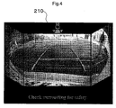
Fig. 4 ] shows an actual image in the display screen displayed by the vehicle surrounding monitor apparatus relating to the embodiment of the present invention; - [
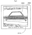
Fig. 5 ] is a view for explaining the display screen displayed by the vehicle surrounding monitor apparatus relating to the embodiment of the present invention; - [
Fig. 6 ] is a view for explaining operations of a screen generation unit relating to the embodiment of the present invention; - [
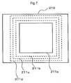
Fig. 7 ] is a view for explaining an operation at a time of screen switchover relating to the embodiment of the present invention; - [
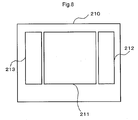
Fig. 8 ] is a schematic view showing a modified example of the display screen displayed by the vehicle surrounding monitor apparatus relating to the embodiment of the present invention; - [
Fig. 9 ] is a schematic view showing a modified example of the display screen displayed by the vehicle surrounding monitor apparatus relating to the embodiment of the present invention; - [
Fig. 10 ] is a schematic view showing a modified example of the display screen displayed by the vehicle surrounding monitor apparatus relating to the embodiment of the present invention; and - [
Fig. 11 ] is a schematic view showing a modified example of the display screen displayed by the vehicle surrounding monitor apparatus relating to the embodiment of the present invention. - Next, an embodiment of the present invention will be described with reference to the accompanying drawings.
-
Fig. 1 is a schematic view of avehicle 100 having a vehicle surroundingmonitor apparatus 50 relating to the present invention. Thevehicle 100 includes arearview camera 11 for capturing a view rearwardly of thevehicle 100. - The
rearview camera 11, as shown inFig. 1 , is mounted to a rear portion of thevehicle 100 and set to be oriented slightly downward relative to the horizontal. More particularly, the optical axis of therearview camera 11 forms an acute angle relative to the road surface on which thevehicle 100 is present. For instance, therearview camera 11 is set with a depression angle of 30 degrees approximately, and oriented toward the rear side of thevehicle 100, so that thecamera 11 can image an area extending for about 8 meters rearwardly of thevehicle 100. - Also, the
rearview camera 11 is a digital camera incorporating an capturing device such as a CCD (charge coupled device) or a CIS (CMOS image sensor) configured to output information captured by this capturing device in realtime as video information. Preferably, thisrearview camera 11 is comprised with using a wide-angle lens (having e.g. an angle of filed ranging 160 degrees or more) or a fish-eye lens. - Further, the
vehicle 100 includes anelectronic control unit 20 shown inFig. 1 . Theelectronic control unit 20 is comprised of e.g. a microcomputer having a ROM, a RAM, etc. - As will be described later, a captured image (screen image) captured by the
rearview camera 11 is transmitted to theelectronic control unit 20 to be subjected to a predetermined processing in thiselectronic control unit 20 and then displayed on a monitor 200 (displaying means) provided in the vehicle interior shown inFig. 1 and. In case a navigation system is mounted in thevehicle 100, preferably, the monitor is used also as a display device of the navigation system. - The
vehicle 100 mounts an unillustrated vehicle speed sensor for detecting the speed of thevehicle 100. Wheel-generated pulses or the vehicle speed detected by the vehicle speed sensor is transmitted to theelectronic control unit 20 through a predetermined communication means. -
Fig 2 shows a vehicle surroundingmonitor apparatus 50. A captured image captured by therearview camera 11 is transmitted to theelectronic control unit 20. Theelectronic control unit 20 includes ascreen generation unit 21 and anoutput unit 22. As will be described later, thescreen generation unit 21 generates a display screen based on the captured image captured by therearview camera 11 and inputted to thisunit 21. The generated display screen is transmitted from thescreen generation unit 21 though theoutput unit 22 to themonitor 200 to be displayed on thismonitor 200. -
Fig. 3 is a view showing adisplay screen 210 displayed on themonitor 200 of the vehicle surroundingmonitor apparatus 50 according to the present invention. For instance, if the drivers sets the shift position to the R (reverse) position, the display screen is switched to this display screen shown in thisFig. 3 . As will be described later, the captured image captured by therearview camera 11 is displayed as acenter image 211, a right-side image 212 disposed on the right side of thecenter image 211 and having an approximately parallelogram shape, and a left-side image 213 disposed on the left side of thecenter image 211 and having an approximately parallelogram shape. - Between the
center image 211 and the right-side image 212 and between thecenter image 211 and the left-side image 213, dividinglines 250 are provided for partitioning therebetween respectively. In other words, between thecenter image 211 and the right-side image 212 and between thecenter image 211 and the left-side image 213, there are provided predetermined gaps. As thecenter image 211 and the right-side image 212 are displayed with separation therebetween and thecenter image 211 and the left-side image 213 are also displayed with separation therebetween, distinction between the rear side and the lateral sides is facilitated. - Further, as shown in
Fig. 3 , the image contents of thecenter image 211 and the right-side image 212 are continuous with each other across thedividing line 250 therebetween (the continuity between their image contents is maintained). Also, thecenter image 211 and the right-side image 212 have respective adjacent sides thereof parallel with each other. The same is true with thecenter image 211 and the left-side image 213. The generation of thecenter image 211, the right-side image 212 and the left-side image 213 and the above laying-out of these images in the display screen are provided by the functions of thescreen generation unit 21. - Meanwhile, the "continuity of image contents" means presence of connection between the
center image 211 and the right-side image 212 (or the left-side image 213). More particularly, the continuity of image contents refers to such exemplary cases as agreement (or continuity) of pixel values on the mutually opposed sides of thecenter image 211 and the right-side image 212 (or the left-side image 213) when these images are laid side by side, or continuity of pixel values corresponding to a length of the predetermined gap provided between thecenter image 211 and the right-side image 212 (or the left-side image 213), albeit no agreement (or no continuity) of the pixel values on the mutually opposed sides of thecenter image 211 and the right-side image 212 (or the left-side image 213). Putting the latter case in a different way, in a situation where the pixel values on the opposed sides of thecenter image 211 and the right-side image 212 (or the left-side image 213) are in agreement (or continuity) with each other, and in case thecenter image 211 and the right-side image 212 (or the left-side image 213) are laid side by side without any gap therebetween, the border between thecenter image 211 and the right-side image 212 (or the left-side image 213) is masked with a dividing line having a predetermined width. This case is an example of the "continuity of image contents". - The
display screen 210 provided by the vehicle surroundingmonitor apparatus 50 according to the instant embodiment is configured to cause the driver to grasp the situations of the rear side and the right and left sides of the vehicle, as if the driver were viewing them in a triple mirror having right and left mirrors held to the center mirror at a predetermined angle. More particularly, in the instant embodiment, thecenter image 211 is a screen image along the forwarding direction (front face) with the steering wheel being set to an approximately straight traveling direction, and the right-side image 212 and the left-side image 213 respectively display the surrounding conditions on the right and left sides of the displayed contents of thecenter image 211. That is, the positional relationships among thecenter image 211, the right-side image 211 and the left-side image 213 correspond to the actual positional relationships, and the front side image (center image 211) is displayed in a rectangular shape and the images corresponding to the right and left sides of the front side image (the right-side image 212, the left-side image 213) are displayed in a parallelogram shape, respectively. Therefore, the wide-range rear side of thevehicle 100 can be checked for safety and also it is easy to make distinction as to which of the rear side or the lateral side an obstacle or a human is present. - Further, at an upper portion of the
display screen 210, there is displayed anicon 260 comprised of a schematic representation of thevehicle 100 and two triangles and a trapezoid. This is for causing the driver to recognize where in the surrounding of thevehicle 100 thecenter image 211, the right-side image 212 and the left-side image 213 are now displaying. - At a lower portion of the
display screen 210, there is displayed a caution-arousing text message. - The
center image 211 displays, in superposition,indicator lines 300 serving as indicators during driving by the driver. Of theseindicator lines 300, the indicator lines extending laterally in the screen indicate respective expected positions from the rear end of thevehicle 100. For instance, the indicator lines extending laterally in the screen indicate positions distant by 50 cm, 1 m and 3 m, from the rear end of thevehicle 100, respectively. - Further, of the
above indicator lines 300, the left and right two lines extending along substantially upper-lower direction of thedisplay screen 210 indicate the width of thevehicle 100 or a width resultant from addition/subtraction of a predetermined value to/from the width of thevehicle 100. - The indicator lines 300 can be either fixed lines, or lines that vary in operative association with a steering angle.
- Further, the
indicator lines 300 can be displayed in a three-dimensional manner with addition thereto of at least one of shading and side portions. This arrangement allows the driver to recognize that the vehicle is now on the road surface displayed in thecenter image 211 showing the indicator lines 300. -
Fig. 4 shows an actual screen image in the display screen displayed by the vehicle surrounding monitor apparatus relating to the embodiment of the present invention. - Next, a processing by the
screen generation unit 21 for generating the display screen will be explained. - In this
screen generation unit 21, there is first effected a distortion correction processing described in the Japanese Unexamined Patent Application Publication No.2009-12652 rearview camera 11. Referring to a case of applying the general arrangement of the distortion correction processing described in the Japanese Unexamined Patent Application Publication No.2009-12652 - In
Fig. 6 (a) , IM0 represents an image obtained after the distortion correction processing is effected on a captured image captured by therearview camera 11. - In the following discussion, it is assumed that the x coordinate has its positive side on the right side and the y coordinate has its positive side on the upper side and also that the origin 0 is the center of the captured image (capturing device).
- Next, as described below, the
center image 211, the right-side image 212 and the left-side image 213 are generated. - First, in IM0, in
Fig. 6 (b) , an area IM1 which is a rectangular area having the x coordinate: - t ≤ x ≤ t (t>0) and the y coordinate: -H/2 ≤ y ≤ H/2 (H>0) is set as thecenter image 211. In other words, as shown inFig. 6 (b) , thecenter image 211 is a partial image (IM1) having a rectangular shape with a vertical side length: H and a lateral side length: 2t. - The right-
side image 212 is generated as follows. First, as shown inFig. 6 (b) , the process specifies IM2 as an area in the IM0 wherein the x coordinate is: t≤ x ≤ t+W. Namely, IM2 is a partial image of IM0 and is adjacent IM1 within IM0. Therefore, IM2 is a rectangle having a vertical side length: H and a lateral side length: W, as shown inFig. 6 (b) . Here, through image transformation of IM2, IM2' is generated. This "image transformation" refers to setting of the pixel value: p for the coordinate values (X0, Y0) within IM2 to a pixel value for the coordinate values (X1, Y1) within IM2'. - Specifically, the process effects a coordinate transformation: X1=X0, Y1=a" (X0 - t)/W+ Y0. That is, the rectangular-shaped IM2 is image-transformed (linear transformed) into IM2' having parallelogram shape with a bottom side: H and a height: W shown in
Fig. 6 (c) . (W) represents a shearing area width, (a) represents a shearing amount, which is a predetermined value. Further, putting this image transformation in other words, this is translation of the coordinates (X0, Y0) to the coordinates (X0, Y1) (i.e. lifting up along the y axis direction). This IM2' is provided as the right-side image 212. - With the above-described image transformation, the right-
side image 212 is formed as an image which extends further upwards along the y axis direction by the shearing processing as it extends to the right side (direction of greater (x) coordinate) relative to the original image IM2 (IM0). With this, it is possible to further alleviate "collapsing" of a three-dimensional object present adjacent the right extreme end of the screen within IM2. - Similarly to the above, the left-
side image 213 is generated as follows. First, as shown inFig. 6 (b) , the process specifies IM3 as an area in the IM0 wherein the x coordinate is: t - W≤ x ≤ -t. Namely, IM3 is a partial image of IM0 and is adjacent IM1 within IM0. Therefore, IM3 is a rectangle having a vertical side length: H and a lateral side length: W, as shown inFig. 6 (b) . Here, through image transformation of IM3, IM3' is generated. This "image transformation" refers to setting of the pixel value: p for the coordinate values (X0, Y0) within IM3 to a pixel value for the coordinate values (X1, Y1) within IM3'. - Specifically, the process effects a coordinate transformation: X1=X0, Y1=ax (- X0 - t)/W+ Y0. That is, the rectangular-shaped IM3 is image-transformed (linear transformed) into IM3' having parallelogram shape with a bottom side: H and a height: W shown in
Fig. 6 (c) . This IM3' is provided as the left-side image 213. - With the above-described image transformation, the left-
side image 213 is formed as an image which extends further upwards along the y axis direction by the shearing processing as it extends to the left side (direction of smaller (x) coordinate) relative to the original image IM3 (IM0). With this, it is possible to further alleviate collapsing of a three-dimensional object present adjacent the left extreme end of the screen within IM3. - The
screen generation unit 21 lays the right-side image 212 and the left-side image 213 generated as described above on the right and left sides of thecenter image 211 respectively, thus generating thedisplay screen 210 shown inFig. 3 andFig. 4 . - Next, the mode of operation of the vehicle surrounding
monitor apparatus 50 according to the instant embodiment of the present invention will be explained. - When a driver stops the
vehicle 100 and changes the shift position from another shift position to the reversing position (R position or reversing position) to reverse it for e.g. parking, the display screen is switched over to thedisplay screen 210 shown inFig. 3 andFig. 4 . More particularly, thedisplay screen 210 shown inFig. 3 andFig. 4 is rendered into a display screen including an image ("stopped state display image") to be displayed when thevehicle 100 is under a stopped state. With this, in a situation when a reversing maneuver is about to be effected, the driver can check whether any obstacle, other traveling vehicle, a human, or the like is present in the rear surrounding of the vehicle, including, the rear lateral sides of thevehicle 100, so that the safety check for a wide area can be done appropriately. Incidentally, under this condition, if the shift position is changed from the reverse position (R position or reversing position) to another shift position, the vehicle surrounding monitor apparatus shifts into a standby mode for standing by, without effecting displaying for surrounding monitoring. In this standby mode, a navigation screen will be displayed for instance. Meanwhile, in the instant embodiment, thecenter image 211, the right-side image 212 and the left-side image 213 become the stopped state display image. - After checking the safety, when the
vehicle 100 starts reversing (traveling, movement), the vehicle surrounding monitor apparatus switches over to thedisplay screen 220 shown inFig. 5 (traveling state screen) as a display screen including an image when thevehicle 100 is not under a stopped state ("non-stopped state display image"). Therefore, in the instant embodiment, thecenter image 211 becomes the non-stopped state display image. - Therefore, the
screen generation unit 21 generates both a display screen including the stopped state display image and a further display screen including the non-stopped state display image. Incidentally, as described above, as thecenter image 211, the right-side image 212 and the left-side image 213 are the stopped state images and thecenter image 211 is the non-stopped state image, the surrounding area of thevehicle 100 displayed by the non-stopped state display image is narrower than the surrounding area of thevehicle 100 displayed by the stopped state display image. More particularly, the stopped state display image is a wide-angled display image, whereas the non-stopped state display image is a narrow-angled display image. Further, the non-stopped state display image is a partial image of the stopped state display image. - In the instant embodiment, the display screen including the non-stopped display image is the
display screen 220 shown inFig. 5 . In thisdisplay screen 220, thecenter image 211 is displayed with an enlargement by the amount corresponding to absence of displaying of the right-side image 212 and the left-side image 213. However, it is also possible to employ, as the non-stopped state display image, simply an image with the right-side image 212 and the left-side image 213 eliminated from the display screen ofFig. 3 andFig. 4 , without any enlargement of the center image 211 (i.e. thecenter image 211 only). - In the switchover from the display screen (display screen 210) including the stopped state display image to the display screen (display screen 220) including the non-stopped state display image, this may be effected as an immediate or direct switchover to the enlarged displaying of the
center image 211. In the instant embodiment, however, the above switchover is effected in a manner as follows. Firstly, from thedisplay screen 210, the right-side image 212 and the left-side image 213 are erased. then, as schematically shown inFig. 7 , theresultant center image 211 a (thecenter image 211 immediately after the erase of the right-side image 212 and the left-side image 213 therefrom) is enlarged to acenter image 211 b, afurther center image 211 c and then to a stillfurther center image 211 d. This enlargement can be done in a continuous manner or step-by-step manner. With such presentation of the process of display screen switchover to the driver, the driver can readily recognize/understand to which portion of the display screen (image) before the switchover the display screen (image) after the switchover corresponds. - Here, the start of reversing of the
vehicle 100 represents the timing when theelectronic control unit 20 determines the speed of thevehicle 100 detected by the vehicle speed sensor exceeding a predetermined speed or the vehicle having traveled by a predetermined distance from its stopped state with using an integrated numerical value of the wheel pulses from the vehicle speed sensor as the moved distance detecting means for detecting a moved distance. Alternatively, it is possible to provide both the processing for determining the speed of thevehicle 100 detected by the vehicle speed sensor having exceeded a predetermined speed and the processing for determining the vehicle having traveled by a predetermined distance from its stopped state with using an integrated numerical value of the wheel pulses from the vehicle speed sensor, such that the "start of reversing of thevehicle 100" is determined upon establishment of either one of the above conditions. Or, for more reliable determination, the "start of reversing of thevehicle 100" may be determined upon establishment of both of the above conditions. - Incidentally, if the shift position is changed from the reversing position (R position or reverse position) to another shift position while the display screen (display screen 220) including the non-stopped state display image is being displayed, the vehicle surrounding
monitor apparatus 50 will shift to the standby mode and e.g. the navigation screen will be displayed. Meanwhile, it is possible to configure such that the display screen is returned to the display screen (display screen 210) including the stopped state display image if the stopped state of the vehicle has lasted for a relatively long period (e.g. 5 seconds or 10 seconds), In this, the switchover to the display screen including the stopped state display image may be reported by means of a sound or a voice message to the driver. - With the above-described arrangement of automatically switching over to the image having an appropriate range, rather than an image having a wider viewing angle than necessary during a reversing (traveling), the driver can effect an appropriate surrounding monitoring suitable for the situation. Further, as no switch operation is required for the driver, the driver will not feel any troublesomeness.
- Further, the
vehicle 100 may sometimes not mount any illumination units for illuminating the areas of the right-side image 212 and the left-side image 213. Therefore, in the case of determination of nighttime (or in case thevehicle 100 is present at a location with low luminance such as an indoor location), advantageously, of thecenter image 211, the right-side image 212 and the left-side image 213, only the right-side image 212 and the left-side image 213 may be subject to a brightness correcting processing for displaying in greater brightness to improve the visibility. In such case, the determination of nighttime may be made based on brightness information of the entire captured image. Further alternatively, the brightness correction processing of the right-side image 212 may be made based on the brightness information of the right-side image 212 or the partial image (IM2) as the "source" image for this right-side image 212, whereas the brightness correction processing of the left-side image 213 may be made based on the brightness information of the left-side image 213 or the partial image (IM3) as the "source" image for this left-side image 213. In this case, nighttime may be determined if the brightness information is found below a predetermined threshold value, so that the right-side image 212 and the left-side image 213 may be displayed with enhanced brightness. Further alternatively, the nighttime determination may be made, based not on brightness information, but on clock-time information, or on activation of a headlight or side lamps for illumination by the driver. And, these determinations and processing are effected by theelectronic control unit 20. - Incidentally, the present embodiment may be modified as follows.
- In the foregoing embodiment, the
electronic control unit 20 is provided separately of therearview camera 11. The invention is not limited thereto. Theelectronic control unit 20 may be integrated within therearview camera 11. - In the foregoing embodiment, there was explained the case at the time of reversing of the
vehicle 100. Needless to say, the invention may be applied also to the time of forwarding of thevehicle 100. In such case, in the present embodiment, a frontview camera may be provided instead of therearview camera 11 and the determination of the shift position may be made on the forward position (D position or the like), instead of the reversing position. - In the foregoing embodiment, a captured image from the single
rearview camera 11 is divided to be displayed as thecenter image 211, the right-side image 212 and the left-side image 213. Instead, images captured by a plurality of cameras may be employed. For instance, in addition to therearview camera 11, a right-side camera for capturing the rear right-side view of thevehicle 100 and a left-side camera for capturing the rear left-side view of thevehicle 100 may also be provided, and the captured image from therearview camera 11 may be displayed in thecenter image 211, the image from the right-side camera may be displayed in the right-side image 212 and the image from the left-side camera may be displayed in the left-side image 213, respectively. That is, the arrangement is not limited to dividing an image of a single camera. In displaying images from a plurality of cameras, the positional and directional relationships between the respective images and the vehicle may be presented accurately to the driver. In such case, the capturing ranges of therearview camera 11 and the right-side camera and the left-side camera may be overlapped with each other, or may not be overlapped with each other. - In the foregoing embodiment, there was explained the case wherein the rearward surrounding of the
vehicle 100 is monitored by therearview camera 11. Needless to say, the invention may be applied also to a case wherein the forward surrounding of thevehicle 100 is monitored by a frontview camera. The invention may be applied also to a case wherein the lateral side surrounding of thevehicle 100 is monitored by side view camera. - In the foregoing embodiment, there was explained the case wherein
the right-side image 212 and the left-side image 213 each has a parallelogram shape, with the vertical side thereof not on the side of thecenter image 211 being positioned upwardly of thecenter image 211. Instead,Figs. 8-10 show modifications thereof. InFig. 8 , the right-side image 212 and the left-side image 213 each has a rectangular shape. InFig. 9 , the right-side image 212 and the left-side image 213 each has a trapezoidal shape. InFig. 10 , the right-side image 212 and the left-side image 213 each has a parallelogram shape with the vertical side thereof not on the side of thecenter image 211 being positioned downwardly of thecenter image 211. In addition to these, the right-side image 212 and the left-side image 213 each may have a triangular or polygonal shape. Also, the right-side image 212 and the left-side image 213 may be subjected to such an image modification as described above in accordance with the shape desired to be displayed in the display screen, or may not be subjected to any image modification, but formed simply as an image cut from a predetermined image in accordance with the shape desired to be displayed in the display screen. - In the foregoing embodiment, the
center image 211 has a rectangular shape. The invention is not limited thereto, but thecenter image 211 may have a hexagonal shape as shown inFig. 11 or any other polygonal shape. - Meanwhile, in all of the modifications shown in
Figs. 8-11 , the adjacent sides of thecenter image 211 and the right-side image 212 (or the left-side image 213) are parallel with each other, with a predetermined gap formed therebetween, and the image contents thereof being continuous across the predetermined gap (a dividing line). - In the foregoing embodiment, during a stopped state of the
vehicle 100, thecenter image 211, the left-side image 213 and the right-side image 212 are displayed, whereas during traveling thereof, only thecenter image 211 is displayed. Instead, during a stopped state of thevehicle 100, an image of a camera having a wide angle (e.g. 160 degrees) is displayed, whereas during traveling of the vehicle, an image having a narrow angle (e.g. about 130 degrees) which is a portion extracted from the wide angle image (partial image) may be displayed. Further, two camera, one having a wide angle, the other having a narrow angle, may be provided with displaying thereof being switched over simultaneously. Further, there may be provided images of therearview camera 11, the left-side camera for capturing the rear right side of thevehicle 100 and the left-side camera for capturing the rear left side of thevehicle 100, so that during a stopped state, the image of therearview camera 11 is displayed and also the image of at least one of the right-side camera and the left-side camera is displayed, whereas, during a traveling, only the image of therearview camera 11 is displayed. - In the foregoing embodiment, when nighttime is determined, a brightness correction processing is effected on the right-
side image 212 and the left-side image 213, to be displayed with enhanced brightness. Instead of this, an image processing such as a grayscale conversion, a reversal (a negative-positive reversal), or a grayscale conversion followed by a reversal (a negative-positive reversal), may be effected thereon. With a grayscale conversion, it becomes possible to obtain an image with as high as possible brightness even for a dark photographic subject. Also, with a reversal, a bright image can be obtained for a dark photographic subject. The sensitivity adjustment of a human eye takes place more quickly in light adaptation than in dark adaptation, so for the focus adjustment of the crystal lens too, a better response can be obtained for a light index, than for a dark index. Therefore, a negative-positive reversal of a low-brightness image is desirable in view of the human engineering, as well. Also, if a color image undergoes a negative-positive reversal, resultant colors thereof will significantly deviate from the real ones. For this reason, in case the captured image is a color image, it is desirable to effect a negative-positive reversal on a grayscale image for the purpose of alleviation of unnaturalness also. - In the foregoing embodiment, if a stopped state of the
vehicle 100 is continued for some time (e.g. 5 second, 10 seconds, etc.) after the display screen is changed to the display screen including a narrow angle image (display screen 220), the display screen is returned to the display screen including the wide angle image (stopped state display image) (display screen 210). Instead of this, once the display condition has changed to the display screen including the narrow angle image (non-stopped state display image), even if thevehicle 100 is stopped thereafter, the display screen may not be returned to the display screen including wide angle image (stopped state display image) (display screen 210). In this case, once traveling (reversing) has been started, the screen switchover is not effected after each and every vehicle stopping according to the surrounding situation. Therefore, this arrangement will be suitable for a driver who does not like frequent switchover. Incidentally, this operation, put in other words, means that once the display screen including the non-stopped state display image is displayed, the display screen including the stopped state display image will not be displayed unless the shift position of thevehicle 100 is changed to the reversing position. Here, it is possible to configure such that the operational mode of the former (the foregoing embodiment) and the operational mode of the latter (modified embodiment) may be switched over by an operation of a switch by the driver. - In the foregoing embodiment, a captured image obtained by a camera (rearview camera 11) is used without changing its viewing point (change of the viewing position, viewing direction). The invention is not limited thereto. It is also possible to use a captured image which has undergone a viewing point change. For instance, it is possible to use a viewing point changed image after a processing of increasing/decreasing the depression angle of the captured image within a range of viewing direction in which an acute angle is formed relative to the horizontal (an image displaying vehicle surrounding with a depression angle being an acute angle) or a viewing point changed image with change of the viewing position, or a viewing point changed image after combination of such processings.
- The present invention is applicable to a vehicle surrounding monitor apparatus configured to effect a predetermined processing on a captured image of the surrounding of a vehicle captured by a camera and to display the resultant image on a display device provided in the vehicle interior.
-
- 11:
- rearview camera (capturing means)
- 20:
- electronic control unit
- 21:
- screen generation unit (screen generating means)
- 50:
- vehicle surrounding monitor apparatus
- 100:
- vehicle
- 200:
- monitor (displaying means)
- 210:
- display screen
- 220:
- display screen
- 211:
- center image (first image)
- 212:
- right-side image (second image)
- 213:
- left-side image (third image)
- 250:
- dividing line
- 260:
- icon
- 300:
- indicator line
Claims (18)
- A vehicle surrounding monitor apparatus comprising:at least one image capturing means for capturing an image of the surrounding of a vehicle;a screen generating means for generating a first image and a second image having image contents continuous with image contents of said first image, based on a captured image imaged by said capturing means, and generating also a display screen comprised of the first image and the second image laid side by side with a predetermined gap therebetween; anda displaying means for displaying the display screen generated by said screen generating means.
- The vehicle surrounding monitor apparatus according to claim 1, wherein said first image and said second image are images displaying the vehicle surrounding from a viewing point at an acute angle relative to the horizontal direction.
- The vehicle surrounding monitor apparatus according to claim 1 or 2, wherein said screen generating means generates said second image continuous in the left direction from said first image and said further second image continuous in the right direction from said first image and generates a display screen with said two second images laid on the right and left sides of said first image.
- The vehicle surrounding monitor apparatus according to any one of claims 1-3, wherein said first image has a rectangular shape and said second image has a non-rectangular, parallelogram shape; and in said display screen, said first image and said second image have adjacent sides thereof disposed parallel with each other.
- The vehicle surrounding monitor apparatus according to claim 4, wherein said screen generating means generates said second image by image-modifying at least a portion of the captured image into said parallelogram shape.
- A vehicle surrounding monitor apparatus comprising:at least one image capturing means for capturing an image of the surrounding of a vehicle;a screen generating means for generating a first image and a second image having a non-rectangular, parallelogram shape and image contents continuous with image contents of said first image, based on a captured image imaged by said capturing means, and generating also a display screen comprised of the first image and the second image laid side by side; anda displaying means for displaying the display screen generated by said screen generating means.
- The vehicle surrounding monitor apparatus according to claim 6, wherein said first image and said second image are images displaying the vehicle surrounding from a viewing point at an acute angle relative to the horizontal direction.
- The vehicle surrounding monitor apparatus according to claim 6 or 7, wherein said screen generating means generates said second image continuous in the left direction from said first image and said further second image continuous in the right direction from said first image and generates a display screen with said two second images laid on the right and left sides of said first image.
- The vehicle surrounding monitor apparatus according to any one of claims 6-8, wherein said first image has a rectangular shape; and in said display screen, said first image and said second image have adjacent sides thereof disposed parallel with each other.
- The vehicle surrounding monitor apparatus according to any one of claims 6-8, wherein said screen generating means generates said second image by image-modifying at least a portion of the captured image into said parallelogram shape.
- A vehicle surrounding monitor apparatus comprising:at least one image capturing means for capturing an image of the surrounding of a vehicle;a screen generating means for generating a first image and a second image having image contents continuous with image contents of said first image, based on a captured image imaged by said capturing means, and generating also a display screen comprised of the first image and the second image laid side by side; anda displaying means for displaying the display screen generated by said screen generating means;wherein said second image is generated by image-modifying at least a portion of the captured image such that the greater the lateral distance from the side of the first image in said display screen, the greater an amount of upper modification.
- The vehicle surrounding monitor apparatus according to claim 11, wherein said first image and said second image are images displaying the vehicle surrounding from a viewing point at an acute angle relative to the horizontal direction.
- The vehicle surrounding monitor apparatus according to claim 11 or 12, wherein said screen generating means generates said second image continuous in the left direction from said first image and said further second image continuous in the right direction from said first image and generates a display screen with said two second images laid on the right and left sides of said first image.
- The vehicle surrounding monitor apparatus according to any one of claims 11-13, wherein said screen generating means generates the display screen comprised of the first image and the second image laid side by side with a predetermined gap therebetween.
- The vehicle surrounding monitor apparatus according to any one of claims 11-14, wherein said first image has a rectangular shape and said second image has a non-rectangular, parallelogram shape; and in said display screen, said first image and said second image have adjacent sides thereof disposed parallel with each other.
- The vehicle surrounding monitor apparatus according to any one of claims 1-15, wherein said screen generating means enhances the brightness of said second image when a nighttime is determined.
- The vehicle surrounding monitor apparatus according to any one of claims 1-15, wherein said screen generating means effects a grayscale conversion on said second image when a nighttime is determined.
- The vehicle surrounding monitor apparatus according to any one of claims 1-15, wherein said screen generating means effects a negative-positive reversal on said second image when a nighttime is determined.
Applications Claiming Priority (2)
| Application Number | Priority Date | Filing Date | Title |
|---|---|---|---|
| JP2009210052 | 2009-09-11 | ||
| PCT/JP2010/064864 WO2011030698A1 (en) | 2009-09-11 | 2010-09-01 | Device for monitoring surroundings of vehicle |
Publications (3)
| Publication Number | Publication Date |
|---|---|
| EP2476587A1 true EP2476587A1 (en) | 2012-07-18 |
| EP2476587A4 EP2476587A4 (en) | 2014-09-24 |
| EP2476587B1 EP2476587B1 (en) | 2018-04-25 |
Family
ID=43732371
Family Applications (1)
| Application Number | Title | Priority Date | Filing Date |
|---|---|---|---|
| EP10815295.0A Not-in-force EP2476587B1 (en) | 2009-09-11 | 2010-09-01 | Vehicle surrounding monitor apparatus |
Country Status (5)
| Country | Link |
|---|---|
| US (1) | US20120154589A1 (en) |
| EP (1) | EP2476587B1 (en) |
| JP (1) | JP5598731B2 (en) |
| CN (1) | CN102481875A (en) |
| WO (1) | WO2011030698A1 (en) |
Cited By (4)
| Publication number | Priority date | Publication date | Assignee | Title |
|---|---|---|---|---|
| EP2551817A3 (en) * | 2011-07-28 | 2013-12-18 | Robert Bosch Gmbh | Vehicle rear view camera system and method |
| WO2014033099A3 (en) * | 2012-08-27 | 2014-04-24 | Digital Optics Corporation Europe Limited | Rearview imaging systems for vehicle |
| WO2019135099A1 (en) * | 2018-01-05 | 2019-07-11 | Volvo Truck Corporation | Camera monitoring system with a display displaying an undistorted portion of a wide angle image adjoining at least one distorted portion of the wide angle image |
| WO2019180001A1 (en) * | 2018-03-22 | 2019-09-26 | Renault S.A.S | Panoramic vision system the view of which is displayed on a portrait screen |
Families Citing this family (10)
| Publication number | Priority date | Publication date | Assignee | Title |
|---|---|---|---|---|
| DE102011121616A1 (en) * | 2011-12-20 | 2013-06-20 | Audi Ag | Method for controlling a display device of a motor vehicle |
| DE102012200731A1 (en) | 2012-01-19 | 2013-07-25 | Robert Bosch Gmbh | Method and device for visualizing the environment of a vehicle |
| US10493916B2 (en) * | 2012-02-22 | 2019-12-03 | Magna Electronics Inc. | Vehicle camera system with image manipulation |
| DE102014201161A1 (en) * | 2014-01-23 | 2015-07-23 | Robert Bosch Gmbh | Method and device for determining a blind area of a camera |
| DE102015216907A1 (en) * | 2015-09-03 | 2017-03-09 | Robert Bosch Gmbh | Digital rearview mirror |
| JP6766715B2 (en) * | 2017-03-22 | 2020-10-14 | トヨタ自動車株式会社 | Display control device for vehicles |
| CN108725319B (en) * | 2017-10-31 | 2021-05-04 | 无锡职业技术学院 | Image type car backing guidance method |
| CN110949255A (en) * | 2019-12-23 | 2020-04-03 | 深圳市豪恩汽车电子装备股份有限公司 | Auxiliary parking device and method for motor vehicle |
| CN110949257A (en) * | 2019-12-23 | 2020-04-03 | 深圳市豪恩汽车电子装备股份有限公司 | Auxiliary parking device and method for motor vehicle |
| CN110949256A (en) * | 2019-12-23 | 2020-04-03 | 深圳市豪恩汽车电子装备股份有限公司 | Auxiliary parking device and method for motor vehicle |
Citations (2)
| Publication number | Priority date | Publication date | Assignee | Title |
|---|---|---|---|---|
| EP1288618A2 (en) * | 2001-08-09 | 2003-03-05 | Matsushita Electric Industrial Co., Ltd. | Driving assistance display apparatus |
| US20050012685A1 (en) * | 2002-03-05 | 2005-01-20 | Tsuyoshi Okada | Image display controller |
Family Cites Families (14)
| Publication number | Priority date | Publication date | Assignee | Title |
|---|---|---|---|---|
| JPH11243538A (en) * | 1998-02-25 | 1999-09-07 | Nissan Motor Co Ltd | Visually recognizing device for vehicle |
| US6587130B1 (en) * | 1998-11-09 | 2003-07-01 | Yazaki Corporation | Multi-function switch device |
| CN2424965Y (en) * | 2000-03-01 | 2001-03-28 | 张士杰 | Safety monitoring device for backing car |
| JP3866109B2 (en) * | 2002-01-16 | 2007-01-10 | 富士通テン株式会社 | In-vehicle imaging device |
| JP2005184523A (en) * | 2003-12-19 | 2005-07-07 | Matsushita Electric Ind Co Ltd | On-vehicle monitoring camera apparatus |
| JP4730883B2 (en) * | 2004-11-09 | 2011-07-20 | 日本輸送機株式会社 | Lifting carriage |
| JP2006137383A (en) * | 2004-11-15 | 2006-06-01 | Niles Co Ltd | Photographing device for vehicle |
| JP2006168699A (en) * | 2004-11-22 | 2006-06-29 | Nagano Kogaku Kenkyusho:Kk | Display method of monitoring image of vehicle |
| JP2006285573A (en) * | 2005-03-31 | 2006-10-19 | Fuji Photo Film Co Ltd | Image processing method, program, and image processing system |
| JP2007013035A (en) * | 2005-07-04 | 2007-01-18 | Fujifilm Holdings Corp | Drawing apparatus, drawing method, and program for drawing |
| JP2007142624A (en) * | 2005-11-16 | 2007-06-07 | Matsushita Electric Ind Co Ltd | Vehicle mounted imaging apparatus |
| US8194132B2 (en) * | 2006-01-20 | 2012-06-05 | Old World Industries, Llc | System for monitoring an area adjacent a vehicle |
| JP4924896B2 (en) | 2007-07-05 | 2012-04-25 | アイシン精機株式会社 | Vehicle periphery monitoring device |
| WO2009104675A1 (en) * | 2008-02-20 | 2009-08-27 | クラリオン株式会社 | Vehicle peripheral image display system |
-
2010
- 2010-09-01 JP JP2011530810A patent/JP5598731B2/en not_active Expired - Fee Related
- 2010-09-01 WO PCT/JP2010/064864 patent/WO2011030698A1/en active Application Filing
- 2010-09-01 EP EP10815295.0A patent/EP2476587B1/en not_active Not-in-force
- 2010-09-01 CN CN2010800388642A patent/CN102481875A/en active Pending
- 2010-09-01 US US13/390,737 patent/US20120154589A1/en not_active Abandoned
Patent Citations (2)
| Publication number | Priority date | Publication date | Assignee | Title |
|---|---|---|---|---|
| EP1288618A2 (en) * | 2001-08-09 | 2003-03-05 | Matsushita Electric Industrial Co., Ltd. | Driving assistance display apparatus |
| US20050012685A1 (en) * | 2002-03-05 | 2005-01-20 | Tsuyoshi Okada | Image display controller |
Non-Patent Citations (1)
| Title |
|---|
| See also references of WO2011030698A1 * |
Cited By (7)
| Publication number | Priority date | Publication date | Assignee | Title |
|---|---|---|---|---|
| EP2551817A3 (en) * | 2011-07-28 | 2013-12-18 | Robert Bosch Gmbh | Vehicle rear view camera system and method |
| WO2014033099A3 (en) * | 2012-08-27 | 2014-04-24 | Digital Optics Corporation Europe Limited | Rearview imaging systems for vehicle |
| US9242602B2 (en) | 2012-08-27 | 2016-01-26 | Fotonation Limited | Rearview imaging systems for vehicle |
| WO2019135099A1 (en) * | 2018-01-05 | 2019-07-11 | Volvo Truck Corporation | Camera monitoring system with a display displaying an undistorted portion of a wide angle image adjoining at least one distorted portion of the wide angle image |
| US11613207B2 (en) | 2018-01-05 | 2023-03-28 | Volvo Truck Corporation | Camera monitoring system with a display displaying an undistorted portion of a wide angle image adjoining at least one distorted portion of the wide angle image |
| WO2019180001A1 (en) * | 2018-03-22 | 2019-09-26 | Renault S.A.S | Panoramic vision system the view of which is displayed on a portrait screen |
| FR3079180A1 (en) * | 2018-03-22 | 2019-09-27 | Renault S.A.S. | PANORAMIC VISION SYSTEM DISPLAYED ON A PORTRAIT SCREEN |
Also Published As
| Publication number | Publication date |
|---|---|
| EP2476587B1 (en) | 2018-04-25 |
| CN102481875A (en) | 2012-05-30 |
| WO2011030698A1 (en) | 2011-03-17 |
| US20120154589A1 (en) | 2012-06-21 |
| JPWO2011030698A1 (en) | 2013-02-07 |
| EP2476587A4 (en) | 2014-09-24 |
| JP5598731B2 (en) | 2014-10-01 |
Similar Documents
| Publication | Publication Date | Title |
|---|---|---|
| EP2476587B1 (en) | Vehicle surrounding monitor apparatus | |
| EP2476588B1 (en) | Vehicle surrounding monitor apparatus | |
| US11052823B2 (en) | Vehicle rear monitoring system | |
| JP7160301B2 (en) | MONITOR DISPLAY SYSTEM AND ITS DISPLAY METHOD | |
| JP4766841B2 (en) | Camera device and vehicle periphery monitoring device mounted on vehicle | |
| JP4254887B2 (en) | Image display system for vehicles | |
| US10029621B2 (en) | Rear view camera system using rear view mirror location | |
| JP3511892B2 (en) | Ambient monitoring device for vehicles | |
| US20020075387A1 (en) | Arrangement and process for monitoring the surrounding area of an automobile | |
| CN110509851B (en) | Multi-curvature electronic rearview mirror with follow-up display | |
| JP2005110202A (en) | Camera apparatus and apparatus for monitoring vehicle periphery | |
| JP2008001182A (en) | Vehicular visual information presenting device and method | |
| JP5724446B2 (en) | Vehicle driving support device | |
| JP2011253448A (en) | Vehicle periphery monitoring device | |
| JP2011193485A (en) | Camera device mounted on vehicle, and apparatus for monitoring vehicle periphery | |
| US20180301122A1 (en) | Display control apparatus, display control method, and camera monitoring system | |
| KR101657673B1 (en) | Apparatus and method for generating panorama view | |
| US10594934B2 (en) | Vehicle display | |
| JP2008285105A (en) | Information display device | |
| JP2007290570A (en) | Vehicular display device | |
| KR20110087085A (en) | Car side mirror system having a camera video display function | |
| KR20170064134A (en) | Displaying control apparatus of head up display and method thereof | |
| JP2014021543A (en) | Visual field support device and program for vehicle | |
| JP4033170B2 (en) | Vehicle display device | |
| CN211893039U (en) | Vehicle adopting multi-curvature electronic rearview mirror system |
Legal Events
| Date | Code | Title | Description |
|---|---|---|---|
| PUAI | Public reference made under article 153(3) epc to a published international application that has entered the european phase |
Free format text: ORIGINAL CODE: 0009012 |
|
| 17P | Request for examination filed |
Effective date: 20120208 |
|
| AK | Designated contracting states |
Kind code of ref document: A1 Designated state(s): AL AT BE BG CH CY CZ DE DK EE ES FI FR GB GR HR HU IE IS IT LI LT LU LV MC MK MT NL NO PL PT RO SE SI SK SM TR |
|
| DAX | Request for extension of the european patent (deleted) | ||
| A4 | Supplementary search report drawn up and despatched |
Effective date: 20140822 |
|
| RIC1 | Information provided on ipc code assigned before grant |
Ipc: B60R 11/02 20060101ALI20140818BHEP Ipc: G06T 15/10 20110101ALI20140818BHEP Ipc: H04N 7/18 20060101ALI20140818BHEP Ipc: B60R 1/00 20060101AFI20140818BHEP |
|
| GRAP | Despatch of communication of intention to grant a patent |
Free format text: ORIGINAL CODE: EPIDOSNIGR1 |
|
| INTG | Intention to grant announced |
Effective date: 20171113 |
|
| GRAA | (expected) grant |
Free format text: ORIGINAL CODE: 0009210 |
|
| GRAS | Grant fee paid |
Free format text: ORIGINAL CODE: EPIDOSNIGR3 |
|
| AK | Designated contracting states |
Kind code of ref document: B1 Designated state(s): AL AT BE BG CH CY CZ DE DK EE ES FI FR GB GR HR HU IE IS IT LI LT LU LV MC MK MT NL NO PL PT RO SE SI SK SM TR |
|
| REG | Reference to a national code |
Ref country code: GB Ref legal event code: FG4D |
|
| REG | Reference to a national code |
Ref country code: CH Ref legal event code: EP |
|
| REG | Reference to a national code |
Ref country code: AT Ref legal event code: REF Ref document number: 992506 Country of ref document: AT Kind code of ref document: T Effective date: 20180515 |
|
| REG | Reference to a national code |
Ref country code: IE Ref legal event code: FG4D |
|
| REG | Reference to a national code |
Ref country code: DE Ref legal event code: R096 Ref document number: 602010050251 Country of ref document: DE |
|
| REG | Reference to a national code |
Ref country code: FR Ref legal event code: PLFP Year of fee payment: 9 |
|
| REG | Reference to a national code |
Ref country code: NL Ref legal event code: MP Effective date: 20180425 |
|
| REG | Reference to a national code |
Ref country code: LT Ref legal event code: MG4D |
|
| PG25 | Lapsed in a contracting state [announced via postgrant information from national office to epo] |
Ref country code: NL Free format text: LAPSE BECAUSE OF FAILURE TO SUBMIT A TRANSLATION OF THE DESCRIPTION OR TO PAY THE FEE WITHIN THE PRESCRIBED TIME-LIMIT Effective date: 20180425 |
|
| PG25 | Lapsed in a contracting state [announced via postgrant information from national office to epo] |
Ref country code: NO Free format text: LAPSE BECAUSE OF FAILURE TO SUBMIT A TRANSLATION OF THE DESCRIPTION OR TO PAY THE FEE WITHIN THE PRESCRIBED TIME-LIMIT Effective date: 20180725 Ref country code: LT Free format text: LAPSE BECAUSE OF FAILURE TO SUBMIT A TRANSLATION OF THE DESCRIPTION OR TO PAY THE FEE WITHIN THE PRESCRIBED TIME-LIMIT Effective date: 20180425 Ref country code: BG Free format text: LAPSE BECAUSE OF FAILURE TO SUBMIT A TRANSLATION OF THE DESCRIPTION OR TO PAY THE FEE WITHIN THE PRESCRIBED TIME-LIMIT Effective date: 20180725 Ref country code: FI Free format text: LAPSE BECAUSE OF FAILURE TO SUBMIT A TRANSLATION OF THE DESCRIPTION OR TO PAY THE FEE WITHIN THE PRESCRIBED TIME-LIMIT Effective date: 20180425 Ref country code: SE Free format text: LAPSE BECAUSE OF FAILURE TO SUBMIT A TRANSLATION OF THE DESCRIPTION OR TO PAY THE FEE WITHIN THE PRESCRIBED TIME-LIMIT Effective date: 20180425 Ref country code: PL Free format text: LAPSE BECAUSE OF FAILURE TO SUBMIT A TRANSLATION OF THE DESCRIPTION OR TO PAY THE FEE WITHIN THE PRESCRIBED TIME-LIMIT Effective date: 20180425 Ref country code: ES Free format text: LAPSE BECAUSE OF FAILURE TO SUBMIT A TRANSLATION OF THE DESCRIPTION OR TO PAY THE FEE WITHIN THE PRESCRIBED TIME-LIMIT Effective date: 20180425 |
|
| PG25 | Lapsed in a contracting state [announced via postgrant information from national office to epo] |
Ref country code: GR Free format text: LAPSE BECAUSE OF FAILURE TO SUBMIT A TRANSLATION OF THE DESCRIPTION OR TO PAY THE FEE WITHIN THE PRESCRIBED TIME-LIMIT Effective date: 20180726 Ref country code: HR Free format text: LAPSE BECAUSE OF FAILURE TO SUBMIT A TRANSLATION OF THE DESCRIPTION OR TO PAY THE FEE WITHIN THE PRESCRIBED TIME-LIMIT Effective date: 20180425 Ref country code: LV Free format text: LAPSE BECAUSE OF FAILURE TO SUBMIT A TRANSLATION OF THE DESCRIPTION OR TO PAY THE FEE WITHIN THE PRESCRIBED TIME-LIMIT Effective date: 20180425 |
|
| REG | Reference to a national code |
Ref country code: AT Ref legal event code: MK05 Ref document number: 992506 Country of ref document: AT Kind code of ref document: T Effective date: 20180425 |
|
| PG25 | Lapsed in a contracting state [announced via postgrant information from national office to epo] |
Ref country code: PT Free format text: LAPSE BECAUSE OF FAILURE TO SUBMIT A TRANSLATION OF THE DESCRIPTION OR TO PAY THE FEE WITHIN THE PRESCRIBED TIME-LIMIT Effective date: 20180827 |
|
| REG | Reference to a national code |
Ref country code: DE Ref legal event code: R097 Ref document number: 602010050251 Country of ref document: DE |
|
| PG25 | Lapsed in a contracting state [announced via postgrant information from national office to epo] |
Ref country code: DK Free format text: LAPSE BECAUSE OF FAILURE TO SUBMIT A TRANSLATION OF THE DESCRIPTION OR TO PAY THE FEE WITHIN THE PRESCRIBED TIME-LIMIT Effective date: 20180425 Ref country code: AT Free format text: LAPSE BECAUSE OF FAILURE TO SUBMIT A TRANSLATION OF THE DESCRIPTION OR TO PAY THE FEE WITHIN THE PRESCRIBED TIME-LIMIT Effective date: 20180425 Ref country code: EE Free format text: LAPSE BECAUSE OF FAILURE TO SUBMIT A TRANSLATION OF THE DESCRIPTION OR TO PAY THE FEE WITHIN THE PRESCRIBED TIME-LIMIT Effective date: 20180425 Ref country code: CZ Free format text: LAPSE BECAUSE OF FAILURE TO SUBMIT A TRANSLATION OF THE DESCRIPTION OR TO PAY THE FEE WITHIN THE PRESCRIBED TIME-LIMIT Effective date: 20180425 Ref country code: RO Free format text: LAPSE BECAUSE OF FAILURE TO SUBMIT A TRANSLATION OF THE DESCRIPTION OR TO PAY THE FEE WITHIN THE PRESCRIBED TIME-LIMIT Effective date: 20180425 Ref country code: SK Free format text: LAPSE BECAUSE OF FAILURE TO SUBMIT A TRANSLATION OF THE DESCRIPTION OR TO PAY THE FEE WITHIN THE PRESCRIBED TIME-LIMIT Effective date: 20180425 |
|
| PG25 | Lapsed in a contracting state [announced via postgrant information from national office to epo] |
Ref country code: SM Free format text: LAPSE BECAUSE OF FAILURE TO SUBMIT A TRANSLATION OF THE DESCRIPTION OR TO PAY THE FEE WITHIN THE PRESCRIBED TIME-LIMIT Effective date: 20180425 Ref country code: IT Free format text: LAPSE BECAUSE OF FAILURE TO SUBMIT A TRANSLATION OF THE DESCRIPTION OR TO PAY THE FEE WITHIN THE PRESCRIBED TIME-LIMIT Effective date: 20180425 |
|
| PLBE | No opposition filed within time limit |
Free format text: ORIGINAL CODE: 0009261 |
|
| STAA | Information on the status of an ep patent application or granted ep patent |
Free format text: STATUS: NO OPPOSITION FILED WITHIN TIME LIMIT |
|
| 26N | No opposition filed |
Effective date: 20190128 |
|
| PG25 | Lapsed in a contracting state [announced via postgrant information from national office to epo] |
Ref country code: MC Free format text: LAPSE BECAUSE OF FAILURE TO SUBMIT A TRANSLATION OF THE DESCRIPTION OR TO PAY THE FEE WITHIN THE PRESCRIBED TIME-LIMIT Effective date: 20180425 |
|
| REG | Reference to a national code |
Ref country code: CH Ref legal event code: PL |
|
| GBPC | Gb: european patent ceased through non-payment of renewal fee |
Effective date: 20180901 |
|
| PG25 | Lapsed in a contracting state [announced via postgrant information from national office to epo] |
Ref country code: SI Free format text: LAPSE BECAUSE OF FAILURE TO SUBMIT A TRANSLATION OF THE DESCRIPTION OR TO PAY THE FEE WITHIN THE PRESCRIBED TIME-LIMIT Effective date: 20180425 |
|
| REG | Reference to a national code |
Ref country code: BE Ref legal event code: MM Effective date: 20180930 |
|
| REG | Reference to a national code |
Ref country code: IE Ref legal event code: MM4A |
|
| PG25 | Lapsed in a contracting state [announced via postgrant information from national office to epo] |
Ref country code: LU Free format text: LAPSE BECAUSE OF NON-PAYMENT OF DUE FEES Effective date: 20180901 |
|
| PG25 | Lapsed in a contracting state [announced via postgrant information from national office to epo] |
Ref country code: IE Free format text: LAPSE BECAUSE OF NON-PAYMENT OF DUE FEES Effective date: 20180901 |
|
| PG25 | Lapsed in a contracting state [announced via postgrant information from national office to epo] |
Ref country code: LI Free format text: LAPSE BECAUSE OF NON-PAYMENT OF DUE FEES Effective date: 20180930 Ref country code: BE Free format text: LAPSE BECAUSE OF NON-PAYMENT OF DUE FEES Effective date: 20180930 Ref country code: CH Free format text: LAPSE BECAUSE OF NON-PAYMENT OF DUE FEES Effective date: 20180930 |
|
| PG25 | Lapsed in a contracting state [announced via postgrant information from national office to epo] |
Ref country code: GB Free format text: LAPSE BECAUSE OF NON-PAYMENT OF DUE FEES Effective date: 20180901 |
|
| PGFP | Annual fee paid to national office [announced via postgrant information from national office to epo] |
Ref country code: DE Payment date: 20190820 Year of fee payment: 10 |
|
| PG25 | Lapsed in a contracting state [announced via postgrant information from national office to epo] |
Ref country code: AL Free format text: LAPSE BECAUSE OF FAILURE TO SUBMIT A TRANSLATION OF THE DESCRIPTION OR TO PAY THE FEE WITHIN THE PRESCRIBED TIME-LIMIT Effective date: 20180425 |
|
| PG25 | Lapsed in a contracting state [announced via postgrant information from national office to epo] |
Ref country code: MT Free format text: LAPSE BECAUSE OF NON-PAYMENT OF DUE FEES Effective date: 20180901 |
|
| PG25 | Lapsed in a contracting state [announced via postgrant information from national office to epo] |
Ref country code: TR Free format text: LAPSE BECAUSE OF FAILURE TO SUBMIT A TRANSLATION OF THE DESCRIPTION OR TO PAY THE FEE WITHIN THE PRESCRIBED TIME-LIMIT Effective date: 20180425 |
|
| PG25 | Lapsed in a contracting state [announced via postgrant information from national office to epo] |
Ref country code: HU Free format text: LAPSE BECAUSE OF FAILURE TO SUBMIT A TRANSLATION OF THE DESCRIPTION OR TO PAY THE FEE WITHIN THE PRESCRIBED TIME-LIMIT; INVALID AB INITIO Effective date: 20100901 |
|
| PG25 | Lapsed in a contracting state [announced via postgrant information from national office to epo] |
Ref country code: MK Free format text: LAPSE BECAUSE OF NON-PAYMENT OF DUE FEES Effective date: 20180425 Ref country code: CY Free format text: LAPSE BECAUSE OF FAILURE TO SUBMIT A TRANSLATION OF THE DESCRIPTION OR TO PAY THE FEE WITHIN THE PRESCRIBED TIME-LIMIT Effective date: 20180425 |
|
| PG25 | Lapsed in a contracting state [announced via postgrant information from national office to epo] |
Ref country code: IS Free format text: LAPSE BECAUSE OF FAILURE TO SUBMIT A TRANSLATION OF THE DESCRIPTION OR TO PAY THE FEE WITHIN THE PRESCRIBED TIME-LIMIT Effective date: 20180825 |
|
| PGFP | Annual fee paid to national office [announced via postgrant information from national office to epo] |
Ref country code: FR Payment date: 20200715 Year of fee payment: 11 |
|
| REG | Reference to a national code |
Ref country code: DE Ref legal event code: R119 Ref document number: 602010050251 Country of ref document: DE |
|
| PG25 | Lapsed in a contracting state [announced via postgrant information from national office to epo] |
Ref country code: DE Free format text: LAPSE BECAUSE OF NON-PAYMENT OF DUE FEES Effective date: 20210401 |
|
| PG25 | Lapsed in a contracting state [announced via postgrant information from national office to epo] |
Ref country code: FR Free format text: LAPSE BECAUSE OF NON-PAYMENT OF DUE FEES Effective date: 20210930 |