EP2476586A1 - Method for producing sounds for turn signal sounds for an automobile and sounder for turn signal sounds for an automobile - Google Patents
Method for producing sounds for turn signal sounds for an automobile and sounder for turn signal sounds for an automobile Download PDFInfo
- Publication number
- EP2476586A1 EP2476586A1 EP10813637A EP10813637A EP2476586A1 EP 2476586 A1 EP2476586 A1 EP 2476586A1 EP 10813637 A EP10813637 A EP 10813637A EP 10813637 A EP10813637 A EP 10813637A EP 2476586 A1 EP2476586 A1 EP 2476586A1
- Authority
- EP
- European Patent Office
- Prior art keywords
- signal
- sound
- turn
- pulse
- frequency
- Prior art date
- Legal status (The legal status is an assumption and is not a legal conclusion. Google has not performed a legal analysis and makes no representation as to the accuracy of the status listed.)
- Granted
Links
Images


Classifications
-
- B—PERFORMING OPERATIONS; TRANSPORTING
- B60—VEHICLES IN GENERAL
- B60Q—ARRANGEMENT OF SIGNALLING OR LIGHTING DEVICES, THE MOUNTING OR SUPPORTING THEREOF OR CIRCUITS THEREFOR, FOR VEHICLES IN GENERAL
- B60Q5/00—Arrangement or adaptation of acoustic signal devices
- B60Q5/005—Arrangement or adaptation of acoustic signal devices automatically actuated
-
- B—PERFORMING OPERATIONS; TRANSPORTING
- B60—VEHICLES IN GENERAL
- B60Q—ARRANGEMENT OF SIGNALLING OR LIGHTING DEVICES, THE MOUNTING OR SUPPORTING THEREOF OR CIRCUITS THEREFOR, FOR VEHICLES IN GENERAL
- B60Q1/00—Arrangement of optical signalling or lighting devices, the mounting or supporting thereof or circuits therefor
- B60Q1/26—Arrangement of optical signalling or lighting devices, the mounting or supporting thereof or circuits therefor the devices being primarily intended to indicate the vehicle, or parts thereof, or to give signals, to other traffic
- B60Q1/34—Arrangement of optical signalling or lighting devices, the mounting or supporting thereof or circuits therefor the devices being primarily intended to indicate the vehicle, or parts thereof, or to give signals, to other traffic for indicating change of drive direction
Definitions
- the present invention relates to a method for generating turn-signal sound of a vehicle and a device for generating turn-signal sound of a vehicle.
- turn-signal sound of a vehicle utilized an operating sound generated by an activated mechanical relay for flashing a turn-signal lamp.
- a semiconductor switch for the turn-signal lamp instead of the mechanical relay.
- the turn-signal sound cannot be generated from the semiconductor switch and thus there is a proposal of generating the turn-signal sound by outputting a pulse signal from a sound generator port (hereinafter called an S/G port) of a central processing unit (CPU), converting the pulse signal into an analog signal using an integration circuit, and providing the analog signal to a speaker or a piezoelectric buzzer or the like which is intermittently activated to produce the turn-signal sound.
- a sound generator port hereinafter called an S/G port
- CPU central processing unit
- the above-described CPU is also used to generate an alarm sound from the above-described speaker and the piezoelectric buzzer when an alarm is activated, by outputting the pulse signal to the above-described speaker and the piezoelectric buzzer.
- the respective sounds are arranged according to a priority order so that when an event occurs which requires generating the sound with a higher priority order while generating the sound with a lower priority order, the sound with the lower priority order is cancelled in order to generate the sound with the higher priority order.
- both of the turn-signal sound and the alarm sound can be produced using the single device, however, the sound with the lower priority order is cancelled when producing both sounds at the same time. As a result, the user may feel uncomfortable.
- an object of the present invention is to provide a method for generating turn-signal sound of a vehicle which can satisfy the user's demand for the tone of the turn-signal sound at low cost.
- Another object of the present invention is to provide a device for generating turn-signal sound of a vehicle.
- the present invention provides, in a first aspect, a method for generating turn-signal sound of a vehicle, including the steps of: outputting a pulse signal for turn-signal sound from a pulse pattern generator, the pulse signal for turn-signal sound having varying frequency and duty ratio; converting the pulse signal for turn-signal sound into an analog signal for turn-signal sound by integrating the pulse signal for turn-signal sound; and outputting the analog signal for turn-signal sound to a speaker.
- the present invention provides, in a second aspect, the method as described above, further including the steps of: outputting a pulse signal for alarm sound from a sound generator, the pulse signal for alarm sound having the constant frequency and the constant duty ratio; converting the pulse signal for alarm sound into an analog signal for alarm sound by integrating the pulse signal for alarm sound; summing up the analog signal for turn-signal sound and the analog signal for alarm sound; and outputting the summed signal instead of the analog signal for turn-signal sound to the speaker.
- the present invention provides, in a third aspect, the method as described above, wherein the pulse signal for turn-signal sound outputted from the pulse pattern generator has the frequency and the duty ratio arranged to vary according to the frequency and the sound pressure corresponding to the frequency included in an operating sound of a mechanical relay.
- the present invention provides, in a fourth aspect, a device for generating turn-signal sound of a vehicle, including: a central processing unit for outputting from a pulse pattern generator a pulse signal for turn-signal sound having varying frequency and duty ratio; an integration unit for integrating the pulse signal for turn-signal sound to convert the pulse signal for turn-signal sound into an analog signal for turn-signal sound; and a speaker to which the analog signal for turn-signal sound is outputted.
- the pulse signal for turn-signal sound is integrated and outputted to the speaker.
- the frequency of the sound outputted from the speaker can be determined according to the pulse signal for turn-signal sound
- the sound-volume of the sound outputted from the speaker can be determined according to the duty ratio of the pulse signal for turn-signal sound.
- the speaker can output the sound having the varying frequency and sound-volume.
- the tone of the turn-signal sound outputted from the speaker can be adjusted by adjusting the frequency and the duty ratio of the pulse signal for turn-signal sound, thereby satisfying the user's particular demand regarding to the tone of the turn-signal sound. Furthermore, since the pulse signal for turn-signal sound is integrated and outputted to the speaker, a D/A converter for decoding is not required, thus the cost can be reduced. Therefore, the user's demand for the tone of the turn-signal sound can be satisfied without increasing the cost.
- the analog signal for turn-signal sound and the analog signal for alarm sound are summed up and the summed signal is outputted to the speaker.
- the turn-signal sound and the alarm sound can be outputted simultaneously from a single speaker.
- the frequency and the duty ratio of the pulse signal for turn-signal sound are varying according to the frequency and the sound pressure corresponding to the frequency included in the operating sound of the mechanical relay.
- the speaker can output the turn-signal sound close to the operating sound of the mechanical relay, thus the user's demand for the tone of the turn-signal sound can be satisfied.
- a sound-generating device 1 for generating turn-signal sound of a vehicle includes a CPU (central processing unit) 2, a plurality of integration circuits 31-34, a summation circuit 4, a speaker 5 and a voltage-dividing resistor R.
- the CPU 2 includes a PPG (pulse pattern generator) port 21 for outputting a pulse signal for the turn-signal sound and S/G (sound generator) ports 22-24.
- the PPG port 21 burdens the CPU 2, the PPG port 2 1 can determine a high-level period and a low-level period of the pulse individually, thus the frequency and the duty ratio of the pulse can be controlled in detail.
- This PPG port 21 intermittently outputs (e.g. outputs every 5.2 kHz) the pulse signal for turn-signal sound having fast-varying frequency and duty ratio, as shown in Fig. 2A .
- the frequency and the duty ratio of the pulse cannot be controlled by the S/G ports 22-24 although they do not put much load on the CPU 2.
- Each of the S/G ports 22-24 intermittently outputs the pulse signal for alarm sound having the constant frequency and the constant duty ratio (e.g. the frequency of 700Hz and the duty ratio of 50%), as shown in Fig. 3A .
- the integration circuit 31-34 described above is a well-known CR filter constituted of a capacitor and a resistor.
- the above-described integration circuit 31 integrates the above-described pulse signal for turn-signal sound to convert the pulse signal for turn-signal sound into an analog signal for turn-signal sound.
- the frequency of this analog signal for turn-signal sound is determined by the frequency of the pulse signal for turn-signal sound.
- the amplitude of the analog signal for turn-signal sound is determined by the duty ratio of the pulse signal for turn-signal sound.
- the integration circuit 32-34 described above is arranged to integrate the pulse signal for alarm sound which is outputted from the S/G port 22-24 to convert the pulse signal for alarm sound into the analog signal for alarm sound.
- the pulse signal having the constant frequency and the constant duty ratio there is obtained the analog signal for alarm sound having the constant frequency and the constant amplitude, as shown in Fig. 3B .
- the summation circuit 4 described above is a well-known summation circuit which is arranged to sum up the plurality of analog signals inputted to the summation circuit 4.
- the summation circuit 4 sums up the analog signal for turn-signal sound and the analog signal for alarm sound which were outputted from the integration circuits 31-34, and then outputs a summed signal to the speaker 5.
- Each of the voltage-dividing resistors R described above is arranged between the respective integration circuits 31-34 and the summation circuit 4.
- the voltage-dividing resistor R divides a voltage of the analog signal for turn-signal sound and the analog signal for alarm sound which are outputted from the integration circuits 31-34, respectively, which are then outputted to the summation circuit 4.
- the voltage-dividing resistor R By adjusting the voltage-dividing resistor R, the magnitude of the analog signal for turn-signal sound and the analog signal for alarm sound can be adjusted before being provided to the summation circuit 4.
- the voltage-dividing resistor R is adjusted so that the magnitude of the analog signal for turn-signal sound is larger than the magnitude of the analog signal for alarm sound.
- the CPU 2 When a turn-signal switch not shown is turned on, the CPU 2 outputs from the PPG port 21 the pulse signal for turn-signal sound having the fast-varying frequency and duty ratio. Then, the pulse signal for turn-signal sound is provided to the integration circuit 31, in which the pulse signal for turn-signal sound is integrated and converted into the analog signal for turn-signal sound.
- the frequency of the analog signal for turn-signal sound is determined by the frequency of the pulse signal for turn-signal sound
- the amplitude of the analog signal for turn-signal sound is determined by the duty ratio of the pulse signal for turn-signal sound.
- the voltage of the obtained analog signal for turn-signal sound is divided by the voltage-dividing resistor R, and then the analog signal for turn-signal sound is provided to the summation circuit 4. If there is no analog signal for alarm sound provided from the integration circuits 32-34, then the summation circuit 4 outputs the analog signal for turn-signal sound to the speaker 5. Then, when the analog signal for turn-signal sound is inputted to the speaker 5, the speaker 5 intermittently outputs a sound having the fast-varying frequency and sound-volume corresponding to the analog signal for turn-signal sound. Due to a characteristic property of a human ear, when a person hears the sound having the fast-varying frequency, the person recognizes as if the sound with a plurality of frequencies are heard simultaneously.
- the tone of the turn-signal sound can be adjusted.
- the turn-signal sound close to the operating sound of the mechanical relay can be outputted from the speaker 5, so the user's demand for the tone of the turn-signal sound can be satisfied.
- the pulse signal for alarm sound having the constant frequency and the constant duty ratio is intermittently outputted from the S/G port 22-24 by the CPU 2, as shown in Fig. 3A , and provided to the integration circuit 32-34.
- the pulse signal for alarm sound is then integrated by the integration circuit 32-34 and converted into the analog signal for alarm sound.
- the analog signal for alarm sound having the constant frequency and the constant amplitude as shown in Fig. 3B .
- the voltage of the obtained analog signal for alarm sound is divided by the voltage-dividing resistor R, and then the analog signal for alarm sound is provided to the summation circuit 4. If there is no analog signal for turn-signal sound outputted from the integration circuit 31, and if there is no more than one analog signal for alarm sound outputted from the integration circuit 32-34, then the summation circuit 4 outputs the analog signal for alarm sound to the speaker 5. Then, when the analog signal for alarm sound is inputted to the speaker 5 and the speaker 5 intermittently outputs sound having the constant frequency and the constant sound-volume according to the analog signal for alarm sound.
- the summation circuit 4 sums up the analog signal for turn-signal sound and the analog signal for alarm sound, as shown in Fig. 5 .
- the resulting summed signal is constituted of the analog signal for turn-signal sound having the fast-varying frequency and amplitude, which is shown in Fig. 6 , superposed on the analog signal for alarm sound having the constant frequency and the constant amplitude.
- the summed signal has a wave shape as shown in Fig. 7 .
- the summation circuit 4 outputs the summed signal to the speaker 5. In such manner, the turn-signal sound and the alarm sound can be outputted simultaneously from the speaker 5.
- Fig. 8 shows a result of the frequency analysis on the turn-signal sound of the mechanical relay.
- the turn-signal sound of the mechanical relay is widely distributed across the audible region. Therefore, by determining the frequency and the duty ratio of the pulse signal for turn-signal sound so as to vary according to the frequency and the sound pressure corresponding to the frequency included in the operating sound of the mechanical relay (i.e. to vary fast within 100Hz to 10000Hz), the speaker 5 can output the turn-signal sound close to the operating sound of the mechanical relay.
- the pulse signal for turn-signal sound it is not easy to adjust the pulse signal for turn-signal sound to vary across the wide audible region in a short period of time for producing the turn-signal sound.
- the frequency components which are out of the frequency range of the speaker 5 e.g. the frequency components equal or smaller than 500Hz
- the frequency components corresponding to the odd multiple of the corresponding frequency are also eliminated.
- a frequency analysis is conducted on the turn-signal sound of the mechanical relay having the frequency property as shown in Fig. 8 , by eliminating the odd multiple frequency components while leaving only the fundamental frequency, and subjecting to a dynamic control process using a noise gate or a compressor.
- the result of the analysis shown in Fig. 9 shows that, before processing, the frequency components are widely distributed across the audible region, whereas after the processing, only the specific frequency components are distributed forming peaks.
- the pulse signal for turn-signal sound to vary according to the frequency peaks, the odd multiple frequency components of the corresponding frequency can be eliminated.
- the frequency components which are out of the frequency range of the speaker 5 are eliminated from the pulse signal for turn-signal sound.
- the time for outputting the pulse signal for turn-signal sound with the frequency components which cannot be produced by the speaker 5 can be eliminated, thus the time can be used efficiently for outputting the pulse signal for turn-signal sound having the frequency components which can be produced by the speaker 5.
- high-quality turn-signal sound can be produced.
- the pulse signal contains the odd harmonics
- the odd multiple frequency components of the corresponding frequency are eliminated from the pulse signal for turn-signal sound.
- the time for outputting the unnecessary pulse signal for turn-signal sound can be eliminated, thus the time can be used efficiently for outputting the efficient pulse signal for turn-signal sound.
- high-quality turn-signal sound can be produced.
- the analog signal for turn-signal sound and the analog signal for alarm sound are summed together to simultaneously output the turn-signal sound and the alarm sound from the speaker 5.
- the present invention is not limited to this regard, and for example, two speakers may be used to output the turn-signal sound and the alarm sound separately.
- the frequency distribution varies across the audible region.
- the present invention is not limited to this regard, and the frequency distribution may vary according to the user's demand.
Landscapes
- Engineering & Computer Science (AREA)
- Mechanical Engineering (AREA)
- Physics & Mathematics (AREA)
- Acoustics & Sound (AREA)
- Fittings On The Vehicle Exterior For Carrying Loads, And Devices For Holding Or Mounting Articles (AREA)
- Circuit For Audible Band Transducer (AREA)
Abstract
Description
- The present invention relates to a method for generating turn-signal sound of a vehicle and a device for generating turn-signal sound of a vehicle.
- Conventionally, turn-signal sound of a vehicle utilized an operating sound generated by an activated mechanical relay for flashing a turn-signal lamp. In recent years, there is a proposal of using a semiconductor switch for the turn-signal lamp instead of the mechanical relay. However, the turn-signal sound cannot be generated from the semiconductor switch and thus there is a proposal of generating the turn-signal sound by outputting a pulse signal from a sound generator port (hereinafter called an S/G port) of a central processing unit (CPU), converting the pulse signal into an analog signal using an integration circuit, and providing the analog signal to a speaker or a piezoelectric buzzer or the like which is intermittently activated to produce the turn-signal sound.
- However, it is difficult to control the pulse frequency and the duty ratio of a pulse signal using the S/G port of the CPU, since the S/G port can only output the pulse signal at a constant frequency with a constant duty ratio. Thus, the resulting sound is a monotonous beep sound which is much different from the operating sound generated by the mechanical relay, causing a discomfort for a user who demands for a more comfortable tone for the turn-signal sound. Furthermore, there is another proposal of producing, from a speaker, the turn-signal sound which is closer to the turn-signal sound generated by the mechanical relay by using a PCM sound source. The PCM sound source outputs a PCM signal obtained from quantizinglencoding the operating sound (analog sound) of the mechanical relay. However, there is a problem that this method requires a D/A converter which causes an increase in the cost.
- Furthermore, the above-described CPU is also used to generate an alarm sound from the above-described speaker and the piezoelectric buzzer when an alarm is activated, by outputting the pulse signal to the above-described speaker and the piezoelectric buzzer. Thus, when generating the turn-signal sound and the alarm sound at the same time, there is required a plurality of devices for generating the respective sounds (such as speakers or piezoelectric buzzers), causing an increase in the cost. In addition, in case of providing only a single device, the respective sounds are arranged according to a priority order so that when an event occurs which requires generating the sound with a higher priority order while generating the sound with a lower priority order, the sound with the lower priority order is cancelled in order to generate the sound with the higher priority order. In this case, both of the turn-signal sound and the alarm sound can be produced using the single device, however, the sound with the lower priority order is cancelled when producing both sounds at the same time. As a result, the user may feel uncomfortable.
- To address the above-described problem, an object of the present invention is to provide a method for generating turn-signal sound of a vehicle which can satisfy the user's demand for the tone of the turn-signal sound at low cost. Another object of the present invention is to provide a device for generating turn-signal sound of a vehicle.
- The present invention provides, in a first aspect, a method for generating turn-signal sound of a vehicle, including the steps of: outputting a pulse signal for turn-signal sound from a pulse pattern generator, the pulse signal for turn-signal sound having varying frequency and duty ratio; converting the pulse signal for turn-signal sound into an analog signal for turn-signal sound by integrating the pulse signal for turn-signal sound; and outputting the analog signal for turn-signal sound to a speaker.
- The present invention provides, in a second aspect, the method as described above, further including the steps of: outputting a pulse signal for alarm sound from a sound generator, the pulse signal for alarm sound having the constant frequency and the constant duty ratio; converting the pulse signal for alarm sound into an analog signal for alarm sound by integrating the pulse signal for alarm sound; summing up the analog signal for turn-signal sound and the analog signal for alarm sound; and outputting the summed signal instead of the analog signal for turn-signal sound to the speaker.
- The present invention provides, in a third aspect, the method as described above, wherein the pulse signal for turn-signal sound outputted from the pulse pattern generator has the frequency and the duty ratio arranged to vary according to the frequency and the sound pressure corresponding to the frequency included in an operating sound of a mechanical relay.
- The present invention provides, in a fourth aspect, a device for generating turn-signal sound of a vehicle, including: a central processing unit for outputting from a pulse pattern generator a pulse signal for turn-signal sound having varying frequency and duty ratio; an integration unit for integrating the pulse signal for turn-signal sound to convert the pulse signal for turn-signal sound into an analog signal for turn-signal sound; and a speaker to which the analog signal for turn-signal sound is outputted.
- According to the first and the fourth aspect of the present invention, the pulse signal for turn-signal sound is integrated and outputted to the speaker. Thus, the frequency of the sound outputted from the speaker can be determined according to the pulse signal for turn-signal sound, and the sound-volume of the sound outputted from the speaker can be determined according to the duty ratio of the pulse signal for turn-signal sound. Furthermore, since the frequency and the duty ratio of the pulse signal for turn-signal sound is continuously varying (temporally), the speaker can output the sound having the varying frequency and sound-volume. Thus, due to a characteristic property of a human ear, a person recognizes as if the sound with a plurality of frequencies are generated simultaneously. Therefore, the tone of the turn-signal sound outputted from the speaker can be adjusted by adjusting the frequency and the duty ratio of the pulse signal for turn-signal sound, thereby satisfying the user's particular demand regarding to the tone of the turn-signal sound. Furthermore, since the pulse signal for turn-signal sound is integrated and outputted to the speaker, a D/A converter for decoding is not required, thus the cost can be reduced. Therefore, the user's demand for the tone of the turn-signal sound can be satisfied without increasing the cost.
- Furthermore, according to the second aspect of the present invention, the analog signal for turn-signal sound and the analog signal for alarm sound are summed up and the summed signal is outputted to the speaker. Thus, the turn-signal sound and the alarm sound can be outputted simultaneously from a single speaker.
- Furthermore, according to the third aspect of the present invention, the frequency and the duty ratio of the pulse signal for turn-signal sound are varying according to the frequency and the sound pressure corresponding to the frequency included in the operating sound of the mechanical relay. Thus, the speaker can output the turn-signal sound close to the operating sound of the mechanical relay, thus the user's demand for the tone of the turn-signal sound can be satisfied.
-
-
Fig. 1 is a block diagram showing one embodiment of a device for generating turn-signal sound of a vehicle according to the present invention; -
Fig. 2A is a graph showing a temporal change of a pulse signal for turn-signal sound outputted from a PPG port shown inFig. 1 ; -
Fig. 2B is a graph showing a temporal change of an analog signal for turn-signal sound obtained by integrating the pulse signal for turn-signal sound; -
Fig. 3A is a graph showing a temporal change of a pulse signal for alarm sound outputted from a S/G port shown inFig. 1 ; -
Fig. 3B is a graph showing a temporal change of an analog signal for alarm sound obtained by integrating the pulse signal for alarm sound; -
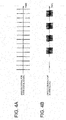
Fig. 4A is a graph showing a temporal change of an analog signal for turn-signal sound obtained by integrating the pulse signal for turn-signal sound; -
Fig. 4B is a graph showing a temporal change of an analog signal for alarm sound obtained by integrating the pulse signal for alarm sound; -
Fig. 5 is a graph showing a signal obtained by summing the analog signal for turn-signal sound and the analog signal for alarm sound shown inFigs. 4A and 4B , respectively; -
Fig. 6 is a graph with an enlarged temporal axis of a portion A shown inFig. 5 ; -
Fig. 7 is a graph with an enlarged temporal axis of a portion B shown inFig. 5 ; -
Fig. 8 is a graph showing a result of a frequency analysis on a turn-signal sound of a mechanical relay; and -
Fig. 9 is a graph showing a processed result of a frequency analysis of the turn-signal sound of the mechanical relay. - The following will describe an embodiment of the present invention in reference with the drawings. As shown in the drawing, a sound-generating device 1 for generating turn-signal sound of a vehicle (herein after called a sound-generating device 1) includes a CPU (central processing unit) 2, a plurality of integration circuits 31-34, a summation circuit 4, a
speaker 5 and a voltage-dividing resistor R. TheCPU 2 includes a PPG (pulse pattern generator)port 21 for outputting a pulse signal for the turn-signal sound and S/G (sound generator) ports 22-24. - Although the
PPG port 21 burdens theCPU 2, thePPG port 2 1 can determine a high-level period and a low-level period of the pulse individually, thus the frequency and the duty ratio of the pulse can be controlled in detail. ThisPPG port 21 intermittently outputs (e.g. outputs every 5.2 kHz) the pulse signal for turn-signal sound having fast-varying frequency and duty ratio, as shown inFig. 2A . On the other hand, the frequency and the duty ratio of the pulse cannot be controlled by the S/G ports 22-24 although they do not put much load on theCPU 2. Each of the S/G ports 22-24 intermittently outputs the pulse signal for alarm sound having the constant frequency and the constant duty ratio (e.g. the frequency of 700Hz and the duty ratio of 50%), as shown inFig. 3A . - The integration circuit 31-34 described above is a well-known CR filter constituted of a capacitor and a resistor. The above-described
integration circuit 31 integrates the above-described pulse signal for turn-signal sound to convert the pulse signal for turn-signal sound into an analog signal for turn-signal sound. The frequency of this analog signal for turn-signal sound is determined by the frequency of the pulse signal for turn-signal sound. In addition, the amplitude of the analog signal for turn-signal sound is determined by the duty ratio of the pulse signal for turn-signal sound. Thus, by integrating the pulse signal for turn-signal sound having the fast-varying frequency and duty ratio, there is obtained the analog signal for turn-signal sound having the fast-varying frequency and amplitude, as shown inFig. 2B . - Furthermore, the integration circuit 32-34 described above is arranged to integrate the pulse signal for alarm sound which is outputted from the S/G port 22-24 to convert the pulse signal for alarm sound into the analog signal for alarm sound. By integrating the pulse signal having the constant frequency and the constant duty ratio, there is obtained the analog signal for alarm sound having the constant frequency and the constant amplitude, as shown in
Fig. 3B . - The summation circuit 4 described above is a well-known summation circuit which is arranged to sum up the plurality of analog signals inputted to the summation circuit 4. The summation circuit 4 sums up the analog signal for turn-signal sound and the analog signal for alarm sound which were outputted from the integration circuits 31-34, and then outputs a summed signal to the
speaker 5. Each of the voltage-dividing resistors R described above is arranged between the respective integration circuits 31-34 and the summation circuit 4. The voltage-dividing resistor R divides a voltage of the analog signal for turn-signal sound and the analog signal for alarm sound which are outputted from the integration circuits 31-34, respectively, which are then outputted to the summation circuit 4. By adjusting the voltage-dividing resistor R, the magnitude of the analog signal for turn-signal sound and the analog signal for alarm sound can be adjusted before being provided to the summation circuit 4. In this embodiment, the voltage-dividing resistor R is adjusted so that the magnitude of the analog signal for turn-signal sound is larger than the magnitude of the analog signal for alarm sound. - The following will describe the operation of the sound-generating device 1 described above. When a turn-signal switch not shown is turned on, the
CPU 2 outputs from thePPG port 21 the pulse signal for turn-signal sound having the fast-varying frequency and duty ratio. Then, the pulse signal for turn-signal sound is provided to theintegration circuit 31, in which the pulse signal for turn-signal sound is integrated and converted into the analog signal for turn-signal sound. As described above, the frequency of the analog signal for turn-signal sound is determined by the frequency of the pulse signal for turn-signal sound, and the amplitude of the analog signal for turn-signal sound is determined by the duty ratio of the pulse signal for turn-signal sound. Thus, by integrating the pulse signal for turn-signal sound having the fast-varying frequency and duty ratio, there is obtained the analog signal for turn-signal sound having the fast-varying frequency and amplitude, as shown inFig. 2B . - Then, the voltage of the obtained analog signal for turn-signal sound is divided by the voltage-dividing resistor R, and then the analog signal for turn-signal sound is provided to the summation circuit 4. If there is no analog signal for alarm sound provided from the integration circuits 32-34, then the summation circuit 4 outputs the analog signal for turn-signal sound to the
speaker 5. Then, when the analog signal for turn-signal sound is inputted to thespeaker 5, thespeaker 5 intermittently outputs a sound having the fast-varying frequency and sound-volume corresponding to the analog signal for turn-signal sound. Due to a characteristic property of a human ear, when a person hears the sound having the fast-varying frequency, the person recognizes as if the sound with a plurality of frequencies are heard simultaneously. Therefore, by controlling the frequency and the duty ratio of the pulse signal for turn-signal sound, the tone of the turn-signal sound can be adjusted. Thus, the turn-signal sound close to the operating sound of the mechanical relay can be outputted from thespeaker 5, so the user's demand for the tone of the turn-signal sound can be satisfied. - When an alarm is activated, the pulse signal for alarm sound having the constant frequency and the constant duty ratio is intermittently outputted from the S/G port 22-24 by the
CPU 2, as shown inFig. 3A , and provided to the integration circuit 32-34. The pulse signal for alarm sound is then integrated by the integration circuit 32-34 and converted into the analog signal for alarm sound. By integrating the pulse signal for alarm sound having the constant frequency and the constant duty ratio, there is obtained the analog signal for alarm sound having the constant frequency and the constant amplitude, as shown inFig. 3B . - Next, the voltage of the obtained analog signal for alarm sound is divided by the voltage-dividing resistor R, and then the analog signal for alarm sound is provided to the summation circuit 4. If there is no analog signal for turn-signal sound outputted from the
integration circuit 31, and if there is no more than one analog signal for alarm sound outputted from the integration circuit 32-34, then the summation circuit 4 outputs the analog signal for alarm sound to thespeaker 5. Then, when the analog signal for alarm sound is inputted to thespeaker 5 and thespeaker 5 intermittently outputs sound having the constant frequency and the constant sound-volume according to the analog signal for alarm sound. - On the other hand, when the analog signal for turn-signal sound and the analog signal for alarm sound are outputted to the summation circuit 4 at the same time, as shown in
Figs. 4A and 4B , the summation circuit 4 sums up the analog signal for turn-signal sound and the analog signal for alarm sound, as shown inFig. 5 . The resulting summed signal is constituted of the analog signal for turn-signal sound having the fast-varying frequency and amplitude, which is shown inFig. 6 , superposed on the analog signal for alarm sound having the constant frequency and the constant amplitude. Thus, the summed signal has a wave shape as shown inFig. 7 . Then, the summation circuit 4 outputs the summed signal to thespeaker 5. In such manner, the turn-signal sound and the alarm sound can be outputted simultaneously from thespeaker 5. - Referring now to
Fig. 8 andFig. 9 , the following will explain how the frequency of the pulse signal for turn-signal sound is determined in order to output the turn-signal sound close to the operating sound of the mechanical relay from thespeaker 5.Fig. 8 shows a result of the frequency analysis on the turn-signal sound of the mechanical relay. As shown inFig. 8 , the turn-signal sound of the mechanical relay is widely distributed across the audible region. Therefore, by determining the frequency and the duty ratio of the pulse signal for turn-signal sound so as to vary according to the frequency and the sound pressure corresponding to the frequency included in the operating sound of the mechanical relay (i.e. to vary fast within 100Hz to 10000Hz), thespeaker 5 can output the turn-signal sound close to the operating sound of the mechanical relay. - However, it is not easy to adjust the pulse signal for turn-signal sound to vary across the wide audible region in a short period of time for producing the turn-signal sound. Thus, it is necessary to eliminate the unnecessary frequency components from the pulse signal for turn-signal sound while leaving the audibly efficient frequency components. Therefore, in this embodiment, the frequency components which are out of the frequency range of the speaker 5 (e.g. the frequency components equal or smaller than 500Hz) are eliminated from the pulse signal for turn-signal sound. In addition, considering the fact that the square wave contains many odd harmonics, the frequency components corresponding to the odd multiple of the corresponding frequency are also eliminated.
- The following is an example of the elimination of the odd multiple frequency components. Firstly, a frequency analysis is conducted on the turn-signal sound of the mechanical relay having the frequency property as shown in
Fig. 8 , by eliminating the odd multiple frequency components while leaving only the fundamental frequency, and subjecting to a dynamic control process using a noise gate or a compressor. The result of the analysis shown inFig. 9 shows that, before processing, the frequency components are widely distributed across the audible region, whereas after the processing, only the specific frequency components are distributed forming peaks. Thus, by controlling the pulse signal for turn-signal sound to vary according to the frequency peaks, the odd multiple frequency components of the corresponding frequency can be eliminated. - As described above, the frequency components which are out of the frequency range of the
speaker 5 are eliminated from the pulse signal for turn-signal sound. Thus, the time for outputting the pulse signal for turn-signal sound with the frequency components which cannot be produced by thespeaker 5 can be eliminated, thus the time can be used efficiently for outputting the pulse signal for turn-signal sound having the frequency components which can be produced by thespeaker 5. As a result, high-quality turn-signal sound can be produced. - Furthermore, considering the fact that the pulse signal contains the odd harmonics, the odd multiple frequency components of the corresponding frequency are eliminated from the pulse signal for turn-signal sound. Thus, the time for outputting the unnecessary pulse signal for turn-signal sound can be eliminated, thus the time can be used efficiently for outputting the efficient pulse signal for turn-signal sound. As a result, high-quality turn-signal sound can be produced.
- In the embodiment described herein, the analog signal for turn-signal sound and the analog signal for alarm sound are summed together to simultaneously output the turn-signal sound and the alarm sound from the
speaker 5. However, the present invention is not limited to this regard, and for example, two speakers may be used to output the turn-signal sound and the alarm sound separately. - In addition, in the embodiment described herein the frequency distribution varies across the audible region. However, the present invention is not limited to this regard, and the frequency distribution may vary according to the user's demand.
- It should be understood that the embodiment included herein is only a representative embodiment, and is not intended to limit the present invention. That is, the present invention may be modified in a variety of ways and performed within a scope of the present invention.
-
- 1
- sound-generating device for turn-signal sound of vehicle
- 2
- CPU (central processing unit)
- 4
- summation circuit (summation means)
- 5
- speaker
- 31
- integration circuit (integration means)
Claims (4)
- A method for generating turn-signal sound of a vehicle, comprising the steps of:outputting a pulse signal for turn-signal sound from a pulse pattern generator, the pulse signal for turn-signal sound having varying frequency and duty ratio;converting the pulse signal for turn-signal sound into an analog signal for turn-signal sound by integrating the pulse signal for turn-signal sound; andoutputting the analog signal for turn-signal sound to a speaker.
- The method as claimed in claim 1, further comprising the steps of:outputting a pulse signal for alarm sound from a sound generator, the pulse signal for alarm sound having the constant frequency and the constant duty ratio;converting the pulse signal for alarm sound into an analog signal for alarm sound by integrating the pulse signal for alarm sound;summing up the analog signal for turn-signal sound and the analog signal for alarm sound; andoutputting the summed signal instead of the analog signal for turn-signal sound to the speaker.
- The method as claimed in claim 1 or 2, wherein the pulse signal for turn-signal sound outputted from the pulse pattern generator has the frequency and the duty ratio arranged to vary according to the frequency and the sound pressure corresponding to the frequency included in an operating sound of a mechanical relay.
- A device for generating turn-signal sound of a vehicle, comprising:a central processing unit for outputting from a pulse pattern generator a pulse signal for turn-signal sound having varying frequency and duty ratio;an integration unit for integrating the pulse signal for turn-signal sound to convert the pulse signal for turn-signal sound into an analog signal for turn-signal sound; anda speaker to which the analog signal for turn-signal sound is outputted.
Applications Claiming Priority (2)
| Application Number | Priority Date | Filing Date | Title |
|---|---|---|---|
| JP2009205209A JP5325053B2 (en) | 2009-09-04 | 2009-09-04 | Turn sound blowing method for automobile and turn sound blowing device for automobile |
| PCT/JP2010/064343 WO2011027688A1 (en) | 2009-09-04 | 2010-08-25 | Method for producing sounds for turn signal sounds for an automobile and sounder for turn signal sounds for an automobile |
Publications (3)
| Publication Number | Publication Date |
|---|---|
| EP2476586A1 true EP2476586A1 (en) | 2012-07-18 |
| EP2476586A4 EP2476586A4 (en) | 2016-11-30 |
| EP2476586B1 EP2476586B1 (en) | 2020-04-15 |
Family
ID=43649227
Family Applications (1)
| Application Number | Title | Priority Date | Filing Date |
|---|---|---|---|
| EP10813637.5A Active EP2476586B1 (en) | 2009-09-04 | 2010-08-25 | Method for producing sounds for turn signal sounds for an automobile and sounder for turn signal sounds for an automobile |
Country Status (5)
| Country | Link |
|---|---|
| US (1) | US8638208B2 (en) |
| EP (1) | EP2476586B1 (en) |
| JP (1) | JP5325053B2 (en) |
| CN (1) | CN102448772B (en) |
| WO (1) | WO2011027688A1 (en) |
Families Citing this family (10)
| Publication number | Priority date | Publication date | Assignee | Title |
|---|---|---|---|---|
| JP5746583B2 (en) * | 2011-08-01 | 2015-07-08 | 矢崎総業株式会社 | Operating sound generator |
| JP5699920B2 (en) * | 2011-12-05 | 2015-04-15 | 株式会社デンソー | Vehicle acoustic device |
| JP5974369B2 (en) * | 2012-12-26 | 2016-08-23 | カルソニックカンセイ株式会社 | Buzzer output control device and buzzer output control method |
| JP6111955B2 (en) * | 2013-09-27 | 2017-04-12 | アンデン株式会社 | Vehicle approach notification device |
| US9204521B2 (en) * | 2014-01-22 | 2015-12-01 | Tavi Salomon | Adapting turn signal |
| US10368327B2 (en) | 2014-05-14 | 2019-07-30 | Satixfy Israel Ltd. | Method and system for signal communications |
| CN106664135B (en) | 2014-05-14 | 2020-02-07 | 萨迪斯飞以色列有限公司 | Method for exchanging communications between a satellite and a terminal associated therewith |
| KR101668610B1 (en) * | 2015-12-03 | 2016-10-24 | 주식회사 원더풀플랫폼 | System for controlling operation sound of turn signal lamp of vehicle |
| CN111775828B (en) * | 2020-07-15 | 2026-01-02 | 杭叉集团股份有限公司 | A vehicle, a turn signal warning device, and a control method |
| KR20250173771A (en) * | 2024-06-04 | 2025-12-11 | 박남숙 | Vehicle turn signal sound control system |
Family Cites Families (12)
| Publication number | Priority date | Publication date | Assignee | Title |
|---|---|---|---|---|
| CN2060129U (en) * | 1989-12-27 | 1990-08-08 | 宝忠会 | Adjustable electronic sound and scintillator for automobile steering lamp |
| CN2196054Y (en) * | 1994-03-07 | 1995-05-03 | 傅亚文 | Speech reading, alarm and instructing device for motor-driven vehicle |
| JPH0922289A (en) * | 1995-07-04 | 1997-01-21 | Uniden Corp | Driving method and driving device for sounding body |
| JPH09301068A (en) * | 1996-05-13 | 1997-11-25 | Niles Parts Co Ltd | Electronic flasher device |
| JPH10214090A (en) * | 1997-01-31 | 1998-08-11 | Kansei Corp | Buzzer driving circuit |
| US5986540A (en) * | 1997-09-18 | 1999-11-16 | Nakagaki; Koutaro | Sound signal generating device |
| TW469689B (en) * | 1998-11-04 | 2001-12-21 | Rohm Co Ltd | Audio amplifier circuit and audio device using the circuit |
| CN2736213Y (en) * | 2002-05-27 | 2005-10-26 | 雅马哈株式会社 | Vehicle capable of informing its state by hearing |
| JP3876767B2 (en) | 2002-06-06 | 2007-02-07 | ヤマハ株式会社 | Notification sound generation method and apparatus, and notification sound generation program |
| JP4577615B2 (en) * | 2005-10-21 | 2010-11-10 | 日本精機株式会社 | Vehicle information providing device |
| CN1986285B (en) * | 2006-12-22 | 2010-04-07 | 哈尔滨工业大学 | Electronic turning warning squealer-flash for automobile |
| WO2009019945A1 (en) * | 2007-08-07 | 2009-02-12 | Rohm Co., Ltd. | Light source turn-on/off controller |
-
2009
- 2009-09-04 JP JP2009205209A patent/JP5325053B2/en not_active Expired - Fee Related
-
2010
- 2010-08-25 US US13/379,190 patent/US8638208B2/en not_active Expired - Fee Related
- 2010-08-25 EP EP10813637.5A patent/EP2476586B1/en active Active
- 2010-08-25 WO PCT/JP2010/064343 patent/WO2011027688A1/en not_active Ceased
- 2010-08-25 CN CN201080023465.9A patent/CN102448772B/en active Active
Non-Patent Citations (1)
| Title |
|---|
| See references of WO2011027688A1 * |
Also Published As
| Publication number | Publication date |
|---|---|
| JP5325053B2 (en) | 2013-10-23 |
| JP2011056967A (en) | 2011-03-24 |
| WO2011027688A1 (en) | 2011-03-10 |
| CN102448772B (en) | 2015-04-29 |
| US20120098656A1 (en) | 2012-04-26 |
| CN102448772A (en) | 2012-05-09 |
| EP2476586A4 (en) | 2016-11-30 |
| EP2476586B1 (en) | 2020-04-15 |
| US8638208B2 (en) | 2014-01-28 |
Similar Documents
| Publication | Publication Date | Title |
|---|---|---|
| EP2476586A1 (en) | Method for producing sounds for turn signal sounds for an automobile and sounder for turn signal sounds for an automobile | |
| US9580010B2 (en) | Vehicle approach notification apparatus | |
| CN107533839B (en) | Method and device for processing ambient sound | |
| EP1947642B1 (en) | Active noise control system | |
| CN111081213A (en) | New energy vehicle, active sound system and active sound control method thereof | |
| JP2003264883A (en) | Audio processing device and audio processing method | |
| JP4440333B1 (en) | hearing aid | |
| US20170134858A1 (en) | Special Sound Producing Device | |
| JP6510241B2 (en) | Alarm device | |
| EP3070709A1 (en) | Sound masking apparatus and sound masking method | |
| CN101149918B (en) | Sound processing device with singing practice function | |
| Schwendicke et al. | Temporal masking characteristics of whole body vibration perception | |
| JP2012063614A (en) | Masking sound generation device | |
| JP4977066B2 (en) | Voice guidance device for vehicles | |
| US20070146123A1 (en) | Multi-tone back-up alarm | |
| JP7685149B2 (en) | Vehicle sound generating device control device | |
| JP3836849B2 (en) | hearing aid | |
| KR20100005997U (en) | White noise out device | |
| JP6510242B2 (en) | Sound effect ringer | |
| JP2024135676A (en) | Communication Equipment | |
| JP2007269044A (en) | On-vehicle sounding device | |
| JP3616797B2 (en) | Auditory organ function promoting device | |
| JP2025169687A (en) | Information notification device, information notification program, information notification method, and information notification system | |
| Baldwin | Auditory perception. | |
| Weisser | Auditory information loss in real-world listening environments |
Legal Events
| Date | Code | Title | Description |
|---|---|---|---|
| PUAI | Public reference made under article 153(3) epc to a published international application that has entered the european phase |
Free format text: ORIGINAL CODE: 0009012 |
|
| 17P | Request for examination filed |
Effective date: 20111017 |
|
| AK | Designated contracting states |
Kind code of ref document: A1 Designated state(s): AL AT BE BG CH CY CZ DE DK EE ES FI FR GB GR HR HU IE IS IT LI LT LU LV MC MK MT NL NO PL PT RO SE SI SK SM TR |
|
| DAX | Request for extension of the european patent (deleted) | ||
| RA4 | Supplementary search report drawn up and despatched (corrected) |
Effective date: 20161027 |
|
| RIC1 | Information provided on ipc code assigned before grant |
Ipc: B60Q 5/00 20060101AFI20161021BHEP Ipc: G10K 9/18 20060101ALI20161021BHEP Ipc: B60Q 1/34 20060101ALI20161021BHEP Ipc: B60R 16/02 20060101ALI20161021BHEP |
|
| STAA | Information on the status of an ep patent application or granted ep patent |
Free format text: STATUS: EXAMINATION IS IN PROGRESS |
|
| 17Q | First examination report despatched |
Effective date: 20180606 |
|
| GRAP | Despatch of communication of intention to grant a patent |
Free format text: ORIGINAL CODE: EPIDOSNIGR1 |
|
| STAA | Information on the status of an ep patent application or granted ep patent |
Free format text: STATUS: GRANT OF PATENT IS INTENDED |
|
| INTG | Intention to grant announced |
Effective date: 20191212 |
|
| RIN1 | Information on inventor provided before grant (corrected) |
Inventor name: IKEDA, NAOHISA |
|
| GRAS | Grant fee paid |
Free format text: ORIGINAL CODE: EPIDOSNIGR3 |
|
| GRAA | (expected) grant |
Free format text: ORIGINAL CODE: 0009210 |
|
| STAA | Information on the status of an ep patent application or granted ep patent |
Free format text: STATUS: THE PATENT HAS BEEN GRANTED |
|
| RIN1 | Information on inventor provided before grant (corrected) |
Inventor name: IKEDA, NAOHISA |
|
| AK | Designated contracting states |
Kind code of ref document: B1 Designated state(s): AL AT BE BG CH CY CZ DE DK EE ES FI FR GB GR HR HU IE IS IT LI LT LU LV MC MK MT NL NO PL PT RO SE SI SK SM TR |
|
| REG | Reference to a national code |
Ref country code: CH Ref legal event code: EP Ref country code: GB Ref legal event code: FG4D |
|
| REG | Reference to a national code |
Ref country code: DE Ref legal event code: R096 Ref document number: 602010063942 Country of ref document: DE |
|
| REG | Reference to a national code |
Ref country code: IE Ref legal event code: FG4D |
|
| REG | Reference to a national code |
Ref country code: AT Ref legal event code: REF Ref document number: 1256898 Country of ref document: AT Kind code of ref document: T Effective date: 20200515 |
|
| REG | Reference to a national code |
Ref country code: NL Ref legal event code: MP Effective date: 20200415 |
|
| REG | Reference to a national code |
Ref country code: LT Ref legal event code: MG4D |
|
| PG25 | Lapsed in a contracting state [announced via postgrant information from national office to epo] |
Ref country code: IS Free format text: LAPSE BECAUSE OF FAILURE TO SUBMIT A TRANSLATION OF THE DESCRIPTION OR TO PAY THE FEE WITHIN THE PRESCRIBED TIME-LIMIT Effective date: 20200815 Ref country code: SE Free format text: LAPSE BECAUSE OF FAILURE TO SUBMIT A TRANSLATION OF THE DESCRIPTION OR TO PAY THE FEE WITHIN THE PRESCRIBED TIME-LIMIT Effective date: 20200415 Ref country code: NO Free format text: LAPSE BECAUSE OF FAILURE TO SUBMIT A TRANSLATION OF THE DESCRIPTION OR TO PAY THE FEE WITHIN THE PRESCRIBED TIME-LIMIT Effective date: 20200715 Ref country code: GR Free format text: LAPSE BECAUSE OF FAILURE TO SUBMIT A TRANSLATION OF THE DESCRIPTION OR TO PAY THE FEE WITHIN THE PRESCRIBED TIME-LIMIT Effective date: 20200716 Ref country code: PT Free format text: LAPSE BECAUSE OF FAILURE TO SUBMIT A TRANSLATION OF THE DESCRIPTION OR TO PAY THE FEE WITHIN THE PRESCRIBED TIME-LIMIT Effective date: 20200817 Ref country code: LT Free format text: LAPSE BECAUSE OF FAILURE TO SUBMIT A TRANSLATION OF THE DESCRIPTION OR TO PAY THE FEE WITHIN THE PRESCRIBED TIME-LIMIT Effective date: 20200415 Ref country code: FI Free format text: LAPSE BECAUSE OF FAILURE TO SUBMIT A TRANSLATION OF THE DESCRIPTION OR TO PAY THE FEE WITHIN THE PRESCRIBED TIME-LIMIT Effective date: 20200415 Ref country code: NL Free format text: LAPSE BECAUSE OF FAILURE TO SUBMIT A TRANSLATION OF THE DESCRIPTION OR TO PAY THE FEE WITHIN THE PRESCRIBED TIME-LIMIT Effective date: 20200415 |
|
| REG | Reference to a national code |
Ref country code: AT Ref legal event code: MK05 Ref document number: 1256898 Country of ref document: AT Kind code of ref document: T Effective date: 20200415 |
|
| PG25 | Lapsed in a contracting state [announced via postgrant information from national office to epo] |
Ref country code: HR Free format text: LAPSE BECAUSE OF FAILURE TO SUBMIT A TRANSLATION OF THE DESCRIPTION OR TO PAY THE FEE WITHIN THE PRESCRIBED TIME-LIMIT Effective date: 20200415 Ref country code: LV Free format text: LAPSE BECAUSE OF FAILURE TO SUBMIT A TRANSLATION OF THE DESCRIPTION OR TO PAY THE FEE WITHIN THE PRESCRIBED TIME-LIMIT Effective date: 20200415 Ref country code: BG Free format text: LAPSE BECAUSE OF FAILURE TO SUBMIT A TRANSLATION OF THE DESCRIPTION OR TO PAY THE FEE WITHIN THE PRESCRIBED TIME-LIMIT Effective date: 20200715 |
|
| PG25 | Lapsed in a contracting state [announced via postgrant information from national office to epo] |
Ref country code: AL Free format text: LAPSE BECAUSE OF FAILURE TO SUBMIT A TRANSLATION OF THE DESCRIPTION OR TO PAY THE FEE WITHIN THE PRESCRIBED TIME-LIMIT Effective date: 20200415 |
|
| REG | Reference to a national code |
Ref country code: DE Ref legal event code: R097 Ref document number: 602010063942 Country of ref document: DE |
|
| PG25 | Lapsed in a contracting state [announced via postgrant information from national office to epo] |
Ref country code: EE Free format text: LAPSE BECAUSE OF FAILURE TO SUBMIT A TRANSLATION OF THE DESCRIPTION OR TO PAY THE FEE WITHIN THE PRESCRIBED TIME-LIMIT Effective date: 20200415 Ref country code: SM Free format text: LAPSE BECAUSE OF FAILURE TO SUBMIT A TRANSLATION OF THE DESCRIPTION OR TO PAY THE FEE WITHIN THE PRESCRIBED TIME-LIMIT Effective date: 20200415 Ref country code: DK Free format text: LAPSE BECAUSE OF FAILURE TO SUBMIT A TRANSLATION OF THE DESCRIPTION OR TO PAY THE FEE WITHIN THE PRESCRIBED TIME-LIMIT Effective date: 20200415 Ref country code: CZ Free format text: LAPSE BECAUSE OF FAILURE TO SUBMIT A TRANSLATION OF THE DESCRIPTION OR TO PAY THE FEE WITHIN THE PRESCRIBED TIME-LIMIT Effective date: 20200415 Ref country code: ES Free format text: LAPSE BECAUSE OF FAILURE TO SUBMIT A TRANSLATION OF THE DESCRIPTION OR TO PAY THE FEE WITHIN THE PRESCRIBED TIME-LIMIT Effective date: 20200415 Ref country code: IT Free format text: LAPSE BECAUSE OF FAILURE TO SUBMIT A TRANSLATION OF THE DESCRIPTION OR TO PAY THE FEE WITHIN THE PRESCRIBED TIME-LIMIT Effective date: 20200415 Ref country code: RO Free format text: LAPSE BECAUSE OF FAILURE TO SUBMIT A TRANSLATION OF THE DESCRIPTION OR TO PAY THE FEE WITHIN THE PRESCRIBED TIME-LIMIT Effective date: 20200415 Ref country code: AT Free format text: LAPSE BECAUSE OF FAILURE TO SUBMIT A TRANSLATION OF THE DESCRIPTION OR TO PAY THE FEE WITHIN THE PRESCRIBED TIME-LIMIT Effective date: 20200415 |
|
| PLBE | No opposition filed within time limit |
Free format text: ORIGINAL CODE: 0009261 |
|
| STAA | Information on the status of an ep patent application or granted ep patent |
Free format text: STATUS: NO OPPOSITION FILED WITHIN TIME LIMIT |
|
| PG25 | Lapsed in a contracting state [announced via postgrant information from national office to epo] |
Ref country code: PL Free format text: LAPSE BECAUSE OF FAILURE TO SUBMIT A TRANSLATION OF THE DESCRIPTION OR TO PAY THE FEE WITHIN THE PRESCRIBED TIME-LIMIT Effective date: 20200415 Ref country code: SK Free format text: LAPSE BECAUSE OF FAILURE TO SUBMIT A TRANSLATION OF THE DESCRIPTION OR TO PAY THE FEE WITHIN THE PRESCRIBED TIME-LIMIT Effective date: 20200415 |
|
| 26N | No opposition filed |
Effective date: 20210118 |
|
| PG25 | Lapsed in a contracting state [announced via postgrant information from national office to epo] |
Ref country code: MC Free format text: LAPSE BECAUSE OF FAILURE TO SUBMIT A TRANSLATION OF THE DESCRIPTION OR TO PAY THE FEE WITHIN THE PRESCRIBED TIME-LIMIT Effective date: 20200415 |
|
| REG | Reference to a national code |
Ref country code: CH Ref legal event code: PL |
|
| GBPC | Gb: european patent ceased through non-payment of renewal fee |
Effective date: 20200825 |
|
| PG25 | Lapsed in a contracting state [announced via postgrant information from national office to epo] |
Ref country code: CH Free format text: LAPSE BECAUSE OF NON-PAYMENT OF DUE FEES Effective date: 20200831 Ref country code: LI Free format text: LAPSE BECAUSE OF NON-PAYMENT OF DUE FEES Effective date: 20200831 Ref country code: LU Free format text: LAPSE BECAUSE OF NON-PAYMENT OF DUE FEES Effective date: 20200825 |
|
| REG | Reference to a national code |
Ref country code: BE Ref legal event code: MM Effective date: 20200831 |
|
| PG25 | Lapsed in a contracting state [announced via postgrant information from national office to epo] |
Ref country code: SI Free format text: LAPSE BECAUSE OF FAILURE TO SUBMIT A TRANSLATION OF THE DESCRIPTION OR TO PAY THE FEE WITHIN THE PRESCRIBED TIME-LIMIT Effective date: 20200415 |
|
| PG25 | Lapsed in a contracting state [announced via postgrant information from national office to epo] |
Ref country code: IE Free format text: LAPSE BECAUSE OF NON-PAYMENT OF DUE FEES Effective date: 20200825 Ref country code: GB Free format text: LAPSE BECAUSE OF NON-PAYMENT OF DUE FEES Effective date: 20200825 Ref country code: BE Free format text: LAPSE BECAUSE OF NON-PAYMENT OF DUE FEES Effective date: 20200831 |
|
| PG25 | Lapsed in a contracting state [announced via postgrant information from national office to epo] |
Ref country code: TR Free format text: LAPSE BECAUSE OF FAILURE TO SUBMIT A TRANSLATION OF THE DESCRIPTION OR TO PAY THE FEE WITHIN THE PRESCRIBED TIME-LIMIT Effective date: 20200415 Ref country code: MT Free format text: LAPSE BECAUSE OF FAILURE TO SUBMIT A TRANSLATION OF THE DESCRIPTION OR TO PAY THE FEE WITHIN THE PRESCRIBED TIME-LIMIT Effective date: 20200415 Ref country code: CY Free format text: LAPSE BECAUSE OF FAILURE TO SUBMIT A TRANSLATION OF THE DESCRIPTION OR TO PAY THE FEE WITHIN THE PRESCRIBED TIME-LIMIT Effective date: 20200415 |
|
| PG25 | Lapsed in a contracting state [announced via postgrant information from national office to epo] |
Ref country code: MK Free format text: LAPSE BECAUSE OF FAILURE TO SUBMIT A TRANSLATION OF THE DESCRIPTION OR TO PAY THE FEE WITHIN THE PRESCRIBED TIME-LIMIT Effective date: 20200415 |
|
| PGFP | Annual fee paid to national office [announced via postgrant information from national office to epo] |
Ref country code: DE Payment date: 20240702 Year of fee payment: 15 |
|
| PGFP | Annual fee paid to national office [announced via postgrant information from national office to epo] |
Ref country code: FR Payment date: 20250703 Year of fee payment: 16 |
|
| REG | Reference to a national code |
Ref country code: DE Ref legal event code: R119 Ref document number: 602010063942 Country of ref document: DE |