EP2476576A2 - Charging apparatus - Google Patents
Charging apparatus Download PDFInfo
- Publication number
- EP2476576A2 EP2476576A2 EP12150744A EP12150744A EP2476576A2 EP 2476576 A2 EP2476576 A2 EP 2476576A2 EP 12150744 A EP12150744 A EP 12150744A EP 12150744 A EP12150744 A EP 12150744A EP 2476576 A2 EP2476576 A2 EP 2476576A2
- Authority
- EP
- European Patent Office
- Prior art keywords
- charging
- charging apparatus
- protrusion
- base
- target
- Prior art date
- Legal status (The legal status is an assumption and is not a legal conclusion. Google has not performed a legal analysis and makes no representation as to the accuracy of the status listed.)
- Withdrawn
Links
Images


Classifications
-
- B—PERFORMING OPERATIONS; TRANSPORTING
- B60—VEHICLES IN GENERAL
- B60L—PROPULSION OF ELECTRICALLY-PROPELLED VEHICLES; SUPPLYING ELECTRIC POWER FOR AUXILIARY EQUIPMENT OF ELECTRICALLY-PROPELLED VEHICLES; ELECTRODYNAMIC BRAKE SYSTEMS FOR VEHICLES IN GENERAL; MAGNETIC SUSPENSION OR LEVITATION FOR VEHICLES; MONITORING OPERATING VARIABLES OF ELECTRICALLY-PROPELLED VEHICLES; ELECTRIC SAFETY DEVICES FOR ELECTRICALLY-PROPELLED VEHICLES
- B60L53/00—Methods of charging batteries, specially adapted for electric vehicles; Charging stations or on-board charging equipment therefor; Exchange of energy storage elements in electric vehicles
- B60L53/30—Constructional details of charging stations
- B60L53/305—Communication interfaces
-
- B—PERFORMING OPERATIONS; TRANSPORTING
- B60—VEHICLES IN GENERAL
- B60L—PROPULSION OF ELECTRICALLY-PROPELLED VEHICLES; SUPPLYING ELECTRIC POWER FOR AUXILIARY EQUIPMENT OF ELECTRICALLY-PROPELLED VEHICLES; ELECTRODYNAMIC BRAKE SYSTEMS FOR VEHICLES IN GENERAL; MAGNETIC SUSPENSION OR LEVITATION FOR VEHICLES; MONITORING OPERATING VARIABLES OF ELECTRICALLY-PROPELLED VEHICLES; ELECTRIC SAFETY DEVICES FOR ELECTRICALLY-PROPELLED VEHICLES
- B60L53/00—Methods of charging batteries, specially adapted for electric vehicles; Charging stations or on-board charging equipment therefor; Exchange of energy storage elements in electric vehicles
- B60L53/30—Constructional details of charging stations
- B60L53/31—Charging columns specially adapted for electric vehicles
-
- B—PERFORMING OPERATIONS; TRANSPORTING
- B60—VEHICLES IN GENERAL
- B60L—PROPULSION OF ELECTRICALLY-PROPELLED VEHICLES; SUPPLYING ELECTRIC POWER FOR AUXILIARY EQUIPMENT OF ELECTRICALLY-PROPELLED VEHICLES; ELECTRODYNAMIC BRAKE SYSTEMS FOR VEHICLES IN GENERAL; MAGNETIC SUSPENSION OR LEVITATION FOR VEHICLES; MONITORING OPERATING VARIABLES OF ELECTRICALLY-PROPELLED VEHICLES; ELECTRIC SAFETY DEVICES FOR ELECTRICALLY-PROPELLED VEHICLES
- B60L53/00—Methods of charging batteries, specially adapted for electric vehicles; Charging stations or on-board charging equipment therefor; Exchange of energy storage elements in electric vehicles
- B60L53/10—Methods of charging batteries, specially adapted for electric vehicles; Charging stations or on-board charging equipment therefor; Exchange of energy storage elements in electric vehicles characterised by the energy transfer between the charging station and the vehicle
- B60L53/14—Conductive energy transfer
- B60L53/16—Connectors, e.g. plugs or sockets, specially adapted for charging electric vehicles
-
- Y—GENERAL TAGGING OF NEW TECHNOLOGICAL DEVELOPMENTS; GENERAL TAGGING OF CROSS-SECTIONAL TECHNOLOGIES SPANNING OVER SEVERAL SECTIONS OF THE IPC; TECHNICAL SUBJECTS COVERED BY FORMER USPC CROSS-REFERENCE ART COLLECTIONS [XRACs] AND DIGESTS
- Y02—TECHNOLOGIES OR APPLICATIONS FOR MITIGATION OR ADAPTATION AGAINST CLIMATE CHANGE
- Y02T—CLIMATE CHANGE MITIGATION TECHNOLOGIES RELATED TO TRANSPORTATION
- Y02T10/00—Road transport of goods or passengers
- Y02T10/60—Other road transportation technologies with climate change mitigation effect
- Y02T10/70—Energy storage systems for electromobility, e.g. batteries
-
- Y—GENERAL TAGGING OF NEW TECHNOLOGICAL DEVELOPMENTS; GENERAL TAGGING OF CROSS-SECTIONAL TECHNOLOGIES SPANNING OVER SEVERAL SECTIONS OF THE IPC; TECHNICAL SUBJECTS COVERED BY FORMER USPC CROSS-REFERENCE ART COLLECTIONS [XRACs] AND DIGESTS
- Y02—TECHNOLOGIES OR APPLICATIONS FOR MITIGATION OR ADAPTATION AGAINST CLIMATE CHANGE
- Y02T—CLIMATE CHANGE MITIGATION TECHNOLOGIES RELATED TO TRANSPORTATION
- Y02T10/00—Road transport of goods or passengers
- Y02T10/60—Other road transportation technologies with climate change mitigation effect
- Y02T10/7072—Electromobility specific charging systems or methods for batteries, ultracapacitors, supercapacitors or double-layer capacitors
-
- Y—GENERAL TAGGING OF NEW TECHNOLOGICAL DEVELOPMENTS; GENERAL TAGGING OF CROSS-SECTIONAL TECHNOLOGIES SPANNING OVER SEVERAL SECTIONS OF THE IPC; TECHNICAL SUBJECTS COVERED BY FORMER USPC CROSS-REFERENCE ART COLLECTIONS [XRACs] AND DIGESTS
- Y02—TECHNOLOGIES OR APPLICATIONS FOR MITIGATION OR ADAPTATION AGAINST CLIMATE CHANGE
- Y02T—CLIMATE CHANGE MITIGATION TECHNOLOGIES RELATED TO TRANSPORTATION
- Y02T90/00—Enabling technologies or technologies with a potential or indirect contribution to GHG emissions mitigation
- Y02T90/10—Technologies relating to charging of electric vehicles
- Y02T90/12—Electric charging stations
-
- Y—GENERAL TAGGING OF NEW TECHNOLOGICAL DEVELOPMENTS; GENERAL TAGGING OF CROSS-SECTIONAL TECHNOLOGIES SPANNING OVER SEVERAL SECTIONS OF THE IPC; TECHNICAL SUBJECTS COVERED BY FORMER USPC CROSS-REFERENCE ART COLLECTIONS [XRACs] AND DIGESTS
- Y02—TECHNOLOGIES OR APPLICATIONS FOR MITIGATION OR ADAPTATION AGAINST CLIMATE CHANGE
- Y02T—CLIMATE CHANGE MITIGATION TECHNOLOGIES RELATED TO TRANSPORTATION
- Y02T90/00—Enabling technologies or technologies with a potential or indirect contribution to GHG emissions mitigation
- Y02T90/10—Technologies relating to charging of electric vehicles
- Y02T90/14—Plug-in electric vehicles
-
- Y—GENERAL TAGGING OF NEW TECHNOLOGICAL DEVELOPMENTS; GENERAL TAGGING OF CROSS-SECTIONAL TECHNOLOGIES SPANNING OVER SEVERAL SECTIONS OF THE IPC; TECHNICAL SUBJECTS COVERED BY FORMER USPC CROSS-REFERENCE ART COLLECTIONS [XRACs] AND DIGESTS
- Y02—TECHNOLOGIES OR APPLICATIONS FOR MITIGATION OR ADAPTATION AGAINST CLIMATE CHANGE
- Y02T—CLIMATE CHANGE MITIGATION TECHNOLOGIES RELATED TO TRANSPORTATION
- Y02T90/00—Enabling technologies or technologies with a potential or indirect contribution to GHG emissions mitigation
- Y02T90/10—Technologies relating to charging of electric vehicles
- Y02T90/16—Information or communication technologies improving the operation of electric vehicles
Definitions
- the present invention relates to charging apparatuses.
- Patent Document 1 discloses a charging station for electric vehicles, etc. installed in a parking lot.
- the charging station is provided with a plurality of charging poles.
- the charging poles include a conducting slot to which electric power is supplied from an outside power source.
- a bulletin body is provided over the charging poles.
- An advertising information section is formed on the obverse surface of the bulletin body so as to be capable of being displayed.
- Patent Document 1 Japanese Utility Model Registration No. 3163783
- the present invention has its object of providing a charging apparatus which holds an added value besides a charging function.
- a charging apparatus is a charging apparatus for charging electric power supplied from a power source to a charging target, including: a station section configured to supply the electric power to the charging target, wherein the station section includes: a base extending along a vertical direction; and a protrusion fixed to a part of the base and protruding frontward than the base, and space for disposing at least one article is formed on at least one of the upper side and the lower side of the protrusion.
- the protrusion can include an operating tool for operating to charge to the charging target.
- the charging apparatus can include a power source section configured to supply the electric power to the charging target.
- the station section can include a charging cable extending downward from the upper part of the base, and a charging connector to be connected to the charging target can be attached to a distal end of the charging cable.
- the at least one article can be at least one of a bulletin board, a monitor for displaying information, a shelf, a showcase for displaying goods, a reader for reading card information, and a mirror.
- the tip end of the right end part or the left end part of the protrusion can be notched to form a notched portion, and a catcher to which the charging connector can be caught is provided in the notched portion.
- the protrusion can decrease in vertical width as it goes frontward from the base and can have a rounded tip end.
- the operating tool can be arranged within a height range of 1000 ⁇ 200 mm from a ground plane of an operator.
- the charging apparatus according to the present invention can hold an added value besides a charging function when compared with a charging apparatus with no feature of the present invention.
- a charging apparatus 10 is capable of charging a battery boarded on an electric vehicle (one example of a charging target) 12, for example.
- the charging apparatus 10 can be installed not only at an existing filling station but also at a store, such as a convenience store, etc. and a parking lot.
- the installation site of the charging apparatus 10 may be indoor or outdoor.
- the charging apparatus 10 includes a power source section 20 and a station section 30.
- the power source section 20 is installed in a site apart from the station section 30.
- the power source section 20 is capable of converting commercial power source to electric power and supplying electric power necessary for charging a charging target to the station section 30.
- the station section 30 can supply the electric power supplied from the power source section 20 directly to the electric vehicle 12 or the like.
- the station section 30 includes a base 32, a protrusion 34, and a charging cable 38.
- the charging cable 38 extends downward from the upper part of the base 32. Further, a charging connector 36 to be connected to the charging target is attached to the distal end of the charging cable 38.
- the base 32 extends along a vertical direction (upward from the installation plane).
- Two pillars 40 are provided at the lower part of the base 32 (see FIGS. 3 and 6 ).
- the protrusion 34 is fixed to the base 32 at a predetermined height.
- the protrusion 34 is fixed to a part of the base 32.
- the protrusion 34 is composed of at least an upper plate 42a extending obliquely frontward and downward from the base 32 and a lower plate 42b extending obliquely frontward and upward from the base 32.
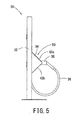
- the protrusion 34 protrudes frontward than the base 32. That is, as shown in FIG. 5 , the protrusion 34 is in triangular shape when viewed from the left side of the charging apparatus 10, and its vertical width (distance between the upper plate 42a and the lower plate 42b) decreases as it goes frontward from the base 32.
- the tip end part where the upper plate 42a is in contact with the lower plate 42b is rounded. The rounded tip end part is safe even if an operator comes in contact therewith.
- the right end part of the protrusion 34 is notched to form a notched portion.
- a catcher 44 for catching the charging connector 36 is provided in the notched portion.
- the protrusion 34 includes an operating tool 50 for operating to charge to the charging target.
- the operating tool 50 is provided on the upper plate 42a of the protrusion 34.
- Operation buttons (a start button 52a and a stop button 52b) for operation (charging operation) of the charging apparatus 10 are arranged on the operating tool 50 (see FIGS. 3-5 and 14 ).
- Each operation button arranged on the operating tool 50 is arranged within a height range of 1000 ⁇ 200 mm from the ground plane of an operator using the charging apparatus 10. It is noted that this height range may be preferably set to 1000 ⁇ 150 mm, and more preferably 1000 ⁇ 100 mm. With the operation buttons of the operating tool 50 arranged within this range, the charging apparatus 10 according to the present invention can provide favorable operability to an operator even in a wheelchair operating the charging apparatus 10.
- the charging connector 36 is housed in the right end part of the protrusion 34 set at the operation-easy height, it is easy for the operator to operate the charging apparatus 10.
- the protrusion 34 is provided on the front surface (the surface facing the operator when the operator operates the charging apparatus 10) of the station section 30, while a first rear door 54a is provided at a portion of the back surface (the surface opposite to the front surface of the station section 30) of the station section 30 which corresponds to the protrusion 34, as shown in FIG. 6 .
- a controller (not shown) for controlling the operating tool 50 arranged inside the protrusion 34 can be maintained.
- provision of the protrusion 34 protruding frontward than the base 32 in the operating tool 50 can enhance the operability of the charging apparatus 10.
- the charging cable 38 is arranged to extend downward from the upper right part of the base 32.
- the length of the charging cable 38 is set so as not to come into contact with the ground when the charging connector 36 at the distal end of the charging cable 38 is caught in the catcher 44.
- free space FS space for disposing an article (hereinafter referred to as "free space") FS is formed on the upper side of the part where the protrusion 34 is fixed.
- Any article appealing to a user of the charging apparatus 10 can be disposed in the free space FS.
- the article is a bulletin board 62a (see FIG. 9 ).
- the front surface of the bulletin board 62a is covered with a glass plate.
- Posting up an advertisement of a store on the bulletin board 62a enables an installation personnel (e.g., an owner of a filling station, a store, or a parking lot) to promote sales to the users.
- the article is a monitor 62b that displays information (see FIG. 10 ). Displaying an advertisement, a shop information map, a sightseeing map in the neighborhood, etc. on the monitor 62b enables the installation personnel to offer user's convenience.
- the article is a shelf 62c (see FIG. 11 ). Arranging the shelf 62c in the free space FS and decorating the shelf 62c with foliage plants enable the installation personnel to enhance the shop image.
- the article is a showcase 62d that displays goods (see FIG. 12 ).
- the owner of a store or the like as the installation personnel of the charging apparatus 10 can publicize the goods and services to the users.
- the article is a reader 62e (see FIG. 13 ).
- the reader 62e reads the information of a noncontact IC card (one example of cards). Providing the reader 62e in the free space FS enables the installation personnel to enhance the user's convenience.
- the article can be a mirror.
- the position where the free space FS is formed is not limited to the upper side of the part where the protrusion 34 is fixed. As far as the free space FS serves as space used for disposing the article, the position where the free space FS is formed can be located on the lower side of the part where the protrusion 34 is fixed. Further, the position where the free space FS is formed may be located on both the upper side and the lower side of the part where the protrusion 34 is fixed.
- the mirror can be disposed on the upper side of the part where the protrusion 34 is fixed, while the shelf 62c can be disposed on the lower side of the part where the protrusion 34 is fixed.
- two or more articles e.g., the mirror and the shelf
- the charging apparatus 10 since the free space FS used for disposing the article is formed in the station section 30, the charging apparatus 10 according to the present embodiment enables the installation personnel to hold an added value besides provision of the charging function to the user.
- the free space FS is provided on the front surface (the surface facing the operator when the operator operates the charging apparatus 10) of the station section 30, while a second rear door 54b is provided at a part of the back surface (the surface opposite to the front surface of the station section 30) of the station section 30 which corresponds to the free space FS.
- the charging apparatus 10 has been described with reference to FIGS. 1-13 . It is noted that the present invention is not limited to the charging apparatus 10 including the power source section 20. As far as the charging apparatus 10 includes the station section 30, the power source section 20 may be an outside power source for the charging apparatus 10.
- the operating tool 50 provided on the upper plate 42a of the protrusion 34 will be described next in detail with reference to FIGS. 1 , 4 , and 14-16 .
- the operating tool 50 is for operating to charge to the charging target.
- a plurality of first regions that display the operation of the apparatus step by step are provided along a first direction in the operating tool 50.
- One of the first regions indicates steps of operating operation buttons.
- the operation buttons are arranged in another region.
- regions A-D (the plurality of first regions) indicating respective operation steps of the charging apparatus 10 are arranged in line along the direction (the first direction) from left to right in the operating tool 50.
- Each region A-D is surrounded by a frame 70. Numbers corresponding to the respective operation steps are noted at the upper end parts of the respective regions A-D. Further, the summary of each operation step is noted on the right side of the corresponding number.
- steps of connecting a connector, which is to be connected to a charging target, to the charging target are indicated.
- steps of connecting the charging connector 36 to a charging target for example, the electric vehicle 12 or the like (information on inserting the charging connector 36 to the electric vehicle 12 and information on handling a lever of the charging connector 36) are indicated in group together with illustrations in the region A.
- a start switch (operation button) to start charging to a charging target is arranged, and a step of operating the start switch (step of operating the operation button) is indicated.
- the start button 52a (hardware switch) to start charging to the charging target is arranged, and a step of operating the start button 52a is indicated.
- the charged state of a charging target is indicated in the region C.
- an indicator 72 is arranged in the region C. The indicator 72 indicates the charged state of the charged target.
- Steps of removing the charging connector 36 from the charging target are indicated in group together with illustrations in the region D. It is noted that an emergency stop button 74 for emergency stop of the charging operation is arranged on the upper right side of the region D.
- the operation steps are displayed in the regions A-D, and the regions A-D are arranged in line along the first direction (e.g., direction from left to right).
- the operator can easily understand the flow of the operation steps.
- buttons and the indication of the steps of operating the buttons are separately arranged, the operator must understand the correspondence between the buttons and the explanation of the operation.
- the buttons and the indication of the steps of operating the buttons are arranged correspondingly, as in the region B.
- the operator is not required to understand the correspondence, thereby enabling intuitively operation.
- a second region displaying a step of stopping the operation is further arranged along a direction different from the first direction.
- a stop button to stop the operation is arranged in the second region.
- a region E second region
- a step of stopping the charging operation is indicated, and a stop switch to stop the charging operation is further arranged.
- the stop button 52b hardware switch
- the start button 52a is a button to be usually operated in accordance with the operation steps.
- the stop operation is unusual operation, and the stop button 52b is used only when necessary for the operator. Accordingly, the stop button 52b is arranged so as not to be located adjacent to the start button 52a.
- the region C and the region E are arranged along the second direction different from the first direction.
- the region E which includes the stop button 52b that is not usually used, is arranged along the direction (second direction) different from the direction in which the regions A-D, which indicate the usual operation steps, are arranged.
- the regions A-D may be arranged in line along the direction going down from above, while the region E is arranged on the right side of the region C. That is, the first direction may be set to go down from above, while the second direction is set to go right from left.
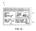
- the indicator 72 is a monochrome liquid crystal panel, for example. As shown in FIGS. 15 and 16 , a display screen 73 of the indicator 72 includes at least a first display region X1 and a second display region X2 arranged below the first display region X1.
- the first display region X1 displays information on the charged state of the charging target.
- the information on the charged state is status indicting, as shown in FIG. 15 for example: 1) character information, such as "Charging. Wait. Remaining Time: About 17 Minutes”; 2) an illustration indicating a charging rate of the buttery displayed on the right side of the character information; and 3) the progress of the charging operation indicated in the upper part of the first display region X1 ("Preparation”, “Testing", “Charging”, and "Finish”).
- the first display region X1 displays character information, such as "Preparation for Charging. About 20 Minutes for Charging Finish", as shown in FIG. 16 for example, as information on the charged state together with an illustration (graph).
- the background color of the first display region X1 is white, for example.
- the second display region X2 displays precaution to at least the operator.
- the precaution is information, such as "Push “Stop Charging” Below to Stop” as shown FIG. 15 . Further, according to the status of the charging apparatus 10, precaution “Danger in Charging. Do Not Touch Connector and Surroundings" is displayed together with an illustration, as shown in FIG. 16 for example.
- the background color of the second display region X2 is black, for example.
- the display screen 73 of the indicator 72 is divided horizontally into the first display region X1 and the second display region X2.
- the first display region X1 displays the state relating to the charged state, while the second display region X2 displays the precaution.
- the background color of the first display region X1 is set to be white, while the background color of the second display region X2 is set to be black.
- the background color of the first display region X1 and the background color of the second display region X2 may be opposite to each other. That is, the background color of the first display region X1 may be set to be black, while the background color of the second display region X2 is set to be white. Alternatively, a color indicator may be employed instead of the monochrome indicator. In this case, when the background color of the first display region X1 and the background color of the second display region X2 are set in a complementary color relationship, the legibility of the display screen 73 can be enhanced.
- the first display region X1 and the second display region X2 can be arranged horizontally.
- the first display region X1 may be arranged on the left side of the second display region X2.
- the present invention is not limited to the above described embodiment, and can be changed within the scope that does not change the subject matter of the present invention.
- the technical scope of the present invention encompasses an invention according to a combination of part or all of the above described embodiment and modified examples.
- the operating tool 50 in the above described embodiment includes the indicator 72 and the plurality of buttons (hardware switches).
- the operating tool 50 is not limited to one including the indicator 72 and the hardware switches.
- the indicator 72 can be a touch panel, and at least some of the plurality of hardware switches may be buttons (hardware switches) displayed on the indicator 72.
- the notched portion may be formed in the left end part of the protrusion 34.
- the charging cable 38 can be arranged so as to extend downward from the upper left part of the base 32.
Landscapes
- Engineering & Computer Science (AREA)
- Power Engineering (AREA)
- Transportation (AREA)
- Mechanical Engineering (AREA)
- Charge And Discharge Circuits For Batteries Or The Like (AREA)
- Secondary Cells (AREA)
Abstract
A charging apparatus holding an added value besides a charging function is provided. The charging apparatus 10 for charging electric power supplied from a power source to a charging target includes a station section 30 configured to supply the electric power to the charging target. The station section 30 includes a base 32 extending in a vertical direction and a protrusion 34 fixed to a part of the base 32 and protruding frontward than the base 32. Space FS for disposing at least one article is formed on at least one of the upper side and the lower side of the protrusion 34.
Description
- The present invention relates to charging apparatuses.
- Patent Document 1 discloses a charging station for electric vehicles, etc. installed in a parking lot. The charging station is provided with a plurality of charging poles. The charging poles include a conducting slot to which electric power is supplied from an outside power source. Further, a bulletin body is provided over the charging poles. An advertising information section is formed on the obverse surface of the bulletin body so as to be capable of being displayed.
- Patent Document 1 Japanese Utility Model Registration No.
3163783 - The present invention has its object of providing a charging apparatus which holds an added value besides a charging function.
- A charging apparatus according to the present invention is a charging apparatus for charging electric power supplied from a power source to a charging target, including: a station section configured to supply the electric power to the charging target, wherein the station section includes: a base extending along a vertical direction; and a protrusion fixed to a part of the base and protruding frontward than the base, and space for disposing at least one article is formed on at least one of the upper side and the lower side of the protrusion.
- In the charging apparatus according to the present invention, the protrusion can include an operating tool for operating to charge to the charging target.
- The charging apparatus according to the present invention can include a power source section configured to supply the electric power to the charging target.
- In the charging apparatus according to the present invention, the station section can include a charging cable extending downward from the upper part of the base, and a charging connector to be connected to the charging target can be attached to a distal end of the charging cable.
- In the charging apparatus according to the present invention, the at least one article can be at least one of a bulletin board, a monitor for displaying information, a shelf, a showcase for displaying goods, a reader for reading card information, and a mirror.
- In the charging apparatus according to the present invention, the tip end of the right end part or the left end part of the protrusion can be notched to form a notched portion, and a catcher to which the charging connector can be caught is provided in the notched portion.
- In the charging apparatus according to the present invention, the protrusion can decrease in vertical width as it goes frontward from the base and can have a rounded tip end.
- In the charging apparatus according to the present invention, the operating tool can be arranged within a height range of 1000 ± 200 mm from a ground plane of an operator.
- The charging apparatus according to the present invention can hold an added value besides a charging function when compared with a charging apparatus with no feature of the present invention.
-
-
FIG. 1 is an explanatory illustration showing a use state of a charging apparatus according to one embodiment of the present invention. -
FIG.2 is a perspective view of a station section included in the charging apparatus. -
FIG 3 is a front view of the station section included in the charging apparatus. -
FIG. 4 is a right side view of the station section included in the charging apparatus. -
FIG 5 is a left side view of the station section included in the charging apparatus. -
FIG. 6 is a rear view of the station section included in the charging apparatus. -
FIG 7 is a plan view of the station section included in the charging apparatus. -
FIG 8 is a bottom view of the station section included in the charging apparatus. -
FIG. 9 is an explanatory illustration showing a first utilization manner of free space of the station section included in the charging apparatus. -
FIG. 10 is an explanatory illustration showing a second utilization manner of the free space of the station section included in the charging apparatus. -
FIG 11 is an explanatory illustration showing a third utilization manner of the free space of the station section included in the charging apparatus. -
FIG. 12 is an explanatory illustration showing a fourth utilization manner of the free space of the station section included in the charging apparatus. -
FIG. 13 is an explanatory illustration showing a fifth utilization manner of the free space of the station section included in the charging apparatus. -
FIG. 14 is a front view of an operating tool provided in the charging apparatus. -
FIG 15 is an explanatory illustration of a display screen of the operating tool provided in the charging apparatus. -
FIG 16 is an explanatory illustration of a display screen of the operating tool provided in the charging apparatus. - Specific embodiments in which the present invention is put into practical use will be discussed next with reference to the accompanying drawings. It is noted that parts irrelevant to the description may not be shown in the respective drawings in some cases.
- As shown in
FIG 1 , acharging apparatus 10 according to one embodiment of the present invention is capable of charging a battery boarded on an electric vehicle (one example of a charging target) 12, for example. Thecharging apparatus 10 can be installed not only at an existing filling station but also at a store, such as a convenience store, etc. and a parking lot. The installation site of thecharging apparatus 10 may be indoor or outdoor. - The
charging apparatus 10 includes apower source section 20 and astation section 30. - The
power source section 20 is installed in a site apart from thestation section 30. Thepower source section 20 is capable of converting commercial power source to electric power and supplying electric power necessary for charging a charging target to thestation section 30. - The
station section 30 can supply the electric power supplied from thepower source section 20 directly to theelectric vehicle 12 or the like. - As shown in
FIGS. 2-8 , thestation section 30 includes abase 32, aprotrusion 34, and acharging cable 38. Thecharging cable 38 extends downward from the upper part of thebase 32. Further, acharging connector 36 to be connected to the charging target is attached to the distal end of thecharging cable 38. - The
base 32 extends along a vertical direction (upward from the installation plane). Twopillars 40, for example, are provided at the lower part of the base 32 (seeFIGS. 3 and6 ). - The
protrusion 34 is fixed to thebase 32 at a predetermined height. Theprotrusion 34 is fixed to a part of thebase 32. Theprotrusion 34 is composed of at least anupper plate 42a extending obliquely frontward and downward from thebase 32 and alower plate 42b extending obliquely frontward and upward from thebase 32. Theprotrusion 34 protrudes frontward than thebase 32. That is, as shown inFIG. 5 , theprotrusion 34 is in triangular shape when viewed from the left side of thecharging apparatus 10, and its vertical width (distance between theupper plate 42a and thelower plate 42b) decreases as it goes frontward from thebase 32. The tip end part where theupper plate 42a is in contact with thelower plate 42b is rounded. The rounded tip end part is safe even if an operator comes in contact therewith. - Further, the right end part of the
protrusion 34 is notched to form a notched portion. As shown inFIG 3 , acatcher 44 for catching thecharging connector 36 is provided in the notched portion. - Moreover, the
protrusion 34 includes anoperating tool 50 for operating to charge to the charging target. For example, theoperating tool 50 is provided on theupper plate 42a of theprotrusion 34. Operation buttons (astart button 52a and astop button 52b) for operation (charging operation) of thecharging apparatus 10 are arranged on the operating tool 50 (seeFIGS. 3-5 and14 ). Each operation button arranged on the operatingtool 50 is arranged within a height range of 1000 ± 200 mm from the ground plane of an operator using the chargingapparatus 10. It is noted that this height range may be preferably set to 1000 ± 150 mm, and more preferably 1000 ± 100 mm. With the operation buttons of the operatingtool 50 arranged within this range, the chargingapparatus 10 according to the present invention can provide favorable operability to an operator even in a wheelchair operating the chargingapparatus 10. - Further, since the charging
connector 36 is housed in the right end part of theprotrusion 34 set at the operation-easy height, it is easy for the operator to operate the chargingapparatus 10. - The
protrusion 34 is provided on the front surface (the surface facing the operator when the operator operates the charging apparatus 10) of thestation section 30, while a firstrear door 54a is provided at a portion of the back surface (the surface opposite to the front surface of the station section 30) of thestation section 30 which corresponds to theprotrusion 34, as shown inFIG. 6 . When the firstrear door 54a is opened, a controller (not shown) for controlling the operatingtool 50 arranged inside theprotrusion 34 can be maintained. - As described with reference to
FIGS. 2-5 , provision of theprotrusion 34 protruding frontward than the base 32 in the operatingtool 50 can enhance the operability of the chargingapparatus 10. - The charging
cable 38 is arranged to extend downward from the upper right part of thebase 32. The length of the chargingcable 38 is set so as not to come into contact with the ground when the chargingconnector 36 at the distal end of the chargingcable 38 is caught in thecatcher 44. - Here, space for disposing an article (hereinafter referred to as "free space") FS is formed on the upper side of the part where the
protrusion 34 is fixed. - Any article appealing to a user of the charging
apparatus 10 can be disposed in the free space FS. - Referring to a first example, the article is a
bulletin board 62a (seeFIG. 9 ). The front surface of thebulletin board 62a is covered with a glass plate. Posting up an advertisement of a store on thebulletin board 62a enables an installation personnel (e.g., an owner of a filling station, a store, or a parking lot) to promote sales to the users. - Referring to a second example, the article is a
monitor 62b that displays information (seeFIG. 10 ). Displaying an advertisement, a shop information map, a sightseeing map in the neighborhood, etc. on themonitor 62b enables the installation personnel to offer user's convenience. - Referring to a third example, the article is a
shelf 62c (seeFIG. 11 ). Arranging theshelf 62c in the free space FS and decorating theshelf 62c with foliage plants enable the installation personnel to enhance the shop image. - Referring to a fourth example, the article is a
showcase 62d that displays goods (seeFIG. 12 ). The owner of a store or the like as the installation personnel of the chargingapparatus 10 can publicize the goods and services to the users. - Referring to a fifth example, the article is a
reader 62e (seeFIG. 13 ). Thereader 62e reads the information of a noncontact IC card (one example of cards). Providing thereader 62e in the free space FS enables the installation personnel to enhance the user's convenience. - Referring further to a sixth example, the article can be a mirror.
- It is noted that in the present invention, the position where the free space FS is formed is not limited to the upper side of the part where the
protrusion 34 is fixed. As far as the free space FS serves as space used for disposing the article, the position where the free space FS is formed can be located on the lower side of the part where theprotrusion 34 is fixed. Further, the position where the free space FS is formed may be located on both the upper side and the lower side of the part where theprotrusion 34 is fixed. - For example, the mirror can be disposed on the upper side of the part where the
protrusion 34 is fixed, while theshelf 62c can be disposed on the lower side of the part where theprotrusion 34 is fixed. Further, two or more articles (e.g., the mirror and the shelf) can be disposed on at least one of the upper side and the lower side of the part where theprotrusion 34 is fixed. - As described above, since the free space FS used for disposing the article is formed in the
station section 30, the chargingapparatus 10 according to the present embodiment enables the installation personnel to hold an added value besides provision of the charging function to the user. - It is noted that, as shown in
FIG. 6 , the free space FS is provided on the front surface (the surface facing the operator when the operator operates the charging apparatus 10) of thestation section 30, while a secondrear door 54b is provided at a part of the back surface (the surface opposite to the front surface of the station section 30) of thestation section 30 which corresponds to the free space FS. - The charging
apparatus 10 according to the present invention has been described with reference toFIGS. 1-13 . It is noted that the present invention is not limited to the chargingapparatus 10 including thepower source section 20. As far as the chargingapparatus 10 includes thestation section 30, thepower source section 20 may be an outside power source for the chargingapparatus 10. - The operating
tool 50 provided on theupper plate 42a of theprotrusion 34 will be described next in detail with reference toFIGS. 1 ,4 , and14-16 . - The operating
tool 50 is for operating to charge to the charging target. A plurality of first regions that display the operation of the apparatus step by step are provided along a first direction in the operatingtool 50. One of the first regions indicates steps of operating operation buttons. The operation buttons are arranged in another region. Specifically, as shown inFIG. 14 , regions A-D (the plurality of first regions) indicating respective operation steps of the chargingapparatus 10 are arranged in line along the direction (the first direction) from left to right in the operatingtool 50. Each region A-D is surrounded by aframe 70. Numbers corresponding to the respective operation steps are noted at the upper end parts of the respective regions A-D. Further, the summary of each operation step is noted on the right side of the corresponding number. - In the region A, steps of connecting a connector, which is to be connected to a charging target, to the charging target are indicated. Referring to a specific example, steps of connecting the charging
connector 36 to a charging target, for example, theelectric vehicle 12 or the like (information on inserting the chargingconnector 36 to theelectric vehicle 12 and information on handling a lever of the charging connector 36) are indicated in group together with illustrations in the region A. - In the region B, a start switch (operation button) to start charging to a charging target is arranged, and a step of operating the start switch (step of operating the operation button) is indicated. Referring to a specific example, in the region B, the
start button 52a (hardware switch) to start charging to the charging target is arranged, and a step of operating thestart button 52a is indicated. - The charged state of a charging target is indicated in the region C. As a specific example, an
indicator 72 is arranged in the region C. Theindicator 72 indicates the charged state of the charged target. - Steps of removing the charging
connector 36 from the charging target (information on handling the lever of the chargingconnector 36 and information on removing the chargingconnector 36 from the charging target) are indicated in group together with illustrations in the region D. It is noted that anemergency stop button 74 for emergency stop of the charging operation is arranged on the upper right side of the region D. - As described in detail with reference to
FIGS. 14-16 , the operation steps are displayed in the regions A-D, and the regions A-D are arranged in line along the first direction (e.g., direction from left to right). Thus, the operator can easily understand the flow of the operation steps. - Here, if the buttons and the indication of the steps of operating the buttons (explanation of the operation) are separately arranged, the operator must understand the correspondence between the buttons and the explanation of the operation. However, in the operating
tool 50 described in the present embodiment, the buttons and the indication of the steps of operating the buttons are arranged correspondingly, as in the region B. Thus, the operator is not required to understand the correspondence, thereby enabling intuitively operation. - In the operating
tool 50, a second region displaying a step of stopping the operation is further arranged along a direction different from the first direction. A stop button to stop the operation is arranged in the second region. For example, a region E (second region) is arranged below the region C. In the region E, a step of stopping the charging operation is indicated, and a stop switch to stop the charging operation is further arranged. Referring to a specific example, in the region E, thestop button 52b (hardware switch) to stop the charging operation is arranged, and the step of operating thestop button 52b is indicated. - The
start button 52a is a button to be usually operated in accordance with the operation steps. By contrast, the stop operation is unusual operation, and thestop button 52b is used only when necessary for the operator. Accordingly, thestop button 52b is arranged so as not to be located adjacent to thestart button 52a. - As described in detail with reference to
FIG. 14 , the region C and the region E are arranged along the second direction different from the first direction. The region E, which includes thestop button 52b that is not usually used, is arranged along the direction (second direction) different from the direction in which the regions A-D, which indicate the usual operation steps, are arranged. Thus, an operator unaccustomed to the operation can understand the region E as a region indicating the unusual operation, thereby reducing misoperation. - It is noted that depending on an apparatus as an operation target, the regions A-D may be arranged in line along the direction going down from above, while the region E is arranged on the right side of the region C. That is, the first direction may be set to go down from above, while the second direction is set to go right from left.
- Displayed information of the
indicator 72 arranged in the region C will be described next. - The
indicator 72 is a monochrome liquid crystal panel, for example. As shown inFIGS. 15 and16 , adisplay screen 73 of theindicator 72 includes at least a first display region X1 and a second display region X2 arranged below the first display region X1. - The first display region X1 displays information on the charged state of the charging target. The information on the charged state is status indicting, as shown in
FIG. 15 for example: 1) character information, such as "Charging. Wait. Remaining Time: About 17 Minutes"; 2) an illustration indicating a charging rate of the buttery displayed on the right side of the character information; and 3) the progress of the charging operation indicated in the upper part of the first display region X1 ("Preparation", "Testing", "Charging", and "Finish"). Further, according to the status of the chargingapparatus 10, the first display region X1 displays character information, such as "Preparation for Charging. About 20 Minutes for Charging Finish", as shown inFIG. 16 for example, as information on the charged state together with an illustration (graph). As shown inFIGS. 15 and16 , the background color of the first display region X1 is white, for example. - The second display region X2 displays precaution to at least the operator. The precaution is information, such as "Push "Stop Charging" Below to Stop" as shown
FIG. 15 . Further, according to the status of the chargingapparatus 10, precaution "Danger in Charging. Do Not Touch Connector and Surroundings" is displayed together with an illustration, as shown inFIG. 16 for example. The background color of the second display region X2 is black, for example. - As described with reference to
FIGS. 15 and16 , thedisplay screen 73 of theindicator 72 is divided horizontally into the first display region X1 and the second display region X2. The first display region X1 displays the state relating to the charged state, while the second display region X2 displays the precaution. The background color of the first display region X1 is set to be white, while the background color of the second display region X2 is set to be black. Thus, the operator can easily understand the displayed information of thedisplay screen 73, thereby obtaining an indicator excellent in legibility of thedisplay screen 73. - The background color of the first display region X1 and the background color of the second display region X2 may be opposite to each other. That is, the background color of the first display region X1 may be set to be black, while the background color of the second display region X2 is set to be white. Alternatively, a color indicator may be employed instead of the monochrome indicator. In this case, when the background color of the first display region X1 and the background color of the second display region X2 are set in a complementary color relationship, the legibility of the
display screen 73 can be enhanced. - In addition, other than the vertical arrangement of the first display region X1 and the second display region X2, the first display region X1 and the second display region X2 can be arranged horizontally. Specifically, the first display region X1 may be arranged on the left side of the second display region X2.
- It is noted that the present invention is not limited to the above described embodiment, and can be changed within the scope that does not change the subject matter of the present invention. For example, the technical scope of the present invention encompasses an invention according to a combination of part or all of the above described embodiment and modified examples.
- The operating
tool 50 in the above described embodiment includes theindicator 72 and the plurality of buttons (hardware switches). However, as far as the operatingtool 50 has an operation function for charging operation to the charging target, the operatingtool 50 is not limited to one including theindicator 72 and the hardware switches. For example, theindicator 72 can be a touch panel, and at least some of the plurality of hardware switches may be buttons (hardware switches) displayed on theindicator 72. - In addition, the notched portion may be formed in the left end part of the
protrusion 34. - The charging
cable 38 can be arranged so as to extend downward from the upper left part of thebase 32. -
- 10
- charging apparatus
- 12
- electric vehicle
- 20
- power source section
- 30
- station section
- 32
- base
- 34
- protrusion
- 36
- charging connector
- 38
- charging cable
- 40
- pillar
- 42a
- upper plate
- 42b
- lower plate
- 44
- catcher
- 50
- operating tool
- 52a
- start button
- 52b
- stop button
- 54a
- first rear door
- 54b
- second rear door
- 62a
- bulletin board
- 62b
- monitor
- 62c
- shelf
- 62d
- showcase
- 62e
- reader
- 70
- frame
- 72
- indicator
- 73
- display screen
- 74
- emergency stop button
Claims (8)
- A charging apparatus for charging electric power supplied from a power source to a charging target, comprising:a station section configured to supply the electric power to the charging target,wherein the station section includes:a base extending along a vertical direction; anda protrusion fixed to a part of the base and protruding frontward than the base, andspace for disposing at least one article is formed on at least one of the upper side and the lower side of the protrusion.
- The charging apparatus of claim 1, wherein
the protrusion includes an operating tool for operating to charge to the charging target. - The charging apparatus of claim 1 or 2, comprising:a power source section configured to supply the electric power to the charging target.
- The charging apparatus of any one of claims 1-3, wherein
the station section includes a charging cable extending downward from the upper part of the base, and
a charging connector to be connected to the charging target is attached to a distal end of the charging cable. - The charging apparatus of any one of claims 1-4, wherein
the at least one article is at least one of a bulletin board, a monitor for displaying information, a shelf, a showcase for displaying goods, a reader for reading card information, and a mirror. - The charging apparatus of claim 4 or 5, wherein
the tip end of the right end part or the left end part of the protrusion is notched to form a notched portion, and a catcher to which the charging connector is caught is provided in the notched portion. - The charging apparatus of any one of claims 1-6, wherein
the protrusion decreases in vertical width as it goes frontward from the base and has a rounded tip end. - The charging apparatus of any one of claims 2-7, wherein
the operating tool is arranged within a height range of 1000 ± 200 mm from a ground plane of an operator.
Applications Claiming Priority (1)
| Application Number | Priority Date | Filing Date | Title |
|---|---|---|---|
| JP2011007016A JP5424131B2 (en) | 2011-01-17 | 2011-01-17 | Charger |
Publications (1)
| Publication Number | Publication Date |
|---|---|
| EP2476576A2 true EP2476576A2 (en) | 2012-07-18 |
Family
ID=45524324
Family Applications (1)
| Application Number | Title | Priority Date | Filing Date |
|---|---|---|---|
| EP12150744A Withdrawn EP2476576A2 (en) | 2011-01-17 | 2012-01-11 | Charging apparatus |
Country Status (4)
| Country | Link |
|---|---|
| US (1) | US8907621B2 (en) |
| EP (1) | EP2476576A2 (en) |
| JP (1) | JP5424131B2 (en) |
| CN (2) | CN202455113U (en) |
Cited By (1)
| Publication number | Priority date | Publication date | Assignee | Title |
|---|---|---|---|---|
| IT201900007755A1 (en) * | 2019-05-31 | 2020-12-01 | Pro Lab Di Coletti Marco | "CHARGING AND CONTROL CENTRAL FOR VEHICLES AND RECHARGEABLE DEVICES, INTEGRATED INTO MULTIFUNCTION VIDEO TOTEM" |
Families Citing this family (36)
| Publication number | Priority date | Publication date | Assignee | Title |
|---|---|---|---|---|
| USD671888S1 (en) * | 2010-10-28 | 2012-12-04 | Dyson Limited | Accessory for vacuum cleaner |
| JP5424131B2 (en) * | 2011-01-17 | 2014-02-26 | 株式会社安川電機 | Charger |
| USD687373S1 (en) * | 2011-10-06 | 2013-08-06 | Control Module, Inc. | Stanchion for electric vehicle service equipment |
| USD686982S1 (en) * | 2011-10-06 | 2013-07-30 | Control Module, Inc. | Overhead housing for electric vehicle service equipment |
| USD676378S1 (en) * | 2012-01-31 | 2013-02-19 | Samsung Electronics Co., Ltd. | Charger for mobile communication terminal |
| USD683307S1 (en) * | 2012-03-08 | 2013-05-28 | Schneider Electric Industries Sas | Recharging terminal for electric vehicles |
| USD734249S1 (en) * | 2012-08-01 | 2015-07-14 | Mitsubishi Denki Kabushiki Kaisha | Charger for electric vehicles |
| USD777101S1 (en) | 2013-01-31 | 2017-01-24 | Mitsubishi Denki Kabushiki Kaisha | Charger for electric vehicles |
| USD712349S1 (en) * | 2013-06-04 | 2014-09-02 | Ensto Oy | Electric vehicle recharging terminal with screen display |
| USD709828S1 (en) * | 2013-10-31 | 2014-07-29 | Nicholas J Fiaschetti | Electronic charging station |
| USD708573S1 (en) * | 2013-11-22 | 2014-07-08 | Power Tower, Inc. | Charging stand |
| USD708574S1 (en) * | 2013-11-22 | 2014-07-08 | Power Tower, Inc. | Charging stand |
| JP6213876B2 (en) * | 2014-02-19 | 2017-10-18 | パナソニックIpマネジメント株式会社 | Charging stand |
| JP2016015813A (en) | 2014-07-01 | 2016-01-28 | パナソニックIpマネジメント株式会社 | Charging apparatus for electric power tools and charging system for electric power tools |
| JP6724463B2 (en) * | 2016-03-24 | 2020-07-15 | 株式会社Ihi | Electronic device, operation method of target system, and operation program |
| CN106097890B (en) * | 2016-08-05 | 2019-04-26 | 汉宇集团股份有限公司 | A kind of charging pile and its working method with advertisement broadcasting function |
| CN106504681A (en) * | 2016-12-30 | 2017-03-15 | 深圳市国投创新科技有限公司 | A kind of outdoor charging pile with multimedia advertisement screen and its using method |
| USD938349S1 (en) * | 2017-11-02 | 2021-12-14 | Daeyoung Chaevi Co., Ltd. | Charging station for electric vehicles |
| US10622732B2 (en) * | 2018-05-10 | 2020-04-14 | Pct International, Inc. | Deformable radio frequency interference shield |
| CN108583341A (en) * | 2018-05-16 | 2018-09-28 | 西安邮电大学 | A kind of multifunctional motor-driven automobile intelligent charging pile and method |
| DE102018117058A1 (en) * | 2018-07-13 | 2020-01-16 | Dr. Ing. H.C. F. Porsche Aktiengesellschaft | charging station |
| USD889400S1 (en) * | 2018-10-23 | 2020-07-07 | Nerve Smart Systems Aps | Charging station |
| USD934167S1 (en) * | 2018-11-16 | 2021-10-26 | Abb Schweiz Ag | Electricity charging station for electric vehicles |
| JP7074652B2 (en) * | 2018-11-29 | 2022-05-24 | 日精株式会社 | Mechanical parking device |
| USD893414S1 (en) | 2019-05-13 | 2020-08-18 | Volta Charing, LLC | Charging station |
| USD947776S1 (en) * | 2019-06-11 | 2022-04-05 | Abb Schweiz Ag | Electricity charging station for electric vehicles |
| US20220266707A1 (en) * | 2019-06-21 | 2022-08-25 | Acton, Inc. | Ev charging station |
| USD962856S1 (en) | 2019-10-01 | 2022-09-06 | Volta Charging, Llc | Charging station |
| USD967011S1 (en) | 2019-10-11 | 2022-10-18 | Volta Charging, Llc | Charging station |
| USD967012S1 (en) | 2019-10-24 | 2022-10-18 | Volta Charging, Llc | Charging station |
| USD935393S1 (en) * | 2020-09-04 | 2021-11-09 | Juice Technology AG | Electric vehicle charging station |
| USD1012018S1 (en) * | 2021-10-19 | 2024-01-23 | Rivian Ip Holdings, Llc | Battery charger pedestal |
| USD1009783S1 (en) * | 2021-11-26 | 2024-01-02 | Lg Electronics Inc. | Charger for electric vehicle |
| USD1008950S1 (en) | 2022-01-11 | 2023-12-26 | Volta Charging, Llc | Charging station |
| USD1092377S1 (en) | 2022-01-11 | 2025-09-09 | Zeco Systems, Inc. | Charging station |
| USD1080524S1 (en) | 2022-09-08 | 2025-06-24 | Volta Charging, Llc | Charging station |
Family Cites Families (14)
| Publication number | Priority date | Publication date | Assignee | Title |
|---|---|---|---|---|
| JPH0325060A (en) * | 1989-06-22 | 1991-02-01 | Tokyo Tatsuno Co Ltd | Automotive service equipment |
| JP3028704B2 (en) * | 1993-05-10 | 2000-04-04 | 住友電装株式会社 | Electric vehicle charging connector |
| JP3391525B2 (en) * | 1993-11-12 | 2003-03-31 | 株式会社タツノ・メカトロニクス | Charging device for electric vehicles |
| US5548200A (en) * | 1994-07-06 | 1996-08-20 | Norvik Traction Inc. | Universal charging station and method for charging electric vehicle batteries |
| JP3195181B2 (en) * | 1995-02-17 | 2001-08-06 | 矢崎総業株式会社 | Terminal for charging connector |
| JPH11220813A (en) * | 1998-02-02 | 1999-08-10 | Harness Syst Tech Res Ltd | Power supply device for charging electric vehicle and relay connector for charging electric vehicle |
| US20070290039A1 (en) * | 2006-06-20 | 2007-12-20 | Lucent Technologies Inc. | Method and apparatus for in vehicle low price fuel finder |
| JP2009065785A (en) * | 2007-09-06 | 2009-03-26 | Kokusai Yugo Kk | Power-supply station |
| JP2010161899A (en) * | 2009-01-09 | 2010-07-22 | Tokiko Techno Kk | Charging system |
| SE535382C2 (en) * | 2009-04-02 | 2012-07-17 | Hm Power Ab | Electricity supply system for charging batteries on a parking area. |
| JP5340046B2 (en) * | 2009-06-12 | 2013-11-13 | 富士重工業株式会社 | Charging device and charging structure |
| US20110106329A1 (en) * | 2009-11-03 | 2011-05-05 | GRIDbot, LLC | Methods and apparatus for charging station with sms user interface |
| JP3163783U (en) | 2010-08-20 | 2010-10-28 | 日本システムバンク株式会社 | Electric vehicle charging station with posting function |
| JP5424131B2 (en) * | 2011-01-17 | 2014-02-26 | 株式会社安川電機 | Charger |
-
2011
- 2011-01-17 JP JP2011007016A patent/JP5424131B2/en not_active Expired - Fee Related
-
2012
- 2012-01-11 EP EP12150744A patent/EP2476576A2/en not_active Withdrawn
- 2012-01-13 US US13/349,566 patent/US8907621B2/en not_active Expired - Fee Related
- 2012-01-17 CN CN2012200224422U patent/CN202455113U/en not_active Expired - Lifetime
- 2012-01-17 CN CN201210015089.XA patent/CN102593889B/en not_active Expired - Fee Related
Non-Patent Citations (1)
| Title |
|---|
| None |
Cited By (1)
| Publication number | Priority date | Publication date | Assignee | Title |
|---|---|---|---|---|
| IT201900007755A1 (en) * | 2019-05-31 | 2020-12-01 | Pro Lab Di Coletti Marco | "CHARGING AND CONTROL CENTRAL FOR VEHICLES AND RECHARGEABLE DEVICES, INTEGRATED INTO MULTIFUNCTION VIDEO TOTEM" |
Also Published As
| Publication number | Publication date |
|---|---|
| US8907621B2 (en) | 2014-12-09 |
| CN102593889B (en) | 2015-03-18 |
| JP5424131B2 (en) | 2014-02-26 |
| US20120181984A1 (en) | 2012-07-19 |
| CN102593889A (en) | 2012-07-18 |
| JP2012151934A (en) | 2012-08-09 |
| CN202455113U (en) | 2012-09-26 |
Similar Documents
| Publication | Publication Date | Title |
|---|---|---|
| EP2476576A2 (en) | Charging apparatus | |
| EP2476577A2 (en) | Charging apparatus and operating tool | |
| CN110712542B (en) | Charging station | |
| CN106355687A (en) | Improvements in or relating to electric vehicles | |
| JP2019517283A (en) | Information display system in sales area | |
| CN1369428A (en) | Filling station system | |
| US20210398098A1 (en) | Information processing system, information processing method, and storage medium | |
| US20120161956A1 (en) | Electric Motor Vehicle having a Display Device | |
| JP2010049619A (en) | Pos terminal | |
| JP2012137979A (en) | Sales data processor | |
| JP2012205461A (en) | Charging system | |
| KR102270720B1 (en) | Electric food cart for advertising mobile promotion | |
| US20140013810A1 (en) | Device security system | |
| CN213067621U (en) | Novel multi-functional intelligence guides screen | |
| US20210019769A1 (en) | Information processing apparatus, information processing method, and storage medium | |
| CN110556023A (en) | Parking space idle time information display device and parking space sharing system | |
| CN213844260U (en) | Integrated cigarette retail intelligent terminal | |
| CN211569002U (en) | Intelligent garbage can room | |
| KR200452475Y1 (en) | Taxi meter with graphic and text display | |
| RU121629U1 (en) | VENDING MACHINE | |
| RU84604U1 (en) | DEVICE FOR HOLDING ADVERTISEMENTS, INFORMATION ON SALES AND DISCOUNTS | |
| KR200467586Y1 (en) | Display apparatus for route of bus | |
| CN213182912U (en) | Recharging integrated device for amusement equipment | |
| CN111166113B (en) | Product exhibition and sales cabinet based on subway handle | |
| US12330521B2 (en) | Vehicle, charging system, and method of controlling vehicle |
Legal Events
| Date | Code | Title | Description |
|---|---|---|---|
| PUAI | Public reference made under article 153(3) epc to a published international application that has entered the european phase |
Free format text: ORIGINAL CODE: 0009012 |
|
| AK | Designated contracting states |
Kind code of ref document: A2 Designated state(s): AL AT BE BG CH CY CZ DE DK EE ES FI FR GB GR HR HU IE IS IT LI LT LU LV MC MK MT NL NO PL PT RO RS SE SI SK SM TR |
|
| AX | Request for extension of the european patent |
Extension state: BA ME |
|
| STAA | Information on the status of an ep patent application or granted ep patent |
Free format text: STATUS: THE APPLICATION IS DEEMED TO BE WITHDRAWN |
|
| 18D | Application deemed to be withdrawn |
Effective date: 20150801 |