EP2476513B1 - Machine tool and machining method - Google Patents
Machine tool and machining method Download PDFInfo
- Publication number
- EP2476513B1 EP2476513B1 EP10815460.0A EP10815460A EP2476513B1 EP 2476513 B1 EP2476513 B1 EP 2476513B1 EP 10815460 A EP10815460 A EP 10815460A EP 2476513 B1 EP2476513 B1 EP 2476513B1
- Authority
- EP
- European Patent Office
- Prior art keywords
- machining
- workpiece
- resistance
- radial direction
- tool
- Prior art date
- Legal status (The legal status is an assumption and is not a legal conclusion. Google has not performed a legal analysis and makes no representation as to the accuracy of the status listed.)
- Not-in-force
Links
Images


Classifications
-
- B—PERFORMING OPERATIONS; TRANSPORTING
- B24—GRINDING; POLISHING
- B24B—MACHINES, DEVICES, OR PROCESSES FOR GRINDING OR POLISHING; DRESSING OR CONDITIONING OF ABRADING SURFACES; FEEDING OF GRINDING, POLISHING, OR LAPPING AGENTS
- B24B5/00—Machines or devices designed for grinding surfaces of revolution on work, including those which also grind adjacent plane surfaces; Accessories therefor
- B24B5/02—Machines or devices designed for grinding surfaces of revolution on work, including those which also grind adjacent plane surfaces; Accessories therefor involving centres or chucks for holding work
- B24B5/04—Machines or devices designed for grinding surfaces of revolution on work, including those which also grind adjacent plane surfaces; Accessories therefor involving centres or chucks for holding work for grinding cylindrical surfaces externally
-
- B—PERFORMING OPERATIONS; TRANSPORTING
- B24—GRINDING; POLISHING
- B24B—MACHINES, DEVICES, OR PROCESSES FOR GRINDING OR POLISHING; DRESSING OR CONDITIONING OF ABRADING SURFACES; FEEDING OF GRINDING, POLISHING, OR LAPPING AGENTS
- B24B19/00—Single-purpose machines or devices for particular grinding operations not covered by any other main group
- B24B19/08—Single-purpose machines or devices for particular grinding operations not covered by any other main group for grinding non-circular cross-sections, e.g. shafts of elliptical or polygonal cross-section
- B24B19/12—Single-purpose machines or devices for particular grinding operations not covered by any other main group for grinding non-circular cross-sections, e.g. shafts of elliptical or polygonal cross-section for grinding cams or camshafts
- B24B19/125—Single-purpose machines or devices for particular grinding operations not covered by any other main group for grinding non-circular cross-sections, e.g. shafts of elliptical or polygonal cross-section for grinding cams or camshafts electrically controlled, e.g. numerically controlled
-
- B—PERFORMING OPERATIONS; TRANSPORTING
- B24—GRINDING; POLISHING
- B24B—MACHINES, DEVICES, OR PROCESSES FOR GRINDING OR POLISHING; DRESSING OR CONDITIONING OF ABRADING SURFACES; FEEDING OF GRINDING, POLISHING, OR LAPPING AGENTS
- B24B49/00—Measuring or gauging equipment for controlling the feed movement of the grinding tool or work; Arrangements of indicating or measuring equipment, e.g. for indicating the start of the grinding operation
-
- B—PERFORMING OPERATIONS; TRANSPORTING
- B24—GRINDING; POLISHING
- B24B—MACHINES, DEVICES, OR PROCESSES FOR GRINDING OR POLISHING; DRESSING OR CONDITIONING OF ABRADING SURFACES; FEEDING OF GRINDING, POLISHING, OR LAPPING AGENTS
- B24B5/00—Machines or devices designed for grinding surfaces of revolution on work, including those which also grind adjacent plane surfaces; Accessories therefor
- B24B5/36—Single-purpose machines or devices
- B24B5/42—Single-purpose machines or devices for grinding crankshafts or crankpins
Definitions
- the invention relates to a machine tool that radially machines the peripheral surface of a workpiece and its machining method.
- Patent Document 1 Japanese Patent Application Publication No. 7-214466
- US 3 934 376 A also discloses a machine tool according to the preamble of claim 1.
- Patent Document 1 Japanese Patent Application Publication No. 7-214466
- an appropriate feed speed of a tool is set in terms of machining accuracy, machining burn (grinding burn), and the like.
- machining accuracy machining accuracy
- machining burn grinding burn
- the relative feed speed between the tool and the workpiece has not reached a target feed speed, leading to a long machining time.
- the invention is contemplated in light of the above situation, and it is an object of the invention to provide a machine tool and machining method that are able to reduce a machining time at the time of the start of machining.
- the invention of a machine tool includes: supporting means that rotatably supports a shaft-like workpiece; a tool that is relatively movable in a radial direction of the workpiece with respect to the supporting means; and control means that relatively moves the supporting means and the tool to machine a peripheral surface of the workpiece in the radial direction, wherein the control means executes control such that a relative feed speed of the tool in the radial direction in a transitional state where an amount of warpage of the workpiece in the radial direction at a machining position increases is faster than a relative feed speed of the tool in the radial direction in a steady state where an amount of warpage of the workpiece in the radial direction at the machining position is constant.
- the invention according to claim 2 is such that the transitional state is a state immediately after a transition from idle machining to machining.
- the invention according to claim 3 is such that the machine tool further includes: machining resistance detecting means that detects a machining resistance that occurs at the time when the workpiece is machined by the tool in actual machining; and target machining resistance setting means that, when the workpiece of the same type has been machined before, sets the machining resistance in a steady state where the amount of warpage of the workpiece in the radial direction is constant as a steady target machining resistance, wherein, in the transitional state, the control means controls the feed speed of the tool in the radial direction such that the current machining resistance reaches the target machining resistance.
- the invention according to claim 4 is such that the control means varies the feed speed of the tool in the radial direction in response to the current machining resistance in the transitional state.
- the invention according to claim 5 is such that the machine tool further includes machining diameter measuring means that measures a machining diameter of the workpiece, wherein, at the time of machining the workpiece, the target machining resistance setting means corrects the steady target machining resistance on the basis of the machining diameter of the workpiece, measured by the machining diameter measuring means.
- the invention according to claim 6 is such that, when the steady target machining resistance is set, the target machining resistance setting means sets an amount of reduction per unit time of the machining diameter of the workpiece in the steady state, calculated by the machining diameter measuring means in advance, when the current workpiece is machined, the target machining resistance setting means uses the machining diameter measuring means to calculate a current amount of reduction per unit time of the machining diameter of the workpiece in the steady state, the target machining resistance' setting means multiplies a value, obtained by dividing the current amount of reduction per unit time of the machining diameter by the set amount of reduction per unit time of the machining diameter, by the steady target machining resistance, and the target machining resistance setting means sets the obtained value as the new steady target machining resistance.
- the invention of a machining method according to claim 7 for relatively moving a shaft-like workpiece and a tool in a radial direction of the workpiece while rotating the workpiece to thereby machine a peripheral surface of the workpiece in the radial direction includes executing control such that a relative feed speed of the tool in the radial direction in a transitional state where an amount of warpage of the workpiece in the radial direction at a machining position increases is faster than a relative feed speed of the tool in the radial direction in a steady state where an amount of warpage of the workpiece in the radial direction at the machining position is constant.
- the feed speed of the tool in the radial direction (hereinafter, referred to as "relative feed speed of the tool") with respect to the workpiece in the transitional state is controlled so as to be faster than the relative feed speed of the tool in the steady state.
- the transitional state corresponds to a state where the amount of warpage of the workpiece in the radial direction at the machining position increases, that is, a state immediately after a transition from idle machining to rough machining.
- the steady state corresponds to a state where the amount of warpage of the workpiece in the radial direction at the machining position is constant, that is, a state where a certain period of time has elapsed after the start of rough machining.
- the relative feed speed of the tool is controlled so as to be faster than the target value (which corresponds to the feed speed in the steady state) to thereby make it possible to reduce a machining time in the transitional state.
- rough machining is described as an example; however, as long as the amount of warpage of the workpiece in the radial direction increases in the transitional state, it may also be similarly applied to finish machining.
- the transitional state is clarified. That is, the relative feed speed of the tool immediately after a transition from idle machining to machining is controlled so as to be faster than the relative feed speed of the tool in the steady state thereafter.
- the machining resistance in the steady state at the time when a workpiece of the same type has been machined before is set as the steady target machining resistance, and the machining resistance of the currently machining workpiece in the transitional state is subjected to control so as to reach the steady target machining resistance. That is, information at the time of the previous machining is utilized.
- the steady state is a state where the machining resistance is constant as described above. That is, by the time when the machining resistance in the steady state is reached, it is presumable that there is no problem in terms of machining accuracy and machining burn.
- the relative feed speed of the tool is controlled so as to reach the steady target machining resistance to thereby make it possible to suppress occurrence of a problem of machining accuracy or machining burn. Then, by setting the target value of the machining resistance, it is possible to execute feedback control using the machining resistance.
- the relative feed speed of the tool in the transitional state, is not constant but appropriately varied.
- the relative feed speed of the tool is steeply varied in the last period of the transitional state, that is, around the point of transition from the transitional state to the steady state, there is a possibility that the actual machining resistance exceeds the steady target machining resistance.
- the relative feed speed of the tool is controlled so as to be fast in a period from the initial period to the middle of the transitional state, and the relative feed speed of the tool is controlled so as to gradually decrease around the last period of the transitional state. That is, at the time of the transition from the transitional state to the steady state, it is possible to suppress a steep variation in the relative feed speed of the tool. As a result, it is possible to suppress occurrence of a problem of machining accuracy or machining burn.
- the machining resistance may vary because of a variation in sharpness of a tool (grinding wheel, or the like), or the like. Then, even when an actual machining resistance in the steady state coincides with the already set steady target machining resistance, an actual amount of cutting becomes smaller than a target amount of cutting. Then, in such a case, with the invention according to claim 5, the steady target machining resistance may be corrected, so it is possible to set the steady target machining resistance appropriate for a current state. With the invention according to claim 6, a specific processing method regarding correction of the steady target machining resistance is specified. With these, it is possible to reliably set the appropriate steady target machining resistance.
- a wheel head traverse-type external cylindrical grinding machine will be described as an example of the machine tool according to the present embodiment.
- a shaft-like workpiece such as a camshaft and a crankshaft
- a workpiece, other than the camshaft or the crankshaft is also applicable as the workpiece W as long as it has a shaft-like shape.
- the grinding machine 1 is formed of a bed 10, a headstock 20, a tailstock 30, a grinding wheel support device 40, a force sensor 50, a sizing device 60 and a controller 70.
- the bed 10 has substantially a rectangular shape and is arranged on a floor.
- a pair of wheel head guide rails 11a and 11b are formed on the upper surface of the bed 10 so as to extend in the horizontal direction (Z-axis direction) in FIG. 1 and are parallel to each other.
- the pair of wheel head guide rails 11a and 11b are rails over which a wheel head traverse base 41 that constitutes the grinding wheel support device 40 is slidable.
- a wheel head Z-axis ball screw 11c is arranged between the pair of wheel head guide rails 11a and 11b in order to drive the wheel head traverse base 41 in the horizontal direction in FIG. 1 , and a wheel head Z-axis motor 11d that drives the wheel head Z-axis ball screw 11c for rotation is arranged.
- the headstock 20 (which corresponds to "supporting means” according to the invention) includes a headstock body 21, a main spindle 22, a main spindle motor 23 and a main spindle center 24.
- the headstock body 21 is fixed to the lower left side in FIG. 1 on the upper surface of the bed 10. However, the Z-axis direction position of the headstock body 21 is slightly adjustable with respect to the bed 10.
- the main spindle 22 is inserted and supported in the headstock body 21 so as to be rotatable about its axis (about the Z axis in FIG. 1 ).
- the main spindle motor 23 is provided at the left end of the main spindle 22 in FIG. 1 .
- the main spindle 22 is driven by the main spindle motor 23 for rotation with respect to the headstock body 21.
- the main spindle motor 23 has an encoder, and is able to detect the rotation angle of the main spindle motor 23 using the encoder.
- the main spindle center 24 that supports one axial end of the shaft-like workpiece W is connected to the right end of the main spindle 22.
- the tailstock 30 (which corresponds to "supporting means” according to the invention) includes a tailstock body 31 and a tailstock spindle center 32.
- the tailstock body 31 is fixed to the lower right side in FIG. 1 on the upper surface of the bed 10. However, the Z-axis direction position of the tailstock body 31 is slightly adjustable with respect to the bed 10.
- the tailstock spindle center 32 is provided for the tailstock 31 so as to be non-rotatable with respect to the tailstock 31.
- the tailstock spindle center 32 is located along the same axis as the rotation axis of the main spindle 22.
- the tailstock spindle center 32 supports the other axial end of the workpiece W. That is, the tailstock spindle center 32 is arranged so as to face the main spindle center 24. Then, the main spindle center 24 and the tailstock spindle center 32 rotatably support both ends of the workpiece W. Furthermore, the tailstock spindle center 32 is able to change the amount of protrusion from the right end surface of the tailstock body 31. That is, the amount of protrusion of the tailstock spindle center 32 may be adjusted in response to the position of the workpiece W. In this way, the workpiece W is held by the main spindle center 24 and the tailstock spindle center 32 so as to be rotatable about the axis of the main spindle (about the Z axis).
- the grinding wheel support device 40 includes the wheel head traverse base 41, the wheel head 42, a grinding wheel 43 (which corresponds to "tool” according to the invention) and a wheel rotating motor 44.
- the wheel head traverse base 41 is formed in a rectangular plate-like shape, and is arranged so as to be slidable over the pair of wheel head guide rails 11a and 11b on the upper surface of the bed 10.
- the wheel head traverse base 41 is coupled to a nut member of the wheel head Z-axis ball screw 11c, and is driven by the wheel head Z-axis motor 11d to move along the pair of wheel head guide rails 11a and 11b.
- the wheel head Z-axis motor 11d has an encoder, and is able to detect the rotation angle of the wheel head Z-axis motor 11d using the encoder.
- a pair of X-axis guide rails 41 a and 41 b over which the wheel head 42 is slidable are formed on the upper surface of the wheel head traverse base 41 so as to extend in the vertical direction (X-axis direction) in FIG. 1 and are parallel to each other. Furthermore, on the wheel head traverse base 41, an X-axis ball screw 41c for driving the wheel head 42 in the vertical direction of FIG. 1 is arranged between the pair of X-axis guide rails 41a and 41b, and an X-axis motor 41 d that drives the X-axis ball screw 41c for rotation is arranged.
- the X-axis motor 41 d has an encoder, and is able to detect the rotation angle of the X-axis motor 41 d using the encoder.
- the wheel head 42 is arranged so as to be slidable over the pair of X-axis guide rails 41a and 41b on the upper surface of the wheel head traverse base 41. Then, the wheel head 42 is coupled to a nut member of the X-axis ball screw 41c, and is driven by the X-axis motor 41d to move along the pair of X-axis guide rails 41a and 41b. That is, the wheel head 42 is relatively movable in the X-axis direction (plunge feed direction) and the Z-axis direction (traverse feed direction) with respect to the bed 10, the headstock 20 and the tailstock 30.
- a hole that extends through in the horizontal direction of FIG. 1 is formed at the lower portion of the wheel head 42 in FIG. 1 .
- a grinding wheel rotary shaft member (not shown) is supported in the through hole of the wheel head 42 so as to be rotatable about the wheel central axis and parallel to the Z axis.
- the disc-shaped grinding wheel 43 (which corresponds to "tool" according to the invention) is coaxially connected to one end (left end in FIG. 1 ) of the grinding wheel rotary shaft member. That is, the grinding wheel 43 is supported at one end by the wheel head 42. Specifically, the right end side of the grinding wheel 43 in FIG. 1 is supported by the wheel head 42, and the left end side of the grinding wheel 43 in FIG. 1 is a free end.
- the wheel rotating motor 44 is fixed to the upper surface of the wheel head 42. Then, a pulley is suspended at the other end (right end in FIG. 1 ) of the grinding wheel rotary shaft member and the rotary shaft of the wheel rotating motor 44, so the wheel rotating motor 44 is driven to rotate the grinding wheel 43 about the wheel spindle.
- the force sensor 50 (which corresponds to "machining resistance detecting means” according to the invention) is provided for the main spindle 22, and measures X-axis direction component force applied to the main spindle 22. That is, the force sensor 50 detects a machining resistance that occurs as the workpiece W is machined by the grinding wheel 43.
- the force sensor 50 in order to perform machining while moving the grinding wheel 43 only in the X direction with respect to the workpiece W, the force sensor 50 is configured to measure only the X-axis direction component force.
- a signal measured by the force sensor 50 is output to the controller 70.
- the sizing device 60 (which corresponds to "machining diameter measuring means” according to the invention) measures the outside diameter of the workpiece W at the machining position. A signal measured by the sizing device 60 is output to the controller 70.
- the controller 70 (which corresponds to “control means” and “target resistance setting means” according to the invention) controls the motors to rotate the workpiece W about the main spindle, rotate the grinding wheel 43 and change the relative position of the grinding wheel 43 in the Z-axis direction and X-axis direction with respect to the workpiece W to thereby grind the outer peripheral surface of the workpiece W.
- the controller 70 executes position control on the basis of the positions detected by the encoders in one case and executes resistance control on the basis of the machining resistance detected by the force sensor 50 in the other case. The details will be described later.
- the controller 70 is formed of a target machining resistance setting unit 71 and a control unit 72.
- the target machining resistance setting unit 71 (which corresponds to "target resistance setting means” according to the invention) sets a steady target machining resistance Rt in the case where resistance control is executed.
- the steady target machining resistance Rt is a target machining resistance in a steady state.
- the steady state is a state where the amount of warpage of the workpiece W in the radial direction is constant.
- a state in a period from the start of machining to when the steady state is reached is called a transitional state.
- the amount of warpage of the workpiece W in the radial direction increases.
- the target machining resistance setting unit 71 initializes the steady target machining resistance Rt when an initial workpiece W is machined through position control. After that, where necessary, the target machining resistance setting unit 71 corrects the steady target machining resistance Rt.
- the target machining resistance setting unit 71 sets and corrects the steady target machining resistance Rt on the basis of information output from the encoders, the sizing device 60 and the force sensor 50.
- the control unit 72 (which corresponds to "control means” according to the invention) executes position control over the motors 11d and 41 d on the basis of information output from the encoders to thereby machine the outer peripheral surface of the workpiece W.
- the control unit 72 executes resistance control on the basis of the target machining resistances set in the target machining resistance setting unit 71 and information output from the force sensor 50 to thereby machine the outer peripheral surface of the workpiece W.
- the present embodiment is intended for the case where a plurality of workpieces W of the same type are successively machined.
- the first workpiece W is termed initial workpiece W1
- the second and following workpieces Wn are termed following workpieces.
- initial workpiece machining machining the initial workpiece W1 (hereinafter, referred to as "initial workpiece machining") is started (S1).
- position control over the X-axis motor 41 d is executed on the basis of a preset position command value and position information detected by the encoder to thereby machine the outer peripheral surface of the initial workpiece W1. That is, feedback control using the position is executed over the initial workpiece W1.
- the feed speed of the grinding wheel 43 in the X-axis direction is controlled through position control for the initial workpiece W1.
- the steady target machining resistance Rt has not been set in the target machining resistance setting unit 71 yet.
- T1 is a period in idle machining
- T2 is a period in actual machining
- T21 is a period in actual machining in the transitional state
- T22 is a period in actual machining in the steady state.
- the machining resistance is zero as indicated by c in FIG. 4A .
- the workpiece outer size at this time is D0 as indicated by a in FIG. 4A .
- the behavior of the wheel head position, that is, the feed speed of the grinding wheel 43, at this time has an inclination indicated by b in FIG. 4A .
- the feed speed of the grinding wheel 43 is the same as the feed speed during the idle machining.
- the initial period in the actual machining it is placed in the transitional state (period T21), and the machining resistance steeply increases. After that, it reaches the steady state (period T22) during which the machining resistance is constant.
- the outside diameter reduction amount D1 of the initial workpiece W1 is stored (S2).
- the outside diameter reduction amount D1 of the initial workpiece W1 is measured by the sizing device 60. Specifically, the outside diameter reduction amount D1 per unit time in the steady state in the initial workpiece machining is measured.
- the machining resistance in the steady state (period T22) of the initial workpiece machining is set as the steady target machining resistance Rt (S3).
- the set steady target machining resistance Rt is stored in the target machining resistance setting unit 71.
- next workpiece W it is determined whether there is the next workpiece W (S4). Then, when there is no next workpiece W (N in S4), the process ends. On the other hand, when there is the next workpiece W, that is, the following workpiece Wn (Y in S4), machining the following workpiece Wn is started (S5). Machining of the following workpiece Wn is controlled in different ways in the case of the idle machining and in the case of the machining (actual machining). In the machining of the following workpiece Wn in the idle machining, position control over the X-axis motor 41d is executed on the basis of position information detected by the encoder so as to coincide with the set feed speed of the grinding wheel 43 in the idle machining. The feed speed of the grinding wheel 43 at this time is the same as the feed speed of the grinding wheel 43 in the idle machining of the initial workpiece machining.
- the idle machining is performed in a period indicated by T1 in FIG. 4B .
- the machining resistance in the idle machining is zero as indicated by C1 in FIG. 4B .
- the workpiece outside diameter size at this time is D0 as indicated by A in FIG. 4B .
- the behavior of the wheel head position, that is, the feed speed of the grinding wheel 43, at this time has an inclination indicated by B1 in FIG. 4B .
- the X-axis motor 41d is controlled on the basis of the machining resistance detected by the force sensor 50 so as to reach the steady target machining resistance Rt stored in the target machining resistance setting unit 71. That is, feedback control using the machining resistance is executed over the following workpiece Wn. Then, the feed speed of the grinding wheel 43 in the X-axis direction is controlled through resistance control for the following workpiece Wn.
- machining in the transitional state is performed in a period indicated by T21 in FIG. 4B .
- the machining resistance in the transitional state steeply increases as indicated by C2 in FIG. 4B .
- the amount of increase in the machining resistance varies so as to gradually reduce.
- the workpiece outside diameter size gradually reduces as indicated by A in FIG. 4B .
- the behavior of the wheel head position that is, the feed speed of the grinding wheel 43, at this time becomes faster in the middle of the transitional state than in the initial period of the transitional state and then gradually decreases toward its last period as indicated by B2 in FIG. 4B . That is, the feed speed of the grinding wheel 43 in the transitional state behaves so as to draw a gentle S curve.
- the gain of feedback control is set such that the feed speed of the grinding wheel 43 in the transitional state behaves as described above.
- the machining resistance is constant as indicated by C3 in FIG. 4B .
- the workpiece outer size of the steady state reduces at a constant rate as indicated by A in FIG. 4B .
- the behavior of the wheel head position, that is, the feed speed of the grinding wheel 43, in the steady state is constant as indicated by B3 in FIG. 4B .
- resistance control is executed such that the feed speed of the grinding wheel 43 in the transitional state is faster than the feed speed of the grinding wheel 43 in the steady state. Furthermore, in transition from the transitional state to the steady state, resistance control is executed such that the feed speed of the grinding wheel 43 smoothly varies.
- the current outside diameter reduction amount Dn is measured.
- the outside diameter reduction amount Dn is measured by the sizing device 60. Specifically, the outside diameter reduction amount Dn per unit time in the steady state is measured. Then, the difference ⁇ D between the currently measured outside diameter reduction amount Dn per unit time and the outside diameter reduction amount D1 per unit time in the steady state in the initial workpiece machining (which corresponds to "target reduction amount” according to the invention) is calculated. Then, it is determined whether the difference ⁇ D in outside diameter reduction amount falls within a preset permissible value (S6).
- the steady target machining resistance Rt is corrected (S7). Correcting the steady target machining resistance Rt is performed as follows. First, a value obtained by dividing the current outside diameter reduction amount Dn per unit time by the outside diameter reduction amount D1 per unit time in the initial workpiece machining is multiplied by the steady target machining resistance Rt. Then, the obtained value is set as a new steady target machining resistance Rt. The corrected steady target machining resistance Rt is set in the target machining resistance setting unit 71 as the new steady target machining resistance Rt.
- step S8 when the difference ⁇ D in outside diameter reduction amount falls within the permissible value (Y in S6) or after the steady target machining resistance is corrected in step S7, it is determined whether there is the next workpiece W (S8). Then, when there is the next workpiece W (Y in S8), the process returns to step S5 and repeats the process. On the other hand, when there is no next workpiece W (N in S8), the process ends.
- FIG. 4B shows the workpiece outer size, the wheel head position and the machining resistance in the idle machining, in the transitional state of the actual machining and in the steady state of the actual machining at the time of machining the following workpiece Wn.
- the feed speed of the grinding wheel 43 in the radial direction with respect to the workpiece W in the transitional state of the following workpiece Wn is controlled so as to be faster than the feed speed of the grinding wheel 43 in the steady state.
- the feed speed of the grinding wheel 43 is controlled so as to be faster than the feed speed in the steady state to thereby make it possible to reduce the machining time of the following workpiece Wn in the transitional state.
- the machining resistance in the steady state at the time when a workpiece W of the same type has been machined before is set as the steady target machining resistance Rt, and the machining resistance of the currently machining workpiece W in the transitional state is subjected to feedback control so as to reach the steady target machining resistance Rt.
- the feed speed of the grinding wheel 43 is controlled so as to reach the steady target machining resistance Rt to thereby make it possible to suppress occurrence of a problem of machining accuracy or machining burn.
- the feed speed of the grinding wheel 43 is controlled so as not to be constant but to be appropriately varied.
- the feed speed of the grinding wheel 43 is steeply varied in the last period of the transitional state, that is, around the point of transition from the transitional state to the steady state, there is a possibility that the actual machining resistance exceeds the steady target machining resistance Rt. Then, in some cases, there is a possibility that a problem of machining accuracy or machining burn occurs.
- the feed speed of the grinding wheel 43 is controlled so as to be fast from the initial period to the middle of the transitional state, and the feed speed of the grinding wheel 43 is controlled so as to gradually decrease around the last period of the transitional state. That is, at the time of the transition from the transitional state to the steady state, it is possible to suppress a steep variation in the feed speed of the grinding wheel 43. As a result, it is possible to suppress occurrence of a problem of machining accuracy or machining burn.
- the steady target machining resistance Rt is corrected on the basis of the outside diameter reduction amounts D1 and Dn of the workpieces.
- the machining resistance varies because of a variation in sharpness of a tool (grinding wheel, or the like), or the like.
- the steady target machining resistance Rt is corrected as in the case of the present embodiment to thereby make it possible to set an appropriate steady target machining resistance Rt.
- the control unit 72 executes resistance control over the following workpiece Wn at the time of machining.
- the control unit 72 may be configured to execute position control over the following workpiece Wn not only in the idle machining but also in the actual machining.
- the wheel head position (B1, B2 and B3) that gives the behavior of the machining resistance (C1, C2 and C3) of FIG. 4B is calculated on the basis of information obtained at the time of machining the initial workpiece W1.
- the calculated wheel head position becomes a command value in position control.
- the control unit 72 executes position control over the X-axis motor 41 d so as to be positioned at the calculated wheel head position (Bl, B2 and B3). That is, the feed speed of the grinding wheel 43 is directly controlled.
- control unit 72 controls the feed speed of the grinding wheel 43 in the transitional state so as to be faster than the feed speed of the grinding wheel 43 in the steady state.
- the machining resistance may decrease.
- the wheel head position is corrected such that the machining resistance in the steady state is detected by the force sensor 50 during machining of the following workpiece Wn and is brought into coincidence with the machining resistance of the initial workpiece W1 in the steady state.
- the force sensor 50 may be provided for the tailstock spindle center 32 instead of the main spindle 22, and a strain gauge may be attached to the tailstock spindle center 32 to thereby detect the machining resistance as the amount of strain of the tailstock spindle center 32.
- the force sensor 50 may be provided for both the main spindle 22 and the tailstock spindle center 32.
- the power of the wheel rotating motor 44 is detected on the basis of a variation in current flowing through the wheel rotating motor 44 to thereby make it possible to detect the machining resistance that occurs as a workpiece W is machined by the grinding wheel 43 with that power.
- the power of the X-axis motor 41d is detected on the basis of a variation in current flowing through the X-axis motor 41 d that drives the wheel head 42 to thereby make it possible to detect the machining resistance that occurs as a workpiece W is machined by the grinding wheel 43 with that power.
- the wheel head 42 is driven not by the X-axis motor 41d, which is a rotary motor, and the ball screw 41c but by a linear motor because it is possible to further accurately detect the machining resistance.
- machining in the above described embodiment may be applied to rough machining; instead, it may also be applied to finish machining.
- the case where the outer peripheral surface of the workpiece W is machined in the radial direction is described as an example; however, other than this, it may be similarly applied to the case where the inner peripheral surface is machined in the radial direction.
Description
- The invention relates to a machine tool that radially machines the peripheral surface of a workpiece and its machining method.
- Conventionally, there is a generic grinding machine having the features of the preamble of
claim 1 described inJapanese Patent Application Publication No. 7-214466 US 3 934 376 A also discloses a machine tool according to the preamble ofclaim 1. - Patent Document 1:
Japanese Patent Application Publication No. 7-214466 - Incidentally, generally, in each of rough machining, finish machining, and the like, an appropriate feed speed of a tool is set in terms of machining accuracy, machining burn (grinding burn), and the like. However, at the time of the transition from a state where a tool is not in contact with a workpiece (idle machining) to actual machining, that is, at the time of the start of machining, force pressing the tool against the workpiece suddenly acts, so the workpiece radially warps. That is, the workpiece is machined by the tool while being radially warped. Therefore, it has been found that, in this state, the relative feed speed between the tool and the workpiece has not reached a target feed speed, leading to a long machining time.
- The invention is contemplated in light of the above situation, and it is an object of the invention to provide a machine tool and machining method that are able to reduce a machining time at the time of the start of machining.
- In order to solve the above problem, the invention of a machine tool according to
claim 1 includes: supporting means that rotatably supports a shaft-like workpiece; a tool that is relatively movable in a radial direction of the workpiece with respect to the supporting means; and control means that relatively moves the supporting means and the tool to machine a peripheral surface of the workpiece in the radial direction, wherein the control means executes control such that a relative feed speed of the tool in the radial direction in a transitional state where an amount of warpage of the workpiece in the radial direction at a machining position increases is faster than a relative feed speed of the tool in the radial direction in a steady state where an amount of warpage of the workpiece in the radial direction at the machining position is constant. - The invention according to claim 2 is such that the transitional state is a state immediately after a transition from idle machining to machining.
- The invention according to claim 3 is such that the machine tool further includes: machining resistance detecting means that detects a machining resistance that occurs at the time when the workpiece is machined by the tool in actual machining; and target machining resistance setting means that, when the workpiece of the same type has been machined before, sets the machining resistance in a steady state where the amount of warpage of the workpiece in the radial direction is constant as a steady target machining resistance, wherein, in the transitional state, the control means controls the feed speed of the tool in the radial direction such that the current machining resistance reaches the target machining resistance.
- The invention according to
claim 4 is such that the control means varies the feed speed of the tool in the radial direction in response to the current machining resistance in the transitional state. - The invention according to
claim 5 is such that the machine tool further includes machining diameter measuring means that measures a machining diameter of the workpiece, wherein, at the time of machining the workpiece, the target machining resistance setting means corrects the steady target machining resistance on the basis of the machining diameter of the workpiece, measured by the machining diameter measuring means. - The invention according to
claim 6 is such that, when the steady target machining resistance is set, the target machining resistance setting means sets an amount of reduction per unit time of the machining diameter of the workpiece in the steady state, calculated by the machining diameter measuring means in advance, when the current workpiece is machined, the target machining resistance setting means uses the machining diameter measuring means to calculate a current amount of reduction per unit time of the machining diameter of the workpiece in the steady state, the target machining resistance' setting means multiplies a value, obtained by dividing the current amount of reduction per unit time of the machining diameter by the set amount of reduction per unit time of the machining diameter, by the steady target machining resistance, and the target machining resistance setting means sets the obtained value as the new steady target machining resistance. - The invention of a machining method according to claim 7 for relatively moving a shaft-like workpiece and a tool in a radial direction of the workpiece while rotating the workpiece to thereby machine a peripheral surface of the workpiece in the radial direction includes executing control such that a relative feed speed of the tool in the radial direction in a transitional state where an amount of warpage of the workpiece in the radial direction at a machining position increases is faster than a relative feed speed of the tool in the radial direction in a steady state where an amount of warpage of the workpiece in the radial direction at the machining position is constant.
Note that the above described inventions of the machine tools according to claims 2 to 6 may be substantially directly applied to the invention of the machining method according to claim 7. - With the thus configured invention according to
claim 1, the feed speed of the tool in the radial direction (hereinafter, referred to as "relative feed speed of the tool") with respect to the workpiece in the transitional state is controlled so as to be faster than the relative feed speed of the tool in the steady state. Here, the transitional state corresponds to a state where the amount of warpage of the workpiece in the radial direction at the machining position increases, that is, a state immediately after a transition from idle machining to rough machining. On the other hand, the steady state corresponds to a state where the amount of warpage of the workpiece in the radial direction at the machining position is constant, that is, a state where a certain period of time has elapsed after the start of rough machining. That is, immediately after the start of rough machining, the relative feed speed of the tool is controlled so as to be faster than the target value (which corresponds to the feed speed in the steady state) to thereby make it possible to reduce a machining time in the transitional state. Here, in the above description, rough machining is described as an example; however, as long as the amount of warpage of the workpiece in the radial direction increases in the transitional state, it may also be similarly applied to finish machining. - With the invention according to claim 2, the transitional state is clarified. That is, the relative feed speed of the tool immediately after a transition from idle machining to machining is controlled so as to be faster than the relative feed speed of the tool in the steady state thereafter.
- With the invention according to claim 3, the machining resistance in the steady state at the time when a workpiece of the same type has been machined before is set as the steady target machining resistance, and the machining resistance of the currently machining workpiece in the transitional state is subjected to control so as to reach the steady target machining resistance. That is, information at the time of the previous machining is utilized. Here, the steady state is a state where the machining resistance is constant as described above. That is, by the time when the machining resistance in the steady state is reached, it is presumable that there is no problem in terms of machining accuracy and machining burn. Thus, in the currently machining transitional state, the relative feed speed of the tool is controlled so as to reach the steady target machining resistance to thereby make it possible to suppress occurrence of a problem of machining accuracy or machining burn. Then, by setting the target value of the machining resistance, it is possible to execute feedback control using the machining resistance.
- With the invention according to
claim 4, in the transitional state, the relative feed speed of the tool is not constant but appropriately varied. As the relative feed speed of the tool is steeply varied in the last period of the transitional state, that is, around the point of transition from the transitional state to the steady state, there is a possibility that the actual machining resistance exceeds the steady target machining resistance. Then, in some cases, there is a possibility that a problem of machining accuracy or machining burn occurs. Then, for example, the relative feed speed of the tool is controlled so as to be fast in a period from the initial period to the middle of the transitional state, and the relative feed speed of the tool is controlled so as to gradually decrease around the last period of the transitional state. That is, at the time of the transition from the transitional state to the steady state, it is possible to suppress a steep variation in the relative feed speed of the tool. As a result, it is possible to suppress occurrence of a problem of machining accuracy or machining burn. - Here, in machining in the steady state, for example, the machining resistance may vary because of a variation in sharpness of a tool (grinding wheel, or the like), or the like. Then, even when an actual machining resistance in the steady state coincides with the already set steady target machining resistance, an actual amount of cutting becomes smaller than a target amount of cutting. Then, in such a case, with the invention according to
claim 5, the steady target machining resistance may be corrected, so it is possible to set the steady target machining resistance appropriate for a current state. With the invention according toclaim 6, a specific processing method regarding correction of the steady target machining resistance is specified. With these, it is possible to reliably set the appropriate steady target machining resistance. With the invention according to claim 7, it is possible to obtain the substantially equivalent advantageous effects to the advantageous effects of the invention of the machine tool according toclaim 1. In addition, when the inventions regarding another machine tool are applied to the machining method, the same advantageous effects as the respective advantageous effects may be obtained. -
- [
FIG. 1] FIG. 1 shows a plan view of a machine tool. - [
FIG. 2] FIG. 2 is a functional block diagram of the machine tool. - [
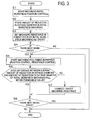
FIG. 3] FIG. 3 is a flowchart that shows process executed by a controller. - [
FIG. 4A] FIG. 4A is a graph that shows a workpiece outside diameter size, a wheel head position and a machining resistance in machining of an initial workpiece. - [
FIG. 4B] FIG. 4B is a graph that shows a workpiece outside diameter size, a wheel head position and a machining resistance in machining of a following workpiece. - Hereinafter, a specific embodiment of a machine tool and machining method according to the invention will be described with reference to the drawings. By way of example, a wheel head traverse-type external cylindrical grinding machine will be described as an example of the machine tool according to the present embodiment. Then, a shaft-like workpiece, such as a camshaft and a crankshaft, is taken as an example of a target workpiece W to be machined by the grinding machine. However, a workpiece, other than the camshaft or the crankshaft, is also applicable as the workpiece W as long as it has a shaft-like shape.
- The grinding machine will be described with reference to
FIG. 1 . As shown inFIG. 1 , the grindingmachine 1 is formed of abed 10, aheadstock 20, atailstock 30, a grindingwheel support device 40, aforce sensor 50, a sizingdevice 60 and acontroller 70. - The
bed 10 has substantially a rectangular shape and is arranged on a floor. A pair of wheelhead guide rails bed 10 so as to extend in the horizontal direction (Z-axis direction) inFIG. 1 and are parallel to each other. The pair of wheelhead guide rails head traverse base 41 that constitutes the grindingwheel support device 40 is slidable. Furthermore, on thebed 10, a wheel head Z-axis ball screw 11c is arranged between the pair of wheelhead guide rails head traverse base 41 in the horizontal direction inFIG. 1 , and a wheel head Z-axis motor 11d that drives the wheel head Z-axis ball screw 11c for rotation is arranged. - The headstock 20 (which corresponds to "supporting means" according to the invention) includes a
headstock body 21, amain spindle 22, amain spindle motor 23 and amain spindle center 24. Theheadstock body 21 is fixed to the lower left side inFIG. 1 on the upper surface of thebed 10. However, the Z-axis direction position of theheadstock body 21 is slightly adjustable with respect to thebed 10. Themain spindle 22 is inserted and supported in theheadstock body 21 so as to be rotatable about its axis (about the Z axis inFIG. 1 ). Themain spindle motor 23 is provided at the left end of themain spindle 22 inFIG. 1 . Themain spindle 22 is driven by themain spindle motor 23 for rotation with respect to theheadstock body 21. Themain spindle motor 23 has an encoder, and is able to detect the rotation angle of themain spindle motor 23 using the encoder. In addition, themain spindle center 24 that supports one axial end of the shaft-like workpiece W is connected to the right end of themain spindle 22. - The tailstock 30 (which corresponds to "supporting means" according to the invention) includes a
tailstock body 31 and atailstock spindle center 32. Thetailstock body 31 is fixed to the lower right side inFIG. 1 on the upper surface of thebed 10. However, the Z-axis direction position of thetailstock body 31 is slightly adjustable with respect to thebed 10. Thetailstock spindle center 32 is provided for thetailstock 31 so as to be non-rotatable with respect to thetailstock 31. Thetailstock spindle center 32 is located along the same axis as the rotation axis of themain spindle 22. - Then, the
tailstock spindle center 32 supports the other axial end of the workpiece W. That is, thetailstock spindle center 32 is arranged so as to face themain spindle center 24. Then, themain spindle center 24 and thetailstock spindle center 32 rotatably support both ends of the workpiece W. Furthermore, thetailstock spindle center 32 is able to change the amount of protrusion from the right end surface of thetailstock body 31. That is, the amount of protrusion of thetailstock spindle center 32 may be adjusted in response to the position of the workpiece W. In this way, the workpiece W is held by themain spindle center 24 and thetailstock spindle center 32 so as to be rotatable about the axis of the main spindle (about the Z axis). - The grinding
wheel support device 40 includes the wheelhead traverse base 41, thewheel head 42, a grinding wheel 43 (which corresponds to "tool" according to the invention) and awheel rotating motor 44. The wheelhead traverse base 41 is formed in a rectangular plate-like shape, and is arranged so as to be slidable over the pair of wheelhead guide rails bed 10. The wheelhead traverse base 41 is coupled to a nut member of the wheel head Z-axis ball screw 11c, and is driven by the wheel head Z-axis motor 11d to move along the pair of wheelhead guide rails axis motor 11d has an encoder, and is able to detect the rotation angle of the wheel head Z-axis motor 11d using the encoder. - A pair of
X-axis guide rails wheel head 42 is slidable are formed on the upper surface of the wheelhead traverse base 41 so as to extend in the vertical direction (X-axis direction) inFIG. 1 and are parallel to each other. Furthermore, on the wheelhead traverse base 41, anX-axis ball screw 41c for driving thewheel head 42 in the vertical direction ofFIG. 1 is arranged between the pair ofX-axis guide rails X-axis motor 41 d that drives theX-axis ball screw 41c for rotation is arranged. TheX-axis motor 41 d has an encoder, and is able to detect the rotation angle of theX-axis motor 41 d using the encoder. - The
wheel head 42 is arranged so as to be slidable over the pair ofX-axis guide rails head traverse base 41. Then, thewheel head 42 is coupled to a nut member of theX-axis ball screw 41c, and is driven by theX-axis motor 41d to move along the pair ofX-axis guide rails wheel head 42 is relatively movable in the X-axis direction (plunge feed direction) and the Z-axis direction (traverse feed direction) with respect to thebed 10, theheadstock 20 and thetailstock 30. - Then, a hole that extends through in the horizontal direction of
FIG. 1 is formed at the lower portion of thewheel head 42 inFIG. 1 . A grinding wheel rotary shaft member (not shown) is supported in the through hole of thewheel head 42 so as to be rotatable about the wheel central axis and parallel to the Z axis. The disc-shaped grinding wheel 43 (which corresponds to "tool" according to the invention) is coaxially connected to one end (left end inFIG. 1 ) of the grinding wheel rotary shaft member. That is, the grindingwheel 43 is supported at one end by thewheel head 42. Specifically, the right end side of thegrinding wheel 43 inFIG. 1 is supported by thewheel head 42, and the left end side of thegrinding wheel 43 inFIG. 1 is a free end. In addition, thewheel rotating motor 44 is fixed to the upper surface of thewheel head 42. Then, a pulley is suspended at the other end (right end inFIG. 1 ) of the grinding wheel rotary shaft member and the rotary shaft of thewheel rotating motor 44, so thewheel rotating motor 44 is driven to rotate thegrinding wheel 43 about the wheel spindle. - The force sensor 50 (which corresponds to "machining resistance detecting means" according to the invention) is provided for the
main spindle 22, and measures X-axis direction component force applied to themain spindle 22. That is, theforce sensor 50 detects a machining resistance that occurs as the workpiece W is machined by the grindingwheel 43. Here, in order to perform machining while moving the grindingwheel 43 only in the X direction with respect to the workpiece W, theforce sensor 50 is configured to measure only the X-axis direction component force. A signal measured by theforce sensor 50 is output to thecontroller 70. The sizing device 60 (which corresponds to "machining diameter measuring means" according to the invention) measures the outside diameter of the workpiece W at the machining position. A signal measured by the sizingdevice 60 is output to thecontroller 70. - The controller 70 (which corresponds to "control means" and "target resistance setting means" according to the invention) controls the motors to rotate the workpiece W about the main spindle, rotate the
grinding wheel 43 and change the relative position of thegrinding wheel 43 in the Z-axis direction and X-axis direction with respect to the workpiece W to thereby grind the outer peripheral surface of the workpiece W. Thecontroller 70 executes position control on the basis of the positions detected by the encoders in one case and executes resistance control on the basis of the machining resistance detected by theforce sensor 50 in the other case. The details will be described later. - Next, the function of the grinding
machine 1 and a method of machining the workpiece W using the grindingmachine 1 will be described with reference toFIG. 2 . As shown inFIG. 2 , thecontroller 70 is formed of a target machiningresistance setting unit 71 and acontrol unit 72. The target machining resistance setting unit 71 (which corresponds to "target resistance setting means" according to the invention) sets a steady target machining resistance Rt in the case where resistance control is executed. The steady target machining resistance Rt is a target machining resistance in a steady state. - Here, the steady state is a state where the amount of warpage of the workpiece W in the radial direction is constant. A state in a period from the start of machining to when the steady state is reached is called a transitional state. In the transitional state, the amount of warpage of the workpiece W in the radial direction increases. The target machining
resistance setting unit 71 initializes the steady target machining resistance Rt when an initial workpiece W is machined through position control. After that, where necessary, the target machiningresistance setting unit 71 corrects the steady target machining resistance Rt. The target machiningresistance setting unit 71 sets and corrects the steady target machining resistance Rt on the basis of information output from the encoders, the sizingdevice 60 and theforce sensor 50. - The control unit 72 (which corresponds to "control means" according to the invention) executes position control over the
motors control unit 72 executes resistance control on the basis of the target machining resistances set in the target machiningresistance setting unit 71 and information output from theforce sensor 50 to thereby machine the outer peripheral surface of the workpiece W. - Hereinafter, the process executed by the
controller 70 will be described in detail with reference toFIG. 3 ,FIG. 4A andFIG. 4B . First, the present embodiment is intended for the case where a plurality of workpieces W of the same type are successively machined. For the sake of convenience, the first workpiece W is termed initial workpiece W1, and the second and following workpieces Wn are termed following workpieces. - As shown in
FIG. 3 , first, machining the initial workpiece W1 (hereinafter, referred to as "initial workpiece machining") is started (S1). In the initial workpiece machining, position control over theX-axis motor 41 d is executed on the basis of a preset position command value and position information detected by the encoder to thereby machine the outer peripheral surface of the initial workpiece W1. That is, feedback control using the position is executed over the initial workpiece W1. Then, the feed speed of thegrinding wheel 43 in the X-axis direction is controlled through position control for the initial workpiece W1. Here, at this time point, the steady target machining resistance Rt has not been set in the target machiningresistance setting unit 71 yet. - The workpiece outside diameter size a, the wheel head position b and the machining resistance c in the initial workpiece machining behave as shown in
FIG. 4A . InFIG. 4B , T1 is a period in idle machining, T2 is a period in actual machining, T21 is a period in actual machining in the transitional state, and T22 is a period in actual machining in the steady state. - In the idle machining, the machining resistance is zero as indicated by c in
FIG. 4A . In addition, the workpiece outer size at this time is D0 as indicated by a inFIG. 4A . In addition, the behavior of the wheel head position, that is, the feed speed of thegrinding wheel 43, at this time has an inclination indicated by b inFIG. 4A . - As indicated by b in
FIG. 4A , in the actual machining after the end of the idle machining, the feed speed of thegrinding wheel 43 is the same as the feed speed during the idle machining. In the initial period in the actual machining, it is placed in the transitional state (period T21), and the machining resistance steeply increases. After that, it reaches the steady state (period T22) during which the machining resistance is constant. - Here, throughout the entire initial workpiece machining, the outside diameter reduction amount D1 of the initial workpiece W1 is stored (S2). The outside diameter reduction amount D1 of the initial workpiece W1 is measured by the sizing
device 60. Specifically, the outside diameter reduction amount D1 per unit time in the steady state in the initial workpiece machining is measured. - Subsequently, the machining resistance in the steady state (period T22) of the initial workpiece machining is set as the steady target machining resistance Rt (S3). The set steady target machining resistance Rt is stored in the target machining
resistance setting unit 71. - Subsequently, it is determined whether there is the next workpiece W (S4). Then, when there is no next workpiece W (N in S4), the process ends. On the other hand, when there is the next workpiece W, that is, the following workpiece Wn (Y in S4), machining the following workpiece Wn is started (S5). Machining of the following workpiece Wn is controlled in different ways in the case of the idle machining and in the case of the machining (actual machining). In the machining of the following workpiece Wn in the idle machining, position control over the
X-axis motor 41d is executed on the basis of position information detected by the encoder so as to coincide with the set feed speed of thegrinding wheel 43 in the idle machining. The feed speed of thegrinding wheel 43 at this time is the same as the feed speed of thegrinding wheel 43 in the idle machining of the initial workpiece machining. - The idle machining is performed in a period indicated by T1 in
FIG. 4B . The machining resistance in the idle machining is zero as indicated by C1 inFIG. 4B . In addition, the workpiece outside diameter size at this time is D0 as indicated by A inFIG. 4B . In addition, the behavior of the wheel head position, that is, the feed speed of thegrinding wheel 43, at this time has an inclination indicated by B1 inFIG. 4B . - Then, after the end of the idle machining, in machining of the following workpiece Wn in the actual machining, the
X-axis motor 41d is controlled on the basis of the machining resistance detected by theforce sensor 50 so as to reach the steady target machining resistance Rt stored in the target machiningresistance setting unit 71. That is, feedback control using the machining resistance is executed over the following workpiece Wn. Then, the feed speed of thegrinding wheel 43 in the X-axis direction is controlled through resistance control for the following workpiece Wn. - Specifically, machining in the transitional state is performed in a period indicated by T21 in
FIG. 4B . The machining resistance in the transitional state steeply increases as indicated by C2 inFIG. 4B . In the last period of the transitional state, the amount of increase in the machining resistance varies so as to gradually reduce. The workpiece outside diameter size gradually reduces as indicated by A inFIG. 4B . In addition, the behavior of the wheel head position, that is, the feed speed of thegrinding wheel 43, at this time becomes faster in the middle of the transitional state than in the initial period of the transitional state and then gradually decreases toward its last period as indicated by B2 inFIG. 4B . That is, the feed speed of thegrinding wheel 43 in the transitional state behaves so as to draw a gentle S curve. The gain of feedback control is set such that the feed speed of thegrinding wheel 43 in the transitional state behaves as described above. - Then, after the end of the transitional state, as it reaches the steady state (period T22), the machining resistance is constant as indicated by C3 in
FIG. 4B . The workpiece outer size of the steady state reduces at a constant rate as indicated by A inFIG. 4B . In addition, the behavior of the wheel head position, that is, the feed speed of thegrinding wheel 43, in the steady state is constant as indicated by B3 inFIG. 4B . - That is, resistance control is executed such that the feed speed of the
grinding wheel 43 in the transitional state is faster than the feed speed of thegrinding wheel 43 in the steady state. Furthermore, in transition from the transitional state to the steady state, resistance control is executed such that the feed speed of thegrinding wheel 43 smoothly varies. - Referring back to
FIG. 3 , description will be continued. After machining the following workpiece Wn is started (S5), first, the current outside diameter reduction amount Dn is measured. The outside diameter reduction amount Dn is measured by the sizingdevice 60. Specifically, the outside diameter reduction amount Dn per unit time in the steady state is measured. Then, the difference ΔD between the currently measured outside diameter reduction amount Dn per unit time and the outside diameter reduction amount D1 per unit time in the steady state in the initial workpiece machining (which corresponds to "target reduction amount" according to the invention) is calculated. Then, it is determined whether the difference ΔD in outside diameter reduction amount falls within a preset permissible value (S6). - Then, when the difference ΔD in outside diameter reduction amount does not fall within the permissible value (N in S6), the steady target machining resistance Rt is corrected (S7). Correcting the steady target machining resistance Rt is performed as follows. First, a value obtained by dividing the current outside diameter reduction amount Dn per unit time by the outside diameter reduction amount D1 per unit time in the initial workpiece machining is multiplied by the steady target machining resistance Rt. Then, the obtained value is set as a new steady target machining resistance Rt. The corrected steady target machining resistance Rt is set in the target machining
resistance setting unit 71 as the new steady target machining resistance Rt. - On the other hand, when the difference ΔD in outside diameter reduction amount falls within the permissible value (Y in S6) or after the steady target machining resistance is corrected in step S7, it is determined whether there is the next workpiece W (S8). Then, when there is the next workpiece W (Y in S8), the process returns to step S5 and repeats the process. On the other hand, when there is no next workpiece W (N in S8), the process ends.
- Here, in the present embodiment,
FIG. 4B shows the workpiece outer size, the wheel head position and the machining resistance in the idle machining, in the transitional state of the actual machining and in the steady state of the actual machining at the time of machining the following workpiece Wn. According to the present embodiment, the feed speed of thegrinding wheel 43 in the radial direction with respect to the workpiece W in the transitional state of the following workpiece Wn is controlled so as to be faster than the feed speed of thegrinding wheel 43 in the steady state. That is, immediately after the start of machining of the following workpiece Wn (immediately after a transition from the idle machining to the actual machining), the feed speed of thegrinding wheel 43 is controlled so as to be faster than the feed speed in the steady state to thereby make it possible to reduce the machining time of the following workpiece Wn in the transitional state. - In addition, in the present embodiment, the machining resistance in the steady state at the time when a workpiece W of the same type has been machined before is set as the steady target machining resistance Rt, and the machining resistance of the currently machining workpiece W in the transitional state is subjected to feedback control so as to reach the steady target machining resistance Rt. In this way, information at the time of the previous machining is utilized. Here, by the time when the machining resistance in the steady state is reached, it is presumable that there is no problem in terms of machining accuracy and machining burn. Thus, in the currently machining transitional state, the feed speed of the
grinding wheel 43 is controlled so as to reach the steady target machining resistance Rt to thereby make it possible to suppress occurrence of a problem of machining accuracy or machining burn. - In addition, as indicated by Q in
FIG. 4B , in the transitional state, the feed speed of thegrinding wheel 43 is controlled so as not to be constant but to be appropriately varied. As the feed speed of thegrinding wheel 43 is steeply varied in the last period of the transitional state, that is, around the point of transition from the transitional state to the steady state, there is a possibility that the actual machining resistance exceeds the steady target machining resistance Rt. Then, in some cases, there is a possibility that a problem of machining accuracy or machining burn occurs. Then, as indicated by B2 inFIG. 4B , the feed speed of thegrinding wheel 43 is controlled so as to be fast from the initial period to the middle of the transitional state, and the feed speed of thegrinding wheel 43 is controlled so as to gradually decrease around the last period of the transitional state. That is, at the time of the transition from the transitional state to the steady state, it is possible to suppress a steep variation in the feed speed of thegrinding wheel 43. As a result, it is possible to suppress occurrence of a problem of machining accuracy or machining burn. - Furthermore, in the present embodiment, the steady target machining resistance Rt is corrected on the basis of the outside diameter reduction amounts D1 and Dn of the workpieces. Here, the machining resistance varies because of a variation in sharpness of a tool (grinding wheel, or the like), or the like. In this case as well, the steady target machining resistance Rt is corrected as in the case of the present embodiment to thereby make it possible to set an appropriate steady target machining resistance Rt.
- In the above embodiment, the
control unit 72 executes resistance control over the following workpiece Wn at the time of machining. Other than the above, thecontrol unit 72 may be configured to execute position control over the following workpiece Wn not only in the idle machining but also in the actual machining. In this case, first, the wheel head position (B1, B2 and B3) that gives the behavior of the machining resistance (C1, C2 and C3) ofFIG. 4B is calculated on the basis of information obtained at the time of machining the initial workpiece W1. The calculated wheel head position becomes a command value in position control. Then, thecontrol unit 72 executes position control over theX-axis motor 41 d so as to be positioned at the calculated wheel head position (Bl, B2 and B3). That is, the feed speed of thegrinding wheel 43 is directly controlled. - Thus, the
control unit 72 controls the feed speed of thegrinding wheel 43 in the transitional state so as to be faster than the feed speed of thegrinding wheel 43 in the steady state. By so doing, in the present embodiment as well, it is possible to reduce the machining time as in the case of the above described embodiment. - In addition, in this case, when the above position control is executed with a decrease in sharpness of the
grinding wheel 43, the machining resistance may decrease. In such a case, it is only necessary that the wheel head position is corrected such that the machining resistance in the steady state is detected by theforce sensor 50 during machining of the following workpiece Wn and is brought into coincidence with the machining resistance of the initial workpiece W1 in the steady state. By so doing, even when the machining resistance is decreased, it is possible to appropriately perform machining with a desired machining resistance. That is, it is possible to reliably reduce the machining time. - Note that the
force sensor 50 may be provided for thetailstock spindle center 32 instead of themain spindle 22, and a strain gauge may be attached to thetailstock spindle center 32 to thereby detect the machining resistance as the amount of strain of thetailstock spindle center 32. In addition, theforce sensor 50 may be provided for both themain spindle 22 and thetailstock spindle center 32. In addition, instead of theforce sensor 50, the power of thewheel rotating motor 44 is detected on the basis of a variation in current flowing through thewheel rotating motor 44 to thereby make it possible to detect the machining resistance that occurs as a workpiece W is machined by the grindingwheel 43 with that power. - In addition, the power of the
X-axis motor 41d is detected on the basis of a variation in current flowing through theX-axis motor 41 d that drives thewheel head 42 to thereby make it possible to detect the machining resistance that occurs as a workpiece W is machined by the grindingwheel 43 with that power. Note that, in this case, it is desirable that thewheel head 42 is driven not by theX-axis motor 41d, which is a rotary motor, and theball screw 41c but by a linear motor because it is possible to further accurately detect the machining resistance. - In addition, machining in the above described embodiment may be applied to rough machining; instead, it may also be applied to finish machining. In addition, in the above embodiment, the case where the outer peripheral surface of the workpiece W is machined in the radial direction is described as an example; however, other than this, it may be similarly applied to the case where the inner peripheral surface is machined in the radial direction.
Claims (7)
- A machine tool (1) comprising:supporting means (20, 30) that rotatably supports a shaft-like workpiece (W);a tool (43) that is relatively movable in a radial direction of the workpiece (W) with respect to the supporting means (20, 30); andcontrol means (70, 72) that relatively moves the supporting means (20, 30) and the tool (43) to machine a peripheral surface of the workpiece (W) in the radial direction, characterized in thatthe control means (70, 72) executes control such that a relative feed speed of the tool (43) in the radial direction in a transitional state where an amount of warpage of the workpiece (W) in the radial direction at a machining position increases is faster than a relative feed speed of the tool (43) in the radial direction in a steady state where an amount of warpage of the workpiece (W) in the radial direction at the machining position is constant.
- The machine tool (1) according to claim 1, wherein
the transitional state is a state immediately after a transition from idle machining to machining. - The machine tool (1) according to claim 1 or 2, further comprising:machining resistance detecting means (50) that detects a machining resistance that occurs at the time when the workpiece (W) is machined by the tool (43) in actual machining; andtarget machining resistance setting means (70, 71) that, when the workpiece (W) of the same type has been machined before, sets the machining resistance in a steady state where the amount of warpage of the workpiece (W) in the radial direction is constant as a steady target machining resistance, whereinin the transitional state, the control means (70, 72) controls the feed speed of the tool (43) in the radial direction such that the current machining resistance reaches the target machining resistance.
- The machine tool (1) according to claim 3, wherein
the control means (70, 72) varies the feed speed of the tool (43) in the radial direction in response to the current machining resistance in the transitional state. - The machine tool (1) according to claim 3 or 4, further comprising:machining diameter measuring means (60) that measures a machining diameter of the workpiece (W), whereinat the time of machining the workpiece (W), the target machining resistance setting means (70, 71) corrects the steady target machining resistance on the basis of the machining diameter of the workpiece, measured by the machining diameter measuring means (60).
- The machine tool (1) according to claim 5, wherein
when the steady target machining resistance is set, the target machining resistance setting means (70, 71) sets an amount of reduction per unit time of the machining diameter of the workpiece (W) in the steady state, calculated by the machining diameter measuring means (60) in advance,
when the current workpiece (W) is machined, the target machining resistance setting means (70, 71) uses the machining diameter measuring means (60) to calculate a current amount of reduction per unit time of the machining diameter of the workpiece (W) in the steady state,
the target machining resistance setting means (70, 71) multiplies a value, obtained by dividing the current amount of reduction per unit time of the machining diameter by the set amount of reduction per unit time of the machining diameter, by the steady target machining resistance, and
the target machining resistance setting means (70, 71) sets the obtained value as the new steady target machining resistance. - A machining method for relatively moving a shaft-like workpiece (W) and a tool (43) in a radial direction of the workpiece (W) while rotating the workpiece (W) to thereby machine a peripheral surface of the workpiece (W) in the radial direction, characterized by comprising:executing control such that a relative feed speed of the tool (43) in the radial direction in a transitional state where an amount of warpage of the workpiece (W) in the radial direction at a machining position increases is faster than a relative feed speed of the tool (43) in the radial direction in a steady state where an amount of warpage of the workpiece (W) in the radial direction at the machining position is constant.
Applications Claiming Priority (2)
| Application Number | Priority Date | Filing Date | Title |
|---|---|---|---|
| JP2009210113A JP5353586B2 (en) | 2009-09-11 | 2009-09-11 | Machine tool and processing method |
| PCT/JP2010/065651 WO2011030866A1 (en) | 2009-09-11 | 2010-09-10 | Machine tool and machining method |
Publications (3)
| Publication Number | Publication Date |
|---|---|
| EP2476513A1 EP2476513A1 (en) | 2012-07-18 |
| EP2476513A4 EP2476513A4 (en) | 2014-09-03 |
| EP2476513B1 true EP2476513B1 (en) | 2016-08-17 |
Family
ID=43732534
Family Applications (1)
| Application Number | Title | Priority Date | Filing Date |
|---|---|---|---|
| EP10815460.0A Not-in-force EP2476513B1 (en) | 2009-09-11 | 2010-09-10 | Machine tool and machining method |
Country Status (5)
| Country | Link |
|---|---|
| US (1) | US8900034B2 (en) |
| EP (1) | EP2476513B1 (en) |
| JP (1) | JP5353586B2 (en) |
| CN (1) | CN102481680B (en) |
| WO (1) | WO2011030866A1 (en) |
Families Citing this family (10)
| Publication number | Priority date | Publication date | Assignee | Title |
|---|---|---|---|---|
| JP5423313B2 (en) * | 2009-10-26 | 2014-02-19 | 株式会社ジェイテクト | Grinding machine and grinding method |
| JP5418148B2 (en) * | 2009-10-28 | 2014-02-19 | 株式会社ジェイテクト | Grinding machine and grinding method |
| JP5708324B2 (en) * | 2011-07-11 | 2015-04-30 | 日本精工株式会社 | Grinding machine and grinding method |
| JP6102480B2 (en) * | 2013-05-08 | 2017-03-29 | 株式会社ジェイテクト | Grinding machine and grinding method |
| EP3115149B1 (en) * | 2015-07-08 | 2018-03-14 | Scania CV AB | Method of grinding a workpiece having a cylindrical bearing surface and method for determining processing parameters |
| CN106514441A (en) * | 2015-12-04 | 2017-03-22 | 重庆江陆激光科技有限公司 | Wiredrawing polishing tool |
| JP6972555B2 (en) * | 2017-01-06 | 2021-11-24 | 株式会社ジェイテクト | Grinding equipment and grinding method |
| WO2018131399A1 (en) * | 2017-01-10 | 2018-07-19 | ミクロン精密株式会社 | Grinding apparatus and grinding method |
| CN114888648A (en) * | 2022-07-08 | 2022-08-12 | 游隼信息技术科技(苏州)有限公司 | Shaft grinding processing equipment |
| CN115805506A (en) * | 2023-02-09 | 2023-03-17 | 太原市三高能源发展有限公司 | Polishing device for casting of mechanical parts and using method |
Family Cites Families (21)
| Publication number | Priority date | Publication date | Assignee | Title |
|---|---|---|---|---|
| US2802312A (en) * | 1953-11-13 | 1957-08-13 | Cincinnati Milling Machine Co | Grinding machine |
| US2984952A (en) * | 1958-04-29 | 1961-05-23 | Landis Tool Co | Pressure operated feed control for grinding machines |
| US3247620A (en) * | 1963-11-15 | 1966-04-26 | Landis Tool Co | Multiple position feed mechanism |
| JPS4840860B1 (en) * | 1970-08-28 | 1973-12-03 | ||
| IT959396B (en) * | 1972-06-06 | 1973-11-10 | Finike Italiana Marposs | DEVICE FOR CONTROL OF THE APPROACH SPEED IN MACHINE TOOLS IN PARTICULAR GRINDING MACHINES |
| JPS5712663B2 (en) | 1973-10-29 | 1982-03-12 | ||
| US4118900A (en) | 1976-03-29 | 1978-10-10 | Seiko Seiki Kabushiki Kaisha | Method for controlling grinding process |
| US4187646A (en) | 1976-08-16 | 1980-02-12 | The Valeron Corporation | Apparatus for grinding |
| JP3293300B2 (en) | 1994-01-31 | 2002-06-17 | 豊田工機株式会社 | Grinding equipment |
| JPH08168957A (en) * | 1994-09-30 | 1996-07-02 | Toyoda Mach Works Ltd | Grinding device |
| JP3490534B2 (en) * | 1995-03-23 | 2004-01-26 | オークマ株式会社 | Non-circular workpiece grinding method and apparatus |
| JP3589546B2 (en) * | 1997-04-08 | 2004-11-17 | 富士通株式会社 | Automatic wrapping method and apparatus |
| JP2000263437A (en) * | 1999-03-16 | 2000-09-26 | Mitsubishi Heavy Ind Ltd | Cylindrical grinding wheel |
| JP2002292560A (en) | 2001-03-29 | 2002-10-08 | Toyo Advanced Technologies Co Ltd | Grinding method and device therefor |
| DE10149175A1 (en) * | 2001-10-04 | 2003-04-17 | Heidenhain Gmbh Dr Johannes | Tracking control for machine tool, includes program segment for velocity control applied separately to linear- and angular axes |
| JP2003275957A (en) * | 2002-03-25 | 2003-09-30 | Toyo Advanced Technologies Co Ltd | Grinding method and device |
| JP2004114195A (en) | 2002-09-25 | 2004-04-15 | Toyoda Mach Works Ltd | Grinding method and cylindrical grinding machine |
| DE602004006654T2 (en) * | 2003-02-12 | 2008-02-07 | Nissan Motor Co., Ltd., Yokohama | Apparatus and method for surface finishing |
| JP4858456B2 (en) | 2008-01-29 | 2012-01-18 | トヨタ自動車株式会社 | Camshaft manufacturing method |
| CN101259554A (en) * | 2008-04-24 | 2008-09-10 | 上海交通大学 | Fine electrospark electrode wear fixed length compensation process |
| US8517797B2 (en) | 2009-10-28 | 2013-08-27 | Jtekt Corporation | Grinding machine and grinding method |
-
2009
- 2009-09-11 JP JP2009210113A patent/JP5353586B2/en not_active Expired - Fee Related
-
2010
- 2010-09-10 EP EP10815460.0A patent/EP2476513B1/en not_active Not-in-force
- 2010-09-10 US US13/394,352 patent/US8900034B2/en not_active Expired - Fee Related
- 2010-09-10 WO PCT/JP2010/065651 patent/WO2011030866A1/en active Application Filing
- 2010-09-10 CN CN201080040217.5A patent/CN102481680B/en not_active Expired - Fee Related
Also Published As
| Publication number | Publication date |
|---|---|
| US20120164920A1 (en) | 2012-06-28 |
| WO2011030866A1 (en) | 2011-03-17 |
| EP2476513A1 (en) | 2012-07-18 |
| JP5353586B2 (en) | 2013-11-27 |
| CN102481680A (en) | 2012-05-30 |
| JP2011056629A (en) | 2011-03-24 |
| US8900034B2 (en) | 2014-12-02 |
| CN102481680B (en) | 2014-08-20 |
| EP2476513A4 (en) | 2014-09-03 |
Similar Documents
| Publication | Publication Date | Title |
|---|---|---|
| EP2476513B1 (en) | Machine tool and machining method | |
| US8299743B2 (en) | Machine tool and controlling method thereof | |
| EP2457689B1 (en) | Method and device for preventing slip of work piece | |
| EP2214070B1 (en) | Machine tool with workpiece size measurement | |
| JP6102480B2 (en) | Grinding machine and grinding method | |
| JP5402347B2 (en) | Work slip prevention method and apparatus | |
| JP5218103B2 (en) | Machine Tools | |
| US9174318B2 (en) | Machine tool and control method for the same | |
| JP2005262326A (en) | Tailstock | |
| JP5029046B2 (en) | Processing equipment | |
| JP2011104675A (en) | Grinding machine and grinding method | |
| JP5515480B2 (en) | Center pressure automatic control device | |
| JP2602965B2 (en) | Automatic cylindrical grinding machine | |
| JPH06226534A (en) | Gear honing method and device | |
| JP5266020B2 (en) | Machine tool and error correction method in machine tool | |
| JP7322603B2 (en) | Machine Tools | |
| JP2940435B2 (en) | Adjustment method of retraction amount in grinding | |
| JP2022046298A (en) | Grinder and grinding method | |
| JP5332658B2 (en) | Machine Tools | |
| JPH06278021A (en) | Grinding device | |
| JPH06126530A (en) | Gear honing-machining device | |
| JP2001260019A (en) | Grinding device and grinding method | |
| JPH06304863A (en) | Grinding device | |
| JPH06114723A (en) | Polishing device for hole internal surface |
Legal Events
| Date | Code | Title | Description |
|---|---|---|---|
| PUAI | Public reference made under article 153(3) epc to a published international application that has entered the european phase |
Free format text: ORIGINAL CODE: 0009012 |
|
| 17P | Request for examination filed |
Effective date: 20120305 |
|
| AK | Designated contracting states |
Kind code of ref document: A1 Designated state(s): AL AT BE BG CH CY CZ DE DK EE ES FI FR GB GR HR HU IE IS IT LI LT LU LV MC MK MT NL NO PL PT RO SE SI SK SM TR |
|
| DAX | Request for extension of the european patent (deleted) | ||
| A4 | Supplementary search report drawn up and despatched |
Effective date: 20140805 |
|
| RIC1 | Information provided on ipc code assigned before grant |
Ipc: B24B 47/20 20060101AFI20140730BHEP Ipc: B24B 5/42 20060101ALI20140730BHEP Ipc: B24B 49/16 20060101ALI20140730BHEP Ipc: B24B 5/04 20060101ALI20140730BHEP Ipc: B24B 49/04 20060101ALI20140730BHEP Ipc: B24B 19/12 20060101ALI20140730BHEP Ipc: B24B 49/00 20120101ALI20140730BHEP |
|
| RIC1 | Information provided on ipc code assigned before grant |
Ipc: B24B 49/00 20120101ALI20160303BHEP Ipc: B24B 5/42 20060101ALI20160303BHEP Ipc: B24B 49/04 20060101ALI20160303BHEP Ipc: B24B 49/16 20060101ALI20160303BHEP Ipc: B24B 47/20 20060101AFI20160303BHEP Ipc: B24B 5/04 20060101ALI20160303BHEP Ipc: B24B 19/12 20060101ALI20160303BHEP |
|
| GRAP | Despatch of communication of intention to grant a patent |
Free format text: ORIGINAL CODE: EPIDOSNIGR1 |
|
| INTG | Intention to grant announced |
Effective date: 20160419 |
|
| GRAS | Grant fee paid |
Free format text: ORIGINAL CODE: EPIDOSNIGR3 |
|
| GRAA | (expected) grant |
Free format text: ORIGINAL CODE: 0009210 |
|
| AK | Designated contracting states |
Kind code of ref document: B1 Designated state(s): AL AT BE BG CH CY CZ DE DK EE ES FI FR GB GR HR HU IE IS IT LI LT LU LV MC MK MT NL NO PL PT RO SE SI SK SM TR |
|
| REG | Reference to a national code |
Ref country code: GB Ref legal event code: FG4D |
|
| REG | Reference to a national code |
Ref country code: CH Ref legal event code: EP |
|
| REG | Reference to a national code |
Ref country code: IE Ref legal event code: FG4D |
|
| REG | Reference to a national code |
Ref country code: AT Ref legal event code: REF Ref document number: 820601 Country of ref document: AT Kind code of ref document: T Effective date: 20160915 |
|
| REG | Reference to a national code |
Ref country code: DE Ref legal event code: R096 Ref document number: 602010035691 Country of ref document: DE |
|
| REG | Reference to a national code |
Ref country code: NL Ref legal event code: MP Effective date: 20160817 |
|
| REG | Reference to a national code |
Ref country code: LT Ref legal event code: MG4D |
|
| REG | Reference to a national code |
Ref country code: AT Ref legal event code: MK05 Ref document number: 820601 Country of ref document: AT Kind code of ref document: T Effective date: 20160817 |
|
| PG25 | Lapsed in a contracting state [announced via postgrant information from national office to epo] |
Ref country code: IT Free format text: LAPSE BECAUSE OF FAILURE TO SUBMIT A TRANSLATION OF THE DESCRIPTION OR TO PAY THE FEE WITHIN THE PRESCRIBED TIME-LIMIT Effective date: 20160817 Ref country code: LT Free format text: LAPSE BECAUSE OF FAILURE TO SUBMIT A TRANSLATION OF THE DESCRIPTION OR TO PAY THE FEE WITHIN THE PRESCRIBED TIME-LIMIT Effective date: 20160817 Ref country code: NO Free format text: LAPSE BECAUSE OF FAILURE TO SUBMIT A TRANSLATION OF THE DESCRIPTION OR TO PAY THE FEE WITHIN THE PRESCRIBED TIME-LIMIT Effective date: 20161117 Ref country code: HR Free format text: LAPSE BECAUSE OF FAILURE TO SUBMIT A TRANSLATION OF THE DESCRIPTION OR TO PAY THE FEE WITHIN THE PRESCRIBED TIME-LIMIT Effective date: 20160817 Ref country code: NL Free format text: LAPSE BECAUSE OF FAILURE TO SUBMIT A TRANSLATION OF THE DESCRIPTION OR TO PAY THE FEE WITHIN THE PRESCRIBED TIME-LIMIT Effective date: 20160817 Ref country code: FI Free format text: LAPSE BECAUSE OF FAILURE TO SUBMIT A TRANSLATION OF THE DESCRIPTION OR TO PAY THE FEE WITHIN THE PRESCRIBED TIME-LIMIT Effective date: 20160817 |
|
| PG25 | Lapsed in a contracting state [announced via postgrant information from national office to epo] |
Ref country code: ES Free format text: LAPSE BECAUSE OF FAILURE TO SUBMIT A TRANSLATION OF THE DESCRIPTION OR TO PAY THE FEE WITHIN THE PRESCRIBED TIME-LIMIT Effective date: 20160817 Ref country code: PL Free format text: LAPSE BECAUSE OF FAILURE TO SUBMIT A TRANSLATION OF THE DESCRIPTION OR TO PAY THE FEE WITHIN THE PRESCRIBED TIME-LIMIT Effective date: 20160817 Ref country code: BE Free format text: LAPSE BECAUSE OF NON-PAYMENT OF DUE FEES Effective date: 20160930 Ref country code: SE Free format text: LAPSE BECAUSE OF FAILURE TO SUBMIT A TRANSLATION OF THE DESCRIPTION OR TO PAY THE FEE WITHIN THE PRESCRIBED TIME-LIMIT Effective date: 20160817 Ref country code: GR Free format text: LAPSE BECAUSE OF FAILURE TO SUBMIT A TRANSLATION OF THE DESCRIPTION OR TO PAY THE FEE WITHIN THE PRESCRIBED TIME-LIMIT Effective date: 20161118 Ref country code: LV Free format text: LAPSE BECAUSE OF FAILURE TO SUBMIT A TRANSLATION OF THE DESCRIPTION OR TO PAY THE FEE WITHIN THE PRESCRIBED TIME-LIMIT Effective date: 20160817 Ref country code: AT Free format text: LAPSE BECAUSE OF FAILURE TO SUBMIT A TRANSLATION OF THE DESCRIPTION OR TO PAY THE FEE WITHIN THE PRESCRIBED TIME-LIMIT Effective date: 20160817 Ref country code: PT Free format text: LAPSE BECAUSE OF FAILURE TO SUBMIT A TRANSLATION OF THE DESCRIPTION OR TO PAY THE FEE WITHIN THE PRESCRIBED TIME-LIMIT Effective date: 20161219 |
|
| PG25 | Lapsed in a contracting state [announced via postgrant information from national office to epo] |
Ref country code: RO Free format text: LAPSE BECAUSE OF FAILURE TO SUBMIT A TRANSLATION OF THE DESCRIPTION OR TO PAY THE FEE WITHIN THE PRESCRIBED TIME-LIMIT Effective date: 20160817 Ref country code: EE Free format text: LAPSE BECAUSE OF FAILURE TO SUBMIT A TRANSLATION OF THE DESCRIPTION OR TO PAY THE FEE WITHIN THE PRESCRIBED TIME-LIMIT Effective date: 20160817 |
|
| REG | Reference to a national code |
Ref country code: CH Ref legal event code: PL |
|
| REG | Reference to a national code |
Ref country code: DE Ref legal event code: R097 Ref document number: 602010035691 Country of ref document: DE |
|
| PG25 | Lapsed in a contracting state [announced via postgrant information from national office to epo] |
Ref country code: DK Free format text: LAPSE BECAUSE OF FAILURE TO SUBMIT A TRANSLATION OF THE DESCRIPTION OR TO PAY THE FEE WITHIN THE PRESCRIBED TIME-LIMIT Effective date: 20160817 Ref country code: CZ Free format text: LAPSE BECAUSE OF FAILURE TO SUBMIT A TRANSLATION OF THE DESCRIPTION OR TO PAY THE FEE WITHIN THE PRESCRIBED TIME-LIMIT Effective date: 20160817 Ref country code: SM Free format text: LAPSE BECAUSE OF FAILURE TO SUBMIT A TRANSLATION OF THE DESCRIPTION OR TO PAY THE FEE WITHIN THE PRESCRIBED TIME-LIMIT Effective date: 20160817 Ref country code: BG Free format text: LAPSE BECAUSE OF FAILURE TO SUBMIT A TRANSLATION OF THE DESCRIPTION OR TO PAY THE FEE WITHIN THE PRESCRIBED TIME-LIMIT Effective date: 20161117 Ref country code: BE Free format text: LAPSE BECAUSE OF FAILURE TO SUBMIT A TRANSLATION OF THE DESCRIPTION OR TO PAY THE FEE WITHIN THE PRESCRIBED TIME-LIMIT Effective date: 20160817 Ref country code: SK Free format text: LAPSE BECAUSE OF FAILURE TO SUBMIT A TRANSLATION OF THE DESCRIPTION OR TO PAY THE FEE WITHIN THE PRESCRIBED TIME-LIMIT Effective date: 20160817 |
|
| PLBE | No opposition filed within time limit |
Free format text: ORIGINAL CODE: 0009261 |
|
| STAA | Information on the status of an ep patent application or granted ep patent |
Free format text: STATUS: NO OPPOSITION FILED WITHIN TIME LIMIT |
|
| REG | Reference to a national code |
Ref country code: IE Ref legal event code: MM4A |
|
| PG25 | Lapsed in a contracting state [announced via postgrant information from national office to epo] |
Ref country code: MC Free format text: LAPSE BECAUSE OF FAILURE TO SUBMIT A TRANSLATION OF THE DESCRIPTION OR TO PAY THE FEE WITHIN THE PRESCRIBED TIME-LIMIT Effective date: 20160817 |
|
| REG | Reference to a national code |
Ref country code: FR Ref legal event code: ST Effective date: 20170531 |
|
| 26N | No opposition filed |
Effective date: 20170518 |
|
| GBPC | Gb: european patent ceased through non-payment of renewal fee |
Effective date: 20161117 |
|
| PG25 | Lapsed in a contracting state [announced via postgrant information from national office to epo] |
Ref country code: FR Free format text: LAPSE BECAUSE OF NON-PAYMENT OF DUE FEES Effective date: 20161017 Ref country code: IE Free format text: LAPSE BECAUSE OF NON-PAYMENT OF DUE FEES Effective date: 20160910 Ref country code: LI Free format text: LAPSE BECAUSE OF NON-PAYMENT OF DUE FEES Effective date: 20160930 Ref country code: CH Free format text: LAPSE BECAUSE OF NON-PAYMENT OF DUE FEES Effective date: 20160930 |
|
| PG25 | Lapsed in a contracting state [announced via postgrant information from national office to epo] |
Ref country code: LU Free format text: LAPSE BECAUSE OF NON-PAYMENT OF DUE FEES Effective date: 20160910 Ref country code: SI Free format text: LAPSE BECAUSE OF FAILURE TO SUBMIT A TRANSLATION OF THE DESCRIPTION OR TO PAY THE FEE WITHIN THE PRESCRIBED TIME-LIMIT Effective date: 20160817 |
|
| PG25 | Lapsed in a contracting state [announced via postgrant information from national office to epo] |
Ref country code: GB Free format text: LAPSE BECAUSE OF NON-PAYMENT OF DUE FEES Effective date: 20161117 |
|
| PG25 | Lapsed in a contracting state [announced via postgrant information from national office to epo] |
Ref country code: HU Free format text: LAPSE BECAUSE OF FAILURE TO SUBMIT A TRANSLATION OF THE DESCRIPTION OR TO PAY THE FEE WITHIN THE PRESCRIBED TIME-LIMIT; INVALID AB INITIO Effective date: 20100910 Ref country code: CY Free format text: LAPSE BECAUSE OF FAILURE TO SUBMIT A TRANSLATION OF THE DESCRIPTION OR TO PAY THE FEE WITHIN THE PRESCRIBED TIME-LIMIT Effective date: 20160817 |
|
| PG25 | Lapsed in a contracting state [announced via postgrant information from national office to epo] |
Ref country code: TR Free format text: LAPSE BECAUSE OF FAILURE TO SUBMIT A TRANSLATION OF THE DESCRIPTION OR TO PAY THE FEE WITHIN THE PRESCRIBED TIME-LIMIT Effective date: 20160817 Ref country code: MK Free format text: LAPSE BECAUSE OF FAILURE TO SUBMIT A TRANSLATION OF THE DESCRIPTION OR TO PAY THE FEE WITHIN THE PRESCRIBED TIME-LIMIT Effective date: 20160817 Ref country code: MT Free format text: LAPSE BECAUSE OF NON-PAYMENT OF DUE FEES Effective date: 20160930 Ref country code: IS Free format text: LAPSE BECAUSE OF FAILURE TO SUBMIT A TRANSLATION OF THE DESCRIPTION OR TO PAY THE FEE WITHIN THE PRESCRIBED TIME-LIMIT Effective date: 20160817 |
|
| PG25 | Lapsed in a contracting state [announced via postgrant information from national office to epo] |
Ref country code: AL Free format text: LAPSE BECAUSE OF FAILURE TO SUBMIT A TRANSLATION OF THE DESCRIPTION OR TO PAY THE FEE WITHIN THE PRESCRIBED TIME-LIMIT Effective date: 20160817 |
|
| PGFP | Annual fee paid to national office [announced via postgrant information from national office to epo] |
Ref country code: DE Payment date: 20200826 Year of fee payment: 11 |
|
| REG | Reference to a national code |
Ref country code: DE Ref legal event code: R119 Ref document number: 602010035691 Country of ref document: DE |
|
| PG25 | Lapsed in a contracting state [announced via postgrant information from national office to epo] |
Ref country code: DE Free format text: LAPSE BECAUSE OF NON-PAYMENT OF DUE FEES Effective date: 20220401 |