EP2476504A1 - Processing device - Google Patents
Processing device Download PDFInfo
- Publication number
- EP2476504A1 EP2476504A1 EP20110196018 EP11196018A EP2476504A1 EP 2476504 A1 EP2476504 A1 EP 2476504A1 EP 20110196018 EP20110196018 EP 20110196018 EP 11196018 A EP11196018 A EP 11196018A EP 2476504 A1 EP2476504 A1 EP 2476504A1
- Authority
- EP
- European Patent Office
- Prior art keywords
- shaft
- radiation
- unit
- cavity
- processing
- Prior art date
- Legal status (The legal status is an assumption and is not a legal conclusion. Google has not performed a legal analysis and makes no representation as to the accuracy of the status listed.)
- Granted
Links
- 230000005855 radiation Effects 0.000 claims abstract description 61
- 238000003754 machining Methods 0.000 claims abstract description 9
- 239000011248 coating agent Substances 0.000 claims description 20
- 238000000576 coating method Methods 0.000 claims description 20
- 239000000463 material Substances 0.000 claims description 19
- 230000005540 biological transmission Effects 0.000 claims description 6
- 239000002023 wood Substances 0.000 claims description 4
- 230000003287 optical effect Effects 0.000 claims description 3
- 239000004033 plastic Substances 0.000 claims description 2
- 229920003023 plastic Polymers 0.000 claims description 2
- 239000004020 conductor Substances 0.000 claims 1
- 230000001678 irradiating effect Effects 0.000 abstract 1
- 238000004026 adhesive bonding Methods 0.000 description 14
- 230000004048 modification Effects 0.000 description 4
- 238000012986 modification Methods 0.000 description 4
- 238000005304 joining Methods 0.000 description 2
- 238000004519 manufacturing process Methods 0.000 description 2
- 238000004513 sizing Methods 0.000 description 2
- 230000006978 adaptation Effects 0.000 description 1
- 230000008901 benefit Effects 0.000 description 1
- 230000008859 change Effects 0.000 description 1
- 230000008878 coupling Effects 0.000 description 1
- 238000010168 coupling process Methods 0.000 description 1
- 238000005859 coupling reaction Methods 0.000 description 1
- 230000001419 dependent effect Effects 0.000 description 1
- 238000005516 engineering process Methods 0.000 description 1
- 239000003292 glue Substances 0.000 description 1
- 238000009434 installation Methods 0.000 description 1
- 230000010354 integration Effects 0.000 description 1
- 230000003993 interaction Effects 0.000 description 1
- 238000002372 labelling Methods 0.000 description 1
- 239000002184 metal Substances 0.000 description 1
- 229910052751 metal Inorganic materials 0.000 description 1
- 150000002739 metals Chemical class 0.000 description 1
- 238000010248 power generation Methods 0.000 description 1
- 238000003860 storage Methods 0.000 description 1
Images


Classifications
-
- B—PERFORMING OPERATIONS; TRANSPORTING
- B23—MACHINE TOOLS; METAL-WORKING NOT OTHERWISE PROVIDED FOR
- B23K—SOLDERING OR UNSOLDERING; WELDING; CLADDING OR PLATING BY SOLDERING OR WELDING; CUTTING BY APPLYING HEAT LOCALLY, e.g. FLAME CUTTING; WORKING BY LASER BEAM
- B23K26/00—Working by laser beam, e.g. welding, cutting or boring
- B23K26/0093—Working by laser beam, e.g. welding, cutting or boring combined with mechanical machining or metal-working covered by other subclasses than B23K
-
- B—PERFORMING OPERATIONS; TRANSPORTING
- B23—MACHINE TOOLS; METAL-WORKING NOT OTHERWISE PROVIDED FOR
- B23K—SOLDERING OR UNSOLDERING; WELDING; CLADDING OR PLATING BY SOLDERING OR WELDING; CUTTING BY APPLYING HEAT LOCALLY, e.g. FLAME CUTTING; WORKING BY LASER BEAM
- B23K26/00—Working by laser beam, e.g. welding, cutting or boring
- B23K26/14—Working by laser beam, e.g. welding, cutting or boring using a fluid stream, e.g. a jet of gas, in conjunction with the laser beam; Nozzles therefor
- B23K26/1462—Nozzles; Features related to nozzles
- B23K26/1482—Detachable nozzles, e.g. exchangeable or provided with breakaway lines
-
- B—PERFORMING OPERATIONS; TRANSPORTING
- B23—MACHINE TOOLS; METAL-WORKING NOT OTHERWISE PROVIDED FOR
- B23K—SOLDERING OR UNSOLDERING; WELDING; CLADDING OR PLATING BY SOLDERING OR WELDING; CUTTING BY APPLYING HEAT LOCALLY, e.g. FLAME CUTTING; WORKING BY LASER BEAM
- B23K26/00—Working by laser beam, e.g. welding, cutting or boring
- B23K26/20—Bonding
- B23K26/32—Bonding taking account of the properties of the material involved
- B23K26/324—Bonding taking account of the properties of the material involved involving non-metallic parts
-
- B—PERFORMING OPERATIONS; TRANSPORTING
- B23—MACHINE TOOLS; METAL-WORKING NOT OTHERWISE PROVIDED FOR
- B23K—SOLDERING OR UNSOLDERING; WELDING; CLADDING OR PLATING BY SOLDERING OR WELDING; CUTTING BY APPLYING HEAT LOCALLY, e.g. FLAME CUTTING; WORKING BY LASER BEAM
- B23K26/00—Working by laser beam, e.g. welding, cutting or boring
- B23K26/34—Laser welding for purposes other than joining
-
- B—PERFORMING OPERATIONS; TRANSPORTING
- B27—WORKING OR PRESERVING WOOD OR SIMILAR MATERIAL; NAILING OR STAPLING MACHINES IN GENERAL
- B27D—WORKING VENEER OR PLYWOOD
- B27D5/00—Other working of veneer or plywood specially adapted to veneer or plywood
- B27D5/003—Other working of veneer or plywood specially adapted to veneer or plywood securing a veneer strip to a panel edge
-
- B—PERFORMING OPERATIONS; TRANSPORTING
- B23—MACHINE TOOLS; METAL-WORKING NOT OTHERWISE PROVIDED FOR
- B23K—SOLDERING OR UNSOLDERING; WELDING; CLADDING OR PLATING BY SOLDERING OR WELDING; CUTTING BY APPLYING HEAT LOCALLY, e.g. FLAME CUTTING; WORKING BY LASER BEAM
- B23K2103/00—Materials to be soldered, welded or cut
- B23K2103/30—Organic material
Definitions
- the present invention relates to a
- Generic processing devices are used for example in the machining of workpieces, which are at least partially constructed of wood, wood materials, plastics, metals (such as fittings) or a combination thereof, e.g. in the furniture and component industry.
- Radiation in particular laser radiation, is increasingly used in various manufacturing processes, e.g. when separating, joining or labeling.
- the heat generated by the radiation is used selectively to perform appropriate steps.
- the present invention has for its object to provide a processing device with a beam guiding device, in which the beam guiding device is integrated as possible in the machine without affecting the functionality of the machine.
- the invention is based on the idea of a beam guiding device within a To provide processing machine such that thereby no significant modifications or redesigns are required. Accordingly, to a processing machine, with a common processing, such as a machining, can be performed via an interface energy input provided, the forwarding of energy, in particular the radiant energy within the device sections through a cavity of a shaft and / or a cavity extends within an aggregate connected to the shaft.
- radiation in the context of this application is to be interpreted broadly. For example only, a laser radiation is mentioned in this application. However, microwave radiation, W radiation, infrared radiation, heat radiation, etc. are also included. Accordingly, “radiation” in the context of this application is to be understood as energy transmission from a generator source to a processing zone.
- a device comprising: a radiation device for generating and / or transmitting radiation, preferably a laser beam, and a spindle unit with a rotatable in a shaft bearing portion shaft and a receptacle for processing tools and / or processing units.
- the novel device is characterized in that the shaft and / or the shaft bearing section at least partially have a cavity, and the radiation device is arranged such that the radiation extends at least partially within the cavity.
- the cavity that opens in sections in the shaft and / or the Shaft bearing section runs, in the area of recording for machining tools and / or processing units, or in an aggregate connected to the shaft.
- the latter can be formed for example as a chuck.
- the cavity extends in the axial direction of the shaft through the entire shaft.
- the wave itself can be used as a conduit section for the radiation.
- provision may be made for the cavity to extend through a tensioning means extending through the shaft.
- a tensioning means may be, for example, a pull rod with which, for example, a chuck can be releasably attached to the shaft. In this way, the transmission of radiation within the device according to the invention is integrated particularly favorably.
- the spindle unit can be moved in at least one, preferably in three, different directions. Alternatively or additionally the spindle unit can be pivoted about at least one axis. Particularly preferred is the configuration of the spindle unit as a 5-axis unit (at least three translational and 2 rotary axes).
- the radiation device can be directly or indirectly connected to the spindle unit, or even be moved with this. If the radiation device is connected indirectly to the spindle unit, then it can be provided that the radiation device operates a plurality of devices with radiation.
- a processing unit connected to the shaft preferably a glueing unit
- a rotation of the processing unit, and thus of the exiting laser beam can be achieved by a rotation of the shaft and of the processing unit attached thereto.
- the processing unit is rotatably mounted relative to the shaft.
- instead of the wave also between a wave and Machining unit attached chuck are rotated.
- the processing unit is a so-called attachment unit executed.
- a coating material can be applied to a workpiece.
- the radiation supplied via the device according to the invention is in this case used to activate, preferably to heat, the workpiece and / or the coating material (if appropriate using an interaction between the workpiece and the coating material) in order subsequently to be able to apply the coating material to the workpiece ,
- this is Machining unit either in the receptacle of the shaft or in the unit connected to the shaft (chuck) exchangeable and removable from this / this.
- the device according to the invention has a particularly high level of flexibility, since various types of processing units can be loaded, in which case the radiation supplied into the device is used in part for the processing.
- FIG. 1 shows a first embodiment of the present invention in a side view.
- a shaft bearing portion 2 is provided within the processing device 1 (not shown in detail).
- a cavity 2a is provided, in which a shaft 4 is received.
- the wave 4 is supported on the bearings 3a, 3b with respect to the shaft bearing portion 2 rotatable, and can be driven in rotation by a drive unit, not shown.
- connection portion 5 In an end portion of the shaft 4, which is exposed when no aggregate is attached to the shaft, there is a connection portion 5 to which various processing units can be attached.
- a gluing unit 6 is attached directly to the connection section 5 of the shaft 4.
- a cavity 4b extending along the longitudinal axis 4a of the shaft 4 is provided.
- a corresponding, likewise in the longitudinal direction of the shaft 4 extending cavity is formed on the glue unit 6 such that connect the cavities 4b and 6a in a region around the longitudinal axis of the shaft to each other.
- a collimator 7 is attached to the shaft support section 2, which is connected via an optical waveguide 7a to a beam generation device, not shown here, here a laser.
- a beam generation device not shown here, here a laser.
- the beam generating device may also be mounted directly on the shaft bearing section 2, or on the processing device 1.
- the collimator 7 causes a laser beam L supplied via the optical waveguide 7a to be coupled into the cavity 4b of the shaft 4, which then progresses along the longitudinal axis 4a of the shaft 4 in the cavity 4b and via the cavity 6a provided in the gluing unit 6 the glueing unit 6 enters.
- an optic 7, in particular a mirror and / or a prism is provided in order to deflect the laser beam L coupled into the gluing unit 6.
- the different types of processing with the thus coupled laser beam can be performed, will be explained later. It should be mentioned at this point that further mirrors can be provided within the gluing unit, so that the laser beam L is deflected to the processing zone.
- Embodiment 1 according to FIG. 1 This has the particular advantage that in addition to the provision of an interface for coupling the laser radiation only a cavity 4b in the shaft 4 must be provided. Also, the attachment of other processing units (such as a cutter) is not affected by the provision of a hollow shaft in an aggregate change.
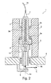
- FIG. 2 a second embodiment of the present invention is shown.
- the same reference numerals are used for corresponding components and elements as in the preceding first embodiment.
- the second embodiment of the present invention differs from the first embodiment essentially in that on the shaft 4 by means of a tensioning means (pull rod) 9, a chuck 10 is attached.
- a laser beam is directed along the longitudinal axis of the shaft.
- the tensioning means 9 is received within the shaft 4.
- the clamping means 9 has in the longitudinal direction on a cavity 9a, through which the injected by the collimator 7 radiation is passed through the shaft 4, is passed at the end of the clamping means 9 in the chuck 10, from where it continues into the glueing unit 6 becomes.
- the sizing unit 6 is rotatably mounted on the chuck 10 by means of a bearing 6b.
- the laser beam L can be guided over the shaft 4 and the chuck 10 in the gluing unit 6, while the gluing unit 6 can rotate around the chuck 10 during machining.
- the bearing 6b may be omitted, whereby the shaft 4, the chuck 10 and the sizing unit 6 are non-rotatably connected with each other.
- the shaft 4 is rotated as in Embodiment 1.
- the storage 6b can also be omitted, whereby chuck 10 and the glueing unit 6 are rotatably connected to each other. In this case, a rotational movement between the chuck 10 and the shaft 4 could be brought about. Thus, the unit of the chuck 10 and the gluing unit 6 would be jointly rotatable.
- FIG. 3 A third embodiment of the present invention is shown, which is a modification of the second embodiment.
- the laser beam L is not guided along the longitudinal axis of the shaft 4, but coupled in a direction substantially perpendicular to the longitudinal axis direction in the chuck 10, and then forwarded to the gluing unit 6.
- the collimator 7 in this third embodiment is not coaxial with the longitudinal axis of the shaft 4, but in one attached to another area of the shaft bearing or in another area of the machine tool.
- the laser beam L is coupled by the collimator 7 in a cavity 2b of the shaft bearing portion 2 and guided along the cavity 2b.
- this cavity 2b extends parallel to the longitudinal axis 4a of the shaft 4.
- an optic 11 eg, a mirror and / or a prism or the like
- a further optics 12 is provided, which deflects the laser beam L in a coaxial with the longitudinal axis 4a of the shaft 4 or identical direction.
- the present invention is spoken by a line of a laser beam.
- the present invention also includes other types of energy and their transmission.
- laser radiation is here, for example, infrared or microwave radiation to call. It is also conceivable to conduct another radiation, for example also heat energy, in the present device.
- the present processing apparatus relates both to a processing apparatus in the continuous technology, as also on CNC machines.
- the latter can be equipped in cantilever or gantry design, in particular with a Fahrportal. It is also possible to use machines with parallel kinematics or robots etc.
- a very wide variety of units can be used, although an edge banding unit has been described above by way of example.
- the unit can also be designed in the form of an insertable into the tool holder focusing device, in particular optics.
- direct machining operations on the workpiece can be carried out by means of the radiation supplied by the radiation device.
- a radiation device (or also generally a power generation device) can be provided for a single processing device or also for a multiplicity of processing devices.
- a distributor would then be provided, for example, which is actuated, for example, via a central control device in order to guide the laser radiation generated by the radiation device to the corresponding processing device.
- FIG. 4 shows the configuration of a mounting unit 6 for attaching a coating material to a workpiece W.
- the coating material is through a supply channel 26 through the unit. 6 passed through and exits at an outlet opening 26a, to be subsequently pressed by means of a pinch roller 24 to the workpiece W.
- the coating unit 6 has in the present embodiment, a deflection mirror 8, by means of which supplied radiation (for example, laser radiation) in the direction of a beam trap 22 can be deflected to the coating material.
- supplied radiation for example, laser radiation
- the radiation impinges on the coating material at an angle deviating from 90 °, wherein reflections may occur depending on the coating material and the type of radiation.
- the coating unit 6 in the present embodiment has a Radiation reflection device, which is formed in the present embodiment as a profiled surface 20. This surface is arranged and arranged such that radiation reflected by the coating material is reflected again onto the coating material.
- the profiling is designed in such a way that the radiation impinging on the profiling can not emerge from the outlet opening 66a, or only to a small extent, so that the radiation is kept away from the outlet opening 26a.
Landscapes
- Engineering & Computer Science (AREA)
- Physics & Mathematics (AREA)
- Optics & Photonics (AREA)
- Mechanical Engineering (AREA)
- Plasma & Fusion (AREA)
- Life Sciences & Earth Sciences (AREA)
- Wood Science & Technology (AREA)
- Forests & Forestry (AREA)
- Laser Beam Processing (AREA)
- Chemical And Physical Treatments For Wood And The Like (AREA)
- Application Of Or Painting With Fluid Materials (AREA)
Abstract
Description
Bearbeitungsvorrichtung nach dem Oberbegriff von Anspruch 1. Gattungsgemäße Bearbeitungsvorrichtungen kommen beispielsweise bei der Bearbeitung von Werkstücken zum Einsatz, die zumindest abschnittsweise aus Holz, Holzwerkstoffen, Kunststoffen, Metallen (wie Beschlägen) oder einer Kombination hiervon, aufgebaut sind z.B. in der Möbel-und Bauelementeindustrie.Processing device according to the preamble of claim 1. Generic processing devices are used for example in the machining of workpieces, which are at least partially constructed of wood, wood materials, plastics, metals (such as fittings) or a combination thereof, e.g. in the furniture and component industry.
Strahlung, insbesondere Laserstrahlung, findet in verschiedenen Fertigungsprozessen zunehmende Anwendung, z.B. beim Trennen, Fügen oder Beschriften. Hierbei wird die durch die Strahlung erzeugte wärme gezielt eingesetzt, um entsprechende Arbeitsschritte durchzuführen.Radiation, in particular laser radiation, is increasingly used in various manufacturing processes, e.g. when separating, joining or labeling. Here, the heat generated by the radiation is used selectively to perform appropriate steps.
Allerdings ist es stets problematisch, eine Strahlführung in eine bekannte Bearbeitungsmaschine zu integrieren, und somit das Einsatzspektrum einer solchen Bearbeitungsmaschine um eine weitere Bearbeitungsart zu erweitern. Oft führen Überlegungen hinsichtlich der Integration einer Strahlführung in eine bekannte Bearbeitungsmaschine zu Nachteilen wie zusätzlichem Konstruktionsaufwand für die Anpassung einer Bearbeitungsvorrichtung an verschiedene Fertigungsaufgaben. Dies führt im Ergebnis zu erhöhten Kosten.However, it is always problematic to integrate a beam guide in a known processing machine, and thus to expand the range of use of such a processing machine to another type of processing. Often considerations regarding the integration of a beam guide in a known processing machine to disadvantages such as additional design effort for the adaptation of a processing device to different manufacturing tasks. As a result, this leads to increased costs.
Der vorliegenden Erfindung liegt die Aufgabe zugrunde, eine Bearbeitungsvorrichtung mit einer Strahlführungseinrichtung bereitzustellen, bei der die Strahlführungseinrichtung bestmöglich in die Maschine integriert wird, ohne die Funktionalität der Maschine zu beeinflussen.The present invention has for its object to provide a processing device with a beam guiding device, in which the beam guiding device is integrated as possible in the machine without affecting the functionality of the machine.
Diese Aufgabe wird durch eine Vorrichtung gemäß Anspruch 1 gelöst. Vorteilhafte Ausführungsformen sind den Unteransprüchen zu entnehmen.This object is achieved by a device according to claim 1. Advantageous embodiments can be found in the dependent claims.
Der Erfindung liegt der Gedanke zugrunde, eine Strahlführungseinrichtung innerhalb einer
Bearbeitungsmaschine derart vorzusehen, dass hierdurch keine wesentlichen Umbauten oder Neukonstruktionen erforderlich sind. Demnach soll an eine Bearbeitungsmaschine, mit der eine gängige Bearbeitung, wie z.B. eine spanende Bearbeitung, durchgeführt werden kann, über eine Schnittstelle eine Energieeinbringung vorgesehen werden, wobei die Weiterleitung der Energie, insbesondere der Strahlungsenergie, innerhalb der Vorrichtung abschnittsweise durch einen Hohlraum einer Welle und/oder einen Hohlraum innerhalb eines an die Welle angeschlossenen Aggregats verläuft.The invention is based on the idea of a beam guiding device within a
To provide processing machine such that thereby no significant modifications or redesigns are required. Accordingly, to a processing machine, with a common processing, such as a machining, can be performed via an interface energy input provided, the forwarding of energy, in particular the radiant energy within the device sections through a cavity of a shaft and / or a cavity extends within an aggregate connected to the shaft.
Es ist in diesem Zusammenhang darauf hinzuweisen, dass der Begriff "Strahlung" im Sinne dieser Anmeldung weit auszulegen ist. Lediglich beispielhaft wird in dieser Anmeldung eine Laserstrahlung erwähnt. Allerdings sind auch Mikrowellenstrahlung, W-Strahlung, Infrarot-Strahlung, Wärmestrahlung, usw. mit umfasst. Demnach ist "Strahlung" im Sinne dieser Anmeldung als Energieübertragung von einer Erzeugerquelle zu einer Bearbeitungszone zu verstehen.It should be noted in this context that the term "radiation" in the context of this application is to be interpreted broadly. For example only, a laser radiation is mentioned in this application. However, microwave radiation, W radiation, infrared radiation, heat radiation, etc. are also included. Accordingly, "radiation" in the context of this application is to be understood as energy transmission from a generator source to a processing zone.
Erfindungsgemäß wird demnach eine Vorrichtung bereitgestellt, mit: einer Strahlungseinrichtung zum Erzeugen und/oder Übertragen einer Strahlung, vorzugsweise eines Laserstrahls, und einer Spindeleinheit mit einer in einem Wellenlagerabschnitt drehbaren Welle und einer Aufnahme für Bearbeitungswerkzeuge und/oder Bearbeitungsaggregate.According to the invention, therefore, a device is provided, comprising: a radiation device for generating and / or transmitting radiation, preferably a laser beam, and a spindle unit with a rotatable in a shaft bearing portion shaft and a receptacle for processing tools and / or processing units.
Die neuartige Vorrichtung kennzeichnet sich dadurch, dass die Welle und/ oder der Wellenlagerabschnitt zumindest abschnittsweise einen Hohlraum aufweisen, und die Strahlungseinrichtung derart angeordnet ist, dass die Strahlung zumindest abschnittsweise innerhalb des Hohlraumes verläuft.The novel device is characterized in that the shaft and / or the shaft bearing section at least partially have a cavity, and the radiation device is arranged such that the radiation extends at least partially within the cavity.
In einer bevorzugten Ausführungsform mündet der Hohlraum, der abschnittsweise in der Welle und/oder dem
Wellenlagerabschnitt verläuft, im Bereich der Aufnahme für Bearbeitungswerkzeuge und/oder Bearbeitungsaggregate, oder in einem an die Welle angeschlossenen Aggregat. Letzteres kann beispielsweise als Spannfutter ausgebildet sein. Wird somit die Strahlung durch den Hohlraum geführt, so kommt die Strahlung letztlich am genannten Mündungsbereich an, und kann von dort aus in ein bestimmtes Bearbeitungsaggregat weitergeleitet werde, so z.B. ein Verleimaggregat.In a preferred embodiment, the cavity that opens in sections in the shaft and / or the
Shaft bearing section runs, in the area of recording for machining tools and / or processing units, or in an aggregate connected to the shaft. The latter can be formed for example as a chuck. Thus, if the radiation is guided through the cavity, then the radiation ultimately arrives at said opening area, and from there it can be passed on to a specific processing unit, for example a gluing unit.
Darüber hinaus ist es in einer Ausführungsform vorgesehen, dass sich der Hohlraum in Achsrichtung der Welle durch die gesamte Welle hindurch erstreckt. Somit kann die Welle selbst als Leitungsabschnitt für die Strahlung verwendet werden. Weiter kann es vorgesehen sein, dass sich der Hohlraum durch ein durch die Welle verlaufendes Spannmittel erstreckt. Bei einem solchen Spannmittel kann es sich beispielsweise um eine Zugstange handeln, mit der beispielsweise ein Spannfutter an der Welle lösbar angebracht werden kann. Auf diese Weise wird die Übertragung der Strahlung innerhalb der erfindungsgemäßen Vorrichtung besonders günstig integriert.Moreover, in one embodiment it is provided that the cavity extends in the axial direction of the shaft through the entire shaft. Thus, the wave itself can be used as a conduit section for the radiation. Furthermore, provision may be made for the cavity to extend through a tensioning means extending through the shaft. In such a tensioning means may be, for example, a pull rod with which, for example, a chuck can be releasably attached to the shaft. In this way, the transmission of radiation within the device according to the invention is integrated particularly favorably.
Weiter kann es vorgesehen sein, dass die Spindeleinheit in mindestens einer, bevorzugt in drei, unterschiedlichen Richtungen verfahrbar ist. Alternativ oder zusätzlich kann die Spindeleinheit um mindestens eine Achse verschwenkbar sein. Besonders bevorzugt ist die Ausgestaltung der Spindeleinheit als 5-Achs-Einheit (mindestens drei translatorische und 2 rotatorische Achsen).Furthermore, it can be provided that the spindle unit can be moved in at least one, preferably in three, different directions. Alternatively or additionally the spindle unit can be pivoted about at least one axis. Particularly preferred is the configuration of the spindle unit as a 5-axis unit (at least three translational and 2 rotary axes).
Auch kann die Strahlungseinrichtung direkt oder indirekt mit der Spindeleinheit verbunden, oder gar mit dieser verfahrbar sein. Wird die Strahlungseinrichtung indirekt an die Spindeleinheit angeschlossen, so kann es vorgesehen sein, dass die Strahlungseinrichtung mehrere Vorrichtungen mit Strahlung bedient.Also, the radiation device can be directly or indirectly connected to the spindle unit, or even be moved with this. If the radiation device is connected indirectly to the spindle unit, then it can be provided that the radiation device operates a plurality of devices with radiation.
Weiter sind verschiedene Varianten denkbar, mit denen ein an der Welle angeschlossenes Bearbeitungsaggregat, bevorzugt Verleimaggregat, drehbar ist. Zum Einen kann eine Drehung des Bearbeitungsaggregats, und somit des austretenden Laserstrahls, durch eine Drehung der Welle und des daran befestigten Bearbeitungsaggregats erreicht werden. In einer anderen Variante ist das Bearbeitungsaggregat relativ zur Welle drehbar gelagert. In einer weiteren Variante kann anstelle der Welle auch ein zwischen Welle und
Bearbeitungsaggregat angebrachtes Spannfutter gedreht werden.Furthermore, various variants are conceivable with which a processing unit connected to the shaft, preferably a glueing unit, can be rotated. On the one hand, a rotation of the processing unit, and thus of the exiting laser beam, can be achieved by a rotation of the shaft and of the processing unit attached thereto. In another variant, the processing unit is rotatably mounted relative to the shaft. In a further variant, instead of the wave also between a wave and
Machining unit attached chuck are rotated.
In einer besonderen Ausführungsform ist das Bearbeitungsaggregat als sogenanntes Anbringaggregat
ausgeführt. Mit diesem kann ein Beschichtungsmaterial auf ein Werkstück aufgebracht werden. Die über die erfindungsgemäße Vorrichtung zugeführte Strahlung wird in diesem Fall dazu verwendet, das Werkstück und/oder das Beschichtungsmaterial (ggf. unter Nutzung einer Wechselwirkung von Werkstück und Beschichtungsmaterial) zu aktivieren, bevorzugt zu erwärmen, um anschließend das Beschichtungsmaterial auf das Werkstück aufbringen zu können.In a particular embodiment, the processing unit is a so-called attachment unit
executed. With this, a coating material can be applied to a workpiece. The radiation supplied via the device according to the invention is in this case used to activate, preferably to heat, the workpiece and / or the coating material (if appropriate using an interaction between the workpiece and the coating material) in order subsequently to be able to apply the coating material to the workpiece ,
In einer weiteren Ausführungsform ist das
Bearbeitungsaggregat entweder in die Aufnahme der Welle oder in das an die Welle angeschlossene Aggregat (Spannfutter) einwechselbar und aus dieser/diesem entnehmbar. Hierdurch weist die erfindungsgemäße Vorrichtung eine besonders hohe Flexibilität auf, denn es können verschiedenartige Bearbeitungsaggregate eingewechselt werden, wobei teilweise die in die Vorrichtung zugeführte Strahlung für die Bearbeitung verwendet wird.In a further embodiment this is
Machining unit either in the receptacle of the shaft or in the unit connected to the shaft (chuck) exchangeable and removable from this / this. As a result, the device according to the invention has a particularly high level of flexibility, since various types of processing units can be loaded, in which case the radiation supplied into the device is used in part for the processing.
- Figur 1FIG. 1
- zeigt eine Schnittansicht einer ersten bevorzugten Ausführungsform der vorliegenden Erfindung.shows a sectional view of a first preferred embodiment of the present invention.
- Figur 2FIG. 2
- zeigt eine Schnittansicht einer zweiten bevorzugten Ausführungsform der vorliegenden Erfindung.shows a sectional view of a second preferred embodiment of the present invention.
- Figur 3FIG. 3
- zeigt eine Schnittansicht einer dritten bevorzugten Ausführungsform der vorliegenden Erfindung.shows a sectional view of a third preferred embodiment of the present invention.
- Figur 4FIG. 4
- zeigt eine Draufsicht einer möglichen Variante der vorliegenden Erfindung.shows a plan view of a possible variant of the present invention.
Nachfolgend werden unter Bezugnahme auf die beigefügten Zeichnungen bevorzugte Ausführungsformen der vorliegenden Erfindung im Detail erläutert.Hereinafter, preferred embodiments of the present invention will be explained in detail with reference to the accompanying drawings.
In einem Endabschnitt der Welle 4, der freigelegt ist, wenn kein Aggregat an der Welle angebracht ist, befindet sich ein Anschlussabschnitt 5, an dem verschiedene Bearbeitungsaggregate angebracht werden können. Im vorliegenden Beispiel ist am Anschlussabschnitt 5 der Welle 4 direkt ein Verleimaggregat 6 angebracht.In an end portion of the
Innerhalb der Welle 4 ist ein sich entlang der Längsachse 4a der Welle 4 erstreckender Hohlraum 4b vorgesehen. Ein entsprechender, sich ebenfalls in Längsrichtung der Welle 4 erstreckender Hohlraum ist am Verleimaggregat 6 derart ausgebildet, dass sich die Hohlräume 4b und 6a in einem Bereich um die Längsachse der Welle aneinander anschließen.Within the
An dem vom Anschlussabschnitt 5 entgegengesetzten Ende der Welle 4 ist am Wellenlagerabschnitt 2 ein Kollimator 7 angebracht, der über einen Lichtwellenleiter 7a mit einer nicht dargestellten Strahlgenerierungseinrichtung, hier einem Laser, verbunden ist. Alternativ hierzu kann die Strahlgenerierungseinrichtung auch direkt am Wellenlagerabschnitt 2, oder an der Bearbeitungsvorrichtung 1 angebracht sein.At the end of the
Im vorliegenden Beispiel bewirkt der Kollimator 7, dass ein über den Lichtwellenleiter 7a zugeführte Laserstrahl L in den Hohlraum 4b der Welle 4 eingekoppelt wird, der dann entlang der Längsachse 4a der Welle 4 im Hohlraum 4b fortschreitet und über den am Verleimaggregat 6 vorgesehenen Hohlraum 6a in das Verleimaggregat 6 eintritt. Innerhalb des Verleimaggregats ist eine Optik 7, insbesondere ein Spiegel und/oder ein Prisma, vorgesehen, um den in das Verleimaggregat 6 eingekoppelten Laserstrahl L umzulenken. Die verschiedenen Bearbeitungsarten, die mit dem somit eingekoppelten Laserstrahl durchgeführt werden können, werden später erläutert. An dieser Stelle sei bereits erwähnt, dass innerhalb des Verleimaggregats weitere Spiegel vorgesehen sein können, damit der Laserstrahl L zur Bearbeitungszone umgelenkt wird.In the present example, the
Ausführungsform 1 gemäß
In
Die zweite Ausführungsform der vorliegenden Erfindung unterscheidet sich von der ersten Ausführungsform im Wesentlichen dadurch, dass an der Welle 4 mittels eines Spannmittels (Zugstange) 9 ein Spannfutter 10 befestigt ist. Wie in der ersten Ausführungsform wird ein Laserstrahl entlang der Längsachse der Welle geleitet. Allerdings ist innerhalb der Welle 4 das Spannmittel 9 aufgenommen. Das Spannmittel 9 weist jedoch in der Längsrichtung einen Hohlraum 9a auf, durch den die durch den Kollimator 7 eingekoppelte Strahlung durch die Welle 4 geleitet wird, am Ende des Spannmittels 9 in das Spannfutter 10 geleitet wird, von wo aus es in das Verleimaggregat 6 weitergeführt wird. Hierbei ist es gemäß Ausführungsform 2 der vorliegenden Erfindung vorgesehen, dass das Verleimaggregat 6 mittels einer Lagerung 6b drehbar am Spannfutter 10 angebracht ist. Somit kann der Laserstrahl L über die Welle 4 und das Spannfutter 10 in das Verleimaggregat 6 geführt werden, während sich das Verleimaggregat 6 während der Bearbeitung um das Spannfutter 10 drehen kann.The second embodiment of the present invention differs from the first embodiment essentially in that on the
Alternativ hierzu kann auch, wie in Ausführungsform 1, die Lagerung 6b weggelassen werden, wodurch die Welle 4, das Spannfutter 10 und das Verleimaggregat 6 drehfest miteinander verbunden sind. Wird eine Drehung des Laserstrahls L in eine andere Austrittsrichtung gewünscht, wird die Welle 4 wie in Ausführungsform 1 gedreht.Alternatively, as in Embodiment 1, the
In einer zu dieser Alternative weiteren Variante kann ebenfalls die Lagerung 6b weggelassen werden, wodurch Spannfutter 10 und das Verleimaggregat 6 drehfest miteinander verbunden sind. In diesem Fall könnte eine Drehbewegung zwischen dem Spannfutter 10 und der Welle 4 herbeigeführt werden. Somit wäre die Einheit aus dem Spannfutter 10 und dem Verleimaggregat 6 gemeinschaftlich drehbar.In a variant of this alternative further, the
Ebenso ist es möglich, die Welle 4 verdrehfest anzuordnen, und nur das Spannfutter 10 verdrehbar vorzusehen, das dann als "Welle" fungiert.It is also possible to arrange the
In
Hierzu ist der Kollimator 7 in dieser dritten Ausführungsform nicht koaxial zur Längsachse der Welle 4, sondern in einem anderen Bereich der Wellenlagerung oder auch in einem anderen Bereich der Bearbeitungsmaschine angebracht. Der Laserstrahl L wird vom Kollimator 7 in einen Hohlraum 2b des Wellenlagerabschnitts 2 eingekoppelt und entlang des Hohlraums 2b geführt. Im vorliegenden Ausführungsbeispiel verläuft dieser Hohlraum 2b parallel zur Längsachse 4a der Welle 4. Bei Anbringung einer entsprechenden Optik kann jedoch auch eine andere Strahlführung innerhalb des Wellenlagerabschnitts 2 realisiert werden.For this purpose, the
Um den Laserstrahl L nach Eintritt in den Hohlraum 2b des Wellenlagerabschnitts 2 umzulenken, ist eine Optik 11 (z. B. ein Spiegel und/oder ein Prisma oder dergleichen) innerhalb des Hohlraums 2b vorgesehen. Diese bewirkt, dass der Laserstrahl L, wie bereits beschrieben, in einer zur Längsachse 4a der Welle 4 senkrechten Richtung in das Spannfutter 10 geleitet wird. Im Spannfutter 10 ist eine weitere Optik 12 vorgesehen, die den Laserstrahl L in eine zur Längsachse 4a der Welle 4 koaxialen oder identischen Richtung umlenkt.In order to redirect the laser beam L after entering the
Die Ausführungsform gemäß
In den vorliegenden Ausführungsformen wird von einer Leitung eines Laserstrahls gesprochen. Allerdings umfasst die vorliegende Erfindung auch andere Energiearten und deren Weiterleitung. Neben Laserstrahlung ist hier beispielsweise infrarotes Licht oder Mikrowellenstrahlung zu nennen. Auch ist es denkbar, eine andere Strahlung, beispielsweise auch Wärmenergie, in der vorliegenden Vorrichtung zu leiten.In the present embodiments is spoken by a line of a laser beam. However, the present invention also includes other types of energy and their transmission. In addition to laser radiation is here, for example, infrared or microwave radiation to call. It is also conceivable to conduct another radiation, for example also heat energy, in the present device.
Die vorliegende Bearbeitungsvorrichtung bezieht sich sowohl auf eine Bearbeitungsvorrichtung in der Durchlauftechnik, als auch auf CNC-Bearbeitungsmaschinen. Letztere kann in Ausleger- oder Portalbauweise, insbesondere mit einem Fahrportal, ausgerüstet sein. Auch ist der Einsatz bei Maschinen mit Parallelkinematik oder bei Robotern etc. möglich. Dabei können unterschiedlichste Aggregate zum Einsatz kommen, obgleich vorstehend beispielhaft ein Kantenanleimaggregat beschrieben wurde.The present processing apparatus relates both to a processing apparatus in the continuous technology, as also on CNC machines. The latter can be equipped in cantilever or gantry design, in particular with a Fahrportal. It is also possible to use machines with parallel kinematics or robots etc. A very wide variety of units can be used, although an edge banding unit has been described above by way of example.
So kann das Aggregat auch in Form einer in die Werkzeugaufnahme einsetzbaren Fokussiereinrichtung, insbesondere Optik ausgebildet sein. Hierdurch können beispielsweise direkt Bearbeitungen am Werkstück mittels der von der Strahlungseinrichtung zugeführten Strahlung durchgeführt werden.Thus, the unit can also be designed in the form of an insertable into the tool holder focusing device, in particular optics. As a result, for example, direct machining operations on the workpiece can be carried out by means of the radiation supplied by the radiation device.
Wie bereits erläutert, kann eine Strahlungseinrichtung (oder auch allgemein eine Energieerzeugungseinrichtung) für eine einzelne Bearbeitungsvorrichtung, oder auch für eine Vielzahl von Bearbeitungsvorrichtungen vorgesehen sein. Im letzteren Fall wäre dann beispielsweise ein Verteiler vorzusehen, der beispielsweise über eine zentrale Steuereinrichtung betätigt wird, um die von der Strahlungseinrichtung erzeugte Laserstrahlung zur entsprechenden Bearbeitungsvorrichtung zu leiten.As already explained, a radiation device (or also generally a power generation device) can be provided for a single processing device or also for a multiplicity of processing devices. In the latter case, a distributor would then be provided, for example, which is actuated, for example, via a central control device in order to guide the laser radiation generated by the radiation device to the corresponding processing device.
Ferner können zusätzlich zu der Strahlungseinrichtung auch weitere und ggf. andersartige Energiequellen vorgesehen sein, beispielsweise um einen oder mehrere der jeweiligen Fügepartner vorzuwärmen.Furthermore, in addition to the radiation device, further and optionally different types of energy sources may also be provided, for example to preheat one or more of the respective joining partners.
Eine weitere Modifikation der vorliegenden Erfindung, die mit allen oben beschriebenen Ausführungsformen vorteilhaft kombiniert werden kann, ist in
Das Beschichtungsaggregat 6 besitzt in der vorliegenden Ausführungsform einen Umlenkspiegel 8, mittels dessen zugeführte Strahlung (beispielsweise Laserstrahlung) in Richtung einer Strahlfalle 22 auf das Beschichtungsmaterial umgelenkt werden kann. Dabei trifft die Strahlung in der vorliegenden Ausführungsform unter einem von 90° abweichenden Winkel auf das Beschichtungsmaterial, wobei je nach Beschichtungsmaterial und Strahlungsart Reflektionen auftreten können.The
Vor diesem Hintergrund besitzt das Beschichtungsaggregat 6 in der vorliegenden Ausführungsform eine
Strahlungsreflexionseinrichtung, die in der vorliegenden Ausführungsform als profilierte Fläche 20 ausgebildet ist. Diese Fläche ist derart angeordnet und eingerichtet, dass von dem Beschichtungsmaterial reflektierte Strahlung erneut auf das Beschichtungsmaterial reflektiert wird. Dabei ist die Profilierung derart ausgestaltet, dass die auf die Profilierung auftreffende Strahlung nicht oder nur in geringem Ausmaß aus der Austrittsöffnung 66a austreten kann, sodass die Strahlung von der Austrittsöffnung 26a ferngehalten wird.Against this background, the
Radiation reflection device, which is formed in the present embodiment as a profiled
Neben der in
Claims (15)
Applications Claiming Priority (1)
| Application Number | Priority Date | Filing Date | Title |
|---|---|---|---|
| DE102011002696A DE102011002696A1 (en) | 2011-01-14 | 2011-01-14 | processing device |
Publications (2)
| Publication Number | Publication Date |
|---|---|
| EP2476504A1 true EP2476504A1 (en) | 2012-07-18 |
| EP2476504B1 EP2476504B1 (en) | 2015-06-03 |
Family
ID=45495688
Family Applications (1)
| Application Number | Title | Priority Date | Filing Date |
|---|---|---|---|
| EP11196018.3A Active EP2476504B1 (en) | 2011-01-14 | 2011-12-29 | Processing device |
Country Status (6)
| Country | Link |
|---|---|
| US (1) | US8752302B2 (en) |
| EP (1) | EP2476504B1 (en) |
| CN (1) | CN102581481B (en) |
| BR (1) | BR102012000930B1 (en) |
| DE (1) | DE102011002696A1 (en) |
| ES (1) | ES2544282T3 (en) |
Cited By (1)
| Publication number | Priority date | Publication date | Assignee | Title |
|---|---|---|---|---|
| DE102014216108A1 (en) * | 2014-08-13 | 2016-02-18 | Volkswagen Aktiengesellschaft | Method for producing an interior trim element and a tool for carrying out the method |
Families Citing this family (6)
| Publication number | Priority date | Publication date | Assignee | Title |
|---|---|---|---|---|
| DE102013218483A1 (en) * | 2013-09-16 | 2015-03-19 | Homag Holzbearbeitungssysteme Gmbh | Method for laser processing and processing machine |
| DE102013225490A1 (en) * | 2013-12-10 | 2015-06-11 | Siemens Aktiengesellschaft | Oscillating welding process |
| DE102013226214A1 (en) * | 2013-12-17 | 2015-06-18 | Homag Holzbearbeitungssysteme Gmbh | processing device |
| DE102017200080A1 (en) * | 2017-01-05 | 2018-07-05 | Volkswagen Aktiengesellschaft | Hollow shaft and non-rotating lens laser tool |
| DE102018125609B4 (en) * | 2018-10-16 | 2021-11-25 | Surteco Gmbh | Method and device for fastening an edging strip |
| US11931823B2 (en) * | 2019-02-05 | 2024-03-19 | Dukane Ias, Llc | Systems and methods for laser-welding a workpiece with a laser beam that reaches inaccessible areas of the workpiece using multiple reflecting parts |
Citations (8)
| Publication number | Priority date | Publication date | Assignee | Title |
|---|---|---|---|---|
| EP0158866A2 (en) * | 1984-03-24 | 1985-10-23 | Trumpf GmbH & Co | Machine tool for processing a work piece mechanically and thermally |
| EP0491242A1 (en) * | 1990-12-18 | 1992-06-24 | MAHO Aktiengesellschaft | Machine-tool for abrasive machining workpieces with a laser beam |
| DE4113633A1 (en) * | 1991-04-26 | 1992-10-29 | Manfred Toeller | Dual spindle machining head - comprising one spindle with laser cutting head, second spindle with other tooling and common vertical axis drive |
| US5376061A (en) * | 1992-04-20 | 1994-12-27 | Fanuc Ltd. | Compound machine tool capable of laser beam processing |
| EP0958884A1 (en) * | 1998-05-19 | 1999-11-24 | Lastec Laserjob AG | Process for machining workpieces and machine tool |
| US20050133486A1 (en) * | 2003-12-19 | 2005-06-23 | Baker Martin C. | Hand-held laser welding wand having removable filler media delivery extension tips |
| EP1810767A1 (en) * | 2006-01-24 | 2007-07-25 | Jenoptik Automatisierungstechnik GmbH | Combined apparatus for metal working with a milling cutter and a laser |
| DE102009008284A1 (en) * | 2009-02-10 | 2010-08-12 | Fraunhofer-Gesellschaft zur Förderung der angewandten Forschung e.V. | Laser-supported machining of high-strength workpiece, uses rotating tool on drive shaft and laser beam bundle passing through hole in shaft while overlapping rotational axis of shaft |
Family Cites Families (11)
| Publication number | Priority date | Publication date | Assignee | Title |
|---|---|---|---|---|
| US2486503A (en) * | 1946-07-10 | 1949-11-01 | Allen C Stephens | Target indicator |
| US3267794A (en) * | 1961-01-16 | 1966-08-23 | Atkinson Guy F Co | Optical alignment system for detecting and correcting distortion in a structure |
| US4438567A (en) * | 1981-12-07 | 1984-03-27 | Raiha A P | Center locator for alignment of work to machine spindle |
| US4791715A (en) * | 1987-04-03 | 1988-12-20 | Cimco, Inc. | Method and apparatus for assembly of cassette pulley |
| US20030185273A1 (en) * | 1993-09-17 | 2003-10-02 | Hollander Milton Bernard | Laser directed temperature measurement |
| JP3965593B2 (en) * | 1998-07-08 | 2007-08-29 | 株式会社トプコン | Surveying device centripetal position measuring device and surveying instrument |
| US6857193B2 (en) * | 2000-10-04 | 2005-02-22 | Darryl H. Kallesen | Location projector apparatus and methods |
| US6892464B2 (en) * | 2002-03-13 | 2005-05-17 | Kabushiki Kaisha Topcon | Laser sighting device |
| US6823599B1 (en) * | 2003-10-08 | 2004-11-30 | Northrop Grumman Corporation | Alignment structure and method for multiple field camera |
| US7487596B2 (en) * | 2004-06-25 | 2009-02-10 | Irwin Industrial Tool Company | Laser line projected on an edge of a surface |
| US7992312B2 (en) * | 2008-07-10 | 2011-08-09 | Krasko Michael E | Positioning system for laser alignment tools |
-
2011
- 2011-01-14 DE DE102011002696A patent/DE102011002696A1/en not_active Ceased
- 2011-12-29 ES ES11196018.3T patent/ES2544282T3/en active Active
- 2011-12-29 EP EP11196018.3A patent/EP2476504B1/en active Active
-
2012
- 2012-01-11 US US13/347,906 patent/US8752302B2/en not_active Expired - Fee Related
- 2012-01-12 CN CN201210008764.6A patent/CN102581481B/en active Active
- 2012-01-13 BR BR102012000930-7A patent/BR102012000930B1/en not_active IP Right Cessation
Patent Citations (8)
| Publication number | Priority date | Publication date | Assignee | Title |
|---|---|---|---|---|
| EP0158866A2 (en) * | 1984-03-24 | 1985-10-23 | Trumpf GmbH & Co | Machine tool for processing a work piece mechanically and thermally |
| EP0491242A1 (en) * | 1990-12-18 | 1992-06-24 | MAHO Aktiengesellschaft | Machine-tool for abrasive machining workpieces with a laser beam |
| DE4113633A1 (en) * | 1991-04-26 | 1992-10-29 | Manfred Toeller | Dual spindle machining head - comprising one spindle with laser cutting head, second spindle with other tooling and common vertical axis drive |
| US5376061A (en) * | 1992-04-20 | 1994-12-27 | Fanuc Ltd. | Compound machine tool capable of laser beam processing |
| EP0958884A1 (en) * | 1998-05-19 | 1999-11-24 | Lastec Laserjob AG | Process for machining workpieces and machine tool |
| US20050133486A1 (en) * | 2003-12-19 | 2005-06-23 | Baker Martin C. | Hand-held laser welding wand having removable filler media delivery extension tips |
| EP1810767A1 (en) * | 2006-01-24 | 2007-07-25 | Jenoptik Automatisierungstechnik GmbH | Combined apparatus for metal working with a milling cutter and a laser |
| DE102009008284A1 (en) * | 2009-02-10 | 2010-08-12 | Fraunhofer-Gesellschaft zur Förderung der angewandten Forschung e.V. | Laser-supported machining of high-strength workpiece, uses rotating tool on drive shaft and laser beam bundle passing through hole in shaft while overlapping rotational axis of shaft |
Cited By (1)
| Publication number | Priority date | Publication date | Assignee | Title |
|---|---|---|---|---|
| DE102014216108A1 (en) * | 2014-08-13 | 2016-02-18 | Volkswagen Aktiengesellschaft | Method for producing an interior trim element and a tool for carrying out the method |
Also Published As
| Publication number | Publication date |
|---|---|
| CN102581481A (en) | 2012-07-18 |
| EP2476504B1 (en) | 2015-06-03 |
| US20120180328A1 (en) | 2012-07-19 |
| US8752302B2 (en) | 2014-06-17 |
| BR102012000930B1 (en) | 2019-11-19 |
| BR102012000930A8 (en) | 2018-03-06 |
| ES2544282T3 (en) | 2015-08-28 |
| BR102012000930A2 (en) | 2013-09-24 |
| DE102011002696A1 (en) | 2012-07-19 |
| CN102581481B (en) | 2016-02-10 |
Similar Documents
| Publication | Publication Date | Title |
|---|---|---|
| EP2476504B1 (en) | Processing device | |
| EP2422947B1 (en) | Device for coating workpieces | |
| EP2142333B1 (en) | Apparatus for working a surface of a workpiece by means of laser radiation | |
| DE2943228C2 (en) | ||
| DE3807471A1 (en) | DEVICE FOR GUIDING OPTICAL RAYS | |
| EP2412471A2 (en) | Device and method for thermal machining a workpiece using laser beams | |
| WO2012107395A1 (en) | Laser-machining device | |
| WO2004058485A1 (en) | Method and device for welding thermoplastic material shaped parts, particularly for contour-welding three-dimensional shaped parts | |
| EP2952316A1 (en) | Fibre application tool, fibre laying device, fibre laying method and production method | |
| DE202007001346U1 (en) | Apparatus for cutting through articles of brittle material, e.g. glass or ceramic, by directed laser-induced stress cracking, includes concave reflectors with opening(s) for passage of laser radiation | |
| DE19632625A1 (en) | Method and device for welding two components | |
| DE102011116833A1 (en) | Laser machine for processing a workpiece, comprises a laser source for processing a workpiece and for adjusting beam on the workpiece, and a unit for rotating the laser beam around the beam axis | |
| EP3478443A2 (en) | Device for introducing a lens system into the beam path of a laser machining head, and laser machining head comprising same | |
| EP0462324B1 (en) | Clamping device for clamping work-pieces | |
| WO2015173313A1 (en) | Laser machining head comprising a lens-changing system | |
| EP2316606A2 (en) | Device for transmission welding of components through a ring-shaped contact zone | |
| EP3144102B1 (en) | Device for post-processing of at least one flat workpiece | |
| DE202017101590U1 (en) | Device for guiding a laser beam onto a workpiece | |
| EP1445082B1 (en) | Edge-banding machine | |
| DE102010026107A1 (en) | Apparatus and method for process gas accompanied machining of workpieces with energetic radiation | |
| EP2468445B1 (en) | Laser processing machine with a diode laser, which laser beam can rotate around its axis, and method of machining a workpiece | |
| EP1839828A2 (en) | Machining device, in particular circular saw | |
| DE102018125609B4 (en) | Method and device for fastening an edging strip | |
| EP2445688B1 (en) | Machining center | |
| EP3046718B1 (en) | Method and device for laser working |
Legal Events
| Date | Code | Title | Description |
|---|---|---|---|
| PUAI | Public reference made under article 153(3) epc to a published international application that has entered the european phase |
Free format text: ORIGINAL CODE: 0009012 |
|
| AK | Designated contracting states |
Kind code of ref document: A1 Designated state(s): AL AT BE BG CH CY CZ DE DK EE ES FI FR GB GR HR HU IE IS IT LI LT LU LV MC MK MT NL NO PL PT RO RS SE SI SK SM TR |
|
| AX | Request for extension of the european patent |
Extension state: BA ME |
|
| 17P | Request for examination filed |
Effective date: 20120830 |
|
| GRAP | Despatch of communication of intention to grant a patent |
Free format text: ORIGINAL CODE: EPIDOSNIGR1 |
|
| RIC1 | Information provided on ipc code assigned before grant |
Ipc: B27C 9/00 20060101ALI20150302BHEP Ipc: B29C 37/00 20060101ALI20150302BHEP Ipc: B23K 26/00 20140101ALI20150302BHEP Ipc: B23K 26/34 20140101AFI20150302BHEP Ipc: B23K 26/14 20140101ALI20150302BHEP Ipc: B23P 23/02 20060101ALI20150302BHEP |
|
| INTG | Intention to grant announced |
Effective date: 20150324 |
|
| GRAS | Grant fee paid |
Free format text: ORIGINAL CODE: EPIDOSNIGR3 |
|
| GRAA | (expected) grant |
Free format text: ORIGINAL CODE: 0009210 |
|
| AK | Designated contracting states |
Kind code of ref document: B1 Designated state(s): AL AT BE BG CH CY CZ DE DK EE ES FI FR GB GR HR HU IE IS IT LI LT LU LV MC MK MT NL NO PL PT RO RS SE SI SK SM TR |
|
| REG | Reference to a national code |
Ref country code: GB Ref legal event code: FG4D Free format text: NOT ENGLISH |
|
| REG | Reference to a national code |
Ref country code: CH Ref legal event code: EP |
|
| REG | Reference to a national code |
Ref country code: AT Ref legal event code: REF Ref document number: 729660 Country of ref document: AT Kind code of ref document: T Effective date: 20150715 Ref country code: IE Ref legal event code: FG4D Free format text: LANGUAGE OF EP DOCUMENT: GERMAN |
|
| REG | Reference to a national code |
Ref country code: DE Ref legal event code: R096 Ref document number: 502011006987 Country of ref document: DE |
|
| REG | Reference to a national code |
Ref country code: ES Ref legal event code: FG2A Ref document number: 2544282 Country of ref document: ES Kind code of ref document: T3 Effective date: 20150828 |
|
| PG25 | Lapsed in a contracting state [announced via postgrant information from national office to epo] |
Ref country code: NO Free format text: LAPSE BECAUSE OF FAILURE TO SUBMIT A TRANSLATION OF THE DESCRIPTION OR TO PAY THE FEE WITHIN THE PRESCRIBED TIME-LIMIT Effective date: 20150903 Ref country code: LT Free format text: LAPSE BECAUSE OF FAILURE TO SUBMIT A TRANSLATION OF THE DESCRIPTION OR TO PAY THE FEE WITHIN THE PRESCRIBED TIME-LIMIT Effective date: 20150603 Ref country code: FI Free format text: LAPSE BECAUSE OF FAILURE TO SUBMIT A TRANSLATION OF THE DESCRIPTION OR TO PAY THE FEE WITHIN THE PRESCRIBED TIME-LIMIT Effective date: 20150603 Ref country code: HR Free format text: LAPSE BECAUSE OF FAILURE TO SUBMIT A TRANSLATION OF THE DESCRIPTION OR TO PAY THE FEE WITHIN THE PRESCRIBED TIME-LIMIT Effective date: 20150603 |
|
| REG | Reference to a national code |
Ref country code: NL Ref legal event code: MP Effective date: 20150603 |
|
| REG | Reference to a national code |
Ref country code: LT Ref legal event code: MG4D |
|
| PG25 | Lapsed in a contracting state [announced via postgrant information from national office to epo] |
Ref country code: GR Free format text: LAPSE BECAUSE OF FAILURE TO SUBMIT A TRANSLATION OF THE DESCRIPTION OR TO PAY THE FEE WITHIN THE PRESCRIBED TIME-LIMIT Effective date: 20150904 Ref country code: RS Free format text: LAPSE BECAUSE OF FAILURE TO SUBMIT A TRANSLATION OF THE DESCRIPTION OR TO PAY THE FEE WITHIN THE PRESCRIBED TIME-LIMIT Effective date: 20150603 Ref country code: LV Free format text: LAPSE BECAUSE OF FAILURE TO SUBMIT A TRANSLATION OF THE DESCRIPTION OR TO PAY THE FEE WITHIN THE PRESCRIBED TIME-LIMIT Effective date: 20150603 Ref country code: BG Free format text: LAPSE BECAUSE OF FAILURE TO SUBMIT A TRANSLATION OF THE DESCRIPTION OR TO PAY THE FEE WITHIN THE PRESCRIBED TIME-LIMIT Effective date: 20150903 |
|
| PG25 | Lapsed in a contracting state [announced via postgrant information from national office to epo] |
Ref country code: EE Free format text: LAPSE BECAUSE OF FAILURE TO SUBMIT A TRANSLATION OF THE DESCRIPTION OR TO PAY THE FEE WITHIN THE PRESCRIBED TIME-LIMIT Effective date: 20150603 |
|
| PG25 | Lapsed in a contracting state [announced via postgrant information from national office to epo] |
Ref country code: CZ Free format text: LAPSE BECAUSE OF FAILURE TO SUBMIT A TRANSLATION OF THE DESCRIPTION OR TO PAY THE FEE WITHIN THE PRESCRIBED TIME-LIMIT Effective date: 20150603 Ref country code: PL Free format text: LAPSE BECAUSE OF FAILURE TO SUBMIT A TRANSLATION OF THE DESCRIPTION OR TO PAY THE FEE WITHIN THE PRESCRIBED TIME-LIMIT Effective date: 20150603 Ref country code: PT Free format text: LAPSE BECAUSE OF FAILURE TO SUBMIT A TRANSLATION OF THE DESCRIPTION OR TO PAY THE FEE WITHIN THE PRESCRIBED TIME-LIMIT Effective date: 20151006 Ref country code: IS Free format text: LAPSE BECAUSE OF FAILURE TO SUBMIT A TRANSLATION OF THE DESCRIPTION OR TO PAY THE FEE WITHIN THE PRESCRIBED TIME-LIMIT Effective date: 20151003 Ref country code: SK Free format text: LAPSE BECAUSE OF FAILURE TO SUBMIT A TRANSLATION OF THE DESCRIPTION OR TO PAY THE FEE WITHIN THE PRESCRIBED TIME-LIMIT Effective date: 20150603 Ref country code: RO Free format text: LAPSE BECAUSE OF NON-PAYMENT OF DUE FEES Effective date: 20150603 |
|
| REG | Reference to a national code |
Ref country code: DE Ref legal event code: R097 Ref document number: 502011006987 Country of ref document: DE |
|
| PLBE | No opposition filed within time limit |
Free format text: ORIGINAL CODE: 0009261 |
|
| STAA | Information on the status of an ep patent application or granted ep patent |
Free format text: STATUS: NO OPPOSITION FILED WITHIN TIME LIMIT |
|
| PG25 | Lapsed in a contracting state [announced via postgrant information from national office to epo] |
Ref country code: DK Free format text: LAPSE BECAUSE OF FAILURE TO SUBMIT A TRANSLATION OF THE DESCRIPTION OR TO PAY THE FEE WITHIN THE PRESCRIBED TIME-LIMIT Effective date: 20150603 |
|
| 26N | No opposition filed |
Effective date: 20160304 |
|
| PG25 | Lapsed in a contracting state [announced via postgrant information from national office to epo] |
Ref country code: SI Free format text: LAPSE BECAUSE OF FAILURE TO SUBMIT A TRANSLATION OF THE DESCRIPTION OR TO PAY THE FEE WITHIN THE PRESCRIBED TIME-LIMIT Effective date: 20150603 Ref country code: BE Free format text: LAPSE BECAUSE OF NON-PAYMENT OF DUE FEES Effective date: 20151231 |
|
| PG25 | Lapsed in a contracting state [announced via postgrant information from national office to epo] |
Ref country code: MC Free format text: LAPSE BECAUSE OF FAILURE TO SUBMIT A TRANSLATION OF THE DESCRIPTION OR TO PAY THE FEE WITHIN THE PRESCRIBED TIME-LIMIT Effective date: 20150603 Ref country code: LU Free format text: LAPSE BECAUSE OF FAILURE TO SUBMIT A TRANSLATION OF THE DESCRIPTION OR TO PAY THE FEE WITHIN THE PRESCRIBED TIME-LIMIT Effective date: 20151229 |
|
| REG | Reference to a national code |
Ref country code: CH Ref legal event code: PL |
|
| GBPC | Gb: european patent ceased through non-payment of renewal fee |
Effective date: 20151229 |
|
| REG | Reference to a national code |
Ref country code: IE Ref legal event code: MM4A |
|
| REG | Reference to a national code |
Ref country code: FR Ref legal event code: ST Effective date: 20160831 |
|
| PG25 | Lapsed in a contracting state [announced via postgrant information from national office to epo] |
Ref country code: CH Free format text: LAPSE BECAUSE OF NON-PAYMENT OF DUE FEES Effective date: 20151231 Ref country code: GB Free format text: LAPSE BECAUSE OF NON-PAYMENT OF DUE FEES Effective date: 20151229 Ref country code: LI Free format text: LAPSE BECAUSE OF NON-PAYMENT OF DUE FEES Effective date: 20151231 Ref country code: IE Free format text: LAPSE BECAUSE OF NON-PAYMENT OF DUE FEES Effective date: 20151229 |
|
| PG25 | Lapsed in a contracting state [announced via postgrant information from national office to epo] |
Ref country code: FR Free format text: LAPSE BECAUSE OF NON-PAYMENT OF DUE FEES Effective date: 20151231 |
|
| PG25 | Lapsed in a contracting state [announced via postgrant information from national office to epo] |
Ref country code: SM Free format text: LAPSE BECAUSE OF FAILURE TO SUBMIT A TRANSLATION OF THE DESCRIPTION OR TO PAY THE FEE WITHIN THE PRESCRIBED TIME-LIMIT Effective date: 20150603 Ref country code: HU Free format text: LAPSE BECAUSE OF FAILURE TO SUBMIT A TRANSLATION OF THE DESCRIPTION OR TO PAY THE FEE WITHIN THE PRESCRIBED TIME-LIMIT; INVALID AB INITIO Effective date: 20111229 |
|
| PG25 | Lapsed in a contracting state [announced via postgrant information from national office to epo] |
Ref country code: NL Free format text: LAPSE BECAUSE OF FAILURE TO SUBMIT A TRANSLATION OF THE DESCRIPTION OR TO PAY THE FEE WITHIN THE PRESCRIBED TIME-LIMIT Effective date: 20150603 Ref country code: CY Free format text: LAPSE BECAUSE OF FAILURE TO SUBMIT A TRANSLATION OF THE DESCRIPTION OR TO PAY THE FEE WITHIN THE PRESCRIBED TIME-LIMIT Effective date: 20150603 Ref country code: SE Free format text: LAPSE BECAUSE OF FAILURE TO SUBMIT A TRANSLATION OF THE DESCRIPTION OR TO PAY THE FEE WITHIN THE PRESCRIBED TIME-LIMIT Effective date: 20150603 |
|
| PG25 | Lapsed in a contracting state [announced via postgrant information from national office to epo] |
Ref country code: MT Free format text: LAPSE BECAUSE OF FAILURE TO SUBMIT A TRANSLATION OF THE DESCRIPTION OR TO PAY THE FEE WITHIN THE PRESCRIBED TIME-LIMIT Effective date: 20150603 Ref country code: TR Free format text: LAPSE BECAUSE OF FAILURE TO SUBMIT A TRANSLATION OF THE DESCRIPTION OR TO PAY THE FEE WITHIN THE PRESCRIBED TIME-LIMIT Effective date: 20150603 |
|
| PG25 | Lapsed in a contracting state [announced via postgrant information from national office to epo] |
Ref country code: MK Free format text: LAPSE BECAUSE OF FAILURE TO SUBMIT A TRANSLATION OF THE DESCRIPTION OR TO PAY THE FEE WITHIN THE PRESCRIBED TIME-LIMIT Effective date: 20150603 |
|
| PG25 | Lapsed in a contracting state [announced via postgrant information from national office to epo] |
Ref country code: AL Free format text: LAPSE BECAUSE OF FAILURE TO SUBMIT A TRANSLATION OF THE DESCRIPTION OR TO PAY THE FEE WITHIN THE PRESCRIBED TIME-LIMIT Effective date: 20150603 |
|
| PGFP | Annual fee paid to national office [announced via postgrant information from national office to epo] |
Ref country code: ES Payment date: 20210104 Year of fee payment: 10 |
|
| PGFP | Annual fee paid to national office [announced via postgrant information from national office to epo] |
Ref country code: AT Payment date: 20221216 Year of fee payment: 12 |
|
| REG | Reference to a national code |
Ref country code: ES Ref legal event code: FD2A Effective date: 20230331 |
|
| PG25 | Lapsed in a contracting state [announced via postgrant information from national office to epo] |
Ref country code: ES Free format text: LAPSE BECAUSE OF NON-PAYMENT OF DUE FEES Effective date: 20211230 |
|
| P01 | Opt-out of the competence of the unified patent court (upc) registered |
Effective date: 20230529 |
|
| PGFP | Annual fee paid to national office [announced via postgrant information from national office to epo] |
Ref country code: IT Payment date: 20231221 Year of fee payment: 13 Ref country code: DE Payment date: 20231206 Year of fee payment: 13 |