EP2476178B1 - Adaptives steuerverfahren und adaptives steuergerät zur steuerung der an einen resonanten tank gelieferten energie - Google Patents
Adaptives steuerverfahren und adaptives steuergerät zur steuerung der an einen resonanten tank gelieferten energie Download PDFInfo
- Publication number
- EP2476178B1 EP2476178B1 EP20100757318 EP10757318A EP2476178B1 EP 2476178 B1 EP2476178 B1 EP 2476178B1 EP 20100757318 EP20100757318 EP 20100757318 EP 10757318 A EP10757318 A EP 10757318A EP 2476178 B1 EP2476178 B1 EP 2476178B1
- Authority
- EP
- European Patent Office
- Prior art keywords
- energy
- denotes
- load
- resonance tank
- tank
- Prior art date
- Legal status (The legal status is an assumption and is not a legal conclusion. Google has not performed a legal analysis and makes no representation as to the accuracy of the status listed.)
- Active
Links
Images



Classifications
-
- H—ELECTRICITY
- H02—GENERATION; CONVERSION OR DISTRIBUTION OF ELECTRIC POWER
- H02M—APPARATUS FOR CONVERSION BETWEEN AC AND AC, BETWEEN AC AND DC, OR BETWEEN DC AND DC, AND FOR USE WITH MAINS OR SIMILAR POWER SUPPLY SYSTEMS; CONVERSION OF DC OR AC INPUT POWER INTO SURGE OUTPUT POWER; CONTROL OR REGULATION THEREOF
- H02M7/00—Conversion of AC power input into DC power output; Conversion of DC power input into AC power output
- H02M7/42—Conversion of DC power input into AC power output without possibility of reversal
- H02M7/44—Conversion of DC power input into AC power output without possibility of reversal by static converters
- H02M7/48—Conversion of DC power input into AC power output without possibility of reversal by static converters using discharge tubes with control electrode or semiconductor devices with control electrode
- H02M7/53—Conversion of DC power input into AC power output without possibility of reversal by static converters using discharge tubes with control electrode or semiconductor devices with control electrode using devices of a triode or transistor type requiring continuous application of a control signal
- H02M7/537—Conversion of DC power input into AC power output without possibility of reversal by static converters using discharge tubes with control electrode or semiconductor devices with control electrode using devices of a triode or transistor type requiring continuous application of a control signal using semiconductor devices only, e.g. single switched pulse inverters
- H02M7/5387—Conversion of DC power input into AC power output without possibility of reversal by static converters using discharge tubes with control electrode or semiconductor devices with control electrode using devices of a triode or transistor type requiring continuous application of a control signal using semiconductor devices only, e.g. single switched pulse inverters in a bridge configuration
- H02M7/53871—Conversion of DC power input into AC power output without possibility of reversal by static converters using discharge tubes with control electrode or semiconductor devices with control electrode using devices of a triode or transistor type requiring continuous application of a control signal using semiconductor devices only, e.g. single switched pulse inverters in a bridge configuration with automatic control of output voltage or current
-
- H—ELECTRICITY
- H02—GENERATION; CONVERSION OR DISTRIBUTION OF ELECTRIC POWER
- H02J—ELECTRIC POWER NETWORKS; CIRCUIT ARRANGEMENTS OR SYSTEMS FOR SUPPLYING OR DISTRIBUTING ELECTRIC POWER; SYSTEMS FOR STORING ELECTRIC ENERGY
- H02J50/00—Circuit arrangements or systems for wireless supply or distribution of electric power
- H02J50/10—Circuit arrangements or systems for wireless supply or distribution of electric power using inductive coupling
- H02J50/12—Circuit arrangements or systems for wireless supply or distribution of electric power using inductive coupling of the resonant type
-
- H—ELECTRICITY
- H02—GENERATION; CONVERSION OR DISTRIBUTION OF ELECTRIC POWER
- H02J—ELECTRIC POWER NETWORKS; CIRCUIT ARRANGEMENTS OR SYSTEMS FOR SUPPLYING OR DISTRIBUTING ELECTRIC POWER; SYSTEMS FOR STORING ELECTRIC ENERGY
- H02J50/00—Circuit arrangements or systems for wireless supply or distribution of electric power
- H02J50/40—Circuit arrangements or systems for wireless supply or distribution of electric power using two or more transmitting or receiving devices
-
- H—ELECTRICITY
- H02—GENERATION; CONVERSION OR DISTRIBUTION OF ELECTRIC POWER
- H02J—ELECTRIC POWER NETWORKS; CIRCUIT ARRANGEMENTS OR SYSTEMS FOR SUPPLYING OR DISTRIBUTING ELECTRIC POWER; SYSTEMS FOR STORING ELECTRIC ENERGY
- H02J50/00—Circuit arrangements or systems for wireless supply or distribution of electric power
- H02J50/70—Circuit arrangements or systems for wireless supply or distribution of electric power involving the reduction of electric, magnetic or electromagnetic leakage fields
-
- H—ELECTRICITY
- H02—GENERATION; CONVERSION OR DISTRIBUTION OF ELECTRIC POWER
- H02M—APPARATUS FOR CONVERSION BETWEEN AC AND AC, BETWEEN AC AND DC, OR BETWEEN DC AND DC, AND FOR USE WITH MAINS OR SIMILAR POWER SUPPLY SYSTEMS; CONVERSION OF DC OR AC INPUT POWER INTO SURGE OUTPUT POWER; CONTROL OR REGULATION THEREOF
- H02M7/00—Conversion of AC power input into DC power output; Conversion of DC power input into AC power output
- H02M7/42—Conversion of DC power input into AC power output without possibility of reversal
- H02M7/44—Conversion of DC power input into AC power output without possibility of reversal by static converters
- H02M7/48—Conversion of DC power input into AC power output without possibility of reversal by static converters using discharge tubes with control electrode or semiconductor devices with control electrode
- H02M7/4815—Resonant converters
-
- Y—GENERAL TAGGING OF NEW TECHNOLOGICAL DEVELOPMENTS; GENERAL TAGGING OF CROSS-SECTIONAL TECHNOLOGIES SPANNING OVER SEVERAL SECTIONS OF THE IPC; TECHNICAL SUBJECTS COVERED BY FORMER USPC CROSS-REFERENCE ART COLLECTIONS [XRACs] AND DIGESTS
- Y02—TECHNOLOGIES OR APPLICATIONS FOR MITIGATION OR ADAPTATION AGAINST CLIMATE CHANGE
- Y02B—CLIMATE CHANGE MITIGATION TECHNOLOGIES RELATED TO BUILDINGS, e.g. HOUSING, HOUSE APPLIANCES OR RELATED END-USER APPLICATIONS
- Y02B70/00—Technologies for an efficient end-user side electric power management and consumption
- Y02B70/10—Technologies improving the efficiency by using switched-mode power supplies [SMPS], i.e. efficient power electronics conversion e.g. power factor correction or reduction of losses in power supplies or efficient standby modes
Definitions
- the invention relates to an adaptive controlling method for controlling energy supplied by an electrical source to a resonance tank connectable to an electric load.
- a resonant tank includes at least one inductance and at least one capacitance so that electrical energy can be stored in the tank.
- a resonance tank can be used as an intermediate electrical energy reservoir that is fed by a particular electrical source and that might be loaded by a varying electrical load.
- an input converter and an output converter is interconnected between the resonant tank on one side, and the source and the load on the other side, respectively.
- the converter is arranged for transforming the frequency of the signal as well as controlling a desired amplitude at the load, so that an electrical load such as a domestic appliance may function properly.
- a voltage at the load is controlled, so that a variety of load impedances can be coupled to the resonance tank while maintaining voltage requirements.
- the method according to the invention further comprises the step of determining an energy amount to be supplied based on information of energy in the resonance tank, which is achieved through the features in combination in the appended independent claims.
- the invention is at least partially based on the insight that voltage controlled converters are not optimal from an energetic point of view. An accurate study of such a system reveals that in general more energy is supplied to the resonance tank than is needed in a particular situation, thereby causing more copper losses in the tank than would be necessary.
- the invention is further at least partly based on the insight that energy information of the resonance tank includes in principle all information regarding matching the source and the one or multiple number of electrical loads.
- a buffer component of the resonance tank energy is controlled to remain strictly positive, so that the tank always contains enough energy to supply the electrical loads connected to it.
- the buffer component of the tank energy is allowed to become negative temporarily, thus achieving a very energy efficient scheme.
- energy requirements at the load side are then weakened.
- a buffer component of the resonance tank energy is minimized in the controlling process, so that an excess of energy in the resonance tank is counteracted, thus providing an energy efficient system.
- the invention relates to an adaptive controller according t the appended independent claims directed at a controller.
- Figure 1 shows a schematic perspective view of an electric supply network 1 arranged in a rectangular shaped chamber 2. Via a monitoring element 4 the network 1 is connected to a grid point 3 of a public electric power supply system. From the monitoring element 4, a mains line extends towards the chamber 2. The mains line includes distribution points 5, 6 branching off electric supply lines 7, 8 that are located near the floor and the ceiling respectively. Electric loads, such as domestic electrical appliances, can be connected to the electric supply lines 7, 8 in an inductive manner, as explained in more detail below.
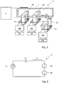
- FIG. 2 shows a schematic view of a part 9 of the electric supply network 1.
- a distribution point 5 is connected to an electric supply line 7 at the floor of the chamber 2.
- the distribution point 5 includes a capacitor that is arranged in series with the electric supply line 7.
- the electric supply line 7 is formed as an electrically conducting wire in a closed loop, so that the line 7 and the capacitor form a resonance circuit, also called LC-circuit or resonance tank.
- the distribution point 5 also includes a converter for converting electrical energy from the electrical source, e.g. a harmonic 50 Hz signal, into electrical energy having a central frequency at the resonance frequency of the resonance tank.
- the converter comprises an adaptive controller according to the invention for controlling energy supplied by an electrical source, viz. from the grid point 3, to the resonance tank connectable to an electric load.
- a magnetic ferrite kernel 10a-c can be shifted around a section of the electric supply line 7 that forms a primary coil.
- a secondary coil 11a-c extends so that a transformer element is formed.
- the secondary coil 11a-c is connected to an output converter 12a-c for converting the resonance signal to a harmonic signal that is suitable for powering the electrical load 13a-c, viz. a 230 V, 50 Hz signal. Since the electrical load 13a-c is inductively connected, there is no danger for an electrical short cut.
- FIG. 3 shows a simple electric scheme of the partial electric supply network 9.
- the resonant power converter including the controller for controlling electrical energy supplied to the resonance tank is represented by a controlled electrical source 14.
- the capacitor C r included in the grid point 5
- the inductor L r representing the coil 7.
- the resonance tank C r , L r is connected in series with electrical loads 13a-b.
- another number of electrical loads might be connected to the resonance tank, e.g. a single load or three loads.
- Figure 4 shows a more detailed electric scheme of the partial electric supply network 9.
- the inductance representing the electric supply line is replaced by a more complex inductor circuit 7 while the controlled electrical source 14 is separated in an electrical source 14a and a converter including a switching stage 14b and the controller for controlling the energy supplied to the resonance tank.
- the switching stage 14b is interconnected between terminals of the electrical source 14a and the resonance tank, respectively.
- the controller drives switching stage 14b switching elements, e.g. semiconductor switches, preferably high power MOSFET switches.
- the output converter 12a-b includes a switching stage that is controlled to generate a desired electrical signal from the resonance signal in the resonance tank.
- the secondary coil 11a is inductively connected to the primary coil via a magnetic coupling 15.
- Figure 5 shows an exemplary inductive connection of a load to the electric supply network 1.
- the coil of the electric supply line 7 has an elongated structure such that an offset between electrically conducting elements of the coil is small with respect to the length of said conducting elements, so that magnetic fields by the individual electrically conducting elements mutually substantially cancel.
- a first section 22 of the coil including conducting elements wherein, during use, electrical currents flow in a particular direction 20 surround a second section 23 of the coil including conducting elements wherein electrical currents flow in an opposite direction 21.
- the electric supply line 7 can be split, e.g. by using a clamp, at least locally, so that the inner section 21 of conducting elements or wires can be pulled locally out of the surrounding outer section 22 of elements.
- the magnetic ferrite kernel 10 can than be moved between the first and second section of the primary coil, so that the magnetic field can be coupled to the secondary coil 11.
- information of energy in the resonance tank is used as a basis for determining an energy amount to be supplied to the resonance tank.
- Figure 6 shows a number of energy plots associated with energy in the resonance tank as a function of time.
- the upper left plot shows the inductive energy E Lr as a function of time t.
- the upper right plot shows the capacitive energy E Cr as a function of time t.
- the lower left plot shows the total energy (inductive energy E Lr added to capacitive energy E Cr ) as a function of time.
- the total energy is mainly constant meeting an ideal situation wherein the amount of energy that is input to the resonance tank is equal to the energy that is output to the loads. Due to a disturbance with respect to the ideal situation, a harmonic ripple is present in the total energy.
- the lower right plot shows the energy E in (dashed line) that is input to the tank and the energy E out (solid line) that is output from the tank.
- the ripple in the total energy is associated with an instantaneous buffer component of the resonance tank energy.
- the instantaneous buffer component might be set strictly positive while the component is also minimized.
- the energy buffer component is used as a basis of information of energy in the resonance tank for the purpose of determining an energy amount to be supplied to the resonance tank.
- a filtered increase of resonance tank energy is integrated and subsequently controlled to a value depending on energy supplied to the resonance tank.
- said value might be related to the supplied energy in a linear or quadratic way.
- a proper relation of said value with the supplied energy can be established.
- the time scale of the filtering process is then different, preferably larger than the time scale of the integrating process, so that a filtered increase of the instantaneous energy buffer component is integrated and related to said value depending on energy supplied to the resonance tank.
- Resonance tank energy information can be determined by measuring at least one physical parameter associated with the resonance tank, e.g. an electrical current and/or an electrical voltage.
- a control objective such as relating a filtered increase of resonance tank energy to a value depending on energy supplied to the resonance tank, can be implemented in various ways, e.g. depending on the converter type and switch stage type.
- PWM pulse width modulation
- PSM phase-shift modulation
- FM frequency modulation
- QC quantum conversion
- control algorithms can be applied, both linear and non-linear.
- a controller based on sliding-mode control theory is explained in more detail below. In order to arrive at a specific controlling method, one or more control objects have to be rewritten as a valid sliding surface.
- the DC input voltage is denoted V in and the control input is denoted by u p .
- the first right hand side term represents the buffer energy in the resonant tank when it is multiplied by the resonant current.
- the second term represents a fraction a of the supplied energy, when also multiplied by the resonant current. Note that both terms originally contained the same resonant current factor i r , which has been left out of the equation, but the energetic origin of the terms is still clear.
- Equation (13) contains the entire dynamics of the closed-loop system.
- Condition (15) simply states that the input current must be larger than load current plus the current through the output filter capacitor.
- the input existence condition is the most interesting one.
- the conditions follow from the fact that the equivalent input control parameter must be between 0 and 1: 0 ⁇ u p,eq ⁇ 1. Setting the equivalent input larger than 0 leads to (16). r r > ⁇ 2 4 ⁇ ⁇ c ⁇ L r
- Equation (16) reflects the idea that the 'filtered' impedance of the averaged resonant tank must be smaller than the loss resistance in order to have enough real damping. In other words, the resonant tank must be able to release its energy fast enough.
- the virtual energy term with ⁇ turns out to be a safety measure. It represents the dynamics of the resonant tank in essence.
- the momentary resonant tank energy can not be viewed as a term completely available (to compensate instantaneously) for the loss energies, because when the tank is empty it must be charged, before it can transfer energy again.
- the control parameter ⁇ is a function of i r (and vice versa) through the sliding surface and the state-space dynamics.
- i r is a function of its own derivative; see (13).
- the resulting first order differential equation is difficult to solve analytically, due to the nonhomogeneous sinusoidal output terms.
- the input sliding surface exists if (19) holds: 600 - ⁇ 2 4 ⁇ 2 ⁇ ⁇ ⁇ 10 5 ⁇ 40 ⁇ 10 - 6 ⁇ ⁇ ⁇ 480 ⁇ ⁇ 600 - 2 ⁇ ⁇ 1 2 > 2 - ⁇ 2 4 ⁇ 2 ⁇ ⁇ ⁇ 10 5 ⁇ 40 ⁇ 10 - 6 ⁇ 480 ⁇ ⁇ 600 - 2 ⁇ ⁇ + 480 ⁇ 0.8 ⁇ ⁇ ⁇ 9.7
- the design solution gives: 1.24 ⁇ ⁇ ⁇ 9.7
- ⁇ represents the fraction of the input energy that is used for the buffer energy in the tank
- the best (i.e., most energy efficient) solution for ⁇ is the minimum allowed value in (20).
- FIG. 7 shows a flow chart of an embodiment of the method according to the invention.
- An adaptive controlling method is used for controlling energy supplied by an electrical source to a resonance tank connectable to an electric load.
- the method comprises the step 100 of determining an energy amount to be supplied based on information of energy in the resonance tank.
- the adaptive controlling method for controlling energy supplied by an electrical source to a resonance tank connectable to an electric load can be performed using dedicated hardware structures, such as FPGA and/or ASIC components. Otherwise, the method can also at least partially be performed using a computer program product comprising instructions for causing a processor of the computer system to perform the above described one or more steps of the method according to the invention. All steps can in principle be performed on a single processor. However it is noted that at least one step can be performed on a separate processor, e.g. the step of minimizing a buffer component of the resonance tank energy.
- the electric supply network according to the invention might in principle be arranged in building rooms having an arbitrary room geometry, such as in a house or in an office.
- the resonance tank can be formed otherwise, e.g. as a capacitor arranged in parallel with the coil of the electric supply line. Further, the electrical loads might be arranged in parallel with the resonance tank.
- the resonance tank can not only be implemented as a first order LC-circuit but also as a higher order circuit including more than two reactive elements.
- one or more electrical loads might be connected to the resonance tank by using an electrically conducting connection without eliminating the operation of the adaptive controller according to the invention.
Landscapes
- Engineering & Computer Science (AREA)
- Power Engineering (AREA)
- Computer Networks & Wireless Communication (AREA)
- Physics & Mathematics (AREA)
- Electromagnetism (AREA)
- Dc-Dc Converters (AREA)
- Ac-Ac Conversion (AREA)
- Physical Or Chemical Processes And Apparatus (AREA)
- Filters And Equalizers (AREA)
Claims (15)
- Adaptives Regelungsverfahren zur Regelung der Energie, die von einer elektrischen Quelle an einen Resonanztank zugeführt wird, der mit einer elektrischen Last verbunden werden kann, das durch Folgendes gekennzeichnet ist:Bestimmen einer zuzuführenden Energiemenge Ein basierend auf Information über die Energie ELC im Resonanztank, und dies durch die Regelung einer integrierten gefilterten Pufferkomponente derart, dass sie proportional zu der an den Resonanztank zugeführten Energiemenge Ein ist; Verwenden eines Bruchteils α der zugeführten Energiemenge Ein für die Pufferenergie im Tank; und Berechnen von α und Bestimmen eines höchsten von unteren Grenzwerten für α aus einerseits:


und andererseits:

wobei Vi die Eingangsgleichspannung bezeichnet, Lr die eingangsseitige Leckinduktivität bezeichnet, rr den primärseitigen Wicklungswiderstand bezeichnet, roj den Ausgangslastwiderstand der Last j bezeichnet, ωc die Resonanzkreisfrequenz bezeichnet, vojref die erforderliche Ausgangsspannung für Last j bezeichnet, Poj die erforderliche Ausgangsleistung für Last j bezeichnet, n die Anzahl der Klemmen für den Anschluss von Lasten bezeichnet, Coj die Kapazität des Ausgangsfilters j parallel zur Last j bezeichnet, vojref die Spannung für Last j bezeichnet, ioj einen Strom durch die Last j bezeichnet. - Verfahren nach Anspruch 1, das außerdem das Berechnen von α umfasst, indem aus Folgendem ein oberer Grenzwert für α bestimmt wird:

- Verfahren nach Anspruch 1 oder 2, bei dem eine Pufferkomponente der Resonanztankenergie derart geregelt wird, dass sie strikt positiv bleibt.
- Verfahren nach Anspruch 2, 3 oder 4, bei dem die Pufferkomponente der Resonanztankenergie im Regelungsvorgang minimiert wird.
- Verfahren nach einem der vorhergehenden Ansprüche 1 bis 4, bei dem ein gefilterter Anstieg der Resonanztankenergie integriert und anschließend auf einen Wert eingestellt wird, der von einer Energiemenge abhängt, die dem Resonanztank zugeführt wird, wobei die Zeitskala des Filtervorgangs bzw. des Integrationsvorgangs unterschiedlich ist.
- Verfahren nach Anspruch 5, bei dem der von der zugeführten Energiemenge abhängige Wert von dieser linear oder quadratisch abhängt.
- Verfahren nach einem der vorhergehenden Ansprüche, das außerdem das Messen wenigstens eines physikalischen Parameters zum Bestimmen von Information über die Resonanztankenergie umfasst.
- Verfahren nach einem der vorhergehenden Ansprüche, das außerdem das Regeln mittels Pulsbreitenmodulation (pulse width modulation, PWM), Phasenmodulation (phase shift modulation, PSM), Frequenzmodulation (FM) und/oder Quantenumwandlungsmodulation (quantum conversion (QC) modulation) umfasst.
- Verfahren nach einem der vorhergehenden Ansprüche, bei dem ein Regelungsschritt basierend auf der Sliding-Mode-Regelungstheorie ausgeführt wird.
- Adaptiver Regler zur Regelung der Energie, die von einer elektrischen Quelle an einen Resonanztank zugeführt wird, der mit einer elektrischen Last verbunden werden kann, dadurch gekennzeichnet, dass der Regler für Folgendes eingerichtet ist:Bestimmen einer zuzuführenden Energiemenge Ein basierend auf Information über die Energie ELC im Resonanztank, und dies durch die Regelung einer integrierten Pufferkomponente derart, dass sie proportional zu der an den Resonanztank zugeführten Energiemenge Ein ist; Verwenden eines Bruchteils α der zugeführten Energiemenge Ein für die Pufferenergie im Tank; und Berechnen von α und Bestimmen eines höchsten von unteren Grenzwerten für α aus einerseits:


und andererseits:

wobei Vi die Eingangsgleichspannung bezeichnet, Lr die eingangsseitige Leckinduktivität bezeichnet, rr den primärseitigen Wicklungswiderstand bezeichnet, roj den Ausgangslastwiderstand der Last j bezeichnet, ωc die Resonanzkreisfrequenz bezeichnet, vojref die erforderliche Ausgangsspannung für Last j bezeichnet, Poj die erforderliche Ausgangsleistung für Last j bezeichnet, n die Anzahl der Klemmen für den Anschluss von Lasten bezeichnet, Coj die Kapazität des Ausgangsfilters j parallel zur Last j bezeichnet, vojref die Spannung für Last j bezeichnet, ioj einen Strom durch die Last j bezeichnet. - Adaptiver Regler nach Anspruch 10, wobei der Regler dafür eingerichtet ist, eine Schaltstufe anzusteuern, die zwischen Anschlüssen der elektrischen Quelle bzw. des Resonanztanks angeschlossen ist.
- Stromversorgungsnetz, das einen adaptiven Regler nach Anspruch 11 und den daran angeschlossenen Resonanztank umfasst.
- Stromversorgungsnetz nach Anspruch 12, wobei der Resonanztank eine LC-Schaltung umfasst und wobei eine Spule der LC-Schaltung induktiv mit der elektrischen Last gekoppelt werden kann.
- Stromversorgungsnetz nach Anspruch 13, wobei die Spule mit einer höheren Zahl elektrischer Lasten induktiv gekoppelt werden kann.
- Stromversorgungsnetz nach Anspruch 13 oder 14, wobei die Spule eine längliche Form hat und ein Versatz zwischen elektrisch leitenden Elementen der Spule in Bezug auf die Länge der leitenden Elemente derart ist, dass Magnetfelder der einzelnen elektrisch leitenden Elemente sich im Wesentlichen gegenseitig auslöschen.
Applications Claiming Priority (2)
| Application Number | Priority Date | Filing Date | Title |
|---|---|---|---|
| NL2003450A NL2003450C2 (en) | 2009-09-08 | 2009-09-08 | An adaptive controlling method, an adaptive controller and a computer program product. |
| PCT/NL2010/050570 WO2011031143A1 (en) | 2009-09-08 | 2010-09-08 | Adaptive control method and adaptive controller for controlling energy supplied to a resonant tank |
Publications (2)
| Publication Number | Publication Date |
|---|---|
| EP2476178A1 EP2476178A1 (de) | 2012-07-18 |
| EP2476178B1 true EP2476178B1 (de) | 2014-11-05 |
Family
ID=42041539
Family Applications (1)
| Application Number | Title | Priority Date | Filing Date |
|---|---|---|---|
| EP20100757318 Active EP2476178B1 (de) | 2009-09-08 | 2010-09-08 | Adaptives steuerverfahren und adaptives steuergerät zur steuerung der an einen resonanten tank gelieferten energie |
Country Status (7)
| Country | Link |
|---|---|
| US (1) | US9130479B2 (de) |
| EP (1) | EP2476178B1 (de) |
| KR (1) | KR101773923B1 (de) |
| CN (1) | CN102725934B (de) |
| BR (1) | BR112012005253A2 (de) |
| NL (1) | NL2003450C2 (de) |
| WO (1) | WO2011031143A1 (de) |
Families Citing this family (3)
| Publication number | Priority date | Publication date | Assignee | Title |
|---|---|---|---|---|
| NL2010330C2 (en) * | 2013-02-19 | 2014-08-21 | Optimos Apto B V | Device to predict zero current or peak current, in particular in an inductive electrical energy transfer system. |
| NL2016810B1 (en) | 2016-05-23 | 2017-11-30 | Optimos Apto B V | A method, a controller and a network |
| TWI774608B (zh) * | 2021-11-10 | 2022-08-11 | 台達電子工業股份有限公司 | 轉換模組的輔助電源電路、平衡電路與供電系統 |
-
2009
- 2009-09-08 NL NL2003450A patent/NL2003450C2/en not_active IP Right Cessation
-
2010
- 2010-09-08 US US13/394,829 patent/US9130479B2/en not_active Expired - Fee Related
- 2010-09-08 BR BR112012005253A patent/BR112012005253A2/pt not_active Application Discontinuation
- 2010-09-08 CN CN201080047373.4A patent/CN102725934B/zh not_active Expired - Fee Related
- 2010-09-08 WO PCT/NL2010/050570 patent/WO2011031143A1/en not_active Ceased
- 2010-09-08 KR KR1020127009022A patent/KR101773923B1/ko not_active Expired - Fee Related
- 2010-09-08 EP EP20100757318 patent/EP2476178B1/de active Active
Also Published As
| Publication number | Publication date |
|---|---|
| US9130479B2 (en) | 2015-09-08 |
| CN102725934A (zh) | 2012-10-10 |
| CN102725934B (zh) | 2015-05-20 |
| WO2011031143A1 (en) | 2011-03-17 |
| KR101773923B1 (ko) | 2017-09-12 |
| EP2476178A1 (de) | 2012-07-18 |
| BR112012005253A2 (pt) | 2016-03-15 |
| NL2003450C2 (en) | 2011-03-09 |
| US20120326519A1 (en) | 2012-12-27 |
| KR20120066034A (ko) | 2012-06-21 |
Similar Documents
| Publication | Publication Date | Title |
|---|---|---|
| Azer et al. | Generalized state space average model for multi-phase interleaved buck, boost and buck-boost DC-DC converters: Transient, steady-state and switching dynamics | |
| EP3479465B1 (de) | Umrichter mit ein-phasen und drei-phasen betriebsmodus | |
| Bowden et al. | Switched-mode load impedance synthesis to parametrically tune electromagnetic vibration energy harvesters | |
| Chen et al. | Design and implementation of the low computational burden phase‐shifted modulation for DC–DC modular multilevel converter | |
| Zahid et al. | Damping impact on dynamic analysis of LLC resonant converter | |
| Abdelsalam et al. | Single‐stage, single‐phase, ac–dc buck–boost converter for low‐voltage applications | |
| Mo et al. | Model predictive control for Z-source power converter | |
| US9130479B2 (en) | Adaptive control method and adaptive controller for controlling energy supplied to a resonant tank | |
| Pantic et al. | Inductive power transfer by means of multiple frequencies in the magnetic link | |
| Kumar et al. | Harmonic inclusion and accurate modeling and performance analysis of the ipt topologies under varying operating conditions | |
| BC et al. | Higher order output filter design for grid connected power converters | |
| Wu et al. | Efficient power-transfer capability analysis of the TET system using the equivalent small parameter method | |
| Marin-Hurtado et al. | Calculation of core losses in magnetic materials under nonsinusoidal excitation | |
| Rivera et al. | A simple predictive voltage control method with unity displacement power factor for four-leg indirect matrix converters | |
| Keeling et al. | Unity power factor inductive power transfer pick-up for high power applications | |
| Wang et al. | Inductance and power losses analysis of an arm inductor for a modular multilevel converter | |
| Lu et al. | LQG control of capacitive power transfer system | |
| Nitheesh et al. | Modeling and analysis of high gain pole point inductor-based series resonant dual active bridge converter | |
| Johnson et al. | GaN based inverter with high conversion ratio and sinusoidal output for motor drive applications stress analysis | |
| Miiura et al. | Voltage control of inductive contactless power transfer system with coaxial coreless transformer for DC power distribution | |
| EP3465870B1 (de) | Verfahren, steuergerät und netzwerk | |
| Gawande et al. | State feedback‐based capacitor voltage equalisation scheme in distribution static compensator for load compensation | |
| Fischer et al. | Current Control for a Multiphase Interleaved-Switched Inverter Using Field Oriented Coordinates | |
| Arun et al. | Extended harmonic analysis of wireless charging systems | |
| Korotyeyev et al. | Steady‐state modelling of basic unipolar PWM AC line matrix‐reactance choppers |
Legal Events
| Date | Code | Title | Description |
|---|---|---|---|
| PUAI | Public reference made under article 153(3) epc to a published international application that has entered the european phase |
Free format text: ORIGINAL CODE: 0009012 |
|
| 17P | Request for examination filed |
Effective date: 20120405 |
|
| AK | Designated contracting states |
Kind code of ref document: A1 Designated state(s): AL AT BE BG CH CY CZ DE DK EE ES FI FR GB GR HR HU IE IS IT LI LT LU LV MC MK MT NL NO PL PT RO SE SI SK SM TR |
|
| DAX | Request for extension of the european patent (deleted) | ||
| 17Q | First examination report despatched |
Effective date: 20130613 |
|
| REG | Reference to a national code |
Ref country code: DE Ref legal event code: R079 Ref document number: 602010019991 Country of ref document: DE Free format text: PREVIOUS MAIN CLASS: H02J0005000000 Ipc: H02M0007480000 |
|
| GRAP | Despatch of communication of intention to grant a patent |
Free format text: ORIGINAL CODE: EPIDOSNIGR1 |
|
| RIC1 | Information provided on ipc code assigned before grant |
Ipc: H02M 7/48 20070101AFI20140313BHEP Ipc: H02M 7/5387 20070101ALI20140313BHEP Ipc: H02J 5/00 20060101ALI20140313BHEP |
|
| INTG | Intention to grant announced |
Effective date: 20140410 |
|
| GRAS | Grant fee paid |
Free format text: ORIGINAL CODE: EPIDOSNIGR3 |
|
| GRAA | (expected) grant |
Free format text: ORIGINAL CODE: 0009210 |
|
| AK | Designated contracting states |
Kind code of ref document: B1 Designated state(s): AL AT BE BG CH CY CZ DE DK EE ES FI FR GB GR HR HU IE IS IT LI LT LU LV MC MK MT NL NO PL PT RO SE SI SK SM TR |
|
| REG | Reference to a national code |
Ref country code: GB Ref legal event code: FG4D |
|
| REG | Reference to a national code |
Ref country code: CH Ref legal event code: NV Representative=s name: ARNOLD AND SIEDSMA AG, CH Ref country code: CH Ref legal event code: EP |
|
| REG | Reference to a national code |
Ref country code: AT Ref legal event code: REF Ref document number: 695046 Country of ref document: AT Kind code of ref document: T Effective date: 20141115 |
|
| REG | Reference to a national code |
Ref country code: IE Ref legal event code: FG4D |
|
| REG | Reference to a national code |
Ref country code: DE Ref legal event code: R096 Ref document number: 602010019991 Country of ref document: DE Effective date: 20141218 |
|
| REG | Reference to a national code |
Ref country code: SE Ref legal event code: TRGR |
|
| REG | Reference to a national code |
Ref country code: NL Ref legal event code: T3 |
|
| REG | Reference to a national code |
Ref country code: AT Ref legal event code: MK05 Ref document number: 695046 Country of ref document: AT Kind code of ref document: T Effective date: 20141105 |
|
| REG | Reference to a national code |
Ref country code: LT Ref legal event code: MG4D |
|
| PG25 | Lapsed in a contracting state [announced via postgrant information from national office to epo] |
Ref country code: FI Free format text: LAPSE BECAUSE OF FAILURE TO SUBMIT A TRANSLATION OF THE DESCRIPTION OR TO PAY THE FEE WITHIN THE PRESCRIBED TIME-LIMIT Effective date: 20141105 Ref country code: LT Free format text: LAPSE BECAUSE OF FAILURE TO SUBMIT A TRANSLATION OF THE DESCRIPTION OR TO PAY THE FEE WITHIN THE PRESCRIBED TIME-LIMIT Effective date: 20141105 Ref country code: ES Free format text: LAPSE BECAUSE OF FAILURE TO SUBMIT A TRANSLATION OF THE DESCRIPTION OR TO PAY THE FEE WITHIN THE PRESCRIBED TIME-LIMIT Effective date: 20141105 Ref country code: NO Free format text: LAPSE BECAUSE OF FAILURE TO SUBMIT A TRANSLATION OF THE DESCRIPTION OR TO PAY THE FEE WITHIN THE PRESCRIBED TIME-LIMIT Effective date: 20150205 Ref country code: IS Free format text: LAPSE BECAUSE OF FAILURE TO SUBMIT A TRANSLATION OF THE DESCRIPTION OR TO PAY THE FEE WITHIN THE PRESCRIBED TIME-LIMIT Effective date: 20150305 Ref country code: PT Free format text: LAPSE BECAUSE OF FAILURE TO SUBMIT A TRANSLATION OF THE DESCRIPTION OR TO PAY THE FEE WITHIN THE PRESCRIBED TIME-LIMIT Effective date: 20150305 |
|
| PG25 | Lapsed in a contracting state [announced via postgrant information from national office to epo] |
Ref country code: PL Free format text: LAPSE BECAUSE OF FAILURE TO SUBMIT A TRANSLATION OF THE DESCRIPTION OR TO PAY THE FEE WITHIN THE PRESCRIBED TIME-LIMIT Effective date: 20141105 Ref country code: LV Free format text: LAPSE BECAUSE OF FAILURE TO SUBMIT A TRANSLATION OF THE DESCRIPTION OR TO PAY THE FEE WITHIN THE PRESCRIBED TIME-LIMIT Effective date: 20141105 Ref country code: GR Free format text: LAPSE BECAUSE OF FAILURE TO SUBMIT A TRANSLATION OF THE DESCRIPTION OR TO PAY THE FEE WITHIN THE PRESCRIBED TIME-LIMIT Effective date: 20150206 Ref country code: AT Free format text: LAPSE BECAUSE OF FAILURE TO SUBMIT A TRANSLATION OF THE DESCRIPTION OR TO PAY THE FEE WITHIN THE PRESCRIBED TIME-LIMIT Effective date: 20141105 Ref country code: CY Free format text: LAPSE BECAUSE OF FAILURE TO SUBMIT A TRANSLATION OF THE DESCRIPTION OR TO PAY THE FEE WITHIN THE PRESCRIBED TIME-LIMIT Effective date: 20141105 Ref country code: HR Free format text: LAPSE BECAUSE OF FAILURE TO SUBMIT A TRANSLATION OF THE DESCRIPTION OR TO PAY THE FEE WITHIN THE PRESCRIBED TIME-LIMIT Effective date: 20141105 |
|
| PG25 | Lapsed in a contracting state [announced via postgrant information from national office to epo] |
Ref country code: EE Free format text: LAPSE BECAUSE OF FAILURE TO SUBMIT A TRANSLATION OF THE DESCRIPTION OR TO PAY THE FEE WITHIN THE PRESCRIBED TIME-LIMIT Effective date: 20141105 Ref country code: DK Free format text: LAPSE BECAUSE OF FAILURE TO SUBMIT A TRANSLATION OF THE DESCRIPTION OR TO PAY THE FEE WITHIN THE PRESCRIBED TIME-LIMIT Effective date: 20141105 Ref country code: CZ Free format text: LAPSE BECAUSE OF FAILURE TO SUBMIT A TRANSLATION OF THE DESCRIPTION OR TO PAY THE FEE WITHIN THE PRESCRIBED TIME-LIMIT Effective date: 20141105 Ref country code: SK Free format text: LAPSE BECAUSE OF FAILURE TO SUBMIT A TRANSLATION OF THE DESCRIPTION OR TO PAY THE FEE WITHIN THE PRESCRIBED TIME-LIMIT Effective date: 20141105 |
|
| REG | Reference to a national code |
Ref country code: DE Ref legal event code: R097 Ref document number: 602010019991 Country of ref document: DE |
|
| PLBE | No opposition filed within time limit |
Free format text: ORIGINAL CODE: 0009261 |
|
| STAA | Information on the status of an ep patent application or granted ep patent |
Free format text: STATUS: NO OPPOSITION FILED WITHIN TIME LIMIT |
|
| REG | Reference to a national code |
Ref country code: FR Ref legal event code: PLFP Year of fee payment: 6 |
|
| 26N | No opposition filed |
Effective date: 20150806 |
|
| PG25 | Lapsed in a contracting state [announced via postgrant information from national office to epo] |
Ref country code: SI Free format text: LAPSE BECAUSE OF FAILURE TO SUBMIT A TRANSLATION OF THE DESCRIPTION OR TO PAY THE FEE WITHIN THE PRESCRIBED TIME-LIMIT Effective date: 20141105 |
|
| PG25 | Lapsed in a contracting state [announced via postgrant information from national office to epo] |
Ref country code: MC Free format text: LAPSE BECAUSE OF FAILURE TO SUBMIT A TRANSLATION OF THE DESCRIPTION OR TO PAY THE FEE WITHIN THE PRESCRIBED TIME-LIMIT Effective date: 20141105 Ref country code: LU Free format text: LAPSE BECAUSE OF FAILURE TO SUBMIT A TRANSLATION OF THE DESCRIPTION OR TO PAY THE FEE WITHIN THE PRESCRIBED TIME-LIMIT Effective date: 20150908 |
|
| PG25 | Lapsed in a contracting state [announced via postgrant information from national office to epo] |
Ref country code: RO Free format text: LAPSE BECAUSE OF FAILURE TO SUBMIT A TRANSLATION OF THE DESCRIPTION OR TO PAY THE FEE WITHIN THE PRESCRIBED TIME-LIMIT Effective date: 20141105 |
|
| REG | Reference to a national code |
Ref country code: IE Ref legal event code: MM4A |
|
| PG25 | Lapsed in a contracting state [announced via postgrant information from national office to epo] |
Ref country code: IE Free format text: LAPSE BECAUSE OF NON-PAYMENT OF DUE FEES Effective date: 20150908 |
|
| REG | Reference to a national code |
Ref country code: FR Ref legal event code: PLFP Year of fee payment: 7 |
|
| PG25 | Lapsed in a contracting state [announced via postgrant information from national office to epo] |
Ref country code: MT Free format text: LAPSE BECAUSE OF FAILURE TO SUBMIT A TRANSLATION OF THE DESCRIPTION OR TO PAY THE FEE WITHIN THE PRESCRIBED TIME-LIMIT Effective date: 20141105 |
|
| PG25 | Lapsed in a contracting state [announced via postgrant information from national office to epo] |
Ref country code: BG Free format text: LAPSE BECAUSE OF FAILURE TO SUBMIT A TRANSLATION OF THE DESCRIPTION OR TO PAY THE FEE WITHIN THE PRESCRIBED TIME-LIMIT Effective date: 20141105 Ref country code: SM Free format text: LAPSE BECAUSE OF FAILURE TO SUBMIT A TRANSLATION OF THE DESCRIPTION OR TO PAY THE FEE WITHIN THE PRESCRIBED TIME-LIMIT Effective date: 20141105 Ref country code: HU Free format text: LAPSE BECAUSE OF FAILURE TO SUBMIT A TRANSLATION OF THE DESCRIPTION OR TO PAY THE FEE WITHIN THE PRESCRIBED TIME-LIMIT; INVALID AB INITIO Effective date: 20100908 |
|
| PG25 | Lapsed in a contracting state [announced via postgrant information from national office to epo] |
Ref country code: TR Free format text: LAPSE BECAUSE OF FAILURE TO SUBMIT A TRANSLATION OF THE DESCRIPTION OR TO PAY THE FEE WITHIN THE PRESCRIBED TIME-LIMIT Effective date: 20141105 |
|
| REG | Reference to a national code |
Ref country code: FR Ref legal event code: PLFP Year of fee payment: 8 |
|
| PG25 | Lapsed in a contracting state [announced via postgrant information from national office to epo] |
Ref country code: BE Free format text: LAPSE BECAUSE OF FAILURE TO SUBMIT A TRANSLATION OF THE DESCRIPTION OR TO PAY THE FEE WITHIN THE PRESCRIBED TIME-LIMIT Effective date: 20141105 |
|
| PG25 | Lapsed in a contracting state [announced via postgrant information from national office to epo] |
Ref country code: MK Free format text: LAPSE BECAUSE OF FAILURE TO SUBMIT A TRANSLATION OF THE DESCRIPTION OR TO PAY THE FEE WITHIN THE PRESCRIBED TIME-LIMIT Effective date: 20141105 |
|
| PG25 | Lapsed in a contracting state [announced via postgrant information from national office to epo] |
Ref country code: AL Free format text: LAPSE BECAUSE OF FAILURE TO SUBMIT A TRANSLATION OF THE DESCRIPTION OR TO PAY THE FEE WITHIN THE PRESCRIBED TIME-LIMIT Effective date: 20141105 |
|
| PGFP | Annual fee paid to national office [announced via postgrant information from national office to epo] |
Ref country code: IT Payment date: 20230915 Year of fee payment: 14 Ref country code: GB Payment date: 20230915 Year of fee payment: 14 |
|
| PGFP | Annual fee paid to national office [announced via postgrant information from national office to epo] |
Ref country code: SE Payment date: 20230915 Year of fee payment: 14 Ref country code: FR Payment date: 20230915 Year of fee payment: 14 Ref country code: DE Payment date: 20230915 Year of fee payment: 14 |
|
| PGFP | Annual fee paid to national office [announced via postgrant information from national office to epo] |
Ref country code: CH Payment date: 20231001 Year of fee payment: 14 |
|
| REG | Reference to a national code |
Ref country code: DE Ref legal event code: R119 Ref document number: 602010019991 Country of ref document: DE |
|
| REG | Reference to a national code |
Ref country code: SE Ref legal event code: EUG |
|
| REG | Reference to a national code |
Ref country code: CH Ref legal event code: PL |
|
| GBPC | Gb: european patent ceased through non-payment of renewal fee |
Effective date: 20240908 |
|
| PG25 | Lapsed in a contracting state [announced via postgrant information from national office to epo] |
Ref country code: DE Free format text: LAPSE BECAUSE OF NON-PAYMENT OF DUE FEES Effective date: 20250401 |
|
| PG25 | Lapsed in a contracting state [announced via postgrant information from national office to epo] |
Ref country code: GB Free format text: LAPSE BECAUSE OF NON-PAYMENT OF DUE FEES Effective date: 20240908 |
|
| PG25 | Lapsed in a contracting state [announced via postgrant information from national office to epo] |
Ref country code: IT Free format text: LAPSE BECAUSE OF NON-PAYMENT OF DUE FEES Effective date: 20240908 |
|
| PG25 | Lapsed in a contracting state [announced via postgrant information from national office to epo] |
Ref country code: FR Free format text: LAPSE BECAUSE OF NON-PAYMENT OF DUE FEES Effective date: 20240930 |
|
| PG25 | Lapsed in a contracting state [announced via postgrant information from national office to epo] |
Ref country code: CH Free format text: LAPSE BECAUSE OF NON-PAYMENT OF DUE FEES Effective date: 20240930 |
|
| PG25 | Lapsed in a contracting state [announced via postgrant information from national office to epo] |
Ref country code: SE Free format text: LAPSE BECAUSE OF NON-PAYMENT OF DUE FEES Effective date: 20240909 |
|
| PGFP | Annual fee paid to national office [announced via postgrant information from national office to epo] |
Ref country code: NL Payment date: 20250915 Year of fee payment: 16 |