EP2476129B1 - Treatment and adhesive for microporous membranes - Google Patents
Treatment and adhesive for microporous membranes Download PDFInfo
- Publication number
- EP2476129B1 EP2476129B1 EP10778411.8A EP10778411A EP2476129B1 EP 2476129 B1 EP2476129 B1 EP 2476129B1 EP 10778411 A EP10778411 A EP 10778411A EP 2476129 B1 EP2476129 B1 EP 2476129B1
- Authority
- EP
- European Patent Office
- Prior art keywords
- adhesive
- electrode
- separator
- solvent
- pvdf
- Prior art date
- Legal status (The legal status is an assumption and is not a legal conclusion. Google has not performed a legal analysis and makes no representation as to the accuracy of the status listed.)
- Active
Links
Images
Classifications
-
- C—CHEMISTRY; METALLURGY
- C09—DYES; PAINTS; POLISHES; NATURAL RESINS; ADHESIVES; COMPOSITIONS NOT OTHERWISE PROVIDED FOR; APPLICATIONS OF MATERIALS NOT OTHERWISE PROVIDED FOR
- C09J—ADHESIVES; NON-MECHANICAL ASPECTS OF ADHESIVE PROCESSES IN GENERAL; ADHESIVE PROCESSES NOT PROVIDED FOR ELSEWHERE; USE OF MATERIALS AS ADHESIVES
- C09J127/00—Adhesives based on homopolymers or copolymers of compounds having one or more unsaturated aliphatic radicals, each having only one carbon-to-carbon double bond, and at least one being terminated by a halogen; Adhesives based on derivatives of such polymers
- C09J127/02—Adhesives based on homopolymers or copolymers of compounds having one or more unsaturated aliphatic radicals, each having only one carbon-to-carbon double bond, and at least one being terminated by a halogen; Adhesives based on derivatives of such polymers not modified by chemical after-treatment
- C09J127/12—Adhesives based on homopolymers or copolymers of compounds having one or more unsaturated aliphatic radicals, each having only one carbon-to-carbon double bond, and at least one being terminated by a halogen; Adhesives based on derivatives of such polymers not modified by chemical after-treatment containing fluorine atoms
- C09J127/16—Homopolymers or copolymers of vinylidene fluoride
-
- B—PERFORMING OPERATIONS; TRANSPORTING
- B32—LAYERED PRODUCTS
- B32B—LAYERED PRODUCTS, i.e. PRODUCTS BUILT-UP OF STRATA OF FLAT OR NON-FLAT, e.g. CELLULAR OR HONEYCOMB, FORM
- B32B15/00—Layered products comprising a layer of metal
- B32B15/04—Layered products comprising a layer of metal comprising metal as the main or only constituent of a layer, which is next to another layer of the same or of a different material
- B32B15/08—Layered products comprising a layer of metal comprising metal as the main or only constituent of a layer, which is next to another layer of the same or of a different material of synthetic resin
- B32B15/082—Layered products comprising a layer of metal comprising metal as the main or only constituent of a layer, which is next to another layer of the same or of a different material of synthetic resin comprising vinyl resins; comprising acrylic resins
-
- B—PERFORMING OPERATIONS; TRANSPORTING
- B32—LAYERED PRODUCTS
- B32B—LAYERED PRODUCTS, i.e. PRODUCTS BUILT-UP OF STRATA OF FLAT OR NON-FLAT, e.g. CELLULAR OR HONEYCOMB, FORM
- B32B15/00—Layered products comprising a layer of metal
- B32B15/20—Layered products comprising a layer of metal comprising aluminium or copper
-
- B—PERFORMING OPERATIONS; TRANSPORTING
- B32—LAYERED PRODUCTS
- B32B—LAYERED PRODUCTS, i.e. PRODUCTS BUILT-UP OF STRATA OF FLAT OR NON-FLAT, e.g. CELLULAR OR HONEYCOMB, FORM
- B32B27/00—Layered products comprising a layer of synthetic resin
- B32B27/30—Layered products comprising a layer of synthetic resin comprising vinyl (co)polymers; comprising acrylic (co)polymers
- B32B27/304—Layered products comprising a layer of synthetic resin comprising vinyl (co)polymers; comprising acrylic (co)polymers comprising vinyl halide (co)polymers, e.g. PVC, PVDC, PVF, PVDF
-
- B—PERFORMING OPERATIONS; TRANSPORTING
- B32—LAYERED PRODUCTS
- B32B—LAYERED PRODUCTS, i.e. PRODUCTS BUILT-UP OF STRATA OF FLAT OR NON-FLAT, e.g. CELLULAR OR HONEYCOMB, FORM
- B32B5/00—Layered products characterised by the non- homogeneity or physical structure, i.e. comprising a fibrous, filamentary, particulate or foam layer; Layered products characterised by having a layer differing constitutionally or physically in different parts
- B32B5/18—Layered products characterised by the non- homogeneity or physical structure, i.e. comprising a fibrous, filamentary, particulate or foam layer; Layered products characterised by having a layer differing constitutionally or physically in different parts characterised by features of a layer of foamed material
-
- B—PERFORMING OPERATIONS; TRANSPORTING
- B32—LAYERED PRODUCTS
- B32B—LAYERED PRODUCTS, i.e. PRODUCTS BUILT-UP OF STRATA OF FLAT OR NON-FLAT, e.g. CELLULAR OR HONEYCOMB, FORM
- B32B7/00—Layered products characterised by the relation between layers; Layered products characterised by the relative orientation of features between layers, or by the relative values of a measurable parameter between layers, i.e. products comprising layers having different physical, chemical or physicochemical properties; Layered products characterised by the interconnection of layers
- B32B7/04—Interconnection of layers
- B32B7/12—Interconnection of layers using interposed adhesives or interposed materials with bonding properties
- B32B7/14—Interconnection of layers using interposed adhesives or interposed materials with bonding properties applied in spaced arrangements, e.g. in stripes
-
- H—ELECTRICITY
- H01—ELECTRIC ELEMENTS
- H01G—CAPACITORS; CAPACITORS, RECTIFIERS, DETECTORS, SWITCHING DEVICES OR LIGHT-SENSITIVE DEVICES, OF THE ELECTROLYTIC TYPE
- H01G11/00—Hybrid capacitors, i.e. capacitors having different positive and negative electrodes; Electric double-layer [EDL] capacitors; Processes for the manufacture thereof or of parts thereof
- H01G11/52—Separators
-
- H—ELECTRICITY
- H01—ELECTRIC ELEMENTS
- H01G—CAPACITORS; CAPACITORS, RECTIFIERS, DETECTORS, SWITCHING DEVICES OR LIGHT-SENSITIVE DEVICES, OF THE ELECTROLYTIC TYPE
- H01G11/00—Hybrid capacitors, i.e. capacitors having different positive and negative electrodes; Electric double-layer [EDL] capacitors; Processes for the manufacture thereof or of parts thereof
- H01G11/78—Cases; Housings; Encapsulations; Mountings
- H01G11/82—Fixing or assembling a capacitive element in a housing, e.g. mounting electrodes, current collectors or terminals in containers or encapsulations
-
- H—ELECTRICITY
- H01—ELECTRIC ELEMENTS
- H01G—CAPACITORS; CAPACITORS, RECTIFIERS, DETECTORS, SWITCHING DEVICES OR LIGHT-SENSITIVE DEVICES, OF THE ELECTROLYTIC TYPE
- H01G11/00—Hybrid capacitors, i.e. capacitors having different positive and negative electrodes; Electric double-layer [EDL] capacitors; Processes for the manufacture thereof or of parts thereof
- H01G11/84—Processes for the manufacture of hybrid or EDL capacitors, or components thereof
-
- H—ELECTRICITY
- H01—ELECTRIC ELEMENTS
- H01G—CAPACITORS; CAPACITORS, RECTIFIERS, DETECTORS, SWITCHING DEVICES OR LIGHT-SENSITIVE DEVICES, OF THE ELECTROLYTIC TYPE
- H01G9/00—Electrolytic capacitors, rectifiers, detectors, switching devices, light-sensitive or temperature-sensitive devices; Processes of their manufacture
- H01G9/004—Details
- H01G9/02—Diaphragms; Separators
-
- H—ELECTRICITY
- H01—ELECTRIC ELEMENTS
- H01M—PROCESSES OR MEANS, e.g. BATTERIES, FOR THE DIRECT CONVERSION OF CHEMICAL ENERGY INTO ELECTRICAL ENERGY
- H01M10/00—Secondary cells; Manufacture thereof
- H01M10/05—Accumulators with non-aqueous electrolyte
- H01M10/058—Construction or manufacture
-
- H—ELECTRICITY
- H01—ELECTRIC ELEMENTS
- H01M—PROCESSES OR MEANS, e.g. BATTERIES, FOR THE DIRECT CONVERSION OF CHEMICAL ENERGY INTO ELECTRICAL ENERGY
- H01M50/00—Constructional details or processes of manufacture of the non-active parts of electrochemical cells other than fuel cells, e.g. hybrid cells
- H01M50/40—Separators; Membranes; Diaphragms; Spacing elements inside cells
- H01M50/409—Separators, membranes or diaphragms characterised by the material
- H01M50/411—Organic material
- H01M50/414—Synthetic resins, e.g. thermoplastics or thermosetting resins
- H01M50/426—Fluorocarbon polymers
-
- H—ELECTRICITY
- H01—ELECTRIC ELEMENTS
- H01M—PROCESSES OR MEANS, e.g. BATTERIES, FOR THE DIRECT CONVERSION OF CHEMICAL ENERGY INTO ELECTRICAL ENERGY
- H01M50/00—Constructional details or processes of manufacture of the non-active parts of electrochemical cells other than fuel cells, e.g. hybrid cells
- H01M50/40—Separators; Membranes; Diaphragms; Spacing elements inside cells
- H01M50/46—Separators, membranes or diaphragms characterised by their combination with electrodes
-
- B—PERFORMING OPERATIONS; TRANSPORTING
- B32—LAYERED PRODUCTS
- B32B—LAYERED PRODUCTS, i.e. PRODUCTS BUILT-UP OF STRATA OF FLAT OR NON-FLAT, e.g. CELLULAR OR HONEYCOMB, FORM
- B32B2250/00—Layers arrangement
- B32B2250/42—Alternating layers, e.g. ABAB(C), AABBAABB(C)
-
- B—PERFORMING OPERATIONS; TRANSPORTING
- B32—LAYERED PRODUCTS
- B32B—LAYERED PRODUCTS, i.e. PRODUCTS BUILT-UP OF STRATA OF FLAT OR NON-FLAT, e.g. CELLULAR OR HONEYCOMB, FORM
- B32B2307/00—Properties of the layers or laminate
- B32B2307/50—Properties of the layers or laminate having particular mechanical properties
-
- B—PERFORMING OPERATIONS; TRANSPORTING
- B32—LAYERED PRODUCTS
- B32B—LAYERED PRODUCTS, i.e. PRODUCTS BUILT-UP OF STRATA OF FLAT OR NON-FLAT, e.g. CELLULAR OR HONEYCOMB, FORM
- B32B2457/00—Electrical equipment
- B32B2457/10—Batteries
-
- B—PERFORMING OPERATIONS; TRANSPORTING
- B32—LAYERED PRODUCTS
- B32B—LAYERED PRODUCTS, i.e. PRODUCTS BUILT-UP OF STRATA OF FLAT OR NON-FLAT, e.g. CELLULAR OR HONEYCOMB, FORM
- B32B2457/00—Electrical equipment
- B32B2457/16—Capacitors
-
- H—ELECTRICITY
- H01—ELECTRIC ELEMENTS
- H01M—PROCESSES OR MEANS, e.g. BATTERIES, FOR THE DIRECT CONVERSION OF CHEMICAL ENERGY INTO ELECTRICAL ENERGY
- H01M10/00—Secondary cells; Manufacture thereof
- H01M10/05—Accumulators with non-aqueous electrolyte
- H01M10/052—Li-accumulators
-
- H—ELECTRICITY
- H01—ELECTRIC ELEMENTS
- H01M—PROCESSES OR MEANS, e.g. BATTERIES, FOR THE DIRECT CONVERSION OF CHEMICAL ENERGY INTO ELECTRICAL ENERGY
- H01M10/00—Secondary cells; Manufacture thereof
- H01M10/05—Accumulators with non-aqueous electrolyte
- H01M10/052—Li-accumulators
- H01M10/0525—Rocking-chair batteries, i.e. batteries with lithium insertion or intercalation in both electrodes; Lithium-ion batteries
-
- H—ELECTRICITY
- H01—ELECTRIC ELEMENTS
- H01M—PROCESSES OR MEANS, e.g. BATTERIES, FOR THE DIRECT CONVERSION OF CHEMICAL ENERGY INTO ELECTRICAL ENERGY
- H01M10/00—Secondary cells; Manufacture thereof
- H01M10/05—Accumulators with non-aqueous electrolyte
- H01M10/056—Accumulators with non-aqueous electrolyte characterised by the materials used as electrolytes, e.g. mixed inorganic/organic electrolytes
- H01M10/0564—Accumulators with non-aqueous electrolyte characterised by the materials used as electrolytes, e.g. mixed inorganic/organic electrolytes the electrolyte being constituted of organic materials only
- H01M10/0565—Polymeric materials, e.g. gel-type or solid-type
-
- H—ELECTRICITY
- H01—ELECTRIC ELEMENTS
- H01M—PROCESSES OR MEANS, e.g. BATTERIES, FOR THE DIRECT CONVERSION OF CHEMICAL ENERGY INTO ELECTRICAL ENERGY
- H01M10/00—Secondary cells; Manufacture thereof
- H01M10/06—Lead-acid accumulators
-
- H—ELECTRICITY
- H01—ELECTRIC ELEMENTS
- H01M—PROCESSES OR MEANS, e.g. BATTERIES, FOR THE DIRECT CONVERSION OF CHEMICAL ENERGY INTO ELECTRICAL ENERGY
- H01M50/00—Constructional details or processes of manufacture of the non-active parts of electrochemical cells other than fuel cells, e.g. hybrid cells
- H01M50/40—Separators; Membranes; Diaphragms; Spacing elements inside cells
- H01M50/46—Separators, membranes or diaphragms characterised by their combination with electrodes
- H01M50/461—Separators, membranes or diaphragms characterised by their combination with electrodes with adhesive layers between electrodes and separators
-
- H—ELECTRICITY
- H01—ELECTRIC ELEMENTS
- H01M—PROCESSES OR MEANS, e.g. BATTERIES, FOR THE DIRECT CONVERSION OF CHEMICAL ENERGY INTO ELECTRICAL ENERGY
- H01M50/00—Constructional details or processes of manufacture of the non-active parts of electrochemical cells other than fuel cells, e.g. hybrid cells
- H01M50/40—Separators; Membranes; Diaphragms; Spacing elements inside cells
- H01M50/489—Separators, membranes, diaphragms or spacing elements inside the cells, characterised by their physical properties, e.g. swelling degree, hydrophilicity or shut down properties
- H01M50/491—Porosity
-
- Y—GENERAL TAGGING OF NEW TECHNOLOGICAL DEVELOPMENTS; GENERAL TAGGING OF CROSS-SECTIONAL TECHNOLOGIES SPANNING OVER SEVERAL SECTIONS OF THE IPC; TECHNICAL SUBJECTS COVERED BY FORMER USPC CROSS-REFERENCE ART COLLECTIONS [XRACs] AND DIGESTS
- Y02—TECHNOLOGIES OR APPLICATIONS FOR MITIGATION OR ADAPTATION AGAINST CLIMATE CHANGE
- Y02E—REDUCTION OF GREENHOUSE GAS [GHG] EMISSIONS, RELATED TO ENERGY GENERATION, TRANSMISSION OR DISTRIBUTION
- Y02E60/00—Enabling technologies; Technologies with a potential or indirect contribution to GHG emissions mitigation
- Y02E60/10—Energy storage using batteries
-
- Y—GENERAL TAGGING OF NEW TECHNOLOGICAL DEVELOPMENTS; GENERAL TAGGING OF CROSS-SECTIONAL TECHNOLOGIES SPANNING OVER SEVERAL SECTIONS OF THE IPC; TECHNICAL SUBJECTS COVERED BY FORMER USPC CROSS-REFERENCE ART COLLECTIONS [XRACs] AND DIGESTS
- Y02—TECHNOLOGIES OR APPLICATIONS FOR MITIGATION OR ADAPTATION AGAINST CLIMATE CHANGE
- Y02E—REDUCTION OF GREENHOUSE GAS [GHG] EMISSIONS, RELATED TO ENERGY GENERATION, TRANSMISSION OR DISTRIBUTION
- Y02E60/00—Enabling technologies; Technologies with a potential or indirect contribution to GHG emissions mitigation
- Y02E60/13—Energy storage using capacitors
-
- Y—GENERAL TAGGING OF NEW TECHNOLOGICAL DEVELOPMENTS; GENERAL TAGGING OF CROSS-SECTIONAL TECHNOLOGIES SPANNING OVER SEVERAL SECTIONS OF THE IPC; TECHNICAL SUBJECTS COVERED BY FORMER USPC CROSS-REFERENCE ART COLLECTIONS [XRACs] AND DIGESTS
- Y02—TECHNOLOGIES OR APPLICATIONS FOR MITIGATION OR ADAPTATION AGAINST CLIMATE CHANGE
- Y02P—CLIMATE CHANGE MITIGATION TECHNOLOGIES IN THE PRODUCTION OR PROCESSING OF GOODS
- Y02P70/00—Climate change mitigation technologies in the production process for final industrial or consumer products
- Y02P70/50—Manufacturing or production processes characterised by the final manufactured product
Definitions
- Microporous membranes are used in various electrochemical and energy storage devices such as super capacitors and batteries to separate electrodes. Batteries or super capacitors may be constructed by layering the microporous separator between an anode and cathode, then infiltrating the device with an electrolyte.
- electrochemical cell shall refer to any type of energy storage cell unless otherwise noted.
- microporous membranes may be manufactured using PVDF or other polymers. Because of the microporous nature, the membranes may be very fragile. Holes or tears in the membrane may lead to shorts between the electrodes, rendering a battery cell or an entire electrochemical device unusable. Blockages within the membranes may decrease performance by not allowing ions in the electrolyte to pass from one electrode to another.
- Some batteries are constructed as multiple layers of electrodes and separators.
- the batteries may be wound into a cylinder, wound about a flat plate, or constructed as flat sandwiches of multiple layers.
- WO 2009/026467 discloses an electrode/separator assembly.
- EP 0 892 454 discloses a polymeric separator.
- US 5,778,515 discloses an electrode layer bonded to a separator layer.
- EP 1 482 578 discloses a battery separator comprising a microporous membrane and a coating on it.
- WO 02/50929 discloses a battery cell separator.
- WO 2005/123599 discloses a highly microporous polymer.
- US 5,811,205 discloses an electrode containing a non-aqueous liquid electrolyte.
- WO 99/45604 discloses a method of preparing a non-aqueous electrochemical cell.
- the present invention relates to a method comprising:
- An electrochemical cell has a PVDF microporous membrane that is adhesively bonded to electrodes.
- the adhesive is a mixture of a solvent and non-solvent that causes the PVDF membrane to become tacky and adhere to an electrode without collapsing.
- An adhesively bonded cell may be constructed using multiple layers of adhesively bonded membranes and electrodes. In some embodiments, the adhesive solution may be used as a sizing to prepare electrodes for bonding.
- An electrochemical cell may be constructed from a PVDF microporous separator bonded to electrodes using an adhesive comprising a solvent capable of dissolving the PVDF, but with enough non-solvent to prevent the destruction of the microporous separator.
- the adhesive may cause the PVDF separator to become tacky when wet and to adhere to an electrode after curing.
- An electrochemical cell such as a battery, capacitor, or supercapacitor, may have anode and cathode electrodes separated by a separator film.
- the more closely the electrodes are spaced the higher the performance of the cell.
- they may short. A short may render the cell inoperable, as well as cause a fire or other destruction when a short occurs while the cell is energized.
- PVDF Polyvinylidene Fluoride
- a solvent and mixed with a second liquid which may be a non-solvent and have a higher surface tension and higher boiling point than the solvent.
- a second liquid which may be a non-solvent and have a higher surface tension and higher boiling point than the solvent.
- Such a solution may be processed by raising the temperature until the solvent begins to evaporate, causing the polymer to gel, after which the temperature may be raised until the second liquid may be removed.
- the PVDF may be dissolved into a solvent and then cast while submersed in a water bath. The polymer may gel during the casting process.
- the layers of electrodes and separators may be bonded together to keep the layers from separating or for the cell to expand.
- a casing or container may apply some compressive force between the layers, either by mechanical compression or by applying a vacuum to the inside of the cell.
- the adhesive especially when containing polymer, may be suitable for repairing pinholes in a microporous membrane composed of the same polymer.
- the adhesive may be applied by a dropper or other applicator and may allow the membrane to be repaired while leaving a protective layer of polymer.
- the adhesive may also be used as a sizing to fill voids or correct surface imperfections. When the sizing may be applied to the microporous membrane, the sizing may fill pinholes. When the sizing may be applied to an electrode, the surface of the electrode may be prepared for bonding.
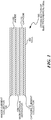
- Figure 1 is a diagram of an embodiment 100, showing an electrochemical cell 102 in cross-section.
- the cell 102 may be a typical construction of a battery or supercapacitor.
- the cell 102 may be a lithium ion battery, lithium polymer battery, lead acid battery, or other type of electrochemical cell.
- An anode current collector 104 may be a conductive film that may conduct a positive charge from the anode 106.
- the anode 106 may be active material, such as carbon in a conventional lithium-ion battery chemistry.
- a microporous separator 108 may separate the anode 106 from a cathode 110.
- the cathode 110 may be a second active material, such as a metal oxide in a conventional lithium-ion battery chemistry.
- the separator 108 may be constructed of PVDF using various methods to produce a microporous film.
- the film may have small holes that may be interconnected to allow an electrolyte to permeate the separator 108.
- ions may pass between the anode and cathode during charging and discharging events.
- the electrolyte may contain a lithium salt in an organic solvent.
- the separator 108 may have a thickness on the order of 25 to 50 microns and have porosities of 60 to 85%. Within the separator 108, small webs of 2 to 4 microns thick may form the structure of the microporous material.
- the selection of an adhesive may be sensitive to the performance of the separator. If the separator dissolves substantially, the polymer within the separator may collapse and restrict ion conduction between the electrodes.
- An adhesive contains both a solvent and non-solvent.
- the solvent may be a strong or weak solvent that may be further diluted with the non-solvent.
- the solvent partially dissolves the PVDF material to the point of becoming tacky but not to the point of collapsing. The tackiness may be sufficient to effectively bond the PVDF separator to an electrode.
- suitable solvents may include methyl formate, acetone (2-propanone), methyl acetate, tetrahydrofuran, ethyl acetate, methyl ethyl ketone (2-butanone), acetonitrile, dimethyl carbonate, 1,2-dioxane, toluene, acetone, and methyl isobutyl ketone.
- Acetone in particular, may be effective as a room temperature adhesive.
- Acetone is a very effective solvent of PVDF at higher temperatures, such as 55 degrees C., but is only a poor solvent at room temperature.
- the adhesive or a variant of the adhesive may be used as a sizing on the electrodes prior to adhesive bonding.
- the sizing may improve bonding between the electrode and separator when the adhesive is applied.
- the sizing may be applied to the electrode and allowed to dry or cure. After curing, the adhesive bonding process may be performed.
- the adhesive may contain up to 6% by weight of the same polymer as the separator.
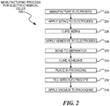
- Figure 2 is a flowchart illustration of an embodiment 200 showing a method for manufacturing an electrochemical cell.
- Embodiment 200 illustrates a simplified method for assembling an electrochemical cell.
- Embodiment 200 illustrates a method for creating a single cell, but the same concepts and steps may be expanded to include electrochemical devices with multiple cells.
- the electrodes may be manufactured in block 202.
- an electrode may be manufactured on an aluminum, copper or other metallic film where the metallic film may be a current collector for the cell.
- Sizing may be applied to the electrodes in block 204 and cured in block 206.
- the sizing may be the same or similar formulation as the adhesive used to bond the separator to the electrode.
- the adhesive may be applied to the electrodes in block 208 and the electrodes may be bonded to the separator in block 210.
- the adhesive may be cured in block 212, placed in a packaging or container in block 214, and filled with electrolyte in block 216.
- the assembly may have a vacuum applied in block 218 to remove any air and allow the electrolyte to fully permeate the separator.
- the bonding operation may be performed in many different manners.
- the adhesive may be applied to the electrode and then the separator may be mated to the electrode.
- the adhesive may be applied by spraying, dipping, pouring, wiping, or any other method.
- the adhesive may be applied to coat the entire surface, or at least a majority of the surface of an electrode. In other embodiments, the adhesive may be selectively applied to the electrode.
- the adhesive may be applied in a series of dots or spots that cover 50% or less of the surface area of an electrode. In some cases, the adhesive may be applied to less than 25%, 20%, 15%, 10%, 5%, 2%, or 1% of the bonding area of the electrode.
- the adhesive may be applied to the separator.
- the adhesive may be sprayed or otherwise applied to the bonding surfaces of the separator.
- the separator may be submerged or fully infiltrated with the adhesive.
- the adhesive may be applied selectively to the separator and may cover a percentage of the surface area of the separator.
- the adhesive may be cured by applying heat, vacuum, or other processes. In some cases, the adhesive may be reactivated by applying additional adhesive after an electrode and separator stack is formed.
- the packaging for an electrochemical cell may vary in different applications.
- the packaging may be a flexible pouch to which a vacuum may be applied.
- Other embodiments may use metal cans of various shapes, including cylindrical, rectangular, or other shapes.
- the packaging may apply mechanical pressure to the electrochemical cell to compact the layers of electrodes and separators.
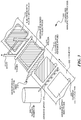
- Figure 3 is a diagram illustration of an embodiment 300 showing a simplified assembly process for an electrode and separator subassembly.
- Embodiment 300 illustrates a conveyor 302 on which electrode subassemblies may be manufactured.
- Embodiment 300 is a schematic illustration of a simple production line where electrode subassemblies may be manufactured in a continuous fashion.
- an electrode 304 may be placed on a conveyor 302.
- the electrode may be constructed with a current collector that may be exposed as a current collector tab 306.
- the remaining surface of the electrode 304 may contain the active electrode material corresponding with the anode or cathode of an electrochemical cell.
- the electrodes and separators may be sheet goods that may be layered to create an electrochemical cell.
- Each component of the cell may have a surface that may bond or contact another component.
- the sheet goods may be processed using sheet processing mechanisms, and the sheet goods may be roll goods or individual sheets of material.
- the sheet goods may be layered using many repeating stacks of layers to create multiple cells in a single device.
- the layers may be subsequently formed, such as winding into a cylinder, winding onto a flat mandrel, or otherwise folded or wound.
- the layers may be stacked and assembled and used in a flat configuration.
- An adhesive spray 308 may dispense adhesive from a reservoir 310 to form an electrode with adhesive applied 312. In some cases, the adhesive spray 308 may apply adhesive over the active portions of the electrode but may not apply adhesive on the current collector tab of the electrode.
- the adhesive spray 308 illustrates a method whereby the full surface of the electrode may be coated with the adhesive. Other methods may include dipping, pouring, calendaring, and others.
- the adhesive may be applied in a method whereby the full surface of the electrode is not covered.
- a pattern of application may be used so that 50% or less of the available bonding surface area of the electrode may have adhesive applied.
- Various mechanisms may be used to apply adhesive in a selective fashion. Such methods may include screen printing, selective application using spraying, or other methods.
- a microporous separator feed mechanism 314 may supply a microporous separator in a sheet form.
- the separator may pass between rollers 316 and 318 to apply separator to the electrode to create a separator bonded to an electrode 320.
- the separator may be cut so that the waste 322 may be removed, yielding an electrode/separator subassembly 324.
- Electrode subassemblies 324 may be stacked together, alternating between anodes and cathodes.
- the current collector tabs may be joined together, electrolyte added, and the electrochemical device may be packaged for use.
- the non-solvent may be formed from two liquids, one of which being a high surface energy liquid and the other being a lower surface energy liquid.
- polymer up to 6% by weight was added to the adhesive. Some embodiments may contain up to 1%, 2%, 4%, 8%, or 10% polymer by weight.
- Tables A and B illustrate various solvents and non-solvents, respectively, for producing adhesives.
- Tables A and B include boiling point and surface energy parameters for the given liquids.
- TABLE A Solvent Liquid Normal Boiling Point deg. C Surface Energy, dynes/cm methyl formate 31.7 24.4 acetone (2-propanone) 56 23.5 methyl acetate 56.9 24.7 tetrahydrofuran 66 26.4 ethyl acetate 77 23.4 methyl ethyl ketone (2-butanone) 80 24 acetonitrile 81 29 dimethyl carbonate 90 31.9 1,2-dioxane 100 32 Toluene 110 28.4 methyl isobutyl ketone 116 23.4 TABLE B Non-solvent Liquid Normal Boiling Point, deg.
- a separator film was made of a blend of two PVDF homopolymers and a PVDF-HFP copolymer.
- the membrane was 80% porous as measured by ingress of isopropanol and by density.
- a separator treatment solution was made using 3 parts (by weight) acetone and 1 part isopropanol.
- the separator membrane was wetted with this treatment solution and then placed between a commercial anode and cathode for construction of a single-cell lithium-ion battery.
- the assembly was assembled without clamping and solvents were allowed to evaporate from the assembly.
- the cell was filled with 1 M, LiPF6, EC/EMC electrolyte, which easily wetted the components and displaced air from the system without use of vacuum, a particular attribute with this type of separator.
- This cell had a discharge capacity of 11.9 mAh and a 12C rating of 1.6 mAh.
- Example 1 The procedure of Example 1 was repeated except that the separator film was treated at 40 degrees Celsius with a treatment solution consisting of: acetone 82.75%, isopropanol 12.5%, water 1.75%, and a blend of three PVDF polymers and copolymers mixture 3%.
- a treatment solution consisting of: acetone 82.75%, isopropanol 12.5%, water 1.75%, and a blend of three PVDF polymers and copolymers mixture 3%.
- a single cell battery was made with a separator with this treatment and two commercial electrodes.
- the cell was vacuum-dried at 40° C. and the components were well-bonded together without any damage to the porous separator. Its electrical performance was comparable to that of a clamped, unbonded cell using the same separator and electrodes and was far superior at high C rates to a commercial separator.
- Three samples of a separator film of the lot of Example 1 was treated with 3 parts 3:1 acetone:isopropanol to 1 part by weight of a 90.5% acetone, 3.5% water, and 6% PVDF polymers and copolymer at 25 degrees Celsius.
- a separator film of the lot of Example 1 was used for assembly of single cell batteries.
- the electrodes were treated with a "treatment solution” consisting of acetone, isopropanol, water, and the PVDF mixture.
- the separator was brought into contact with the electrodes at room temperature while the electrode surfaces were wet.
- the structure was then dried at 25 degrees Celsius by vacuum drying.
- a separator film of the lot of Example 1 was used for assembly of single cell batteries.
- the electrodes were coated lightly with a "treatment solution” consisting of: acetone, isopropanol, water, and PVDF mixture.
- the treatment was allowed to dry and the electrodes were then assembled with 25 degrees Celsius by vacuum drying.
- the cell performance characteristics were excellent.
- the cells were filled with 1 M, LiPF6, EC/EMC electrolyte, which easily wetted the components and displaced air from the system without use of vacuum - a particular attribute with this type of separator, in contrast to separators made of polyolefin plastics.
- Dimethyl carbonate is one of the solvents commonly used for the electrolyte in lithium ion batteries. A small residue of dimethyl carbonate remaining within the battery may be tolerable, and the methanol of this mixture is known to evaporate quickly.
Landscapes
- Engineering & Computer Science (AREA)
- Power Engineering (AREA)
- Chemical & Material Sciences (AREA)
- Microelectronics & Electronic Packaging (AREA)
- Electrochemistry (AREA)
- Chemical Kinetics & Catalysis (AREA)
- General Chemical & Material Sciences (AREA)
- Manufacturing & Machinery (AREA)
- Organic Chemistry (AREA)
- Cell Separators (AREA)
- Secondary Cells (AREA)
- Battery Electrode And Active Subsutance (AREA)
- Electric Double-Layer Capacitors Or The Like (AREA)
Description
- Microporous membranes are used in various electrochemical and energy storage devices such as super capacitors and batteries to separate electrodes. Batteries or super capacitors may be constructed by layering the microporous separator between an anode and cathode, then infiltrating the device with an electrolyte. For convenience, throughout this document the term "electrochemical cell" shall refer to any type of energy storage cell unless otherwise noted.
- In many cases, microporous membranes may be manufactured using PVDF or other polymers. Because of the microporous nature, the membranes may be very fragile. Holes or tears in the membrane may lead to shorts between the electrodes, rendering a battery cell or an entire electrochemical device unusable. Blockages within the membranes may decrease performance by not allowing ions in the electrolyte to pass from one electrode to another.
- Some batteries are constructed as multiple layers of electrodes and separators. The batteries may be wound into a cylinder, wound about a flat plate, or constructed as flat sandwiches of multiple layers.
WO 2009/026467 discloses an electrode/separator assembly.EP 0 892 454 discloses a polymeric separator.US 5,778,515 discloses an electrode layer bonded to a separator layer.EP 1 482 578 discloses a battery separator comprising a microporous membrane and a coating on it.WO 02/50929 WO 2005/123599 discloses a highly microporous polymer.US 5,811,205 discloses an electrode containing a non-aqueous liquid electrolyte.WO 99/45604 - In a first aspect, the present invention relates to a method comprising:
- receiving a first electrode for an electrochemical cell;
- receiving a microporous film comprising PVDF;
- using an adhesive to bond said microporous film to said first electrode to form a first subassembly, said adhesive comprising:
- a solvent capable of dissolving said PVDF of said microporous film;
- a non-solvent having a surface energy higher than a surface energy of said solvent; and
- PVDF;
- assembling said first subassembly to a second electrode to form said electrochemical cell,
- wherein prior to said bonding:
- said adhesive is applied to said first electrode; and
- said adhesive is allowed to dry.
- An electrochemical cell has a PVDF microporous membrane that is adhesively bonded to electrodes. The adhesive is a mixture of a solvent and non-solvent that causes the PVDF membrane to become tacky and adhere to an electrode without collapsing. An adhesively bonded cell may be constructed using multiple layers of adhesively bonded membranes and electrodes. In some embodiments, the adhesive solution may be used as a sizing to prepare electrodes for bonding.
- This Summary is provided to introduce a selection of concepts in a simplified form that are further described below in the Detailed Description. This Summary is not intended to identify key features or essential features of the claimed subject matter, nor is it intended to be used to limit the scope of the claimed subject matter.
- In the drawings,
-
FIGURE 1 is a diagram illustration of an embodiment showing a cross-sectional view of an electrochemical cell. -
FIGURE 2 is a flowchart illustration of an embodiment showing a method for constructing an electrochemical cell. -
FIGURE 3 is a flowchart illustration of an embodiment showing a method for assembling a subassembly for an electrochemical cell. - An electrochemical cell may be constructed from a PVDF microporous separator bonded to electrodes using an adhesive comprising a solvent capable of dissolving the PVDF, but with enough non-solvent to prevent the destruction of the microporous separator. The adhesive may cause the PVDF separator to become tacky when wet and to adhere to an electrode after curing.
- An electrochemical cell, such as a battery, capacitor, or supercapacitor, may have anode and cathode electrodes separated by a separator film. In general, the more closely the electrodes are spaced, the higher the performance of the cell. However, when the electrodes touch each other, they may short. A short may render the cell inoperable, as well as cause a fire or other destruction when a short occurs while the cell is energized.
- PVDF (Polyvinylidene Fluoride) is a polymer that may be formed into microporous membranes using different methods. In one method, PVDF may be dissolved in a solvent and mixed with a second liquid which may be a non-solvent and have a higher surface tension and higher boiling point than the solvent. Such a solution may be processed by raising the temperature until the solvent begins to evaporate, causing the polymer to gel, after which the temperature may be raised until the second liquid may be removed. In a second manufacturing method, the PVDF may be dissolved into a solvent and then cast while submersed in a water bath. The polymer may gel during the casting process.
- When creating an electrochemical cell, the layers of electrodes and separators may be bonded together to keep the layers from separating or for the cell to expand. In some embodiments, a casing or container may apply some compressive force between the layers, either by mechanical compression or by applying a vacuum to the inside of the cell.
- The adhesive, especially when containing polymer, may be suitable for repairing pinholes in a microporous membrane composed of the same polymer. The adhesive may be applied by a dropper or other applicator and may allow the membrane to be repaired while leaving a protective layer of polymer. The adhesive may also be used as a sizing to fill voids or correct surface imperfections. When the sizing may be applied to the microporous membrane, the sizing may fill pinholes. When the sizing may be applied to an electrode, the surface of the electrode may be prepared for bonding.
- Throughout this specification, like reference numbers signify the same elements throughout the description of the figures.
- When elements are referred to as being "connected" or "coupled," the elements can be directly connected or coupled together or one or more intervening elements may also be present. In contrast, when elements are referred to as being "directly connected" or "directly coupled," there are no intervening elements present.
-
Figure 1 is a diagram of anembodiment 100, showing anelectrochemical cell 102 in cross-section. - The
cell 102 may be a typical construction of a battery or supercapacitor. Thecell 102 may be a lithium ion battery, lithium polymer battery, lead acid battery, or other type of electrochemical cell. - An anode current collector 104 may be a conductive film that may conduct a positive charge from the
anode 106. In a typical construction, theanode 106 may be active material, such as carbon in a conventional lithium-ion battery chemistry. - A microporous separator 108 may separate the
anode 106 from acathode 110. Thecathode 110 may be a second active material, such as a metal oxide in a conventional lithium-ion battery chemistry. - The separator 108 may be constructed of PVDF using various methods to produce a microporous film. The film may have small holes that may be interconnected to allow an electrolyte to permeate the separator 108. Within the electrolyte, ions may pass between the anode and cathode during charging and discharging events. The electrolyte may contain a lithium salt in an organic solvent.
- The separator 108 may have a thickness on the order of 25 to 50 microns and have porosities of 60 to 85%. Within the separator 108, small webs of 2 to 4 microns thick may form the structure of the microporous material.
- Because the separator 108 may have very small structural walls, the selection of an adhesive may be sensitive to the performance of the separator. If the separator dissolves substantially, the polymer within the separator may collapse and restrict ion conduction between the electrodes.
- An adhesive contains both a solvent and non-solvent. The solvent may be a strong or weak solvent that may be further diluted with the non-solvent. The solvent partially dissolves the PVDF material to the point of becoming tacky but not to the point of collapsing. The tackiness may be sufficient to effectively bond the PVDF separator to an electrode.
- Examples of suitable solvents may include methyl formate, acetone (2-propanone), methyl acetate, tetrahydrofuran, ethyl acetate, methyl ethyl ketone (2-butanone), acetonitrile, dimethyl carbonate, 1,2-dioxane, toluene, acetone, and methyl isobutyl ketone.
- Acetone, in particular, may be effective as a room temperature adhesive. Acetone is a very effective solvent of PVDF at higher temperatures, such as 55 degrees C., but is only a poor solvent at room temperature.
- The adhesive or a variant of the adhesive may be used as a sizing on the electrodes prior to adhesive bonding. The sizing may improve bonding between the electrode and separator when the adhesive is applied. The sizing may be applied to the electrode and allowed to dry or cure. After curing, the adhesive bonding process may be performed.
- In some embodiments, the adhesive may contain up to 6% by weight of the same polymer as the separator.
-
Figure 2 is a flowchart illustration of anembodiment 200 showing a method for manufacturing an electrochemical cell. - Other embodiments may use different sequencing, additional or fewer steps, and different nomenclature or terminology to accomplish similar functions. In some embodiments, various operations or sets of operations may be performed in parallel with other operations, either in a synchronous or asynchronous manner. The steps selected here were chosen to illustrate some principles of operations in a simplified form.
-
Embodiment 200 illustrates a simplified method for assembling an electrochemical cell.Embodiment 200 illustrates a method for creating a single cell, but the same concepts and steps may be expanded to include electrochemical devices with multiple cells. - The electrodes may be manufactured in
block 202. In many embodiments, an electrode may be manufactured on an aluminum, copper or other metallic film where the metallic film may be a current collector for the cell. - Sizing may be applied to the electrodes in
block 204 and cured inblock 206. The sizing may be the same or similar formulation as the adhesive used to bond the separator to the electrode. - The adhesive may be applied to the electrodes in
block 208 and the electrodes may be bonded to the separator inblock 210. The adhesive may be cured inblock 212, placed in a packaging or container inblock 214, and filled with electrolyte inblock 216. The assembly may have a vacuum applied inblock 218 to remove any air and allow the electrolyte to fully permeate the separator. - The bonding operation may be performed in many different manners. In some cases, the adhesive may be applied to the electrode and then the separator may be mated to the electrode. The adhesive may be applied by spraying, dipping, pouring, wiping, or any other method.
- In some embodiments, the adhesive may be applied to coat the entire surface, or at least a majority of the surface of an electrode. In other embodiments, the adhesive may be selectively applied to the electrode.
- For example, the adhesive may be applied in a series of dots or spots that cover 50% or less of the surface area of an electrode. In some cases, the adhesive may be applied to less than 25%, 20%, 15%, 10%, 5%, 2%, or 1% of the bonding area of the electrode.
- In some embodiments, the adhesive may be applied to the separator. The adhesive may be sprayed or otherwise applied to the bonding surfaces of the separator. In some cases, the separator may be submerged or fully infiltrated with the adhesive. When the adhesive is applied to the separator, the adhesive may be applied selectively to the separator and may cover a percentage of the surface area of the separator.
- The adhesive may be cured by applying heat, vacuum, or other processes. In some cases, the adhesive may be reactivated by applying additional adhesive after an electrode and separator stack is formed.
- The packaging for an electrochemical cell may vary in different applications. In some embodiments, the packaging may be a flexible pouch to which a vacuum may be applied. Other embodiments may use metal cans of various shapes, including cylindrical, rectangular, or other shapes. In some embodiments, the packaging may apply mechanical pressure to the electrochemical cell to compact the layers of electrodes and separators.
-
Figure 3 is a diagram illustration of anembodiment 300 showing a simplified assembly process for an electrode and separator subassembly. -
Embodiment 300 illustrates aconveyor 302 on which electrode subassemblies may be manufactured.Embodiment 300 is a schematic illustration of a simple production line where electrode subassemblies may be manufactured in a continuous fashion. - At a first stage of the assembly process, an
electrode 304 may be placed on aconveyor 302. The electrode may be constructed with a current collector that may be exposed as acurrent collector tab 306. The remaining surface of theelectrode 304 may contain the active electrode material corresponding with the anode or cathode of an electrochemical cell. - In many embodiments, the electrodes and separators may be sheet goods that may be layered to create an electrochemical cell. Each component of the cell may have a surface that may bond or contact another component. The sheet goods may be processed using sheet processing mechanisms, and the sheet goods may be roll goods or individual sheets of material.
- In some embodiments, the sheet goods may be layered using many repeating stacks of layers to create multiple cells in a single device. The layers may be subsequently formed, such as winding into a cylinder, winding onto a flat mandrel, or otherwise folded or wound. In other embodiments, the layers may be stacked and assembled and used in a flat configuration.
- An
adhesive spray 308 may dispense adhesive from areservoir 310 to form an electrode with adhesive applied 312. In some cases, theadhesive spray 308 may apply adhesive over the active portions of the electrode but may not apply adhesive on the current collector tab of the electrode. - The
adhesive spray 308 illustrates a method whereby the full surface of the electrode may be coated with the adhesive. Other methods may include dipping, pouring, calendaring, and others. - In some embodiments, the adhesive may be applied in a method whereby the full surface of the electrode is not covered. For example, a pattern of application may be used so that 50% or less of the available bonding surface area of the electrode may have adhesive applied.
- Various mechanisms may be used to apply adhesive in a selective fashion. Such methods may include screen printing, selective application using spraying, or other methods.
- After the electrode has adhesive applied, a microporous separator feed mechanism 314 may supply a microporous separator in a sheet form. The separator may pass between
rollers electrode 320. The separator may be cut so that thewaste 322 may be removed, yielding an electrode/separator subassembly 324. - In order to manufacture an electrochemical cell,
several electrode subassemblies 324 may be stacked together, alternating between anodes and cathodes. The current collector tabs may be joined together, electrolyte added, and the electrochemical device may be packaged for use. - In several experiments, detailed below, different adhesive formulations were evaluated. In general, favorable results were obtained with a weak solvent combined with a non-solvent, where the non-solvent had a surface energy higher than the solvent. In some embodiments, the non-solvent may be formed from two liquids, one of which being a high surface energy liquid and the other being a lower surface energy liquid.
- In some experiments, up to 6% by weight of polymer was added to the adhesive. Some embodiments may contain up to 1%, 2%, 4%, 8%, or 10% polymer by weight.
- Tables A and B illustrate various solvents and non-solvents, respectively, for producing adhesives. Tables A and B include boiling point and surface energy parameters for the given liquids.
TABLE A Solvent Liquid Normal Boiling Point, deg. C Surface Energy, dynes/cm methyl formate 31.7 24.4 acetone (2-propanone) 56 23.5 methyl acetate 56.9 24.7 tetrahydrofuran 66 26.4 ethyl acetate 77 23.4 methyl ethyl ketone (2-butanone) 80 24 acetonitrile 81 29 dimethyl carbonate 90 31.9 1,2- dioxane 100 32 Toluene 110 28.4 methyl isobutyl ketone 116 23.4 TABLE B Non-solvent Liquid Normal Boiling Point, deg. C Surface Energy, dynes/cm nitromethane 101 37 bromo benzene 156 37 formic acid 100 38 pyridine 114 38 ethylene bromide 131 38 3-furaldehyde 144 40 bromine 59 42 tribromomethane 150 42 quinoline 24 43 nitric acid (69%) 86 43 water 100 72.5 - The following examples are test results from various configurations of bonding PVDF separators to electrodes.
- A separator film was made of a blend of two PVDF homopolymers and a PVDF-HFP copolymer. The membrane was 80% porous as measured by ingress of isopropanol and by density.
- A separator treatment solution was made using 3 parts (by weight) acetone and 1 part isopropanol. The separator membrane was wetted with this treatment solution and then placed between a commercial anode and cathode for construction of a single-cell lithium-ion battery. The assembly was assembled without clamping and solvents were allowed to evaporate from the assembly.
- The cell was filled with 1 M, LiPF6, EC/EMC electrolyte, which easily wetted the components and displaced air from the system without use of vacuum, a particular attribute with this type of separator.
- This cell had a discharge capacity of 11.9 mAh and a 12C rating of 1.6 mAh.
- The procedure of Example 1 was repeated except that the separator film was treated at 40 degrees Celsius with a treatment solution consisting of: acetone 82.75%, isopropanol 12.5%, water 1.75%, and a blend of three PVDF polymers and copolymers mixture 3%.
- A single cell battery was made with a separator with this treatment and two commercial electrodes. The cell was vacuum-dried at 40° C. and the components were well-bonded together without any damage to the porous separator. Its electrical performance was comparable to that of a clamped, unbonded cell using the same separator and electrodes and was far superior at high C rates to a commercial separator.
- Three samples of a separator film of the lot of Example 1 was treated with 3 parts 3:1 acetone:isopropanol to 1 part by weight of a 90.5% acetone, 3.5% water, and 6% PVDF polymers and copolymer at 25 degrees Celsius.
- Three single cell batteries were made with these separators and two commercial electrodes each. The cells were vacuum dried at 25 degrees Celsius. The components were well bonded together without any damage to the porous separator.
- The electrical performance of each of the three cells was comparable to that of a clamped, unbonded cell using the same separator and electrodes.
- A separator film of the lot of Example 1 was used for assembly of single cell batteries. In this example, the electrodes were treated with a "treatment solution" consisting of acetone, isopropanol, water, and the PVDF mixture. The separator was brought into contact with the electrodes at room temperature while the electrode surfaces were wet. The structure was then dried at 25 degrees Celsius by vacuum drying.
- The electrical characteristics of this cell were excellent and were almost as good as a clamped cell prepared from the same components.
- A separator film of the lot of Example 1 was used for assembly of single cell batteries. In this instance, the electrodes were coated lightly with a "treatment solution" consisting of: acetone, isopropanol, water, and PVDF mixture.
- The treatment was allowed to dry and the electrodes were then assembled with 25 degrees Celsius by vacuum drying.
- The cell performance characteristics were excellent.
- In all of the examples, the cells were filled with 1 M, LiPF6, EC/EMC electrolyte, which easily wetted the components and displaced air from the system without use of vacuum - a particular attribute with this type of separator, in contrast to separators made of polyolefin plastics.
- Various solutions of acetone and a mixture of 70% isopropanol and 30% water were prepared for treatment of porous PVDF separators. When the separators were wetted and then placed in contact with one another the following results were obtained:
Weight % acetone/70 % isopropanol Effect 100/0 complete dissolution of polymer 98/2 good tack bond 96.2/3.8 " 94.3/5.7 " 92.6/7.4 slight tack bond 88.9/11.1 no bond - This test showed that a limited range of solvent/non-solvent is appropriate for solvent activation of the PVDF to accomplish an adhesive bond.
- Various solutions of acetone with 100% isopropanol were prepared for treatment of porous PVDF separators. When the separators were wetted and then placed in contact with one another, the following results were obtained:
Weight percent acetone/isopropanol Effects 97.6/2.4 complete dissolution of polymer 93.5/6.5 slight tack bond 85.1/14.9 very slight tack bond 81.6/18.4 no bond - Various solutions of acetone with water were prepared for treatment of porous PVDF separators. When the separators were wetted and then placed in contact with one another, the following results were obtained:
Weight percent acetone/water Effects 97.6/2.4 slight tack bond 95.2/4.8 good tack bond 90.9/9.1 no bond - Various solutions of dimethyl carbonate and methanol were prepared for treatment of porous PVDF separators. When the separators were wetted and then placed in contact with one another, the following results were obtained:
Weight percent DMC/methanol Effects 97.6/2.4 very good tack bond 88.9/11/1 good tack bond 80.0/20.0 " - Dimethyl carbonate is one of the solvents commonly used for the electrolyte in lithium ion batteries. A small residue of dimethyl carbonate remaining within the battery may be tolerable, and the methanol of this mixture is known to evaporate quickly.
- The foregoing description of the subject matter has been presented for purposes of illustration and description. It is not intended to be exhaustive or to limit the subject matter of the appended claims to the precise form disclosed, and other modifications and variations may be possible in light of the above teachings within the scope of the appended claims. The embodiment was chosen and described in order to best explain the principles of the invention and its practical application to thereby enable others skilled in the art to best utilize the invention in various embodiments and various modifications as are suited to the particular use contemplated. It is intended that the appended claims be construed to include other alternative embodiments except insofar as limited by the prior art.
Claims (9)
- A method comprising:receiving a first electrode for an electrochemical cell;receiving a microporous film comprising PVDF;using an adhesive to bond said microporous film to said first electrode to form a first subassembly, said adhesive comprising:a solvent capable of dissolving said PVDF of said microporous film;a non-solvent having a surface energy higher than a surface energy of said solvent; andPVDF;assembling said first subassembly to a second electrode to form said electrochemical cell,wherein prior to said bonding:said adhesive is applied to said first electrode; andsaid adhesive is allowed to dry.
- The method of claim 1, said adhesive further comprising acetone.
- The method of claim 1, said adhesive being applied by spraying, preferably to said electrode.
- The method of claim 1, said adhesive being applied in a discontinuous manner to an interface area between said first electrode and said microporous film, said discontinuous manner preferably comprising a dot pattern.
- The method of claim 4, said discontinuous manner covering less than 50% of said interface area, and preferably covering less than 2% of said interface area.
- The method of claim 1 further comprising:
adding a liquid electrolyte to said electrochemical cell, said liquid electrolyte preferably comprising said non-solvent. - The method of claim 1 further comprising:
applying a vacuum to said electrochemical cell. - The method of claim 1, said first subassembly being assembled to said second electrode by using said adhesive.
- The method of claim 8, said first subassembly being assembled to said second electrode prior to drying said adhesive used to form said first subassembly.
Applications Claiming Priority (2)
| Application Number | Priority Date | Filing Date | Title |
|---|---|---|---|
| US18012809P | 2009-05-20 | 2009-05-20 | |
| PCT/US2010/035647 WO2010135573A2 (en) | 2009-05-20 | 2010-05-20 | Treatment and adhesive for microporous membranes |
Publications (3)
| Publication Number | Publication Date |
|---|---|
| EP2476129A2 EP2476129A2 (en) | 2012-07-18 |
| EP2476129A4 EP2476129A4 (en) | 2017-01-04 |
| EP2476129B1 true EP2476129B1 (en) | 2019-11-20 |
Family
ID=43124761
Family Applications (1)
| Application Number | Title | Priority Date | Filing Date |
|---|---|---|---|
| EP10778411.8A Active EP2476129B1 (en) | 2009-05-20 | 2010-05-20 | Treatment and adhesive for microporous membranes |
Country Status (5)
| Country | Link |
|---|---|
| US (2) | US9276246B2 (en) |
| EP (1) | EP2476129B1 (en) |
| JP (1) | JP2012527738A (en) |
| CN (1) | CN102804297A (en) |
| WO (1) | WO2010135573A2 (en) |
Families Citing this family (10)
| Publication number | Priority date | Publication date | Assignee | Title |
|---|---|---|---|---|
| GB0509422D0 (en) * | 2005-05-09 | 2005-06-15 | Mabtech Ab | Membranes |
| JP6249546B2 (en) * | 2012-07-25 | 2017-12-20 | 株式会社サンエイト | Electric double layer capacitor |
| DE102013106021A1 (en) | 2013-06-10 | 2014-12-11 | Fraunhofer-Gesellschaft zur Förderung der angewandten Forschung e.V. | Unfilled and filled casting compound, in particular for producing coated metal foils, and their use for electrodes or separators in accumulators |
| JP6243666B2 (en) * | 2013-09-05 | 2017-12-06 | マクセルホールディングス株式会社 | Lithium ion secondary battery separator and method for producing the same, lithium ion secondary battery and method for producing the same |
| US10254043B2 (en) * | 2016-09-22 | 2019-04-09 | Grst International Limited | Method of drying electrode assemblies |
| KR102101008B1 (en) * | 2017-01-12 | 2020-04-14 | 주식회사 엘지화학 | Secondary battery |
| EP3796419A4 (en) * | 2018-05-17 | 2022-03-16 | Zeon Corporation | Slurry for nonaqueous secondary battery, separator for nonaqueous secondary battery, electrode for nonaqueous secondary battery, stack for nonaqueous secondary battery, and nonaqueous secondary battery |
| EP3881379A1 (en) * | 2018-11-12 | 2021-09-22 | Fischer Eco Solutions GmbH | Method for bonding two plates together for a fuel cell, especially gluing bipolar plates in a fuel cell |
| KR102593177B1 (en) * | 2021-01-25 | 2023-10-24 | 삼성에스디아이 주식회사 | Secondary Battery |
| JP2024515078A (en) * | 2021-09-16 | 2024-04-04 | エルジー エナジー ソリューション リミテッド | Electrode assembly, manufacturing apparatus thereof, and manufacturing method thereof |
Family Cites Families (114)
| Publication number | Priority date | Publication date | Assignee | Title |
|---|---|---|---|---|
| US1401037A (en) | 1919-11-22 | 1921-12-20 | William Childs | Burial-case |
| NL296361A (en) | 1962-08-13 | 1900-01-01 | ||
| US3551364A (en) | 1965-10-21 | 1970-12-29 | Usm Corp | Processes for making microporous polyurethane bodies employing non-boiling liquid alkyl ethers or liquid aliphatic hydrocarbons |
| US3642668A (en) | 1969-01-03 | 1972-02-15 | Polaroid Corp | Microporous vinylidene fluoride polymer and process of making same |
| US3770504A (en) | 1970-12-21 | 1973-11-06 | Esb Inc | High discharge rate multicell battery |
| US3929504A (en) * | 1974-12-18 | 1975-12-30 | Honeywell Inc | Rechargeable power source |
| US4203848A (en) | 1977-05-25 | 1980-05-20 | Millipore Corporation | Processes of making a porous membrane material from polyvinylidene fluoride, and products |
| US4203847A (en) | 1977-05-25 | 1980-05-20 | Millipore Corporation | Making porous membranes and the membrane products |
| US4194041A (en) | 1978-06-29 | 1980-03-18 | W. L. Gore & Associates, Inc. | Waterproof laminate |
| US4216281A (en) | 1978-08-21 | 1980-08-05 | W. R. Grace & Co. | Battery separator |
| JPS5656202A (en) | 1979-10-15 | 1981-05-18 | Asahi Chem Ind Co Ltd | Hollow porous membrane yarn made of polyvinylidene fluoride type resin |
| US4296184A (en) | 1980-01-03 | 1981-10-20 | Stachurski John Z O | Electrochemical cell |
| JPS5699968A (en) | 1980-01-12 | 1981-08-11 | Nippon Muki Kk | Separator for battery |
| US4629563B1 (en) | 1980-03-14 | 1997-06-03 | Memtec North America | Asymmetric membranes |
| US4384047A (en) | 1980-03-28 | 1983-05-17 | Pennwalt Corporation | Porous vinylidene fluoride polymer membrane and process for its preparation |
| US4464238A (en) | 1983-05-09 | 1984-08-07 | The Dow Chemical Company | Porous separators for electrolytic processes |
| EP0133882B1 (en) | 1983-07-30 | 1990-04-04 | Akzo Patente GmbH | Moulded articles with pores |
| US4681819A (en) | 1984-06-11 | 1987-07-21 | Alcan International Limited | Treatment of refractory articles |
| JPS6227006A (en) | 1985-07-27 | 1987-02-05 | Fuji Photo Film Co Ltd | Microporous membrane |
| JPS62115043A (en) | 1985-11-14 | 1987-05-26 | Terumo Corp | Production of porous membrane |
| FR2600265B1 (en) | 1986-06-20 | 1991-09-06 | Rhone Poulenc Rech | DRY AND HYDROPHILIC SEMI-PERMEABLE MEMBRANES BASED ON VINYLIDENE POLYFLUORIDE |
| US5024594A (en) | 1986-07-23 | 1991-06-18 | Membrane Technology & Research, Inc. | Protective clothing material |
| US4867881A (en) | 1987-09-14 | 1989-09-19 | Minnesota Minning And Manufacturing Company | Orientied microporous film |
| AU621099B2 (en) | 1988-04-01 | 1992-03-05 | Terumo Kabushiki Kaisha | Method of manufacturing porous membrane and porous membrane manufactured by the same method |
| US5008296A (en) | 1988-07-27 | 1991-04-16 | Hercules Incorporated | Breathable microporous film |
| ES2200016T3 (en) | 1989-03-21 | 2004-03-01 | Vical Incorporated | EXPRESSION OF EXECUTIVE POLINUCLEOTIDIC SEQUENCES IN A VERTEBRATE. |
| US5027572A (en) | 1989-08-17 | 1991-07-02 | W. R. Grace & Co.-Conn. | Moisture and vapor barrier in exterior insulation finish systems |
| US5013339A (en) | 1989-12-05 | 1991-05-07 | The Dow Chemical Company | Compositions useful for making microporous polyvinylidene fluoride membranes, and process |
| JPH03229751A (en) | 1990-02-02 | 1991-10-11 | Polyplastics Co | Polyester resin composition and molding |
| US5489406A (en) | 1990-05-09 | 1996-02-06 | Memtec Limited | Method of making polyvinylidene fluoride membrane |
| US5149655A (en) | 1990-06-21 | 1992-09-22 | Agracetus, Inc. | Apparatus for genetic transformation |
| US5378558A (en) | 1990-08-16 | 1995-01-03 | Hope; Stephen F. | Composite electrolytes for electrochemical devices |
| US5521023A (en) | 1990-08-16 | 1996-05-28 | Kejha; Joseph B. | Composite electrolytes for electrochemical devices |
| US6013688A (en) | 1992-05-06 | 2000-01-11 | Corning Costar Corporation | PVDF microporous membrane and method |
| US5266391A (en) | 1992-12-18 | 1993-11-30 | Hoechst Celanese Corporation | Composite porous membranes |
| US5387378A (en) | 1993-04-21 | 1995-02-07 | Tulane University | Integral asymmetric fluoropolymer pervaporation membranes and method of making the same |
| US5318866A (en) | 1993-04-23 | 1994-06-07 | Pall Corporation | Battery separators |
| FR2729009B1 (en) | 1994-12-28 | 1997-01-31 | Accumulateurs Fixes | BIFUNCTIONAL ELECTRODE FOR ELECTROCHEMICAL GENERATOR OR SUPERCAPACITOR AND ITS MANUFACTURING PROCESS |
| TW342537B (en) | 1995-03-03 | 1998-10-11 | Atochem North America Elf | Polymeric electrode, electrolyte, article of manufacture and composition |
| KR100283901B1 (en) | 1995-03-31 | 2001-03-02 | 온다 요시히로 | Nonwoven fabric for nonaqueous electrolyte battery separator and nonaqueous electrolyte battery using the same |
| US5772930A (en) | 1995-12-27 | 1998-06-30 | Matsushita Electric Industrial Co., Ltd. | Method of producing cathode mixture for batteries |
| JP3305554B2 (en) | 1995-12-27 | 2002-07-22 | 松下電器産業株式会社 | Method for producing positive electrode mixture for battery |
| US5834107A (en) | 1996-01-22 | 1998-11-10 | Usf Filtration And Separations Group Inc. | Highly porous polyvinylidene difluoride membranes |
| JPH10106526A (en) | 1996-09-26 | 1998-04-24 | G S Kasei Kogyo Kk | Separator for lead-acid battery and manufacture thereof |
| US6251540B1 (en) | 1996-10-03 | 2001-06-26 | Lithium Technology Corporation | Composite electrode for electrochemical devices having a metallized glass or ceramic fiber current collector |
| US6444356B1 (en) | 1996-11-01 | 2002-09-03 | Jackson C. Ma | Lithium battery with secondary battery separator |
| WO1998025486A2 (en) | 1996-11-26 | 1998-06-18 | Guzman Joselito S De | Sleeve, gown assembly, gown cuff assembly, and gown and air shower assembly |
| US6146747A (en) | 1997-01-22 | 2000-11-14 | Usf Filtration And Separations Group Inc. | Highly porous polyvinylidene difluoride membranes |
| US5705084A (en) | 1997-01-31 | 1998-01-06 | Kejha; Joseph B. | Polymer alloy electrolytes for electrochemical devices |
| US5778515A (en) * | 1997-04-11 | 1998-07-14 | Valence Technology, Inc. | Methods of fabricating electrochemical cells |
| FR2766295B1 (en) | 1997-07-17 | 1999-09-24 | Alsthom Cge Alcatel | POLYMERIC SEPARATOR, MANUFACTURING PROCESS AND ELECTROCHEMICAL GENERATOR INCLUDING IT |
| US6218441B1 (en) | 1997-09-18 | 2001-04-17 | Timothy B. Meluch | Melt-spun polysulfone semipermeable membranes and methods for making the same |
| EP0959513B1 (en) | 1997-11-19 | 2007-09-05 | Mitsubishi Denki Kabushiki Kaisha | Lithium ion secondary battery and manufacture thereof |
| JP3426253B2 (en) | 1998-01-19 | 2003-07-14 | 三菱電機株式会社 | Battery |
| WO1999045604A1 (en) | 1998-03-04 | 1999-09-10 | Valence Technology, Inc. | Methods for preparing electrochemical cells using solvent extraction techniques |
| WO1999063609A1 (en) | 1998-06-02 | 1999-12-09 | Ultralife Batteries, Inc. | Cross-linked polymeric components of rechargeable solid lithium batteries and methods for making same |
| US6080511A (en) | 1998-06-12 | 2000-06-27 | Lithium Technology Corporation | Composite polymer electrolytes for alkali metal electrochemical devices which contain a glass fiber net |
| US6326105B1 (en) | 1998-06-12 | 2001-12-04 | Lithium Technology Corporation | Composite polymer electrolytes for alkali metal electrochemical devices which contain a non-woven glass fiber net |
| DE19850826A1 (en) | 1998-11-04 | 2000-05-11 | Basf Ag | Composite bodies suitable as separators in electrochemical cells |
| US6537703B2 (en) | 1998-11-12 | 2003-03-25 | Valence Technology, Inc. | Polymeric mesoporous separator elements for laminated lithium-ion rechargeable batteries |
| DE19855889A1 (en) | 1998-12-03 | 2000-06-08 | Basf Ag | Membrane suitable for electrochemical cells |
| US6203941B1 (en) | 1998-12-18 | 2001-03-20 | Eveready Battery Company, Inc. | Formed in situ separator for a battery |
| ES2338631T3 (en) | 1999-03-04 | 2010-05-11 | Revivicor, Inc. | GENETIC MODIFICATION OF SOMATIC CELLS AND USES OF THE SAME. |
| US6277439B1 (en) | 1999-04-26 | 2001-08-21 | Pittards Public Limited Company | Impregnation of leather with micro-encapsulated material |
| US6468697B1 (en) | 1999-10-22 | 2002-10-22 | Lithium Technology Corporation | Composite polymer electrolytes containing electrically non-conductive chopped fibers |
| US6579643B1 (en) | 1999-11-23 | 2003-06-17 | Valence Technology, Inc. | Separator having a plasticizer coating for use in electrochemical cell devices |
| US6337101B1 (en) | 1999-11-23 | 2002-01-08 | Valence Technology (Nevada), Inc. | Method of treating separator for use in electrochemical cell devices |
| US6396682B1 (en) | 2000-01-31 | 2002-05-28 | Ness Capacitor Co., Ltd. | Electric energy storage device and method for manufacturing the same |
| AU2001236687A1 (en) | 2000-02-04 | 2001-08-14 | Amtek Research International Llc | Freestanding microporous separator including a gel-forming polymer |
| JP4524510B2 (en) | 2000-03-17 | 2010-08-18 | ソニー株式会社 | Battery manufacturing method and coating apparatus used therefor |
| US6432586B1 (en) | 2000-04-10 | 2002-08-13 | Celgard Inc. | Separator for a high energy rechargeable lithium battery |
| US6994811B2 (en) | 2001-05-22 | 2006-02-07 | Millipore Corporation | Method of manufacturing membranes and the resulting membranes |
| US7270693B2 (en) * | 2000-09-05 | 2007-09-18 | Donaldson Company, Inc. | Polymer, polymer microfiber, polymer nanofiber and applications including filter structures |
| US20030172458A1 (en) | 2000-10-02 | 2003-09-18 | The Procter & Gamble Company | Disposable, moisture vapour permeable, liquid impermeable covering sheet having odour reduction properties |
| US6596541B2 (en) | 2000-10-31 | 2003-07-22 | Regeneron Pharmaceuticals, Inc. | Methods of modifying eukaryotic cells |
| JP2002175837A (en) | 2000-12-06 | 2002-06-21 | Nisshinbo Ind Inc | Polymer gel electrolyte and secondary battery, and electric double-layer capacitor |
| US20020110732A1 (en) | 2000-12-20 | 2002-08-15 | Polystor Corporation | Battery cell fabrication process |
| US6579342B2 (en) | 2001-02-07 | 2003-06-17 | Pall Corporation | Oleophobic membrane materials by oligomer polymerization for filter venting applications |
| US6815380B2 (en) | 2001-05-29 | 2004-11-09 | Owens Corning Fiberglas Technology, Inc. | High performance kraft facing for fiberglass insulation |
| US7094501B2 (en) * | 2001-09-25 | 2006-08-22 | E. I. Du Pont De Nemours And Company | Graft oligomeric electrolytes |
| DE10150227A1 (en) * | 2001-10-11 | 2003-04-17 | Varta Microbattery Gmbh | Process for producing an electrode / separator assembly for galvanic elements |
| US6998193B2 (en) | 2001-12-28 | 2006-02-14 | Policell Technologies, Inc. | Microporous membrane and its uses thereof |
| US7008722B2 (en) | 2002-04-10 | 2006-03-07 | Sui-Yang Huang | Polymer-gel lithium ion battery |
| US6811696B2 (en) | 2002-04-12 | 2004-11-02 | Pall Corporation | Hydrophobic membrane materials for filter venting applications |
| ATE539105T1 (en) | 2002-06-14 | 2012-01-15 | Toray Industries | POROUS MEMBRANE AND METHOD FOR PRODUCING THE POROUS MEMBRANE |
| US20040043224A1 (en) | 2002-08-30 | 2004-03-04 | Shmuel Sternberg | Enhanced hydrophobic membranes and methods for making such membranes |
| KR100573358B1 (en) | 2002-09-17 | 2006-04-24 | 가부시키가이샤 도모에가와 세이시쇼 | Separator for lithium-ion secondary battery and lithium-ion secondary battery comprising the same |
| WO2004081109A1 (en) | 2003-03-13 | 2004-09-23 | Kureha Chemical Industry Company Limited | Porous membrane of vinylidene fluoride resin and process for producing the same |
| US20040253520A1 (en) | 2003-05-13 | 2004-12-16 | Wensley C. Glen | Polyimide matrix electrolyte and improved batteries therefrom |
| US20040241550A1 (en) | 2003-05-28 | 2004-12-02 | Wensley C. Glen | Battery separator for lithium polymer battery |
| US7338692B2 (en) | 2003-09-12 | 2008-03-04 | 3M Innovative Properties Company | Microporous PVDF films |
| CN101137422A (en) * | 2004-01-20 | 2008-03-05 | 多孔渗透电力技术公司 | Production of high porosity open-cell membranes |
| US20050266054A1 (en) | 2004-05-25 | 2005-12-01 | Tsung-Kuei Tsai | Process of manufacturing antiseptic and scented clothe with cooling effect |
| CN100551504C (en) | 2004-06-15 | 2009-10-21 | 株式会社吴羽 | Vinylidene fluoride resin macaroni yarn porous water filtration membrane and manufacture method thereof |
| EP1626109A1 (en) | 2004-08-11 | 2006-02-15 | "VLAAMSE INSTELLING VOOR TECHNOLOGISCH ONDERZOEK", afgekort "V.I.T.O." | Web-reinforced separator and continuous method for producing same |
| US7166544B2 (en) | 2004-09-01 | 2007-01-23 | Applied Materials, Inc. | Method to deposit functionally graded dielectric films via chemical vapor deposition using viscous precursors |
| US20070039268A1 (en) | 2004-12-01 | 2007-02-22 | L&P Property Management Company | Energy Absorptive/Moisture Resistive Underlayment Formed using Recycled Materials and a Hard Flooring System Incorporating the Same |
| KR100939585B1 (en) | 2004-12-07 | 2010-02-01 | 파나소닉 주식회사 | Separator and nonaqueous electrolyte secondary battery using same |
| KR100682862B1 (en) | 2005-01-11 | 2007-02-15 | 삼성에스디아이 주식회사 | Electrode for electrochemical cell, manufacturing method thereof, and electrochemical cell containing the electrode |
| US20060254207A1 (en) | 2005-05-02 | 2006-11-16 | Mulligan Jian W | Composite roof and wall system -- three in one -- fireproof, insulation, and waterproofing |
| US7112389B1 (en) | 2005-09-30 | 2006-09-26 | E. I. Du Pont De Nemours And Company | Batteries including improved fine fiber separators |
| TWI330136B (en) * | 2005-11-28 | 2010-09-11 | Lg Chemical Ltd | Organic/inorganic composite porous membrane and electrochemical device using the same |
| US8366757B2 (en) | 2006-02-21 | 2013-02-05 | Arthur Gregory Oliveira | Foam pad with far-infrared and/or ion generating properties and method for producing it |
| US20070243649A1 (en) | 2006-04-14 | 2007-10-18 | Beard Kirby W | Centrifugally Cast Electrochemical Cell Components |
| US8323815B2 (en) | 2006-06-16 | 2012-12-04 | Porous Power Technology, LLC | Optimized microporous structure of electrochemical cells |
| US8804307B2 (en) * | 2007-01-26 | 2014-08-12 | Daikin Industries, Ltd. | Highly dielectric film having high withstanding voltage |
| KR100987300B1 (en) | 2007-07-04 | 2010-10-12 | 주식회사 엘지화학 | Stack and folding-typed Electrode Assembly and Method for Preparation of the Same |
| JP5426551B2 (en) * | 2007-08-21 | 2014-02-26 | エー123 システムズ, インコーポレイテッド | Electrochemical cell separator and method for producing the same |
| US8122664B2 (en) | 2007-09-11 | 2012-02-28 | Sika Technology Ag | Insulating and waterproofing membrane |
| US8183426B2 (en) | 2007-10-11 | 2012-05-22 | Nanoscale Corporation | Decontaminating sheet material containing reactive nanocrystalline particles and products constructed therefrom |
| US20090222995A1 (en) | 2008-03-05 | 2009-09-10 | Bernard Perry | Bedding Applications for Porous Material |
| US20090227163A1 (en) | 2008-03-05 | 2009-09-10 | Bernard Perry | Protective Apparel with Porous Material Layer |
| US20090223155A1 (en) | 2008-03-05 | 2009-09-10 | Bernard Perry | Building Construction Applications for Porous Material |
| US8171687B2 (en) | 2008-03-27 | 2012-05-08 | Dell Seven, Inc. | Water vapor barrier for a concrete flooring system |
-
2010
- 2010-05-20 US US12/784,284 patent/US9276246B2/en active Active
- 2010-05-20 JP JP2012512046A patent/JP2012527738A/en active Pending
- 2010-05-20 CN CN2010800327687A patent/CN102804297A/en active Pending
- 2010-05-20 EP EP10778411.8A patent/EP2476129B1/en active Active
- 2010-05-20 WO PCT/US2010/035647 patent/WO2010135573A2/en active Application Filing
-
2016
- 2016-02-08 US US15/018,795 patent/US9752063B2/en active Active
Non-Patent Citations (1)
| Title |
|---|
| None * |
Also Published As
| Publication number | Publication date |
|---|---|
| CN102804297A (en) | 2012-11-28 |
| WO2010135573A3 (en) | 2011-02-24 |
| US9276246B2 (en) | 2016-03-01 |
| JP2012527738A (en) | 2012-11-08 |
| US20160152874A1 (en) | 2016-06-02 |
| US20100297489A1 (en) | 2010-11-25 |
| WO2010135573A2 (en) | 2010-11-25 |
| US9752063B2 (en) | 2017-09-05 |
| EP2476129A2 (en) | 2012-07-18 |
| EP2476129A4 (en) | 2017-01-04 |
Similar Documents
| Publication | Publication Date | Title |
|---|---|---|
| US9752063B2 (en) | Treatment and adhesive for microporous membranes | |
| JP5752815B2 (en) | Electrode assembly and manufacturing method thereof | |
| JP4581888B2 (en) | Electrode element manufacturing method and electrochemical element manufacturing method | |
| JP4640013B2 (en) | Electrode element manufacturing method and electrochemical element manufacturing method | |
| JP4499088B2 (en) | Lithium secondary battery using separator membrane partially coated with gel polymer | |
| EP2541643B1 (en) | Manufacturing method for separator, separator made therefrom, and manufacturing method for electrochemical device containing same | |
| TWI466365B (en) | An insulating layer with heat-resistant insulation | |
| US20090208832A1 (en) | Lamination Configurations for Battery Applications Using PVDF Highly Porous Film | |
| KR102619992B1 (en) | Separator for non-aqueous secondary battery, non-aqueous secondary battery and manufacturing method of non-aqueous secondary battery | |
| JP2002512430A (en) | Composite polymer electrolyte for rechargeable lithium batteries | |
| KR19980064237A (en) | Manufacturing method of lithium ion secondary battery | |
| JP3474853B2 (en) | Manufacturing method of lithium ion secondary battery | |
| JP4008508B2 (en) | Method for producing lithium ion secondary battery | |
| KR20150048082A (en) | A method of applying binder for binding on a separator of secondary battery | |
| KR20030010406A (en) | Porous Separator And Method of Manufacturing The Same | |
| JP5025936B2 (en) | Method for producing electrode-porous sheet composite for electronic component | |
| CN109328414B (en) | Method for laminating battery cells using solvent and chamber device for performing lamination | |
| JP2010245086A (en) | Method for manufacturing lithium ion capacitor | |
| KR100571256B1 (en) | Lithium Ion Polymer Battery and Manufacturing Method Thereof | |
| US20200274137A1 (en) | Substrate for electrode and method of manufacturing electrode using the same | |
| JPH10172613A (en) | Separator, secondary battery to employ it, and its manufacture | |
| KR20240055156A (en) | Method for manufacturing electrodes for all-solid-state battery cells | |
| WO2000069010A1 (en) | Method of fabricating a lamitated battery cell | |
| JP2023003069A (en) | Battery electrode manufacturing device and method for manufacturing battery electrode | |
| KR101268281B1 (en) | Multi-layered separator film of lithium secondary battery using functional polymer and method of preparation the same |
Legal Events
| Date | Code | Title | Description |
|---|---|---|---|
| PUAI | Public reference made under article 153(3) epc to a published international application that has entered the european phase |
Free format text: ORIGINAL CODE: 0009012 |
|
| 17P | Request for examination filed |
Effective date: 20120208 |
|
| AK | Designated contracting states |
Kind code of ref document: A2 Designated state(s): AL AT BE BG CH CY CZ DE DK EE ES FI FR GB GR HR HU IE IS IT LI LT LU LV MC MK MT NL NO PL PT RO SE SI SK SM TR |
|
| DAX | Request for extension of the european patent (deleted) | ||
| A4 | Supplementary search report drawn up and despatched |
Effective date: 20161206 |
|
| RIC1 | Information provided on ipc code assigned before grant |
Ipc: H01M 10/052 20100101ALN20161130BHEP Ipc: H01G 9/00 20060101ALI20161130BHEP Ipc: B32B 15/20 20060101ALI20161130BHEP Ipc: H01M 2/16 20060101ALI20161130BHEP Ipc: B32B 27/30 20060101ALI20161130BHEP Ipc: H01M 10/0525 20100101ALN20161130BHEP Ipc: B32B 15/082 20060101ALI20161130BHEP Ipc: H01G 4/005 20060101AFI20161130BHEP Ipc: H01M 10/06 20060101ALN20161130BHEP Ipc: H01G 9/02 20060101ALI20161130BHEP Ipc: C09J 127/16 20060101ALI20161130BHEP Ipc: H01G 4/002 20060101ALI20161130BHEP Ipc: H01G 11/52 20130101ALI20161130BHEP Ipc: H01M 10/058 20100101ALN20161130BHEP Ipc: H01M 10/04 20060101ALI20161130BHEP Ipc: B32B 7/14 20060101ALI20161130BHEP Ipc: H01M 10/0565 20100101ALN20161130BHEP |
|
| RAP1 | Party data changed (applicant data changed or rights of an application transferred) |
Owner name: SAMSUNG ELECTRONICS CO., LTD. |
|
| STAA | Information on the status of an ep patent application or granted ep patent |
Free format text: STATUS: EXAMINATION IS IN PROGRESS |
|
| 17Q | First examination report despatched |
Effective date: 20180917 |
|
| RIC1 | Information provided on ipc code assigned before grant |
Ipc: H01M 2/16 20060101ALI20161130BHEP Ipc: H01M 10/058 20100101ALN20161130BHEP Ipc: H01M 10/06 20060101ALN20161130BHEP Ipc: H01G 4/005 20060101AFI20161130BHEP Ipc: H01G 4/002 20060101ALI20161130BHEP Ipc: H01G 9/00 20060101ALI20161130BHEP Ipc: B32B 7/14 20060101ALI20161130BHEP Ipc: B32B 15/082 20060101ALI20161130BHEP Ipc: H01M 10/04 20060101ALI20161130BHEP Ipc: H01M 10/052 20100101ALN20161130BHEP Ipc: H01G 9/02 20060101ALI20161130BHEP Ipc: H01M 10/0565 20100101ALN20161130BHEP Ipc: B32B 15/20 20060101ALI20161130BHEP Ipc: C09J 127/16 20060101ALI20161130BHEP Ipc: H01M 10/0525 20100101ALN20161130BHEP Ipc: B32B 27/30 20060101ALI20161130BHEP Ipc: H01G 11/52 20130101ALI20161130BHEP |
|
| GRAP | Despatch of communication of intention to grant a patent |
Free format text: ORIGINAL CODE: EPIDOSNIGR1 |
|
| STAA | Information on the status of an ep patent application or granted ep patent |
Free format text: STATUS: GRANT OF PATENT IS INTENDED |
|
| INTG | Intention to grant announced |
Effective date: 20190618 |
|
| GRAS | Grant fee paid |
Free format text: ORIGINAL CODE: EPIDOSNIGR3 |
|
| GRAA | (expected) grant |
Free format text: ORIGINAL CODE: 0009210 |
|
| STAA | Information on the status of an ep patent application or granted ep patent |
Free format text: STATUS: THE PATENT HAS BEEN GRANTED |
|
| AK | Designated contracting states |
Kind code of ref document: B1 Designated state(s): AL AT BE BG CH CY CZ DE DK EE ES FI FR GB GR HR HU IE IS IT LI LT LU LV MC MK MT NL NO PL PT RO SE SI SK SM TR |
|
| REG | Reference to a national code |
Ref country code: GB Ref legal event code: FG4D |
|
| REG | Reference to a national code |
Ref country code: CH Ref legal event code: EP |
|
| REG | Reference to a national code |
Ref country code: DE Ref legal event code: R096 Ref document number: 602010062044 Country of ref document: DE |
|
| REG | Reference to a national code |
Ref country code: IE Ref legal event code: FG4D |
|
| REG | Reference to a national code |
Ref country code: AT Ref legal event code: REF Ref document number: 1205126 Country of ref document: AT Kind code of ref document: T Effective date: 20191215 |
|
| REG | Reference to a national code |
Ref country code: NL Ref legal event code: MP Effective date: 20191120 |
|
| REG | Reference to a national code |
Ref country code: LT Ref legal event code: MG4D |
|
| PG25 | Lapsed in a contracting state [announced via postgrant information from national office to epo] |
Ref country code: BG Free format text: LAPSE BECAUSE OF FAILURE TO SUBMIT A TRANSLATION OF THE DESCRIPTION OR TO PAY THE FEE WITHIN THE PRESCRIBED TIME-LIMIT Effective date: 20200220 Ref country code: FI Free format text: LAPSE BECAUSE OF FAILURE TO SUBMIT A TRANSLATION OF THE DESCRIPTION OR TO PAY THE FEE WITHIN THE PRESCRIBED TIME-LIMIT Effective date: 20191120 Ref country code: NO Free format text: LAPSE BECAUSE OF FAILURE TO SUBMIT A TRANSLATION OF THE DESCRIPTION OR TO PAY THE FEE WITHIN THE PRESCRIBED TIME-LIMIT Effective date: 20200220 Ref country code: GR Free format text: LAPSE BECAUSE OF FAILURE TO SUBMIT A TRANSLATION OF THE DESCRIPTION OR TO PAY THE FEE WITHIN THE PRESCRIBED TIME-LIMIT Effective date: 20200221 Ref country code: LV Free format text: LAPSE BECAUSE OF FAILURE TO SUBMIT A TRANSLATION OF THE DESCRIPTION OR TO PAY THE FEE WITHIN THE PRESCRIBED TIME-LIMIT Effective date: 20191120 Ref country code: SE Free format text: LAPSE BECAUSE OF FAILURE TO SUBMIT A TRANSLATION OF THE DESCRIPTION OR TO PAY THE FEE WITHIN THE PRESCRIBED TIME-LIMIT Effective date: 20191120 Ref country code: ES Free format text: LAPSE BECAUSE OF FAILURE TO SUBMIT A TRANSLATION OF THE DESCRIPTION OR TO PAY THE FEE WITHIN THE PRESCRIBED TIME-LIMIT Effective date: 20191120 Ref country code: LT Free format text: LAPSE BECAUSE OF FAILURE TO SUBMIT A TRANSLATION OF THE DESCRIPTION OR TO PAY THE FEE WITHIN THE PRESCRIBED TIME-LIMIT Effective date: 20191120 Ref country code: NL Free format text: LAPSE BECAUSE OF FAILURE TO SUBMIT A TRANSLATION OF THE DESCRIPTION OR TO PAY THE FEE WITHIN THE PRESCRIBED TIME-LIMIT Effective date: 20191120 |
|
| PG25 | Lapsed in a contracting state [announced via postgrant information from national office to epo] |
Ref country code: IS Free format text: LAPSE BECAUSE OF FAILURE TO SUBMIT A TRANSLATION OF THE DESCRIPTION OR TO PAY THE FEE WITHIN THE PRESCRIBED TIME-LIMIT Effective date: 20200320 Ref country code: HR Free format text: LAPSE BECAUSE OF FAILURE TO SUBMIT A TRANSLATION OF THE DESCRIPTION OR TO PAY THE FEE WITHIN THE PRESCRIBED TIME-LIMIT Effective date: 20191120 |
|
| PG25 | Lapsed in a contracting state [announced via postgrant information from national office to epo] |
Ref country code: AL Free format text: LAPSE BECAUSE OF FAILURE TO SUBMIT A TRANSLATION OF THE DESCRIPTION OR TO PAY THE FEE WITHIN THE PRESCRIBED TIME-LIMIT Effective date: 20191120 |
|
| PG25 | Lapsed in a contracting state [announced via postgrant information from national office to epo] |
Ref country code: DK Free format text: LAPSE BECAUSE OF FAILURE TO SUBMIT A TRANSLATION OF THE DESCRIPTION OR TO PAY THE FEE WITHIN THE PRESCRIBED TIME-LIMIT Effective date: 20191120 Ref country code: CZ Free format text: LAPSE BECAUSE OF FAILURE TO SUBMIT A TRANSLATION OF THE DESCRIPTION OR TO PAY THE FEE WITHIN THE PRESCRIBED TIME-LIMIT Effective date: 20191120 Ref country code: PT Free format text: LAPSE BECAUSE OF FAILURE TO SUBMIT A TRANSLATION OF THE DESCRIPTION OR TO PAY THE FEE WITHIN THE PRESCRIBED TIME-LIMIT Effective date: 20200412 Ref country code: EE Free format text: LAPSE BECAUSE OF FAILURE TO SUBMIT A TRANSLATION OF THE DESCRIPTION OR TO PAY THE FEE WITHIN THE PRESCRIBED TIME-LIMIT Effective date: 20191120 Ref country code: RO Free format text: LAPSE BECAUSE OF FAILURE TO SUBMIT A TRANSLATION OF THE DESCRIPTION OR TO PAY THE FEE WITHIN THE PRESCRIBED TIME-LIMIT Effective date: 20191120 |
|
| REG | Reference to a national code |
Ref country code: AT Ref legal event code: MK05 Ref document number: 1205126 Country of ref document: AT Kind code of ref document: T Effective date: 20191120 |
|
| REG | Reference to a national code |
Ref country code: DE Ref legal event code: R097 Ref document number: 602010062044 Country of ref document: DE |
|
| PG25 | Lapsed in a contracting state [announced via postgrant information from national office to epo] |
Ref country code: SM Free format text: LAPSE BECAUSE OF FAILURE TO SUBMIT A TRANSLATION OF THE DESCRIPTION OR TO PAY THE FEE WITHIN THE PRESCRIBED TIME-LIMIT Effective date: 20191120 Ref country code: SK Free format text: LAPSE BECAUSE OF FAILURE TO SUBMIT A TRANSLATION OF THE DESCRIPTION OR TO PAY THE FEE WITHIN THE PRESCRIBED TIME-LIMIT Effective date: 20191120 |
|
| PLBE | No opposition filed within time limit |
Free format text: ORIGINAL CODE: 0009261 |
|
| STAA | Information on the status of an ep patent application or granted ep patent |
Free format text: STATUS: NO OPPOSITION FILED WITHIN TIME LIMIT |
|
| 26N | No opposition filed |
Effective date: 20200821 |
|
| PG25 | Lapsed in a contracting state [announced via postgrant information from national office to epo] |
Ref country code: PL Free format text: LAPSE BECAUSE OF FAILURE TO SUBMIT A TRANSLATION OF THE DESCRIPTION OR TO PAY THE FEE WITHIN THE PRESCRIBED TIME-LIMIT Effective date: 20191120 Ref country code: AT Free format text: LAPSE BECAUSE OF FAILURE TO SUBMIT A TRANSLATION OF THE DESCRIPTION OR TO PAY THE FEE WITHIN THE PRESCRIBED TIME-LIMIT Effective date: 20191120 Ref country code: SI Free format text: LAPSE BECAUSE OF FAILURE TO SUBMIT A TRANSLATION OF THE DESCRIPTION OR TO PAY THE FEE WITHIN THE PRESCRIBED TIME-LIMIT Effective date: 20191120 |
|
| PG25 | Lapsed in a contracting state [announced via postgrant information from national office to epo] |
Ref country code: LI Free format text: LAPSE BECAUSE OF NON-PAYMENT OF DUE FEES Effective date: 20200531 Ref country code: MC Free format text: LAPSE BECAUSE OF FAILURE TO SUBMIT A TRANSLATION OF THE DESCRIPTION OR TO PAY THE FEE WITHIN THE PRESCRIBED TIME-LIMIT Effective date: 20191120 Ref country code: IT Free format text: LAPSE BECAUSE OF FAILURE TO SUBMIT A TRANSLATION OF THE DESCRIPTION OR TO PAY THE FEE WITHIN THE PRESCRIBED TIME-LIMIT Effective date: 20191120 Ref country code: CH Free format text: LAPSE BECAUSE OF NON-PAYMENT OF DUE FEES Effective date: 20200531 |
|
| REG | Reference to a national code |
Ref country code: BE Ref legal event code: MM Effective date: 20200531 |
|
| PG25 | Lapsed in a contracting state [announced via postgrant information from national office to epo] |
Ref country code: LU Free format text: LAPSE BECAUSE OF NON-PAYMENT OF DUE FEES Effective date: 20200520 |
|
| PG25 | Lapsed in a contracting state [announced via postgrant information from national office to epo] |
Ref country code: IE Free format text: LAPSE BECAUSE OF NON-PAYMENT OF DUE FEES Effective date: 20200520 |
|
| PG25 | Lapsed in a contracting state [announced via postgrant information from national office to epo] |
Ref country code: BE Free format text: LAPSE BECAUSE OF NON-PAYMENT OF DUE FEES Effective date: 20200531 |
|
| PG25 | Lapsed in a contracting state [announced via postgrant information from national office to epo] |
Ref country code: TR Free format text: LAPSE BECAUSE OF FAILURE TO SUBMIT A TRANSLATION OF THE DESCRIPTION OR TO PAY THE FEE WITHIN THE PRESCRIBED TIME-LIMIT Effective date: 20191120 Ref country code: MT Free format text: LAPSE BECAUSE OF FAILURE TO SUBMIT A TRANSLATION OF THE DESCRIPTION OR TO PAY THE FEE WITHIN THE PRESCRIBED TIME-LIMIT Effective date: 20191120 Ref country code: CY Free format text: LAPSE BECAUSE OF FAILURE TO SUBMIT A TRANSLATION OF THE DESCRIPTION OR TO PAY THE FEE WITHIN THE PRESCRIBED TIME-LIMIT Effective date: 20191120 |
|
| PG25 | Lapsed in a contracting state [announced via postgrant information from national office to epo] |
Ref country code: MK Free format text: LAPSE BECAUSE OF FAILURE TO SUBMIT A TRANSLATION OF THE DESCRIPTION OR TO PAY THE FEE WITHIN THE PRESCRIBED TIME-LIMIT Effective date: 20191120 |
|
| P01 | Opt-out of the competence of the unified patent court (upc) registered |
Effective date: 20230530 |
|
| PGFP | Annual fee paid to national office [announced via postgrant information from national office to epo] |
Ref country code: FR Payment date: 20230420 Year of fee payment: 14 Ref country code: DE Payment date: 20230420 Year of fee payment: 14 |
|
| PGFP | Annual fee paid to national office [announced via postgrant information from national office to epo] |
Ref country code: GB Payment date: 20230420 Year of fee payment: 14 |