EP2475603B1 - Document feeder with pivoting delivery table, particularly for digital printers - Google Patents
Document feeder with pivoting delivery table, particularly for digital printers Download PDFInfo
- Publication number
- EP2475603B1 EP2475603B1 EP10816154.8A EP10816154A EP2475603B1 EP 2475603 B1 EP2475603 B1 EP 2475603B1 EP 10816154 A EP10816154 A EP 10816154A EP 2475603 B1 EP2475603 B1 EP 2475603B1
- Authority
- EP
- European Patent Office
- Prior art keywords
- delivery table
- feed
- sheets
- sheet
- feeder
- Prior art date
- Legal status (The legal status is an assumption and is not a legal conclusion. Google has not performed a legal analysis and makes no representation as to the accuracy of the status listed.)
- Not-in-force
Links
Images


Classifications
-
- B—PERFORMING OPERATIONS; TRANSPORTING
- B65—CONVEYING; PACKING; STORING; HANDLING THIN OR FILAMENTARY MATERIAL
- B65H—HANDLING THIN OR FILAMENTARY MATERIAL, e.g. SHEETS, WEBS, CABLES
- B65H3/00—Separating articles from piles
- B65H3/44—Simultaneously, alternately, or selectively separating articles from two or more piles
-
- B—PERFORMING OPERATIONS; TRANSPORTING
- B65—CONVEYING; PACKING; STORING; HANDLING THIN OR FILAMENTARY MATERIAL
- B65H—HANDLING THIN OR FILAMENTARY MATERIAL, e.g. SHEETS, WEBS, CABLES
- B65H3/00—Separating articles from piles
- B65H3/02—Separating articles from piles using friction forces between articles and separator
- B65H3/04—Endless-belt separators
- B65H3/042—Endless-belt separators separating from the bottom of the pile
-
- B—PERFORMING OPERATIONS; TRANSPORTING
- B65—CONVEYING; PACKING; STORING; HANDLING THIN OR FILAMENTARY MATERIAL
- B65H—HANDLING THIN OR FILAMENTARY MATERIAL, e.g. SHEETS, WEBS, CABLES
- B65H11/00—Feed tables
- B65H11/002—Feed tables incorporating transport belts
-
- B—PERFORMING OPERATIONS; TRANSPORTING
- B65—CONVEYING; PACKING; STORING; HANDLING THIN OR FILAMENTARY MATERIAL
- B65H—HANDLING THIN OR FILAMENTARY MATERIAL, e.g. SHEETS, WEBS, CABLES
- B65H7/00—Controlling article feeding, separating, pile-advancing, or associated apparatus, to take account of incorrect feeding, absence of articles, or presence of faulty articles
- B65H7/02—Controlling article feeding, separating, pile-advancing, or associated apparatus, to take account of incorrect feeding, absence of articles, or presence of faulty articles by feelers or detectors
-
- G—PHYSICS
- G03—PHOTOGRAPHY; CINEMATOGRAPHY; ANALOGOUS TECHNIQUES USING WAVES OTHER THAN OPTICAL WAVES; ELECTROGRAPHY; HOLOGRAPHY
- G03G—ELECTROGRAPHY; ELECTROPHOTOGRAPHY; MAGNETOGRAPHY
- G03G15/00—Apparatus for electrographic processes using a charge pattern
- G03G15/60—Apparatus which relate to the handling of originals
-
- B—PERFORMING OPERATIONS; TRANSPORTING
- B65—CONVEYING; PACKING; STORING; HANDLING THIN OR FILAMENTARY MATERIAL
- B65H—HANDLING THIN OR FILAMENTARY MATERIAL, e.g. SHEETS, WEBS, CABLES
- B65H2402/00—Constructional details of the handling apparatus
- B65H2402/40—Details of frames, housings or mountings of the whole handling apparatus
- B65H2402/42—Mobile apparatus, i.e. mounted on mobile carrier such as tractor or truck
-
- B—PERFORMING OPERATIONS; TRANSPORTING
- B65—CONVEYING; PACKING; STORING; HANDLING THIN OR FILAMENTARY MATERIAL
- B65H—HANDLING THIN OR FILAMENTARY MATERIAL, e.g. SHEETS, WEBS, CABLES
- B65H2405/00—Parts for holding the handled material
- B65H2405/30—Other features of supports for sheets
- B65H2405/31—Supports for sheets fully removable from the handling machine, e.g. cassette
- B65H2405/312—Trolley, cart, i.e. support movable on the floor
-
- B—PERFORMING OPERATIONS; TRANSPORTING
- B65—CONVEYING; PACKING; STORING; HANDLING THIN OR FILAMENTARY MATERIAL
- B65H—HANDLING THIN OR FILAMENTARY MATERIAL, e.g. SHEETS, WEBS, CABLES
- B65H2407/00—Means not provided for in groups B65H2220/00 – B65H2406/00 specially adapted for particular purposes
- B65H2407/20—Means not provided for in groups B65H2220/00 – B65H2406/00 specially adapted for particular purposes for manual intervention of operator
- B65H2407/21—Manual feeding
-
- B—PERFORMING OPERATIONS; TRANSPORTING
- B65—CONVEYING; PACKING; STORING; HANDLING THIN OR FILAMENTARY MATERIAL
- B65H—HANDLING THIN OR FILAMENTARY MATERIAL, e.g. SHEETS, WEBS, CABLES
- B65H2701/00—Handled material; Storage means
- B65H2701/10—Handled articles or webs
- B65H2701/19—Specific article or web
- B65H2701/1916—Envelopes and articles of mail
-
- B—PERFORMING OPERATIONS; TRANSPORTING
- B65—CONVEYING; PACKING; STORING; HANDLING THIN OR FILAMENTARY MATERIAL
- B65H—HANDLING THIN OR FILAMENTARY MATERIAL, e.g. SHEETS, WEBS, CABLES
- B65H2801/00—Application field
- B65H2801/03—Image reproduction devices
- B65H2801/06—Office-type machines, e.g. photocopiers
-
- G—PHYSICS
- G03—PHOTOGRAPHY; CINEMATOGRAPHY; ANALOGOUS TECHNIQUES USING WAVES OTHER THAN OPTICAL WAVES; ELECTROGRAPHY; HOLOGRAPHY
- G03G—ELECTROGRAPHY; ELECTROPHOTOGRAPHY; MAGNETOGRAPHY
- G03G2215/00—Apparatus for electrophotographic processes
- G03G2215/00172—Apparatus for electrophotographic processes relative to the original handling
- G03G2215/00206—Original medium
- G03G2215/0021—Plural types handled
Definitions
- This invention relates generally to sheet feeders for use with devices having an externally accessible feed mechanism that pulls a sheet from a stack of sheets. It has particular but not exclusive usefulness in feeding sheets to a bypass tray of a high speed digital printer (such as a laser printer, an LED printer, or an ink jet printer) which prints an image based on a digital file downloaded to the printer.
- a high speed digital printer such as a laser printer, an LED printer, or an ink jet printer
- a stack of paper is placed in a hopper that is incorporated into the body of the printer.
- the printer takes one sheet of paper at a time by pulling the top sheet off a stack of paper in the hopper with a feed roller or "feed tire” that is resting on the top of the stack.
- sheet is used herein to encompass not only single sheets of paper, but also such things as envelopes, postcards, CDs, credit cards, labels, calendars, or any other object, generally on the order of a few thousandths of an inch to about 3/8 of an inch thick, and sufficiently flexible to flex on the order of 1/16 to 1/8 inch, that can be fed from a stack and that can be printed by the printer into which it is fed.
- a "manual feed tray” or “multi-purpose feed tray” or “bypass tray” that is open to the exterior of the digital printer when in use and is most often hinged to one side of the printer.
- this tray hereinafter called a "manual feed tray”
- the user can normally place a few envelopes, cards or other thick sheets for printing when not printing on standard paper.
- these manual feed trays work reasonably well, they have very small limits on the size of the stack of sheets, and therefore cannot be used for large volumes of printing without constant reloading of media.
- these manual feed trays also incorporate a top feed design, meaning that they have a feed roller that pulls the top document off the stack in the manual feed tray. This means that the operator cannot load documents into the feed tray until the prior stack is depleted.
- JP 2006082912 A discloses a sheet feeder, which feeds the sheet to a manual insertion tray of a device, comprising a storage part for loading the sheets in the order from a bottom surface and storing them; and a pushing out mechanism part for pushing out a bundle of sheets from the storage part to the manual insertion tray.
- the present invention provides a friction feeder assembly that is designed to be positioned near a printer's manual feed tray, and feed sheets, one at a time, to the manual feed tray feed roller, increasing dramatically the production capability of the printer when printing envelopes or other difficult sheets.
- the printer will be a digital printer, and the sheets will be envelopes or cards, but the invention is not limited thereto.
- no modification of the printer's manual feed tray or of the printer's sensors and electronics is required.
- the feeder assembly of the present invention may also be used with devices other than printers which incorporate a top-feed mechanism that draws sheets from the top of a stack.
- the feeder is of top-load, bottom-feed design, meaning that a stack of sheets is placed in the feeder's hopper, and the bottom sheet is pulled away from the stack and delivered to the printer. With this construction, the operator can load more sheets in the feed hopper and continue to load on top of the stack, while the system is running.
- the feeder is conventionally driven by an electric motor. It is desirable but not essential in the present invention that the motor be a variable speed motor.
- the feeder assembly of the present invention obviates the need to remove the manual feed tray from the printer by incorporating a delivery table that is attached to the feeder, and extends laterally away from the feeder in the direction of the printer.
- One end of this table is pivotally attached to the feeder, leaving the end closest to the printer vertically movable, so that it can be raised up while the feeder is moved into position adjacent the printer to clear the upwardly tilting manual feed tray described above and then tilted back down onto the manual feed tray to allow the end of the table to be positioned under the feed roller of the printer.
- the exit end of the delivery table is positioned just below the feed roller of the digital printer.
- the manual feed tray is raised slightly by internal components of the printer.
- this tray which is underneath the delivery table of the feeder rises, it lifts the pivoting delivery table up until it, or a sheet at its free end, activates the printer's top-of-stack sensor.
- the printer By allowing the printer to lift the delivery table to the proper height, the delivery table is positioned exactly as needed to deliver the documents to the printer without interference.
- the delivery table can be any structure which receives sheets from a sheet feeder and delivers them one at a time to a top-feed mechanism, and that the "table" need not incorporate a flat horizontal plate.
- the pivoting delivery table of the feeder of the present invention offers the ability to use it with a wide variety of printers.
- the manual feed tray of the digital printer typically rises a bit to push documents up to the feed roller.
- the pivoting delivery table may include an adjustable counter-balance or spring-loaded mechanism that reduces the effective weight of the delivery table and aids the feed tray in lifting the end of the delivery table to the proper height of the feed roller.
- the balance mechanism used in the preferred embodiment of the present invention is an adjustable spring, but it can also be an adjustable weight or shock absorbing device, for example.
- the adjustable balance mechanism is capable of reducing the effective weight of the delivery table on the feed tray by at least 10%, desirably by at least 25%, and preferably by at least 50%.
- the delivery table of the preferred embodiment includes a drive roller at its rearward, or upstream, end.
- the drive roller is conveniently driven by a timing belt trained around a pulley on a drive roller of the feeder. This arrangement ensures that movement of sheets across the delivery table is synchronized with ejection of sheets from the sheet feeder.
- the delivery table drive roller pulley is preferably somewhat smaller than the drive roller of the feeder, so that the delivery table belts travel faster than the feeder belts, thereby separating the sheets on the delivery table from each other.
- Delivery table feed belts are trained around the delivery table drive roller and around an exit shaft at the downstream, exit, end of the delivery table. These delivery table feed belts are used to advance the sheets away from the feeder's hopper area and toward the printer's manual feed tray feed roller.
- the exit shaft has a one-way bearing of sufficient diameter to urge the sheet into the digital printer top-feed pulling roller; the one-way bearing spinning freely when the top-feed roller accelerates the sheet into the printer.
- a sensor illustratively a photo-eye, at the exit end of the delivery table detects the leading edge of the foremost advancing sheet and signals the feeder to stop advancing the sheet once it has reached the proper position under the printer's feed roller. When the printer's feed roller advances the foremost sheet into the printer, the sensor detects the absence of a sheet and calls for the feeder assembly to deliver another sheet to the exit end of the delivery table.
- the user of the digital printer can slide the feeder into position next to the digital printer without removing any components of the digital printer or circumventing any of the electronic sensors or switches on the printer.
- An additional advantage is that the operator can also easily move the feeder away from the printer and use the manual feed tray normally, since it does not need to be re-attached.
- pivoting delivery table is described herein as a feeder for a digital printer, it will be appreciated that its usefulness is not limited thereto. It may also be used for feeding other types of machines having their own friction feeds, including, for example, copying machines, offset printers, thermal printers, and material handling machines such as envelope stuffers or paper folders.
- reference numeral 1 indicates a sheet feeder assembly including a sheet feeder 3 having pivotably attached thereto a delivery table 5.
- the sheet feeder assembly in this mode of carrying out the invention, interacts with a digital copying machine/printer 7 as described below.
- the sheet feeder assembly 1 is mounted on a stand 9 having wheels 11 and adjustable feet 13.
- the stand 9 has telescoping legs 15 with locks 17 for setting the height of the sheet feeder assembly 1. If the floor on which the stand 9 rests is always expected to be level with the section of floor on which the digital printer 7 rests, the locks 17 may be pins which lock into holes in the legs 15. Otherwise, the locks 17 may be frictional locks of well-known design, to allow slight variance in the heights of the legs 15.
- Sheet feeders 3 useable with the present invention are well known in the art. Although the structure of the sheet feeder 3 is not critical to the invention, it is preferably of top-load, bottom-feed design, allowing several hundred sheets to be loaded, and allowing more sheets to be loaded while the feeder is running.
- the sheet feeder 3 is preferably made in accordance with Kaiping, United States Patent No. 7,624,978 .
- the sheet feeder 3 includes a hopper 31 designed to hold up to five hundred sheets 32 in the form of envelopes or cards, a drive shaft 33, and feed belts 35 trained on the drive shaft 33 and on an idler shaft 37 at the downstream end of the feeder 3.
- the drive shaft 33 is driven at one end by an adjustable speed electric motor 39 through a belt 43 trained over a drive gear 45 on the shaft 33.
- a second toothed pulley 47 is secured to the other end of drive shaft 33 for purposes described hereinafter.
- the positions of at least the outer feed belts 35 on the shafts 33 and 37 are adjustable while the feeder 3 is running. Separators 41 extend below the upper faces of the feed belts 35 to buckle the lowermost sheet 32 and separate it from the stack.
- the feeder 3 is capable of delivering up to two hundred fifty #10 envelopes, having a height of about 4.125" (10.5 cm), per minute.
- Side plates 53 are freely pivotably mounted to the mounting plates 51 by flat head screws 55, washers 56, and nylon insert lock nuts 57.
- a belt guide bar 59 mounted between side plates 53, carries manually moveable belt guides 61 and fixed belt guides 63, which straddle lower reaches of delivery belts, as discussed below.
- Tensioner shaft 65 is mounted between side plates 53 forward (downstream) of the belt guide bar 59 and carries twelve one-inch (2.54 cm) long 1 ⁇ 2" (1.23 cm) outer diameter bushings 67.
- Exit shaft bearing blocks 69 are mounted between the side plates 53 at the forward (exit) end of the delivery table 5.
- An arcuate slot 71 in one of the mounting plates 51 accepts a locking lever 73 threaded into one of the side plates 53.
- the locking lever 73 allows the rotational position of the side plates 53 to be fixed during transport and positioning of the feeder assembly, but is loosened thereafter, to allow free pivoting of the delivery table 5 during alignment and use of the feeder assembly 1.
- a table lift mechanism 75 is provided as a balance mechanism to reduce the effective weight of the delivery table.
- the lift mechanism 75 includes an arm 77 bolted to one of the mounting plates 51.
- the free end of the arm 77 includes a bore 79 sized to allow free passage of a threaded spring rod 81.
- a coil spring 83 is held at its upper end by the spring rod 81 and at its lower end by a bolt 85 threaded into a side plate 53.
- An adjustment knob 87 threaded on the spring rod, permits adjustment of the spring tension, hence of the effective weight of the delivery table. If desired, the table can be adjusted to be effectively weightless, although it is preferred that the table exert some downward pressure, simulating a stack of sheets, as discussed hereinafter.
- the delivery table 5 further includes a drive shaft 89, best shown in Figures 4 and 6 , rotatably mounted by flanged roller bearings 91 in bearing blocks 93 and held by bearing caps 95.
- the bearing caps 95 are easily removed for servicing the drive roller or replacing drive belts.
- a geared drive pulley 97 is mounted to one end of the drive shaft 89 inside the bearing block 93.
- a toothed timing belt 99 runs between the drive pulley 97 and the second geared pulley 47 mounted on the end of the feeder drive shaft 33 opposite the end driven by electric motor 39.
- a top plate 101 is mounted between the side plates 53 and secured by flat-head bolts to drive shaft bearing blocks 93 and exit shaft bearing blocks 69.
- the top plate 101 supports the upper run of delivery belts 103 and sheets 32 as they are advanced from the feeder section to the printer by the delivery table feed belts 103.
- the delivery table 5 also includes an exit shaft 105 around which delivery table belts 103 are trained.
- the exit shaft 105 is rotationally driven by the delivery table belts 103.
- the exit shaft 105 is held in position by the two exit shaft bearing blocks 69 equipped with bearings 107 which allow free rotational movement of the exit shaft 105.
- the exit shaft 105 is sized to permit the exit end of the delivery table, including the belts 103, to be less than 1.5" (5.1 cm) high, preferably one-half inch to one inch (1.2 - 2.5 cm) high, to permit the delivery table to fit into the printer's roller area without disturbing its manual feed tray.
- the shaft 105 is 0.375" (0.95 cm) in diameter, turned down to 0.25" (0.635 cm) at its ends to fit bearings 107, and the height of the side plates 53 and bearing blocks 69 is 0.5625" (1.43 cm) at the exit end of the delivery table.
- the height of the exit shaft 105 plus the belts 103 is about 0.5" (1.27 cm).
- the width of the delivery table 5 is selected to fit a range of digital printers and to allow use with a range of sheet sizes. It will be understood that this requires a compromise.
- a general-purpose feeder assembly should have a width of at least 8.5" (21.5 cm) to handle U.S. letter-sized paper and should not be wider than about 14" (35.6 cm) to fit most digital printer manual feed trays.
- the illustrative embodiment has a width of 12.5" (31.8 cm) and can handle sheets 3" (7.6 cm) wide minimum up to 12" (30.5 cm) wide, and from 4" (10 cm) long minimum to 18" (46 cm) long.
- the envelopes or sheets can be run in portrait or landscape orientation.
- a one-way bearing 109 is mounted in the center of the exit shaft 105 and is driven by the exit shaft 105 in the proper direction so as to advance sheets 32 into the printer's feed roller area.
- the one-way bearing 109 is positioned in use directly below the manual feed tray's feed roller.
- the one-way bearing 109 rotates freely in the direction of the printer when the printer's feed roller is activated to advance a sheet 32 into the printer; it therefore does not impede advancement of the sheet 32 into the printer.
- the delivery table drive shaft pulley 97 is preferably of smaller diameter than the pulley 47 on the feeder section drive shaft 33, thereby causing the delivery table drive shaft to rotate at a higher rate than the feeder section drive shaft 33. This results in the delivery table belts 103 having a higher advancing rate than that of the feeder section feed belts 35 and results in a gap between sheets as they advance toward the printer on the delivery table 5, as shown in Figure 5 .
- the delivery table top plate 101 includes paper guides 111 which are movable laterally toward and away from each other to accommodate sheets 32 of varying widths. These paper guides 111 serve to align the sheets 32 as they are advanced toward the printer 7 so that each sheet 32 is presented to the printer straight and in uniform position allowing for accurate print registration. Transverse slots 113 in the plate 101 carry adjustment blocks 115 attached to the paper guides, for fixing their position.
- the outermost delivery table belts 103 are movable laterally toward and away from the center of the delivery table top plate 101 so as to accommodate sheets of varying widths. This is accomplished by means of the two manually movable belt guides 61 shown in Figure 3 , and located below the top plate 101.
- the delivery table top plate 101 includes a photo sensor 117 secured to the bottom of the delivery table top plate 101 near the exit end of the delivery table 5 in a position between two adjacent delivery table belts 103 and directly underneath an opening cut into the delivery table top plate 101.
- the upward facing photo sensor 117 detects the presence or absence of sheets 32 at the exit end of the delivery table.
- the photo sensor 117 is electronically attached to the motor control mechanism to signal the motor to start running, advancing the sheets 32 toward the printer when the photo sensor 117 detects the absence of a sheet 32 at the exit end of the delivery table 5.
- the photo sensor 117 signals the motor controller to stop the motor. The sheet 32 therefore stops in the proper position for the printer's feed roller to advance it into the printer.
- the delivery table 5 includes a bridge 119, best shown in Figures 2 , 4 and 5 , which is attached to the side plates 53 on the ends of the bridge, and positioned above the top plate 101, the delivery belts 103, and the paper guides 111.
- An input roller assembly 121 is attached to the bridge 119 and includes rollers 123 that are positioned above and resting upon two adjacent central delivery belts 103. The input roller assembly 121 pushes the lead edge of the sheets 32 down onto the delivery belts 103 as the sheets 32 exit the feeder section and enter the delivery table 5. This ensures consistent advancement of the sheets 32 during operation.
- Also attached to the bridge 119 are two laterally movable sheet hold down straps 125 which rest on top of the sheets 32 as they are advanced toward the printer on the delivery table 5.
- the hold down straps 125 serve to add sufficient downward force on the sheets 32 to insure adequate friction between the sheets 32 and the delivery belts 103 so as to result in consistent advancement toward the printer of each subsequent sheet 32.
- the hold down straps 125 are attached to the bridge 119 by two movable slides 127.
- the movable slides 127, and the attached hold down straps 125 can be repositioned laterally to the most desirable location for varying sheets 32.
- the movable slides 127 include a locking knob 128 that can be tightened to lock the slides 127 into position.
- weights 129 are provided at the free, exit, ends of the hold down straps 125.
- the sheet feeder assembly 1 of the illustrative embodiment is designed for use with high speed digital printer models with a flat paper path giving them the capability to handle envelopes and other thick or difficult sheets.
- These printers such as the printer 7 of Figures 1 and 7 , feature a manual feed tray 203 on the side of the printer.
- the manual feed tray 203 is used for sheets that do not feed well in the standard internal paper trays. Envelopes are the most common such sheets.
- Figure 7 shows the normal orientation of the manual feed tray 203. Under normal usage, a pivoted feed table 204 portion of the manual feed tray 203 drops away a bit from a feed roller 205, allowing the operator to place a small stack of envelopes 32 onto the feed table part of the tray 203.
- the feed table 204 When the printer 7 is activated, the feed table 204 is mechanically raised, bringing the envelopes up until they contact the feed roller 205 or a sensor adjacent the feed roller 205. The feed roller 205 pulls the top envelope 32 off the stack and pushes it into the printer 7. This is repeated until the envelope stack is exhausted, when the feed table 204 will drop, allowing the operator to place another small stack of envelopes into the tray 203. This process is tedious, and the manual feed tray 203 typically only holds twenty to thirty envelopes, therefore requiring constant reloading.
- the manual feed tray 203 is first emptied of any envelopes, causing the feed table 204 to drop to its lowest position. Paper guides on the tray are moved laterally outward to make maximum room for the delivery table 5 of the sheet feeder assembly 1. The exit end of the sheet feeder assembly's delivery table is then positioned into the manual feed tray 203, with the exit shaft just under the manual feed roller. Height adjustments may be made by loosening the locks 17 on the legs 15 of the stand 9 and then tightening the leg locks 17 when the proper height is reached. The locking lever on the left (operator) side of the delivery table is loosened so the delivery table can pivot freely.
- the delivery table 5 is lifted over the opened manual feed tray 203 and slid into position so the delivery table goes in above the manual feed tray 203 and between the manual feed tray 203 paper guides.
- the end of the delivery table 5 is allowed to drop gently onto the feed table 204 of the manual feed tray 203, and the feeder assembly 1 is pushed forward until the exit end of the delivery table 5 bumps into the front wall of the manual feed tray 203 and the one-way bearing 109 on the delivery table exit shaft is positioned just below, but not contacting, the manual feed tray 203 feed roller 205.
- the feed table 204 will push the delivery table 5 up until the one-way bearing contacts the manual feed tray 203 feed roller 205.
- the one-way bearing will press the first envelope 32 against the manual feed tray 203 feed roller 205, but will spin freely as the feed roller pulls the envelope away.
- the feed table 204 will be required to lift the sheet feeder assembly delivery table up to the feed roller, it is desirable to minimize the force it is required to exert, using the balance mechanism 75.
- the feed table 204 lifts normally, which simply lifts the sheet feeder assembly's floating delivery table 5 up to the feed roller 205, simulating a stack of envelopes.
- the delivery table When the delivery table is pushed up it raises the feed roller 205 or its sensor to the proper height, and the feed table 204 stops rising.
- the sheet feeder assembly then feeds a single envelope 32 to the feed roller 205, and on an internal signal from the printer 7 the feed roller 205 pulls the envelope into the printer.
- the photo sensor 117 mounted at the end of the delivery table detects when the first envelope 32 has left the delivery table 5, and signals the feeder assembly 1 to advance another envelope 32 to the manual feed roller 205. This process is repeated for each envelope required, with the feeder assembly being activated only when the photo sensor 117 detects the absence of a sheet at the forward (exit) end of the delivery table 5.
- the entire feeder assembly including the table, could be pivotably mounted on a vertically adjustable stand.
- the balance mechanism which reduces the effective weight of the delivery table may include other types of springs, counterweights, or other known mechanisms.
- the top-feeding device into which the feeder assembly feeds may include different feed mechanisms. For example, the entire manual feed tray may lift when the printer calls for a sheet from the manual feed tray.
- the top-feeding device may be a simple vertically floating top-feed roller with a sheet sensor, adapted to handle a small stack of only a few sheets on a fixed sheet support. Rather than utilizing two different size pulleys to create different belt speeds between the feeder section and the delivery table section, the speed difference can be created by utilizing two different size shafts as well as utilization of a separate, independently controlled motor for the delivery table.
- Other devices such as offset printing presses, utilize vacuum pickups, rather than feed rollers, as feeds, to move the top sheet of a stack into the device; the feeder assembly of the invention may be used with such devices, although the one-way roller is less important.
Description
- This invention relates generally to sheet feeders for use with devices having an externally accessible feed mechanism that pulls a sheet from a stack of sheets. It has particular but not exclusive usefulness in feeding sheets to a bypass tray of a high speed digital printer (such as a laser printer, an LED printer, or an ink jet printer) which prints an image based on a digital file downloaded to the printer.
- There are thousands of digital printers sold each year by many different manufacturers. Digital printing technology has been widely used for several decades. Typically, digital printers are used to print on standard thickness paper, commonly known as "copy paper" of common sizes such as 8.5" x 11" or A4. Since the majority of usage on these printers consists of this type of paper, the feed systems on these printers are designed to handle this specific material well. A stack of paper is placed in a hopper that is incorporated into the body of the printer. The printer takes one sheet of paper at a time by pulling the top sheet off a stack of paper in the hopper with a feed roller or "feed tire" that is resting on the top of the stack.
- Although this method works very well on standard paper, it is not capable of feeding difficult or thick sheets, such as envelopes, postcards, folded pieces, and other thick materials. The term "sheet" is used herein to encompass not only single sheets of paper, but also such things as envelopes, postcards, CDs, credit cards, labels, calendars, or any other object, generally on the order of a few thousandths of an inch to about 3/8 of an inch thick, and sufficiently flexible to flex on the order of 1/16 to 1/8 inch, that can be fed from a stack and that can be printed by the printer into which it is fed.
- To accommodate occasional feeding of these thick or difficult sheets, many digital printers include a "manual feed tray" or "multi-purpose feed tray" or "bypass tray" that is open to the exterior of the digital printer when in use and is most often hinged to one side of the printer. In this tray (hereinafter called a "manual feed tray"), the user can normally place a few envelopes, cards or other thick sheets for printing when not printing on standard paper. Although these manual feed trays work reasonably well, they have very small limits on the size of the stack of sheets, and therefore cannot be used for large volumes of printing without constant reloading of media. In addition, these manual feed trays also incorporate a top feed design, meaning that they have a feed roller that pulls the top document off the stack in the manual feed tray. This means that the operator cannot load documents into the feed tray until the prior stack is depleted.
- Attempts have been made to solve this problem by providing a separate sheet feeder that feeds envelopes to the feed roller of the manual feed tray. However, they require that changes be made to the printer's manual feed tray to accommodate the feeder. The manual feed trays of most existing digital printers are attached to one end of the digital printer, and typically are hinged to the printer. The manual feed tray typically rests at a slight angle, rising upwards as it extends away from the hinged point. The manual feed tray also incorporates media guides and other components that are positioned near the feed roller area. For these reasons, the manual feed tray blocks access to the feed roller and feed area on the printer. The manual feed tray therefore must be removed from the printer when using prior art add-on feeders. This eliminates the ability to use the manual feed tray without the use of the add-on feeder or for its normal purposes completely, unless the manual feed tray is re-attached to the printer.
JP 2006082912 A - The present invention provides a friction feeder assembly that is designed to be positioned near a printer's manual feed tray, and feed sheets, one at a time, to the manual feed tray feed roller, increasing dramatically the production capability of the printer when printing envelopes or other difficult sheets. Most commonly, the printer will be a digital printer, and the sheets will be envelopes or cards, but the invention is not limited thereto. Preferably and advantageously, no modification of the printer's manual feed tray or of the printer's sensors and electronics is required. The feeder assembly of the present invention may also be used with devices other than printers which incorporate a top-feed mechanism that draws sheets from the top of a stack.
- The feeder is of top-load, bottom-feed design, meaning that a stack of sheets is placed in the feeder's hopper, and the bottom sheet is pulled away from the stack and delivered to the printer. With this construction, the operator can load more sheets in the feed hopper and continue to load on top of the stack, while the system is running. The feeder is conventionally driven by an electric motor. It is desirable but not essential in the present invention that the motor be a variable speed motor.
- The feeder assembly of the present invention obviates the need to remove the manual feed tray from the printer by incorporating a delivery table that is attached to the feeder, and extends laterally away from the feeder in the direction of the printer. One end of this table is pivotally attached to the feeder, leaving the end closest to the printer vertically movable, so that it can be raised up while the feeder is moved into position adjacent the printer to clear the upwardly tilting manual feed tray described above and then tilted back down onto the manual feed tray to allow the end of the table to be positioned under the feed roller of the printer. When the feeder is placed in the proper position, the exit end of the delivery table is positioned just below the feed roller of the digital printer. When the printer is started, the manual feed tray is raised slightly by internal components of the printer. When this tray which is underneath the delivery table of the feeder rises, it lifts the pivoting delivery table up until it, or a sheet at its free end, activates the printer's top-of-stack sensor. By allowing the printer to lift the delivery table to the proper height, the delivery table is positioned exactly as needed to deliver the documents to the printer without interference.
- It will of course be understood that the delivery table can be any structure which receives sheets from a sheet feeder and delivers them one at a time to a top-feed mechanism, and that the "table" need not incorporate a flat horizontal plate.
- Since varying digital printers incorporate various manual feed tray designs and specifications, including height, the pivoting delivery table of the feeder of the present invention offers the ability to use it with a wide variety of printers. As described earlier, the manual feed tray of the digital printer typically rises a bit to push documents up to the feed roller. Since the rising force of these manual feed trays will vary, the pivoting delivery table may include an adjustable counter-balance or spring-loaded mechanism that reduces the effective weight of the delivery table and aids the feed tray in lifting the end of the delivery table to the proper height of the feed roller. The balance mechanism used in the preferred embodiment of the present invention is an adjustable spring, but it can also be an adjustable weight or shock absorbing device, for example. Preferably, the adjustable balance mechanism is capable of reducing the effective weight of the delivery table on the feed tray by at least 10%, desirably by at least 25%, and preferably by at least 50%.
- The delivery table of the preferred embodiment includes a drive roller at its rearward, or upstream, end. The drive roller is conveniently driven by a timing belt trained around a pulley on a drive roller of the feeder. This arrangement ensures that movement of sheets across the delivery table is synchronized with ejection of sheets from the sheet feeder. The delivery table drive roller pulley is preferably somewhat smaller than the drive roller of the feeder, so that the delivery table belts travel faster than the feeder belts, thereby separating the sheets on the delivery table from each other. Delivery table feed belts are trained around the delivery table drive roller and around an exit shaft at the downstream, exit, end of the delivery table. These delivery table feed belts are used to advance the sheets away from the feeder's hopper area and toward the printer's manual feed tray feed roller. The exit shaft has a one-way bearing of sufficient diameter to urge the sheet into the digital printer top-feed pulling roller; the one-way bearing spinning freely when the top-feed roller accelerates the sheet into the printer. A sensor, illustratively a photo-eye, at the exit end of the delivery table detects the leading edge of the foremost advancing sheet and signals the feeder to stop advancing the sheet once it has reached the proper position under the printer's feed roller. When the printer's feed roller advances the foremost sheet into the printer, the sensor detects the absence of a sheet and calls for the feeder assembly to deliver another sheet to the exit end of the delivery table.
- With the freely pivoting delivery table of the present invention, the user of the digital printer can slide the feeder into position next to the digital printer without removing any components of the digital printer or circumventing any of the electronic sensors or switches on the printer. An additional advantage is that the operator can also easily move the feeder away from the printer and use the manual feed tray normally, since it does not need to be re-attached.
- Although the pivoting delivery table is described herein as a feeder for a digital printer, it will be appreciated that its usefulness is not limited thereto. It may also be used for feeding other types of machines having their own friction feeds, including, for example, copying machines, offset printers, thermal printers, and material handling machines such as envelope stuffers or paper folders.
-
-
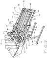
Figure 1 is a view in left side projection perspective of a standard digital printer with a side mounted manual feed tray that has been opened to access the manual feed tray feeder area and a feeder assembly of the present invention installed on the manual feed tray to feed envelopes into the digital printer. -
Figure 2 is a view in right side perspective of the feeder assembly ofFigure 1 . -
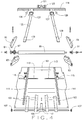
Figure 3 is an exploded view in exit end projection perspective of frame components and belt guide components of a delivery tray portion of the feeder assembly ofFigures 1 and2 . -
Figure 4 is an exploded view in exit end projection perspective of drive, bridge, and guide components of the delivery tray portion of the feeder assembly ofFigures 1 and2 . -
Figure 5 is a view in left side perspective of the delivery table portion of the feeder assembly ofFigures 1-4 , installed on a bypass tray of a digital printer. -
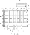
Figure 6 is a diagrammatic top plan view showing the interrelationship of the drives for a sheet feeder portion and the delivery table portion of the feeder assembly ofFigures 1-5 . -
Figure 7 is a view in left side perspective of a manual feed tray of a digital printer with a small stack of envelopes placed on the manual feed tray and the tray's stack support in a raised position, in accordance with the prior art. - Referring to the drawings,
reference numeral 1 indicates a sheet feeder assembly including asheet feeder 3 having pivotably attached thereto a delivery table 5. Thesheet feeder assembly 1, in this mode of carrying out the invention, interacts with a digital copying machine/printer 7 as described below. - The
sheet feeder assembly 1 is mounted on astand 9 havingwheels 11 andadjustable feet 13. Thestand 9 hastelescoping legs 15 withlocks 17 for setting the height of thesheet feeder assembly 1. If the floor on which thestand 9 rests is always expected to be level with the section of floor on which thedigital printer 7 rests, thelocks 17 may be pins which lock into holes in thelegs 15. Otherwise, thelocks 17 may be frictional locks of well-known design, to allow slight variance in the heights of thelegs 15. -
Sheet feeders 3 useable with the present invention are well known in the art. Although the structure of thesheet feeder 3 is not critical to the invention, it is preferably of top-load, bottom-feed design, allowing several hundred sheets to be loaded, and allowing more sheets to be loaded while the feeder is running. Thesheet feeder 3 is preferably made in accordance with Kaiping,United States Patent No. 7,624,978 . In brief, thesheet feeder 3 includes ahopper 31 designed to hold up to five hundredsheets 32 in the form of envelopes or cards, adrive shaft 33, and feedbelts 35 trained on thedrive shaft 33 and on anidler shaft 37 at the downstream end of thefeeder 3. As shown inFigure 6 , thedrive shaft 33 is driven at one end by an adjustable speedelectric motor 39 through abelt 43 trained over adrive gear 45 on theshaft 33. A secondtoothed pulley 47 is secured to the other end ofdrive shaft 33 for purposes described hereinafter. The positions of at least theouter feed belts 35 on theshafts feeder 3 is running.Separators 41 extend below the upper faces of thefeed belts 35 to buckle thelowermost sheet 32 and separate it from the stack. Thefeeder 3 is capable of delivering up to two hundred fifty #10 envelopes, having a height of about 4.125" (10.5 cm), per minute. - The delivery table 5 portion of the
feeder assembly 1, as best seen inFigures 3 and4 , includes two mountingplates 51 bolted to the sides of thefeeder 1.Side plates 53 are freely pivotably mounted to the mountingplates 51 by flat head screws 55,washers 56, and nylon insert lock nuts 57. Abelt guide bar 59, mounted betweenside plates 53, carries manually moveable belt guides 61 and fixed belt guides 63, which straddle lower reaches of delivery belts, as discussed below.Tensioner shaft 65 is mounted betweenside plates 53 forward (downstream) of thebelt guide bar 59 and carries twelve one-inch (2.54 cm) long ½" (1.23 cm)outer diameter bushings 67. Exit shaft bearing blocks 69 are mounted between theside plates 53 at the forward (exit) end of the delivery table 5. Anarcuate slot 71 in one of the mountingplates 51 accepts a lockinglever 73 threaded into one of theside plates 53. The lockinglever 73 allows the rotational position of theside plates 53 to be fixed during transport and positioning of the feeder assembly, but is loosened thereafter, to allow free pivoting of the delivery table 5 during alignment and use of thefeeder assembly 1. - A
table lift mechanism 75 is provided as a balance mechanism to reduce the effective weight of the delivery table. Thelift mechanism 75 includes anarm 77 bolted to one of the mountingplates 51. The free end of thearm 77 includes abore 79 sized to allow free passage of a threadedspring rod 81. Acoil spring 83 is held at its upper end by thespring rod 81 and at its lower end by abolt 85 threaded into aside plate 53. Anadjustment knob 87, threaded on the spring rod, permits adjustment of the spring tension, hence of the effective weight of the delivery table. If desired, the table can be adjusted to be effectively weightless, although it is preferred that the table exert some downward pressure, simulating a stack of sheets, as discussed hereinafter. - The delivery table 5 further includes a
drive shaft 89, best shown inFigures 4 and6 , rotatably mounted byflanged roller bearings 91 in bearing blocks 93 and held by bearingcaps 95. The bearing caps 95 are easily removed for servicing the drive roller or replacing drive belts. A geareddrive pulley 97 is mounted to one end of thedrive shaft 89 inside the bearingblock 93. Atoothed timing belt 99 runs between thedrive pulley 97 and the second gearedpulley 47 mounted on the end of thefeeder drive shaft 33 opposite the end driven byelectric motor 39. - A
top plate 101 is mounted between theside plates 53 and secured by flat-head bolts to drive shaft bearing blocks 93 and exit shaft bearing blocks 69. Thetop plate 101 supports the upper run ofdelivery belts 103 andsheets 32 as they are advanced from the feeder section to the printer by the deliverytable feed belts 103. - The delivery table 5 also includes an
exit shaft 105 around whichdelivery table belts 103 are trained. Theexit shaft 105 is rotationally driven by thedelivery table belts 103. Theexit shaft 105 is held in position by the two exit shaft bearing blocks 69 equipped withbearings 107 which allow free rotational movement of theexit shaft 105. - The
exit shaft 105 is sized to permit the exit end of the delivery table, including thebelts 103, to be less than 1.5" (5.1 cm) high, preferably one-half inch to one inch (1.2 - 2.5 cm) high, to permit the delivery table to fit into the printer's roller area without disturbing its manual feed tray. In the illustrative embodiment, theshaft 105 is 0.375" (0.95 cm) in diameter, turned down to 0.25" (0.635 cm) at its ends to fitbearings 107, and the height of theside plates 53 and bearing blocks 69 is 0.5625" (1.43 cm) at the exit end of the delivery table. The height of theexit shaft 105 plus thebelts 103 is about 0.5" (1.27 cm). - The width of the delivery table 5 is selected to fit a range of digital printers and to allow use with a range of sheet sizes. It will be understood that this requires a compromise. A general-purpose feeder assembly should have a width of at least 8.5" (21.5 cm) to handle U.S. letter-sized paper and should not be wider than about 14" (35.6 cm) to fit most digital printer manual feed trays. The illustrative embodiment has a width of 12.5" (31.8 cm) and can handle
sheets 3" (7.6 cm) wide minimum up to 12" (30.5 cm) wide, and from 4" (10 cm) long minimum to 18" (46 cm) long. The envelopes or sheets can be run in portrait or landscape orientation. - A one-
way bearing 109 is mounted in the center of theexit shaft 105 and is driven by theexit shaft 105 in the proper direction so as to advancesheets 32 into the printer's feed roller area. The one-way bearing 109 is positioned in use directly below the manual feed tray's feed roller. The one-way bearing 109 rotates freely in the direction of the printer when the printer's feed roller is activated to advance asheet 32 into the printer; it therefore does not impede advancement of thesheet 32 into the printer. - The delivery table
drive shaft pulley 97 is preferably of smaller diameter than thepulley 47 on the feedersection drive shaft 33, thereby causing the delivery table drive shaft to rotate at a higher rate than the feedersection drive shaft 33. This results in thedelivery table belts 103 having a higher advancing rate than that of the feedersection feed belts 35 and results in a gap between sheets as they advance toward the printer on the delivery table 5, as shown inFigure 5 . - The delivery
table top plate 101 includes paper guides 111 which are movable laterally toward and away from each other to accommodatesheets 32 of varying widths. These paper guides 111 serve to align thesheets 32 as they are advanced toward theprinter 7 so that eachsheet 32 is presented to the printer straight and in uniform position allowing for accurate print registration.Transverse slots 113 in theplate 101carry adjustment blocks 115 attached to the paper guides, for fixing their position. - The outermost
delivery table belts 103 are movable laterally toward and away from the center of the deliverytable top plate 101 so as to accommodate sheets of varying widths. This is accomplished by means of the two manually movable belt guides 61 shown inFigure 3 , and located below thetop plate 101. - The delivery
table top plate 101 includes aphoto sensor 117 secured to the bottom of the deliverytable top plate 101 near the exit end of the delivery table 5 in a position between two adjacentdelivery table belts 103 and directly underneath an opening cut into the deliverytable top plate 101. The upwardfacing photo sensor 117 detects the presence or absence ofsheets 32 at the exit end of the delivery table. Thephoto sensor 117 is electronically attached to the motor control mechanism to signal the motor to start running, advancing thesheets 32 toward the printer when thephoto sensor 117 detects the absence of asheet 32 at the exit end of the delivery table 5. When asheet 32 has advanced sufficiently to cover thephoto sensor 117, thephoto sensor 117 signals the motor controller to stop the motor. Thesheet 32 therefore stops in the proper position for the printer's feed roller to advance it into the printer. - The delivery table 5 includes a
bridge 119, best shown inFigures 2 ,4 and5 , which is attached to theside plates 53 on the ends of the bridge, and positioned above thetop plate 101, thedelivery belts 103, and the paper guides 111. Aninput roller assembly 121 is attached to thebridge 119 and includesrollers 123 that are positioned above and resting upon two adjacentcentral delivery belts 103. Theinput roller assembly 121 pushes the lead edge of thesheets 32 down onto thedelivery belts 103 as thesheets 32 exit the feeder section and enter the delivery table 5. This ensures consistent advancement of thesheets 32 during operation. Also attached to thebridge 119 are two laterally movable sheet hold downstraps 125 which rest on top of thesheets 32 as they are advanced toward the printer on the delivery table 5. The hold downstraps 125 serve to add sufficient downward force on thesheets 32 to insure adequate friction between thesheets 32 and thedelivery belts 103 so as to result in consistent advancement toward the printer of eachsubsequent sheet 32. The hold downstraps 125 are attached to thebridge 119 by twomovable slides 127. Themovable slides 127, and the attached hold downstraps 125, can be repositioned laterally to the most desirable location for varyingsheets 32. Themovable slides 127 include a lockingknob 128 that can be tightened to lock theslides 127 into position. In this embodiment,weights 129 are provided at the free, exit, ends of the hold downstraps 125. - Referring now to
Figure 7 , thesheet feeder assembly 1 of the illustrative embodiment is designed for use with high speed digital printer models with a flat paper path giving them the capability to handle envelopes and other thick or difficult sheets. These printers, such as theprinter 7 ofFigures 1 and7 , feature amanual feed tray 203 on the side of the printer. Themanual feed tray 203 is used for sheets that do not feed well in the standard internal paper trays. Envelopes are the most common such sheets.Figure 7 shows the normal orientation of themanual feed tray 203. Under normal usage, a pivoted feed table 204 portion of themanual feed tray 203 drops away a bit from afeed roller 205, allowing the operator to place a small stack ofenvelopes 32 onto the feed table part of thetray 203. When theprinter 7 is activated, the feed table 204 is mechanically raised, bringing the envelopes up until they contact thefeed roller 205 or a sensor adjacent thefeed roller 205. Thefeed roller 205 pulls thetop envelope 32 off the stack and pushes it into theprinter 7. This is repeated until the envelope stack is exhausted, when the feed table 204 will drop, allowing the operator to place another small stack of envelopes into thetray 203. This process is tedious, and themanual feed tray 203 typically only holds twenty to thirty envelopes, therefore requiring constant reloading. - When using the
sheet feeder assembly 1 of the present invention, themanual feed tray 203 is first emptied of any envelopes, causing the feed table 204 to drop to its lowest position. Paper guides on the tray are moved laterally outward to make maximum room for the delivery table 5 of thesheet feeder assembly 1. The exit end of the sheet feeder assembly's delivery table is then positioned into themanual feed tray 203, with the exit shaft just under the manual feed roller. Height adjustments may be made by loosening thelocks 17 on thelegs 15 of thestand 9 and then tightening the leg locks 17 when the proper height is reached. The locking lever on the left (operator) side of the delivery table is loosened so the delivery table can pivot freely. The delivery table 5 is lifted over the openedmanual feed tray 203 and slid into position so the delivery table goes in above themanual feed tray 203 and between themanual feed tray 203 paper guides. The end of the delivery table 5 is allowed to drop gently onto the feed table 204 of themanual feed tray 203, and thefeeder assembly 1 is pushed forward until the exit end of the delivery table 5 bumps into the front wall of themanual feed tray 203 and the one-way bearing 109 on the delivery table exit shaft is positioned just below, but not contacting, themanual feed tray 203feed roller 205. - In normal operation, the feed table 204 will push the delivery table 5 up until the one-way bearing contacts the
manual feed tray 203feed roller 205. The one-way bearing will press thefirst envelope 32 against themanual feed tray 203feed roller 205, but will spin freely as the feed roller pulls the envelope away. - Because the feed table 204 will be required to lift the sheet feeder assembly delivery table up to the feed roller, it is desirable to minimize the force it is required to exert, using the
balance mechanism 75. Once thefeeder assembly 1 is in position with theprinter 7, and the printer has not been started, theadjustment knob 87 is turned clockwise until the delivery table just starts to lift toward the feed roller. The one-way bearing 109 should not be lifted up to the feed roller; this is to be done by the feed table 204. The lift assist should only be strong enough to aid the feed table 204. - When the printer is activated, the feed table 204 lifts normally, which simply lifts the sheet feeder assembly's floating delivery table 5 up to the
feed roller 205, simulating a stack of envelopes. When the delivery table is pushed up it raises thefeed roller 205 or its sensor to the proper height, and the feed table 204 stops rising. The sheet feeder assembly then feeds asingle envelope 32 to thefeed roller 205, and on an internal signal from theprinter 7 thefeed roller 205 pulls the envelope into the printer. Thephoto sensor 117 mounted at the end of the delivery table detects when thefirst envelope 32 has left the delivery table 5, and signals thefeeder assembly 1 to advance anotherenvelope 32 to themanual feed roller 205. This process is repeated for each envelope required, with the feeder assembly being activated only when thephoto sensor 117 detects the absence of a sheet at the forward (exit) end of the delivery table 5. - Numerous variations in the construction of the feeder assembly of this invention, within the scope of the appended claims, will occur to those skilled in the art in light of the foregoing disclosure. Merely by way of example, other feeders may be used with the pivoting table. Although not preferred, the entire feeder assembly, including the table, could be pivotably mounted on a vertically adjustable stand. The balance mechanism which reduces the effective weight of the delivery table may include other types of springs, counterweights, or other known mechanisms. The top-feeding device into which the feeder assembly feeds may include different feed mechanisms. For example, the entire manual feed tray may lift when the printer calls for a sheet from the manual feed tray. The top-feeding device may be a simple vertically floating top-feed roller with a sheet sensor, adapted to handle a small stack of only a few sheets on a fixed sheet support. Rather than utilizing two different size pulleys to create different belt speeds between the feeder section and the delivery table section, the speed difference can be created by utilizing two different size shafts as well as utilization of a separate, independently controlled motor for the delivery table. Other devices, such as offset printing presses, utilize vacuum pickups, rather than feed rollers, as feeds, to move the top sheet of a stack into the device; the feeder assembly of the invention may be used with such devices, although the one-way roller is less important.
- These variations are merely illustrative.
Claims (13)
- In combination,
a printer (7) having a top-feed roller (205) accessible from outside the printer (7) and a feed table (204) positioned to hold a stack of sheets to be fed into the top-feed roller (205), and
a feeder assembly (1) comprising a bottom-feed sheet feeder (3) physically and electrically separate from the printer (7),
characterized in that the feeder assembly (1) further comprises a delivery table (5) positioned to receive sheets from the sheet feeder (3) and deliver the sheets one at a time to the top-feed roller (205), the delivery table (5) being pivotably mounted relative to the printer (7), to allow a free end of the delivery table (5) to move vertically with respect to the top-feed roller (205), the delivery table (5) being positioned on the feed table (204). - The combination of claim 1 wherein the delivery table (5) includes feed belts (103) which move the sheets from the feeder (3) to the top-feed roller (205) of the printer (7).
- The combination of claim 1 wherein the feed table (204) moves upwardly to feed sheets to the top feed roller (205), the delivery table (5) being positioned to be moved by the feed table (204).
- The combination of any of claims 1-3 wherein the delivery table (5) is pivotably mounted to the bottom-feed sheet feeder (3).
- The combination of claim 2 wherein feed belts (103) of the delivery table (5) are driven by the sheet feeder (3).
- The combination of claim 5 wherein the sheet feeder includes a sheet feeder drive roller (33) driven by an electric motor (39), and wherein the feed belts (103) of the delivery table (5) are trained on a drive table drive roller (89) driven by the sheet feeder drive roller (33).
- The combination of claim 5 or 6 wherein the belts (103) of the delivery table (5) are driven at a higher speed than the speed at which sheets are delivered by the sheet feeder (3).
- In combination,
a device (7) having a top-feed mechanism (203) accessible from outside the device (7), the top-feed mechanism (203) including a vertically moveable support (204) adapted to hold a stack of sheets and structure (205) that repeatedly delivers the top sheet from the stack into the device (7), and
a feeder assembly (1) comprising a bottom-feed sheet feeder (3) physically and electrically separate from the device (7),
characterized in that the feeder assembly (1) further comprises a delivery table (5) positioned to receive sheets from the sheet feeder (3) and deliver the sheets one at a time to the top-feed mechanism (203), an exit end of the delivery table (5) being supported by the vertically moveable support (204). - A method of feeding sheets to a manual feed tray (203) of a digital printer (7), the method characterized by lowering a sheet delivery table (5) onto a feed table (204) of the manual feed tray (203), and thereafter feeding sheets one at a time to the sheet delivery table (5) from a bottom-feeding, top-loading sheet feeder (3).
- A method of feeding sheets to a device (7) that includes a pulling mechanism (205) which pulls a top sheet from a stack of sheets, a support (204) for the stack of sheets and a sensor which detects the presence of at least one sheet, the method characterized by placing a sheet delivery table (5) on the support (204) to simulate a stack of sheets, and thereafter feeding sheets one at a time to the sheet delivery table (5) from a bottom-feeding, top-loading sheet feeder (3).
- The method of claim 10 comprising feeding a sheet in response to sensing the absence of a sheet at a position on the sheet delivery table (5) to be pulled by the device.
- The method of claim 10 or 11 wherein the support (204) lifts in response to the presence of a stack of sheets, and wherein the delivery table (5) is provided with a balance mechanism (75) which reduces the effective weight of the table to a weight which can be lifted by the support (204).
- The method of any of claims 10-12 wherein placing the delivery table (5) on the support (204) permits feeding of sheets from the delivery table (5) without modifying the support (204) or the sensor.
Applications Claiming Priority (3)
| Application Number | Priority Date | Filing Date | Title |
|---|---|---|---|
| US24120909P | 2009-09-10 | 2009-09-10 | |
| US37274510P | 2010-08-11 | 2010-08-11 | |
| PCT/US2010/048425 WO2011031966A2 (en) | 2009-09-10 | 2010-09-10 | Document feeder with pivoting delivery table, particularly for digital printers |
Publications (3)
| Publication Number | Publication Date |
|---|---|
| EP2475603A2 EP2475603A2 (en) | 2012-07-18 |
| EP2475603A4 EP2475603A4 (en) | 2015-05-27 |
| EP2475603B1 true EP2475603B1 (en) | 2016-04-20 |
Family
ID=43733104
Family Applications (1)
| Application Number | Title | Priority Date | Filing Date |
|---|---|---|---|
| EP10816154.8A Not-in-force EP2475603B1 (en) | 2009-09-10 | 2010-09-10 | Document feeder with pivoting delivery table, particularly for digital printers |
Country Status (5)
| Country | Link |
|---|---|
| US (1) | US8490964B2 (en) |
| EP (1) | EP2475603B1 (en) |
| AU (1) | AU2010292103B2 (en) |
| CA (1) | CA2772414C (en) |
| WO (1) | WO2011031966A2 (en) |
Families Citing this family (13)
| Publication number | Priority date | Publication date | Assignee | Title |
|---|---|---|---|---|
| US8702091B2 (en) * | 2011-05-24 | 2014-04-22 | James P. Schmidt | Printing stock feeder |
| JP5875404B2 (en) * | 2012-02-21 | 2016-03-02 | キヤノン株式会社 | Printing apparatus, control method therefor, and program |
| JP5875406B2 (en) | 2012-02-22 | 2016-03-02 | キヤノン株式会社 | Printing apparatus, control method therefor, and program |
| JP5892005B2 (en) * | 2012-08-31 | 2016-03-23 | キヤノンマーケティングジャパン株式会社 | Paper feeder |
| US9221629B1 (en) | 2012-09-28 | 2015-12-29 | Superior Paper Handling Solutions, Inc. | Friction feeder |
| JP6348602B2 (en) * | 2014-01-15 | 2018-06-27 | サンテ・コーポレイション | Envelope feeder with double conveyor aligned |
| DE102014211295B3 (en) * | 2014-06-13 | 2015-07-09 | Roth + Weber Gmbh | Folding machine for processing large format documents |
| JP6722067B2 (en) * | 2016-08-31 | 2020-07-15 | 株式会社沖データ | Medium transport device, medium supply device, and image forming system |
| WO2018106881A1 (en) * | 2016-12-07 | 2018-06-14 | Thiele Technologies, Inc. | Sheet feeder with transversely translatable floating final height adjustment block |
| US10322894B2 (en) * | 2017-05-01 | 2019-06-18 | Multifeeder Technologies, Inc. | Cleanable sheet feeder |
| US10640312B2 (en) | 2017-12-21 | 2020-05-05 | Superior Product Handling Solutions, Inc. | Friction feeding separating system |
| JP2022129289A (en) * | 2021-02-24 | 2022-09-05 | 富士フイルムビジネスイノベーション株式会社 | image forming device |
| JP2022155319A (en) | 2021-03-30 | 2022-10-13 | 株式会社リコー | Image formation apparatus |
Family Cites Families (9)
| Publication number | Priority date | Publication date | Assignee | Title |
|---|---|---|---|---|
| US4192496A (en) * | 1978-03-09 | 1980-03-11 | General Corrugated Machinery Co., Inc. | Apparatus for feeding case blank sheets |
| JPH0926730A (en) * | 1995-07-11 | 1997-01-28 | Ricoh Co Ltd | Device and system for forming image |
| JPH1045268A (en) | 1996-08-07 | 1998-02-17 | Tohoku Ricoh Co Ltd | Device for feeding paper in quantities |
| CA2382951A1 (en) * | 2002-04-22 | 2003-10-22 | Edward J. Cook | Feeding flexible products |
| US6932338B1 (en) * | 2002-11-01 | 2005-08-23 | Streamfeeder, Llc | Friction sheet feeding machine with reversible driven retard roller |
| JP2005059982A (en) * | 2003-08-20 | 2005-03-10 | Sharp Corp | Sheet conveying device and image forming system having the same |
| GB2417949B (en) | 2004-09-09 | 2008-04-02 | Pitney Bowes Ltd | Sheet material feeder |
| JP2006082912A (en) * | 2004-09-15 | 2006-03-30 | Clover Engineering Kk | Sheet feeder, sheet feeding method and image formation system using this |
| US7624978B2 (en) | 2005-03-16 | 2009-12-01 | Kaiping James C | Sheet feeder with feed belts that move toward an away from each other |
-
2010
- 2010-09-10 WO PCT/US2010/048425 patent/WO2011031966A2/en active Application Filing
- 2010-09-10 US US13/148,014 patent/US8490964B2/en active Active
- 2010-09-10 CA CA2772414A patent/CA2772414C/en not_active Expired - Fee Related
- 2010-09-10 EP EP10816154.8A patent/EP2475603B1/en not_active Not-in-force
- 2010-09-10 AU AU2010292103A patent/AU2010292103B2/en not_active Ceased
Also Published As
| Publication number | Publication date |
|---|---|
| EP2475603A2 (en) | 2012-07-18 |
| AU2010292103B2 (en) | 2013-06-13 |
| EP2475603A4 (en) | 2015-05-27 |
| WO2011031966A3 (en) | 2011-06-16 |
| WO2011031966A2 (en) | 2011-03-17 |
| CA2772414C (en) | 2015-10-20 |
| US8490964B2 (en) | 2013-07-23 |
| US20110291348A1 (en) | 2011-12-01 |
| CA2772414A1 (en) | 2011-03-17 |
| AU2010292103A1 (en) | 2012-03-08 |
Similar Documents
| Publication | Publication Date | Title |
|---|---|---|
| EP2475603B1 (en) | Document feeder with pivoting delivery table, particularly for digital printers | |
| US5829898A (en) | Printing assembly with discrete load enhancement apparatus and method | |
| GB2038289A (en) | Sheet separating apparatus | |
| US8353510B2 (en) | Variable media feed system and printhead apparatus | |
| US7021621B2 (en) | Sheet-supply device and printing device including the same | |
| JPS62211265A (en) | Discharged sheet receiving device | |
| JPH07199556A (en) | Automatic document feeder | |
| US5823527A (en) | Control for a sheet stack supporting platform | |
| EP0036072A1 (en) | Sheet paper feed apparatus | |
| JP4122282B2 (en) | Paper feeder | |
| JP6348602B2 (en) | Envelope feeder with double conveyor aligned | |
| US20090189334A1 (en) | Vacuum friction feeder | |
| JPH08301500A (en) | Paper feeder/discharger for stencil printer | |
| JPH07197929A (en) | Hinge device | |
| JPH04341458A (en) | Sheet post-processing device | |
| JPH054731A (en) | Sheet feeder | |
| JP3315217B2 (en) | Paper feeder | |
| JPH04197926A (en) | Back fence device for mass paper feeding conveyor device | |
| KR100492340B1 (en) | A card supply apparatus for card-printer | |
| JP4105250B2 (en) | Paper output sorting device | |
| JP2519877B2 (en) | Paper feeder | |
| JP2576875Y2 (en) | Paper feeder | |
| JPH06286265A (en) | Printing apparatus | |
| JPH10181919A (en) | Hand insertion paper feeder for image forming device | |
| JPH11263449A (en) | Paper feeder |
Legal Events
| Date | Code | Title | Description |
|---|---|---|---|
| PUAI | Public reference made under article 153(3) epc to a published international application that has entered the european phase |
Free format text: ORIGINAL CODE: 0009012 |
|
| 17P | Request for examination filed |
Effective date: 20120320 |
|
| AK | Designated contracting states |
Kind code of ref document: A2 Designated state(s): AL AT BE BG CH CY CZ DE DK EE ES FI FR GB GR HR HU IE IS IT LI LT LU LV MC MK MT NL NO PL PT RO SE SI SK SM TR |
|
| DAX | Request for extension of the european patent (deleted) | ||
| RIC1 | Information provided on ipc code assigned before grant |
Ipc: B65H 11/00 20060101ALI20141222BHEP Ipc: B65H 7/02 20060101ALI20141222BHEP Ipc: G03G 15/00 20060101ALI20141222BHEP Ipc: B65H 3/04 20060101AFI20141222BHEP |
|
| REG | Reference to a national code |
Ref country code: DE Ref legal event code: R079 Ref document number: 602010032647 Country of ref document: DE Free format text: PREVIOUS MAIN CLASS: B65H0001260000 Ipc: B65H0003040000 |
|
| A4 | Supplementary search report drawn up and despatched |
Effective date: 20150430 |
|
| RIC1 | Information provided on ipc code assigned before grant |
Ipc: B65H 11/00 20060101ALI20150423BHEP Ipc: B65H 3/04 20060101AFI20150423BHEP Ipc: G03G 15/00 20060101ALI20150423BHEP Ipc: B65H 7/02 20060101ALI20150423BHEP |
|
| GRAP | Despatch of communication of intention to grant a patent |
Free format text: ORIGINAL CODE: EPIDOSNIGR1 |
|
| INTG | Intention to grant announced |
Effective date: 20151106 |
|
| GRAS | Grant fee paid |
Free format text: ORIGINAL CODE: EPIDOSNIGR3 |
|
| GRAA | (expected) grant |
Free format text: ORIGINAL CODE: 0009210 |
|
| AK | Designated contracting states |
Kind code of ref document: B1 Designated state(s): AL AT BE BG CH CY CZ DE DK EE ES FI FR GB GR HR HU IE IS IT LI LT LU LV MC MK MT NL NO PL PT RO SE SI SK SM TR |
|
| REG | Reference to a national code |
Ref country code: GB Ref legal event code: FG4D |
|
| REG | Reference to a national code |
Ref country code: CH Ref legal event code: EP |
|
| REG | Reference to a national code |
Ref country code: AT Ref legal event code: REF Ref document number: 792200 Country of ref document: AT Kind code of ref document: T Effective date: 20160515 |
|
| REG | Reference to a national code |
Ref country code: IE Ref legal event code: FG4D |
|
| REG | Reference to a national code |
Ref country code: DE Ref legal event code: R096 Ref document number: 602010032647 Country of ref document: DE |
|
| REG | Reference to a national code |
Ref country code: LT Ref legal event code: MG4D |
|
| REG | Reference to a national code |
Ref country code: AT Ref legal event code: MK05 Ref document number: 792200 Country of ref document: AT Kind code of ref document: T Effective date: 20160420 |
|
| REG | Reference to a national code |
Ref country code: FR Ref legal event code: PLFP Year of fee payment: 7 |
|
| REG | Reference to a national code |
Ref country code: NL Ref legal event code: MP Effective date: 20160420 |
|
| PG25 | Lapsed in a contracting state [announced via postgrant information from national office to epo] |
Ref country code: NO Free format text: LAPSE BECAUSE OF FAILURE TO SUBMIT A TRANSLATION OF THE DESCRIPTION OR TO PAY THE FEE WITHIN THE PRESCRIBED TIME-LIMIT Effective date: 20160720 Ref country code: FI Free format text: LAPSE BECAUSE OF FAILURE TO SUBMIT A TRANSLATION OF THE DESCRIPTION OR TO PAY THE FEE WITHIN THE PRESCRIBED TIME-LIMIT Effective date: 20160420 Ref country code: LT Free format text: LAPSE BECAUSE OF FAILURE TO SUBMIT A TRANSLATION OF THE DESCRIPTION OR TO PAY THE FEE WITHIN THE PRESCRIBED TIME-LIMIT Effective date: 20160420 Ref country code: NL Free format text: LAPSE BECAUSE OF FAILURE TO SUBMIT A TRANSLATION OF THE DESCRIPTION OR TO PAY THE FEE WITHIN THE PRESCRIBED TIME-LIMIT Effective date: 20160420 Ref country code: PL Free format text: LAPSE BECAUSE OF FAILURE TO SUBMIT A TRANSLATION OF THE DESCRIPTION OR TO PAY THE FEE WITHIN THE PRESCRIBED TIME-LIMIT Effective date: 20160420 |
|
| PG25 | Lapsed in a contracting state [announced via postgrant information from national office to epo] |
Ref country code: HR Free format text: LAPSE BECAUSE OF FAILURE TO SUBMIT A TRANSLATION OF THE DESCRIPTION OR TO PAY THE FEE WITHIN THE PRESCRIBED TIME-LIMIT Effective date: 20160420 Ref country code: ES Free format text: LAPSE BECAUSE OF FAILURE TO SUBMIT A TRANSLATION OF THE DESCRIPTION OR TO PAY THE FEE WITHIN THE PRESCRIBED TIME-LIMIT Effective date: 20160420 Ref country code: AT Free format text: LAPSE BECAUSE OF FAILURE TO SUBMIT A TRANSLATION OF THE DESCRIPTION OR TO PAY THE FEE WITHIN THE PRESCRIBED TIME-LIMIT Effective date: 20160420 Ref country code: SE Free format text: LAPSE BECAUSE OF FAILURE TO SUBMIT A TRANSLATION OF THE DESCRIPTION OR TO PAY THE FEE WITHIN THE PRESCRIBED TIME-LIMIT Effective date: 20160420 Ref country code: LV Free format text: LAPSE BECAUSE OF FAILURE TO SUBMIT A TRANSLATION OF THE DESCRIPTION OR TO PAY THE FEE WITHIN THE PRESCRIBED TIME-LIMIT Effective date: 20160420 Ref country code: PT Free format text: LAPSE BECAUSE OF FAILURE TO SUBMIT A TRANSLATION OF THE DESCRIPTION OR TO PAY THE FEE WITHIN THE PRESCRIBED TIME-LIMIT Effective date: 20160822 Ref country code: GR Free format text: LAPSE BECAUSE OF FAILURE TO SUBMIT A TRANSLATION OF THE DESCRIPTION OR TO PAY THE FEE WITHIN THE PRESCRIBED TIME-LIMIT Effective date: 20160721 |
|
| PG25 | Lapsed in a contracting state [announced via postgrant information from national office to epo] |
Ref country code: BE Free format text: LAPSE BECAUSE OF FAILURE TO SUBMIT A TRANSLATION OF THE DESCRIPTION OR TO PAY THE FEE WITHIN THE PRESCRIBED TIME-LIMIT Effective date: 20160420 Ref country code: IT Free format text: LAPSE BECAUSE OF FAILURE TO SUBMIT A TRANSLATION OF THE DESCRIPTION OR TO PAY THE FEE WITHIN THE PRESCRIBED TIME-LIMIT Effective date: 20160420 |
|
| REG | Reference to a national code |
Ref country code: DE Ref legal event code: R097 Ref document number: 602010032647 Country of ref document: DE |
|
| PG25 | Lapsed in a contracting state [announced via postgrant information from national office to epo] |
Ref country code: EE Free format text: LAPSE BECAUSE OF FAILURE TO SUBMIT A TRANSLATION OF THE DESCRIPTION OR TO PAY THE FEE WITHIN THE PRESCRIBED TIME-LIMIT Effective date: 20160420 Ref country code: RO Free format text: LAPSE BECAUSE OF FAILURE TO SUBMIT A TRANSLATION OF THE DESCRIPTION OR TO PAY THE FEE WITHIN THE PRESCRIBED TIME-LIMIT Effective date: 20160420 Ref country code: CZ Free format text: LAPSE BECAUSE OF FAILURE TO SUBMIT A TRANSLATION OF THE DESCRIPTION OR TO PAY THE FEE WITHIN THE PRESCRIBED TIME-LIMIT Effective date: 20160420 Ref country code: SK Free format text: LAPSE BECAUSE OF FAILURE TO SUBMIT A TRANSLATION OF THE DESCRIPTION OR TO PAY THE FEE WITHIN THE PRESCRIBED TIME-LIMIT Effective date: 20160420 Ref country code: DK Free format text: LAPSE BECAUSE OF FAILURE TO SUBMIT A TRANSLATION OF THE DESCRIPTION OR TO PAY THE FEE WITHIN THE PRESCRIBED TIME-LIMIT Effective date: 20160420 |
|
| PLBE | No opposition filed within time limit |
Free format text: ORIGINAL CODE: 0009261 |
|
| STAA | Information on the status of an ep patent application or granted ep patent |
Free format text: STATUS: NO OPPOSITION FILED WITHIN TIME LIMIT |
|
| PG25 | Lapsed in a contracting state [announced via postgrant information from national office to epo] |
Ref country code: SM Free format text: LAPSE BECAUSE OF FAILURE TO SUBMIT A TRANSLATION OF THE DESCRIPTION OR TO PAY THE FEE WITHIN THE PRESCRIBED TIME-LIMIT Effective date: 20160420 |
|
| 26N | No opposition filed |
Effective date: 20170123 |
|
| PG25 | Lapsed in a contracting state [announced via postgrant information from national office to epo] |
Ref country code: MC Free format text: LAPSE BECAUSE OF FAILURE TO SUBMIT A TRANSLATION OF THE DESCRIPTION OR TO PAY THE FEE WITHIN THE PRESCRIBED TIME-LIMIT Effective date: 20160420 |
|
| REG | Reference to a national code |
Ref country code: CH Ref legal event code: PL |
|
| PG25 | Lapsed in a contracting state [announced via postgrant information from national office to epo] |
Ref country code: SI Free format text: LAPSE BECAUSE OF FAILURE TO SUBMIT A TRANSLATION OF THE DESCRIPTION OR TO PAY THE FEE WITHIN THE PRESCRIBED TIME-LIMIT Effective date: 20160420 |
|
| REG | Reference to a national code |
Ref country code: IE Ref legal event code: MM4A |
|
| PG25 | Lapsed in a contracting state [announced via postgrant information from national office to epo] |
Ref country code: LI Free format text: LAPSE BECAUSE OF NON-PAYMENT OF DUE FEES Effective date: 20160930 Ref country code: CH Free format text: LAPSE BECAUSE OF NON-PAYMENT OF DUE FEES Effective date: 20160930 Ref country code: IE Free format text: LAPSE BECAUSE OF NON-PAYMENT OF DUE FEES Effective date: 20160910 |
|
| PG25 | Lapsed in a contracting state [announced via postgrant information from national office to epo] |
Ref country code: LU Free format text: LAPSE BECAUSE OF NON-PAYMENT OF DUE FEES Effective date: 20160910 |
|
| REG | Reference to a national code |
Ref country code: FR Ref legal event code: PLFP Year of fee payment: 8 |
|
| PG25 | Lapsed in a contracting state [announced via postgrant information from national office to epo] |
Ref country code: CY Free format text: LAPSE BECAUSE OF FAILURE TO SUBMIT A TRANSLATION OF THE DESCRIPTION OR TO PAY THE FEE WITHIN THE PRESCRIBED TIME-LIMIT Effective date: 20160420 Ref country code: HU Free format text: LAPSE BECAUSE OF FAILURE TO SUBMIT A TRANSLATION OF THE DESCRIPTION OR TO PAY THE FEE WITHIN THE PRESCRIBED TIME-LIMIT; INVALID AB INITIO Effective date: 20100910 |
|
| PG25 | Lapsed in a contracting state [announced via postgrant information from national office to epo] |
Ref country code: MK Free format text: LAPSE BECAUSE OF FAILURE TO SUBMIT A TRANSLATION OF THE DESCRIPTION OR TO PAY THE FEE WITHIN THE PRESCRIBED TIME-LIMIT Effective date: 20160420 Ref country code: IS Free format text: LAPSE BECAUSE OF FAILURE TO SUBMIT A TRANSLATION OF THE DESCRIPTION OR TO PAY THE FEE WITHIN THE PRESCRIBED TIME-LIMIT Effective date: 20160420 Ref country code: MT Free format text: LAPSE BECAUSE OF NON-PAYMENT OF DUE FEES Effective date: 20160930 Ref country code: TR Free format text: LAPSE BECAUSE OF FAILURE TO SUBMIT A TRANSLATION OF THE DESCRIPTION OR TO PAY THE FEE WITHIN THE PRESCRIBED TIME-LIMIT Effective date: 20160420 |
|
| PG25 | Lapsed in a contracting state [announced via postgrant information from national office to epo] |
Ref country code: BG Free format text: LAPSE BECAUSE OF FAILURE TO SUBMIT A TRANSLATION OF THE DESCRIPTION OR TO PAY THE FEE WITHIN THE PRESCRIBED TIME-LIMIT Effective date: 20160420 |
|
| REG | Reference to a national code |
Ref country code: FR Ref legal event code: PLFP Year of fee payment: 9 |
|
| PG25 | Lapsed in a contracting state [announced via postgrant information from national office to epo] |
Ref country code: AL Free format text: LAPSE BECAUSE OF FAILURE TO SUBMIT A TRANSLATION OF THE DESCRIPTION OR TO PAY THE FEE WITHIN THE PRESCRIBED TIME-LIMIT Effective date: 20160420 |
|
| PGFP | Annual fee paid to national office [announced via postgrant information from national office to epo] |
Ref country code: FR Payment date: 20190925 Year of fee payment: 10 |
|
| PGFP | Annual fee paid to national office [announced via postgrant information from national office to epo] |
Ref country code: GB Payment date: 20190927 Year of fee payment: 10 |
|
| PGFP | Annual fee paid to national office [announced via postgrant information from national office to epo] |
Ref country code: DE Payment date: 20190927 Year of fee payment: 10 |
|
| REG | Reference to a national code |
Ref country code: DE Ref legal event code: R119 Ref document number: 602010032647 Country of ref document: DE |
|
| GBPC | Gb: european patent ceased through non-payment of renewal fee |
Effective date: 20200910 |
|
| PG25 | Lapsed in a contracting state [announced via postgrant information from national office to epo] |
Ref country code: DE Free format text: LAPSE BECAUSE OF NON-PAYMENT OF DUE FEES Effective date: 20210401 Ref country code: FR Free format text: LAPSE BECAUSE OF NON-PAYMENT OF DUE FEES Effective date: 20200930 |
|
| PG25 | Lapsed in a contracting state [announced via postgrant information from national office to epo] |
Ref country code: GB Free format text: LAPSE BECAUSE OF NON-PAYMENT OF DUE FEES Effective date: 20200910 |