EP2475081A1 - Starting and running device for a compressor and method of assembling a starting and running device for a compressor - Google Patents
Starting and running device for a compressor and method of assembling a starting and running device for a compressor Download PDFInfo
- Publication number
- EP2475081A1 EP2475081A1 EP11150386A EP11150386A EP2475081A1 EP 2475081 A1 EP2475081 A1 EP 2475081A1 EP 11150386 A EP11150386 A EP 11150386A EP 11150386 A EP11150386 A EP 11150386A EP 2475081 A1 EP2475081 A1 EP 2475081A1
- Authority
- EP
- European Patent Office
- Prior art keywords
- casing
- capacitor
- starting
- closure
- running device
- Prior art date
- Legal status (The legal status is an assumption and is not a legal conclusion. Google has not performed a legal analysis and makes no representation as to the accuracy of the status listed.)
- Granted
Links
Images



Classifications
-
- H—ELECTRICITY
- H02—GENERATION; CONVERSION OR DISTRIBUTION OF ELECTRIC POWER
- H02K—DYNAMO-ELECTRIC MACHINES
- H02K17/00—Asynchronous induction motors; Asynchronous induction generators
- H02K17/02—Asynchronous induction motors
- H02K17/30—Structural association of asynchronous induction motors with auxiliary electric devices influencing the characteristics of the motor or controlling the motor, e.g. with impedances or switches
-
- H—ELECTRICITY
- H02—GENERATION; CONVERSION OR DISTRIBUTION OF ELECTRIC POWER
- H02K—DYNAMO-ELECTRIC MACHINES
- H02K11/00—Structural association of dynamo-electric machines with electric components or with devices for shielding, monitoring or protection
- H02K11/20—Structural association of dynamo-electric machines with electric components or with devices for shielding, monitoring or protection for measuring, monitoring, testing, protecting or switching
- H02K11/27—Devices for sensing current, or actuated thereby
Definitions
- the present disclosure relates to a starting and running device for a compressor.
- the device may be used with a resistance start - capacitor run (RSCR) type compressor motor.
- RSCR resistance start - capacitor run
- the compressor motor may be part of a refrigerator, in particular a house hold refrigerator, a freezer, an air conditioner or a heat pump.
- the starting and running device for a compressor comprises a casing enclosing a capacitor, a starter and an overload protector.
- the capacitor is fixed to the casing by a filling agent.
- the device may be designed as a starting and running device for a compressor motor.
- the capacitor may be designed as a motor run capacitor and may be connected to the compressor motor during a running phase.
- the capacitor is connected to an auxiliary coil of the compressor and, thereby, improves the performance of the compressor.
- the starter may comprise a PTC (positive temperature coefficient) element.
- the compressor motor may be started by making use of the PTC-effect, i.e., the increase of resistance with an increase of temperature.
- the compressor may comprise a single phase induction motor comprising a main coil and an auxiliary coil.
- the PTC element allows a high current flow in the auxiliary coil, which causes the motor to start. When the starting operation is over, the current is reduced or cut off in the auxiliary coil.
- the overload protector serves to protect the motor by cutting off the current flow to the compressor motor in case that the temperature of the compressor motor rises above a maximum value.
- the overload protector may comprise a bimetal.
- a starting and running device By positioning the capacitor, the starter and the overload protector in a common casing, a starting and running device is provided which may be easily handled and attached to a compressor motor.
- the device is provided as a single component wherein the capacitor, starter and overload protector are integrated.
- the components By providing the components in a finished unit, where the position of each component is fixed, testing and quality control of the parts in their final positions is enabled and the quality of the starting and running device can be improved.
- the installation of the components to the compressor may be facilitated as the electrical connection between the components may be provided within the device.
- the starting and running device is designed as a plug-in type device which can be connected to the compressor motor by plugging the device onto the compressor motor.
- a complex wiring of the components to the compressor can be avoided and the step of installing the device can be facilitated.
- the capacitor may be free from any additional capacitor casing, and, in particular, free from a casing between a capacitor coil of the capacitor and the casing of the device. In this case, a minimum of space is required for the capacitor in the casing.
- the casing may have a compartment for housing the capacitor.
- the compartment may be a cylindrical, in particular a circular cylindrical, compartment.
- the shape of the compartment may be adapted to the shape of the capacitor coil such that a minimum of space is wasted when housing the capacitor.
- the capacitor coil is directly fixed to the casing by the filling agent.
- the filling agent no additional elements or materials may be present between the capacitor coil and the filling agent.
- the entire space between a lateral side wall of the capacitor coil, which may be the lateral surface area of a cylindrical capacitor coil, and the casing is filled by the filling agent.
- the filling agent may cover the capacitor coil.
- the filling agent may cover a base area of the capacitor coil which points to an opening of the casing through which the filling agent is filled in the casing.
- the filling agent entirely covers the capacitor coil and, thereby, may hermetically enclose the capacitor coil.
- an area of the capacitor coil may be not covered by the filling agent.
- a part of the surface area which may be a top surface of the capacitor coil, may be in direct contact with the casing.
- the capacitor coil When assembling the device, the capacitor coil may be placed with its top surface ahead in the casing such that the capacitor coil comes to rest with its top surface on a base of the casing. Then, the filling agent may be filled in the casing such that it encloses the capacitor coil.
- the capacitor coil is hermetically enclosed by the filling agent in conjunction with the casing and, in particular, in conjunction with the base of the casing.
- the filling agent may comprise a resin material.
- the resin material may be filled in the casing such that it fills a gap between the casing and the capacitor coil and such that it covers a bottom side of the capacitor coil.
- the capacitor, the starter and the overload protector are positioned relative to each other such that a favorable temperature distribution is achieved.
- the starter element which may be a source of heat, may be positioned in a distance to the capacitor coil, such that the temperature at the capacitor coil does not rise above a rated temperature of the capacitor coil.
- the maximum temperature at the PTC element may be above 100 °C, while the rated temperature of the capacitor may be less than 85 °C.
- the starter element is positioned in a distance to the overload protector such that the temperature at the overload protector does not rise above a rated temperature of the overload protector.
- the starter element is thermally insulated by a thermal insulation material.
- the thermal insulation material may serve to insulate the PTC element from other components of the device or from the casing.
- an insulation material may be provided at the base of the casing in the area where the PTC element is positioned.
- the insulation material may comprise a mica material.
- the maximum temperature of the part of the casing nearest to the capacitor coil is kept below the rated temperature of the capacitor coil.
- the PTC element By thermally insulating the PTC element, also the power consumed by the PTC element may be reduced.
- the PTC element may be insulated by air or high temperature grade material, such as mica or an equivalent.
- the response time for the PTC element to switch on the compressor motor can be reduced, for example, it may be ensured that the response time is less than six seconds.
- the overload protector is positioned in the casing such that its temperature sensing part is optimally close to the compressor when the device is attached to the compressor. Thereby, a high coefficient of performance for the overload protector can be achieved such that the overload protector detects thermal overload with a minimum of reaction time.
- the electrical connection between the capacitor, the starter and the overload protector is provided inside the casing.
- the capacitor may be electrically connected to the starter by connecting wires.
- the casing comprises a closure configured for closing the casing.
- the device may be configured such that the closure is positioned on that side of the device which is attached to the compressor motor.
- the closure may be attached to a bottom side of the casing.
- the closure may comprise openings for receiving connection terminals of the compressor.
- the closure may have the shape of a lid. It may be formed from the same material as the casing.
- the casing may be formed as a unitary piece.
- the casing may be formed as a unity piece except from the closure.
- the closure is also formed as a unitary piece.
- the casing comprises an opening through which the capacitor, starter and overload protector can be positioned in the casing.
- the closure may be configured to at least partially cover the opening and thus, protect the elements inside the casing.
- the closure may cover the parts of the casing where the capacitor coil and the starter are positioned.
- the closure may be configured such that the overload protector remains uncovered by the closure when the closure is attached to the casing.
- it may be shaped such that at least the sensing part of the overload protector is not covered.
- the sensing part may be placed directly adjacent to the compressor without a casing in-between. Thereby, the thermal coupling of the compressor and the overload protector can be improved as no barrier is present between the compressor and the overload protector.
- the closure is configured to be closed and reopened such that a replacement of elements of the device is enabled.
- the closure may be configured such that a replacement of the starter is enabled.
- the closure may be attached to the casing by a lead screw.
- the starting and running device may be configured such that a replacement of the overload protector is enabled without opening a closure.
- a simple replacement of the overload protector is enabled.
- a replacement of the overload protector is also enabled in the case that the closure is not re-openable.
- a method for assembling a starting and running device for a compressor comprises the steps of
- steps A), B) and C) are carried out consecutively in the given order.
- an overload protector is placed in the casing, for example after step C).
- the capacitor, starter, overload protector and casing may comprise any of the features as described above.
- the capacitor comprises a capacitor coil, which is directly fixed to the casing by the filling agent.
- the filling agent may be a resin material.
- the casing may comprise a compartment which is separated by walls from the parts of the casing where the starter and the overload protector are positioned.
- the resin material may be filled into the compartment such that it encloses the capacitor coil.
- the capacitor Prior to step C), the capacitor may be electrically connected and, thereby, in particular, electrically connected to the starter.
- the starter may comprise terminals which may be connected to electrical connection elements, for example electric wires of the capacitor.
- the wires may be welded to the terminals of the starter. After connecting the capacitor to the starter, the terminals may be positioned in the casing.
- the capacitor which is placed in the casing in step B) is free from a capacitor casing.
- the method may further comprise the step of
- the starter and the capacitor are placed in the casing before the casing is closed by the closure.
- the overload protector may be positioned in the casing after the closing of the casing.
- the overload protector may be positioned in a compartment of the casing which is not covered by the closure. Thereby, a replacement of the overload protector may be enabled without that the closure has to be reopened.
- Figure 1 shows a first embodiment of a starting and running device 1 for use with a compressor motor.
- the starting and running device 1 comprises a casing 2 which houses a capacitor 3, a starter 4 and an overload protector 5.
- the starting and running device 1 is designed as a single component which can be easily attached to a compressor motor by plugging-in the device 1.
- the casing 2 is formed as a unitary piece except from an additional closure (not shown here), by which the casing 2 can be at least partially closed.
- the casing 2 is made from a plastic material and may be formed in an injection molding process.
- the casing 2 has an opening 9 which allows a placement of the capacitor 3, the starter 4 and the overload protector 5 in the casing 2.
- the casing 2 fully encloses the PTC starter 4, the capacitor 3 and the overload protector 5 except from the opening 9 on the bottom side 7 of the casing 2.
- the casing conforms to IP 55 or IP 56 protection according to the International Standard IEC 60259. In particular, the casing is protected against tools and wires over 1 mm diameter and against dust.
- the casing comprises a cylindrical compartment 10, wherein the capacitor 3 is positioned.
- the capacitor 3 may be designed as a motor run capacitor.
- the capacitor 3 comprises a capacitor coil which may be wound from two layers of a metalized, segmented or non-segmented film comprising polypropylene.
- the capacitor 3 is directly fixed to the casing 2 by a filling agent 21.
- the capacitor 3 is free from an additional capacitor casing.
- the capacitor 3 is either of class P0 or P2 according to the International Standard IEC 60252-1 2001.
- the filling agent 21 completely covers the bottom side of the capacitor coil, wherein the bottom side is the side of the capacitor coil pointing to the opening 9, and fills the space between the capacitor coil and the cylindrical compartment 10 of the casing 2.
- the filling agent 21 serves to fix the capacitor coil 3 to the casing 2 and provides a protection against mechanical and chemical damages.
- the resin material provides an electrical insulation of the capacitor coil.
- the filling agent 21 is made from a resin material.
- the material of the casing 2 and the material of the filling agent 21 is in compliance with the International Standard IEC 60335-1 Edition 5.0 2010-05.
- the device 1 comprises to RoHs requirements as per EU Directive 2002/95/EC.
- the starter 4 comprises a PTC element.
- the PTC element may have the shape of a disc and may comprise a ceramic material as BaTiO 3 , for example.
- the PTC pill may have a diameter of between 16 and 20 mm.
- the overload protector 5 comprises a bimetal, by which the current flow to the compressor motor is cut off in the case that the temperature rises above a maximum temperature.
- the overload protector 5 has a flat shape.
- the capacitor 3 may comprise connection wires for electrical connection with terminals of the PTC starter 4.
- the length of the connection wires is kept as small as possible in order to minimize the resistance of the wires and a subsequent loss of energy.
- the elements in the device 1 are positioned such that a favourable temperature distribution is achieved in the device 1.
- the PTC starter 4 which generates heat, is positioned in a suitable distance from both the capacitor 3 and the overload protector 5 to avoid a heating of the capacitor 3 and the overload protector 5 over their rated temperatures.
- the PTC starter 4 is placed on a thermal insulation material to thermally insulate the PTC starter 4 from the casing 2 and, thereby, avoid excessive heating of the casing 2.
- Figure 2 shows the starting and running device 1 of Figure 1 in a perspective side view.
- a first electrical connection element 11 for electrically connecting the overload protector 5 to a power supply and a second electrical connection element 12 for electrically connecting the starter 4 to a power supply are led through the casing 2 at the top side 8 of the casing 2.
- Figure 3 shows the starting and running device 1 of Figure 1 with a closure 5 attached to the bottom side 7 of the casing 2.
- the closure 5 is made from a plastic material and formed in an injection molding process.
- the closure 5 is fixed by a lead-screw to the casing 2.
- the lead screw is positioned in a small opening 13 in the closure 5.
- the electrical connections 14, 15, 16 are accessible through openings in the closure 5 and are configured to receive electrical terminals of the compressor.
- further fixation means may be provided for fixing the device 1 to the compressor.
- the compressor may comprise flanges or a metal wire clamp.
- the device may be fixed to the compressor by a solid wire clamp, a metal strap or a screw fixation.
- the closure 5 covers the compartment 10 of the casing 2 wherein the capacitor 3 is seated and the part of the casing 2 wherein the PTC starter 4 is seated.
- the closure 2 does not cover the overload protector 5. Thereby, the thermal coupling of the overload protector 5 and the compressor is improved. Furthermore, this enables the overload protector 5 to be replaced without re-opening the closure 2.
- Figure 4 shows the starting and running device 1 during its assembly on a holder 17, which can be attached to the compressor motor.
- the starting and running device 1 is plugged onto the holder 17 such that terminals 18 are received in electrical connections 14, 15, 16 at the bottom side 7 of the casing 2.
- the starter device 1 can be electrically connected to a power supply via its connection elements 11, 12 at the top side 8 of the starting and running device 1.
- the holder 17 comprises fixation means 22, 23, 24 for fixing the device 1 on the compressor motor.
- a clamp fixation of the device 1 is achieved.
- the fixation means 22, 23, 24 ensure a correct configuration of the device 1 on the compressor motor and may also ensure IP protection.
- Figure 5 shows a schematic top view of the starting and running device 1 assembled on the holder 17.
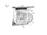
- Figure 6 shows a top view of the starting and running device 1 of figure 1 attached to a compressor 19.
- the starting and running device 1 is seated on a holder 7, which is fixed to the compressor 19, for example fixed by welding, seaming or clinching.
- Figure 7 shows a second embodiment of a starting and running device 1.
- the overload protector 5 is of a round type and, in particular, a circular cylindrical shape.
- the casing may be designed such that it may accommodate a round type or a flat type overload protector.
- the closure is snap-fitted to the casing.
- the casing is designed not to be reopened.
- the starting and running devices shown in Figures 1 to 7 may be assembled as follows. First, the capacitor 3 is placed in its compartment 10 in the casing 2. Thereafter, a filling material 21 is filled in the casing 2 to cover the capacitor coil 3 and is cured. After that, the connection wires of the capacitor 3 are connected to terminals of the PTC starter 4, for example, by welding. After that, the terminals of the PTC starter 4 and the PTC element is placed in the casing. Then, the overload protector 5 is placed in the casing 2 and a closure 6 is attached to the casing 2, for example, by a lead screw.
- Figure 8A shows a schematic view of the electrical connection of the elements of a starting and running device for a resistance start - capacitor run motor.
- Figure 8B shows a corresponding circuit diagram.
- the overload protector 5 is arranged in an electrical connection between a power supply 20 and the compressor 19. When the temperature rises beneath a maximum temperature, the overload protector 5 disconnects the compressor 19 from the power supply 20.
- the PTC starter 4 is arranged in an electrical connection between the power supply 20 and the compressor 19 and enables a starting of the compressor 19.
- the capacitor 3 is connected to the PTC starter 4 and the power supply 20 and thereby to an auxiliary winding of the compressor 19. Thereby, the performance of the compressor 19 can be improved.
- Figure 9 shows an overload protector 5 for integration in a starting and running device.
- the overload protector 5 has a flat shape.
- a connection 11 for electrically connecting the overload protector 5 to a power supply is provided.
- the connection 11 can pass through the casing 2 as can be seen in Figure 2 .
Landscapes
- Engineering & Computer Science (AREA)
- Power Engineering (AREA)
- Microelectronics & Electronic Packaging (AREA)
- Compressor (AREA)
Abstract
Description
- The present disclosure relates to a starting and running device for a compressor. The device may be used with a resistance start - capacitor run (RSCR) type compressor motor. As examples, the compressor motor may be part of a refrigerator, in particular a house hold refrigerator, a freezer, an air conditioner or a heat pump.
- The patent document
US 6,456,470 B1 discloses a starting device for a compressor. - It is the aim of the present invention to provide an improved starting and running device for a compressor and an improved method for assembling a starting and running device.
- The starting and running device for a compressor comprises a casing enclosing a capacitor, a starter and an overload protector. The capacitor is fixed to the casing by a filling agent.
- The device may be designed as a starting and running device for a compressor motor.
- The capacitor may be designed as a motor run capacitor and may be connected to the compressor motor during a running phase. Preferably, the capacitor is connected to an auxiliary coil of the compressor and, thereby, improves the performance of the compressor.
- The starter may comprise a PTC (positive temperature coefficient) element. The compressor motor may be started by making use of the PTC-effect, i.e., the increase of resistance with an increase of temperature. In particular, the compressor may comprise a single phase induction motor comprising a main coil and an auxiliary coil. Preferably, during the starting phase, the PTC element allows a high current flow in the auxiliary coil, which causes the motor to start. When the starting operation is over, the current is reduced or cut off in the auxiliary coil.
- The overload protector serves to protect the motor by cutting off the current flow to the compressor motor in case that the temperature of the compressor motor rises above a maximum value. The overload protector may comprise a bimetal.
- By positioning the capacitor, the starter and the overload protector in a common casing, a starting and running device is provided which may be easily handled and attached to a compressor motor. Preferably, the device is provided as a single component wherein the capacitor, starter and overload protector are integrated. By providing the components in a finished unit, where the position of each component is fixed, testing and quality control of the parts in their final positions is enabled and the quality of the starting and running device can be improved. Furthermore, the installation of the components to the compressor may be facilitated as the electrical connection between the components may be provided within the device.
- Preferably, the starting and running device is designed as a plug-in type device which can be connected to the compressor motor by plugging the device onto the compressor motor. Thereby, a complex wiring of the components to the compressor can be avoided and the step of installing the device can be facilitated.
- By fixing the capacitor to the casing by a filling agent, a device with increased compactness may be achieved. In particular, the capacitor may be free from any additional capacitor casing, and, in particular, free from a casing between a capacitor coil of the capacitor and the casing of the device. In this case, a minimum of space is required for the capacitor in the casing.
- The casing may have a compartment for housing the capacitor. As an example, the compartment may be a cylindrical, in particular a circular cylindrical, compartment. The shape of the compartment may be adapted to the shape of the capacitor coil such that a minimum of space is wasted when housing the capacitor.
- Preferably, the capacitor coil is directly fixed to the casing by the filling agent. In particular, no additional elements or materials may be present between the capacitor coil and the filling agent.
- Preferably, the entire space between a lateral side wall of the capacitor coil, which may be the lateral surface area of a cylindrical capacitor coil, and the casing is filled by the filling agent. Furthermore, the filling agent may cover the capacitor coil. In particular, the filling agent may cover a base area of the capacitor coil which points to an opening of the casing through which the filling agent is filled in the casing. Preferably, the filling agent entirely covers the capacitor coil and, thereby, may hermetically enclose the capacitor coil.
- In one embodiment, an area of the capacitor coil may be not covered by the filling agent. As an example, a part of the surface area, which may be a top surface of the capacitor coil, may be in direct contact with the casing. When assembling the device, the capacitor coil may be placed with its top surface ahead in the casing such that the capacitor coil comes to rest with its top surface on a base of the casing. Then, the filling agent may be filled in the casing such that it encloses the capacitor coil. Preferably, also in this case, the capacitor coil is hermetically enclosed by the filling agent in conjunction with the casing and, in particular, in conjunction with the base of the casing.
- By the filling agent, a protection of the capacitor coil from mechanical and chemical damages may be achieved. As an example, the filling agent may comprise a resin material. The resin material may be filled in the casing such that it fills a gap between the casing and the capacitor coil and such that it covers a bottom side of the capacitor coil.
- In a preferred embodiment, the capacitor, the starter and the overload protector are positioned relative to each other such that a favorable temperature distribution is achieved.
- In particular, the starter element, which may be a source of heat, may be positioned in a distance to the capacitor coil, such that the temperature at the capacitor coil does not rise above a rated temperature of the capacitor coil.
- As an example, the maximum temperature at the PTC element may be above 100 °C, while the rated temperature of the capacitor may be less than 85 °C.
- Moreover, the starter element is positioned in a distance to the overload protector such that the temperature at the overload protector does not rise above a rated temperature of the overload protector.
- In a preferred embodiment, the starter element is thermally insulated by a thermal insulation material. In particular, the thermal insulation material may serve to insulate the PTC element from other components of the device or from the casing. To thermally insulate the PTC element from the casing, an insulation material may be provided at the base of the casing in the area where the PTC element is positioned. The insulation material may comprise a mica material.
- Preferably, thereby, the maximum temperature of the part of the casing nearest to the capacitor coil is kept below the rated temperature of the capacitor coil.
- By thermally insulating the PTC element, also the power consumed by the PTC element may be reduced. The PTC element may be insulated by air or high temperature grade material, such as mica or an equivalent. Furthermore, the response time for the PTC element to switch on the compressor motor can be reduced, for example, it may be ensured that the response time is less than six seconds.
- In a preferred embodiment, the overload protector is positioned in the casing such that its temperature sensing part is optimally close to the compressor when the device is attached to the compressor. Thereby, a high coefficient of performance for the overload protector can be achieved such that the overload protector detects thermal overload with a minimum of reaction time.
- Preferably, the electrical connection between the capacitor, the starter and the overload protector is provided inside the casing. As an example, the capacitor may be electrically connected to the starter by connecting wires.
- In a preferred embodiment, the casing comprises a closure configured for closing the casing.
- The device may be configured such that the closure is positioned on that side of the device which is attached to the compressor motor. In particular, the closure may be attached to a bottom side of the casing. In this case, the closure may comprise openings for receiving connection terminals of the compressor.
- The closure may have the shape of a lid. It may be formed from the same material as the casing.
- The casing may be formed as a unitary piece. When the casing comprises a closure, the casing may be formed as a unity piece except from the closure. Preferably, the closure is also formed as a unitary piece.
- Preferably, the casing comprises an opening through which the capacitor, starter and overload protector can be positioned in the casing. The closure may be configured to at least partially cover the opening and thus, protect the elements inside the casing. In particular, the closure may cover the parts of the casing where the capacitor coil and the starter are positioned.
- The closure may be configured such that the overload protector remains uncovered by the closure when the closure is attached to the casing. In particular, it may be shaped such that at least the sensing part of the overload protector is not covered. In this case, the sensing part may be placed directly adjacent to the compressor without a casing in-between. Thereby, the thermal coupling of the compressor and the overload protector can be improved as no barrier is present between the compressor and the overload protector.
- Preferably, the closure is configured to be closed and reopened such that a replacement of elements of the device is enabled.
- In particular, the closure may be configured such that a replacement of the starter is enabled. The closure may be attached to the casing by a lead screw.
- In a preferred embodiment, the starting and running device may be configured such that a replacement of the overload protector is enabled without opening a closure. Thereby, a simple replacement of the overload protector is enabled. Furthermore, a replacement of the overload protector is also enabled in the case that the closure is not re-openable.
- According to a further aspect, a method for assembling a starting and running device for a compressor is provided. The method comprises the steps of
- A) providing a capacitor, a starter and a casing,
- B) placing the capacitor in the casing and fixing the capacitor to the casing by a filling agent,
- C) placing the starter in the casing.
- Preferably, steps A), B) and C) are carried out consecutively in the given order. Preferably, also an overload protector is placed in the casing, for example after step C). The capacitor, starter, overload protector and casing may comprise any of the features as described above. By the given method, the starting and running device as described above can be assembled.
- Preferably, the capacitor comprises a capacitor coil, which is directly fixed to the casing by the filling agent. The filling agent may be a resin material. The casing may comprise a compartment which is separated by walls from the parts of the casing where the starter and the overload protector are positioned. The resin material may be filled into the compartment such that it encloses the capacitor coil.
- Prior to step C), the capacitor may be electrically connected and, thereby, in particular, electrically connected to the starter. The starter may comprise terminals which may be connected to electrical connection elements, for example electric wires of the capacitor. For example, the wires may be welded to the terminals of the starter. After connecting the capacitor to the starter, the terminals may be positioned in the casing.
- Preferably, the capacitor which is placed in the casing in step B) is free from a capacitor casing.
- The method may further comprise the step of
- D) providing a closure and closing the casing with the closure.
- Preferably, the starter and the capacitor are placed in the casing before the casing is closed by the closure. The overload protector may be positioned in the casing after the closing of the casing. The overload protector may be positioned in a compartment of the casing which is not covered by the closure. Thereby, a replacement of the overload protector may be enabled without that the closure has to be reopened.
- Other features will become apparent from the following detailed description when considered in conjunction with the accompanying drawings.
-
Figure 1 shows a first embodiment of a starting and running device in a perspective bottom view. -
Figure 2 shows the first embodiment of the starting and running device in a perspective side view. -
Figure 3 shows the first embodiment of the starting and running device with a closure in a perspective bottom view. -
Figure 4 shows the first embodiment of the starting and running device during attachment to a compressor in a perspective side view. -
Figure 5 shows the starting and running device offigure 4 in a schematic construction view from the top. -
Figure 6 shows the first embodiment of the starting and running device attached to a compressor in a top view. -
Figure 7 shows a second embodiment of the starting and running device in a perspective bottom view. -
Figure 8A shows a schematic view of the electrical connection of the elements of the starting and running device for a resistance start - capacitor run motor. -
Figure 8B shows a circuit diagram for the electrical connection of Figure 12A. -
Figure 9 shows an overload protector suitable for a starting and running device. -
Figure 1 shows a first embodiment of a starting and running device 1 for use with a compressor motor. The starting and running device 1 comprises acasing 2 which houses acapacitor 3, astarter 4 and anoverload protector 5. The starting and running device 1 is designed as a single component which can be easily attached to a compressor motor by plugging-in the device 1. - The
casing 2 is formed as a unitary piece except from an additional closure (not shown here), by which thecasing 2 can be at least partially closed. Thecasing 2 is made from a plastic material and may be formed in an injection molding process. At its bottom side 7, thecasing 2 has an opening 9 which allows a placement of thecapacitor 3, thestarter 4 and theoverload protector 5 in thecasing 2. Thecasing 2 fully encloses thePTC starter 4, thecapacitor 3 and theoverload protector 5 except from the opening 9 on the bottom side 7 of thecasing 2. Preferably, the casing conforms to IP 55 or IP 56 protection according to the International Standard IEC 60259. In particular, the casing is protected against tools and wires over 1 mm diameter and against dust. - The casing comprises a
cylindrical compartment 10, wherein thecapacitor 3 is positioned. Thecapacitor 3 may be designed as a motor run capacitor. Thecapacitor 3 comprises a capacitor coil which may be wound from two layers of a metalized, segmented or non-segmented film comprising polypropylene. Thecapacitor 3 is directly fixed to thecasing 2 by a fillingagent 21. In particular, thecapacitor 3 is free from an additional capacitor casing. Preferably, thecapacitor 3 is either of class P0 or P2 according to the International Standard IEC 60252-1 2001. - The filling
agent 21 completely covers the bottom side of the capacitor coil, wherein the bottom side is the side of the capacitor coil pointing to the opening 9, and fills the space between the capacitor coil and thecylindrical compartment 10 of thecasing 2. The fillingagent 21 serves to fix thecapacitor coil 3 to thecasing 2 and provides a protection against mechanical and chemical damages. Furthermore, the resin material provides an electrical insulation of the capacitor coil. Preferably, the fillingagent 21 is made from a resin material. Preferably, the material of thecasing 2 and the material of the fillingagent 21 is in compliance with the International Standard IEC 60335-1 Edition 5.0 2010-05. Preferably, the device 1 comprises to RoHs requirements as per EU Directive 2002/95/EC. - The
starter 4 comprises a PTC element. The PTC element may have the shape of a disc and may comprise a ceramic material as BaTiO3, for example. As an example, the PTC pill may have a diameter of between 16 and 20 mm. - The
overload protector 5 comprises a bimetal, by which the current flow to the compressor motor is cut off in the case that the temperature rises above a maximum temperature. In the shown embodiment, theoverload protector 5 has a flat shape. - The electrical connections between the
capacitor 3, thePTC starter 4 and theoverload protector 5 are provided inside thecasing 2. In particular, thecapacitor 3 may comprise connection wires for electrical connection with terminals of thePTC starter 4. Preferably, the length of the connection wires is kept as small as possible in order to minimize the resistance of the wires and a subsequent loss of energy. - The elements in the device 1 are positioned such that a favourable temperature distribution is achieved in the device 1. In particular, the
PTC starter 4, which generates heat, is positioned in a suitable distance from both thecapacitor 3 and theoverload protector 5 to avoid a heating of thecapacitor 3 and theoverload protector 5 over their rated temperatures. Additionally, thePTC starter 4 is placed on a thermal insulation material to thermally insulate thePTC starter 4 from thecasing 2 and, thereby, avoid excessive heating of thecasing 2. -
Figure 2 shows the starting and running device 1 ofFigure 1 in a perspective side view. A firstelectrical connection element 11 for electrically connecting theoverload protector 5 to a power supply and a secondelectrical connection element 12 for electrically connecting thestarter 4 to a power supply are led through thecasing 2 at thetop side 8 of thecasing 2. -
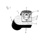
Figure 3 shows the starting and running device 1 ofFigure 1 with aclosure 5 attached to the bottom side 7 of thecasing 2. Preferably, theclosure 5 is made from a plastic material and formed in an injection molding process. - The
closure 5 is fixed by a lead-screw to thecasing 2. The lead screw is positioned in asmall opening 13 in theclosure 5. By removing the lead-screw, theclosure 5 can be reopened. This enables replacement of malfunctioning parts of the device 1, for example, a replacement of thePTC starter 3. The device 1 compriseselectrical connections electrical connections closure 5 and are configured to receive electrical terminals of the compressor. By plugging the starting and running device 1 on the compressor such that the terminals of the compressor are received in theelectrical connections - The
closure 5 covers thecompartment 10 of thecasing 2 wherein thecapacitor 3 is seated and the part of thecasing 2 wherein thePTC starter 4 is seated. Theclosure 2 does not cover theoverload protector 5. Thereby, the thermal coupling of theoverload protector 5 and the compressor is improved. Furthermore, this enables theoverload protector 5 to be replaced without re-opening theclosure 2. -
Figure 4 shows the starting and running device 1 during its assembly on aholder 17, which can be attached to the compressor motor. The starting and running device 1 is plugged onto theholder 17 such that terminals 18 are received inelectrical connections casing 2. The starter device 1 can be electrically connected to a power supply via itsconnection elements top side 8 of the starting and running device 1. Theholder 17 comprises fixation means 22, 23, 24 for fixing the device 1 on the compressor motor. Preferably, a clamp fixation of the device 1 is achieved. Moreover, the fixation means 22, 23, 24 ensure a correct configuration of the device 1 on the compressor motor and may also ensure IP protection. -
Figure 5 shows a schematic top view of the starting and running device 1 assembled on theholder 17. -
Figure 6 shows a top view of the starting and running device 1 offigure 1 attached to acompressor 19. The starting and running device 1 is seated on a holder 7, which is fixed to thecompressor 19, for example fixed by welding, seaming or clinching. -
Figure 7 shows a second embodiment of a starting and running device 1. Here, theoverload protector 5 is of a round type and, in particular, a circular cylindrical shape. The casing may be designed such that it may accommodate a round type or a flat type overload protector. - In this embodiment, the closure is snap-fitted to the casing. The casing is designed not to be reopened.
- The starting and running devices shown in
Figures 1 to 7 may be assembled as follows. First, thecapacitor 3 is placed in itscompartment 10 in thecasing 2. Thereafter, a fillingmaterial 21 is filled in thecasing 2 to cover thecapacitor coil 3 and is cured. After that, the connection wires of thecapacitor 3 are connected to terminals of thePTC starter 4, for example, by welding. After that, the terminals of thePTC starter 4 and the PTC element is placed in the casing. Then, theoverload protector 5 is placed in thecasing 2 and aclosure 6 is attached to thecasing 2, for example, by a lead screw. -
Figure 8A shows a schematic view of the electrical connection of the elements of a starting and running device for a resistance start - capacitor run motor.Figure 8B shows a corresponding circuit diagram. - The
overload protector 5 is arranged in an electrical connection between apower supply 20 and thecompressor 19. When the temperature rises beneath a maximum temperature, theoverload protector 5 disconnects thecompressor 19 from thepower supply 20. - The
PTC starter 4 is arranged in an electrical connection between thepower supply 20 and thecompressor 19 and enables a starting of thecompressor 19. - The
capacitor 3 is connected to thePTC starter 4 and thepower supply 20 and thereby to an auxiliary winding of thecompressor 19. Thereby, the performance of thecompressor 19 can be improved. -
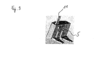
Figure 9 shows anoverload protector 5 for integration in a starting and running device. Theoverload protector 5 has a flat shape. At its top side, aconnection 11 for electrically connecting theoverload protector 5 to a power supply is provided. Theconnection 11 can pass through thecasing 2 as can be seen inFigure 2 . -
- 1 starting and running device
- 2 casing
- 3 capacitor
- 4 starter
- 5 overload protector
- 6 closure
- 7 bottom side
- 8 top side
- 9 opening
- 10 cylindrical compartment of casing
- 11 connection for overload protector
- 12 connection for starter
- 13 opening for lead screw
- 14, 15, 16 electrical connections for compressor
- 17 housing of compressor
- 18 terminal
- 19 compressor
- 20 power supply
- 21 filling agent
- 22, 23, 24 fixation element
- 25 connection wire
- 26 capacitor coil
Claims (15)
- Starting and running device for a compressor, the device comprising:a casing (2) enclosing a capacitor (3), a starter (4) and an overload protector (5), wherein the capacitor (3) is fixed to the casing (2) by a filling agent (21).
- Starting and running device according to claim 1,
wherein the capacitor (3) comprises a capacitor coil, which is directly fixed to the casing (2) by the filling agent (21). - Starting and running device according to any of claims 1 or 2,
wherein electrical connection between the capacitor (3), the starter (4) and the overload protector (5) is provided inside the casing (2). - Starting and running device according to any of claims 1 to 3,
wherein the casing (2) comprises a closure (6) configured for closing the casing (2). - Starting and running device according to any of claims 1 to 4,
wherein the casing (2) is formed as a unitary piece or the casing (2) comprising a closure (6) is formed as a unitary piece except from the closure (6). - Starting and running device according to any of claims 4 or 5,
wherein the closure (6) is configured to be closed and reopened such that a replacement of the starter (4) is enabled. - Starting and running device according to any of claims 1 to 6, wherein a placement or replacement of the overload protector (5) is enabled without opening a closure (6) of the casing (2).
- Starting and running device according to any of claims 4 to 7,
wherein the closure (6) is configured such that the overload protector (5) remains uncovered by the closure (6) when the closure (6) is attached to the casing (2). - Starting and running device according to any of claims 1 to 8, wherein the starter (4) is thermally insulated by a thermal insulation material.
- Method of assembling a starting and running device for a compressor, comprising the steps ofA) providing a capacitor (3), a starter (4) and a casing (2),B) placing the capacitor (3) in the casing (2) and fixing the capacitor (3) to the casing (2) by a filling agent (21),C) placing the starter (4) in the casing (2).
- Method of claim 10,
wherein prior to step C) the capacitor (3) is electrically connected to the starter (4). - Method of any of claims 10 or 11,
wherein in step B) the capacitor (3) placed in the casing (2) is free from a capacitor casing (2). - Method of any of claims 10 to 12,
wherein in step B) the filling agent (21) is filled in the casing (2) such that a covering of the capacitor (3) is achieved. - Method of any of claims 10 to 13, wherein the casing (2) comprises a closure (6) and wherein the method further comprises the steps of
D) closing the casing (2) with the closure (6). - Method of claim 14, wherein the overload protector (5) is placed in the casing (2) after step D).
Priority Applications (1)
| Application Number | Priority Date | Filing Date | Title |
|---|---|---|---|
| EP11150386.8A EP2475081B1 (en) | 2011-01-07 | 2011-01-07 | Starting and running device for a compressor and method of assembling a starting and running device for a compressor |
Applications Claiming Priority (1)
| Application Number | Priority Date | Filing Date | Title |
|---|---|---|---|
| EP11150386.8A EP2475081B1 (en) | 2011-01-07 | 2011-01-07 | Starting and running device for a compressor and method of assembling a starting and running device for a compressor |
Publications (2)
| Publication Number | Publication Date |
|---|---|
| EP2475081A1 true EP2475081A1 (en) | 2012-07-11 |
| EP2475081B1 EP2475081B1 (en) | 2014-10-15 |
Family
ID=44123321
Family Applications (1)
| Application Number | Title | Priority Date | Filing Date |
|---|---|---|---|
| EP11150386.8A Active EP2475081B1 (en) | 2011-01-07 | 2011-01-07 | Starting and running device for a compressor and method of assembling a starting and running device for a compressor |
Country Status (1)
| Country | Link |
|---|---|
| EP (1) | EP2475081B1 (en) |
Cited By (3)
| Publication number | Priority date | Publication date | Assignee | Title |
|---|---|---|---|---|
| CN107829923A (en) * | 2017-11-10 | 2018-03-23 | 安徽飞达电气科技有限公司 | One kind is based on plastic housing capacitor freezer compressor starter |
| CN108035871A (en) * | 2017-11-20 | 2018-05-15 | 安徽飞达电气科技有限公司 | A kind of freezer compressor integrated electric appliances starter |
| CN119122792A (en) * | 2024-10-22 | 2024-12-13 | 珠海格力电器股份有限公司 | Compressor starting system and starting method, air conditioner |
Citations (4)
| Publication number | Priority date | Publication date | Assignee | Title |
|---|---|---|---|---|
| WO1998000849A1 (en) * | 1996-07-01 | 1998-01-08 | Aerovox, Inc. | Capacitor for mounting to an electric motor |
| US6456470B1 (en) | 1999-11-15 | 2002-09-24 | Electrica S.R.L. | Starting device for compressors incorporating a start or run capacitor |
| US20040090752A1 (en) * | 2002-11-07 | 2004-05-13 | Janicek Alan Joseph | Method and apparatus for combining PTCR/OL and run capacitor |
| WO2006080695A1 (en) * | 2004-10-18 | 2006-08-03 | Texas Instruments Korea Limited | Connecting package for refrigerator compressor |
Family Cites Families (1)
| Publication number | Priority date | Publication date | Assignee | Title |
|---|---|---|---|---|
| NL252357A (en) * | 1959-11-28 | 1964-02-25 |
-
2011
- 2011-01-07 EP EP11150386.8A patent/EP2475081B1/en active Active
Patent Citations (4)
| Publication number | Priority date | Publication date | Assignee | Title |
|---|---|---|---|---|
| WO1998000849A1 (en) * | 1996-07-01 | 1998-01-08 | Aerovox, Inc. | Capacitor for mounting to an electric motor |
| US6456470B1 (en) | 1999-11-15 | 2002-09-24 | Electrica S.R.L. | Starting device for compressors incorporating a start or run capacitor |
| US20040090752A1 (en) * | 2002-11-07 | 2004-05-13 | Janicek Alan Joseph | Method and apparatus for combining PTCR/OL and run capacitor |
| WO2006080695A1 (en) * | 2004-10-18 | 2006-08-03 | Texas Instruments Korea Limited | Connecting package for refrigerator compressor |
Cited By (3)
| Publication number | Priority date | Publication date | Assignee | Title |
|---|---|---|---|---|
| CN107829923A (en) * | 2017-11-10 | 2018-03-23 | 安徽飞达电气科技有限公司 | One kind is based on plastic housing capacitor freezer compressor starter |
| CN108035871A (en) * | 2017-11-20 | 2018-05-15 | 安徽飞达电气科技有限公司 | A kind of freezer compressor integrated electric appliances starter |
| CN119122792A (en) * | 2024-10-22 | 2024-12-13 | 珠海格力电器股份有限公司 | Compressor starting system and starting method, air conditioner |
Also Published As
| Publication number | Publication date |
|---|---|
| EP2475081B1 (en) | 2014-10-15 |
Similar Documents
| Publication | Publication Date | Title |
|---|---|---|
| EP2672117B1 (en) | Motor-driven compressor | |
| CN101682236B (en) | Electric motor stator comprising a temperature controller | |
| EP2732534B1 (en) | Rotating electric machine and related packaging method | |
| US6326879B1 (en) | Thermal switch arrangement for electromagnetic coils | |
| US4791329A (en) | Motor protector mounting structure for enclosed electric compressors | |
| US11190076B2 (en) | Motor | |
| US10186928B2 (en) | Electric motor with a thermal switch positioned at a distance from a stator for household appliances | |
| US4236092A (en) | Compressor motor protection | |
| JP2997585B2 (en) | Electric machine | |
| EP2549514B1 (en) | Assembly of electric motor starter components | |
| EP2833380A1 (en) | Reactor apparatus | |
| JP2004127617A (en) | battery | |
| JP4067820B2 (en) | Secondary battery | |
| EP2475081B1 (en) | Starting and running device for a compressor and method of assembling a starting and running device for a compressor | |
| KR101495023B1 (en) | Protective device, in particular for the control electronics of a motor vehicle component | |
| EP3195450B1 (en) | Encapsulation of components and a low energy circuit for hazardous locations | |
| JP7478010B2 (en) | Rotating Electric Machine | |
| KR100894666B1 (en) | Electricals package integrating run capacitor, motor protector and motor starter | |
| EP2517336B1 (en) | A hermetic compressor comprising a connector | |
| CN106026502A (en) | Wiring terminal, electric heating hot pressing device, hot pressing method, motor and compressor | |
| JP2020167843A (en) | Rotary electric machine stator | |
| JP4794236B2 (en) | Start relay device | |
| US5852344A (en) | Enclosure for glow bulb starter used with gas discharge lamps | |
| JPH0758667B2 (en) | Thermistor integrated capacitor | |
| EP1805873B1 (en) | An electric motor |
Legal Events
| Date | Code | Title | Description |
|---|---|---|---|
| PUAI | Public reference made under article 153(3) epc to a published international application that has entered the european phase |
Free format text: ORIGINAL CODE: 0009012 |
|
| AK | Designated contracting states |
Kind code of ref document: A1 Designated state(s): AL AT BE BG CH CY CZ DE DK EE ES FI FR GB GR HR HU IE IS IT LI LT LU LV MC MK MT NL NO PL PT RO RS SE SI SK SM TR |
|
| AX | Request for extension of the european patent |
Extension state: BA ME |
|
| 17P | Request for examination filed |
Effective date: 20130111 |
|
| 17Q | First examination report despatched |
Effective date: 20130308 |
|
| GRAP | Despatch of communication of intention to grant a patent |
Free format text: ORIGINAL CODE: EPIDOSNIGR1 |
|
| INTG | Intention to grant announced |
Effective date: 20140627 |
|
| GRAS | Grant fee paid |
Free format text: ORIGINAL CODE: EPIDOSNIGR3 |
|
| GRAA | (expected) grant |
Free format text: ORIGINAL CODE: 0009210 |
|
| RIN1 | Information on inventor provided before grant (corrected) |
Inventor name: PREM, HANS Inventor name: HAENSSLER, RONALD Inventor name: SAYED, VIKAR ALI Inventor name: EGHE, RAHUL |
|
| AK | Designated contracting states |
Kind code of ref document: B1 Designated state(s): AL AT BE BG CH CY CZ DE DK EE ES FI FR GB GR HR HU IE IS IT LI LT LU LV MC MK MT NL NO PL PT RO RS SE SI SK SM TR |
|
| REG | Reference to a national code |
Ref country code: CH Ref legal event code: EP Ref country code: GB Ref legal event code: FG4D |
|
| REG | Reference to a national code |
Ref country code: IE Ref legal event code: FG4D |
|
| REG | Reference to a national code |
Ref country code: AT Ref legal event code: REF Ref document number: 692036 Country of ref document: AT Kind code of ref document: T Effective date: 20141115 |
|
| REG | Reference to a national code |
Ref country code: DE Ref legal event code: R096 Ref document number: 602011010548 Country of ref document: DE Effective date: 20141127 |
|
| REG | Reference to a national code |
Ref country code: NL Ref legal event code: VDEP Effective date: 20141015 |
|
| REG | Reference to a national code |
Ref country code: AT Ref legal event code: MK05 Ref document number: 692036 Country of ref document: AT Kind code of ref document: T Effective date: 20141015 |
|
| REG | Reference to a national code |
Ref country code: LT Ref legal event code: MG4D |
|
| PG25 | Lapsed in a contracting state [announced via postgrant information from national office to epo] |
Ref country code: NL Free format text: LAPSE BECAUSE OF FAILURE TO SUBMIT A TRANSLATION OF THE DESCRIPTION OR TO PAY THE FEE WITHIN THE PRESCRIBED TIME-LIMIT Effective date: 20141015 |
|
| PG25 | Lapsed in a contracting state [announced via postgrant information from national office to epo] |
Ref country code: PT Free format text: LAPSE BECAUSE OF FAILURE TO SUBMIT A TRANSLATION OF THE DESCRIPTION OR TO PAY THE FEE WITHIN THE PRESCRIBED TIME-LIMIT Effective date: 20150216 Ref country code: ES Free format text: LAPSE BECAUSE OF FAILURE TO SUBMIT A TRANSLATION OF THE DESCRIPTION OR TO PAY THE FEE WITHIN THE PRESCRIBED TIME-LIMIT Effective date: 20141015 Ref country code: FI Free format text: LAPSE BECAUSE OF FAILURE TO SUBMIT A TRANSLATION OF THE DESCRIPTION OR TO PAY THE FEE WITHIN THE PRESCRIBED TIME-LIMIT Effective date: 20141015 Ref country code: NO Free format text: LAPSE BECAUSE OF FAILURE TO SUBMIT A TRANSLATION OF THE DESCRIPTION OR TO PAY THE FEE WITHIN THE PRESCRIBED TIME-LIMIT Effective date: 20150115 Ref country code: LT Free format text: LAPSE BECAUSE OF FAILURE TO SUBMIT A TRANSLATION OF THE DESCRIPTION OR TO PAY THE FEE WITHIN THE PRESCRIBED TIME-LIMIT Effective date: 20141015 Ref country code: IS Free format text: LAPSE BECAUSE OF FAILURE TO SUBMIT A TRANSLATION OF THE DESCRIPTION OR TO PAY THE FEE WITHIN THE PRESCRIBED TIME-LIMIT Effective date: 20150215 |
|
| PG25 | Lapsed in a contracting state [announced via postgrant information from national office to epo] |
Ref country code: CY Free format text: LAPSE BECAUSE OF FAILURE TO SUBMIT A TRANSLATION OF THE DESCRIPTION OR TO PAY THE FEE WITHIN THE PRESCRIBED TIME-LIMIT Effective date: 20141015 Ref country code: GR Free format text: LAPSE BECAUSE OF FAILURE TO SUBMIT A TRANSLATION OF THE DESCRIPTION OR TO PAY THE FEE WITHIN THE PRESCRIBED TIME-LIMIT Effective date: 20150116 Ref country code: AT Free format text: LAPSE BECAUSE OF FAILURE TO SUBMIT A TRANSLATION OF THE DESCRIPTION OR TO PAY THE FEE WITHIN THE PRESCRIBED TIME-LIMIT Effective date: 20141015 Ref country code: HR Free format text: LAPSE BECAUSE OF FAILURE TO SUBMIT A TRANSLATION OF THE DESCRIPTION OR TO PAY THE FEE WITHIN THE PRESCRIBED TIME-LIMIT Effective date: 20141015 Ref country code: PL Free format text: LAPSE BECAUSE OF FAILURE TO SUBMIT A TRANSLATION OF THE DESCRIPTION OR TO PAY THE FEE WITHIN THE PRESCRIBED TIME-LIMIT Effective date: 20141015 Ref country code: LV Free format text: LAPSE BECAUSE OF FAILURE TO SUBMIT A TRANSLATION OF THE DESCRIPTION OR TO PAY THE FEE WITHIN THE PRESCRIBED TIME-LIMIT Effective date: 20141015 Ref country code: SE Free format text: LAPSE BECAUSE OF FAILURE TO SUBMIT A TRANSLATION OF THE DESCRIPTION OR TO PAY THE FEE WITHIN THE PRESCRIBED TIME-LIMIT Effective date: 20141015 Ref country code: RS Free format text: LAPSE BECAUSE OF FAILURE TO SUBMIT A TRANSLATION OF THE DESCRIPTION OR TO PAY THE FEE WITHIN THE PRESCRIBED TIME-LIMIT Effective date: 20141015 |
|
| REG | Reference to a national code |
Ref country code: DE Ref legal event code: R097 Ref document number: 602011010548 Country of ref document: DE |
|
| PG25 | Lapsed in a contracting state [announced via postgrant information from national office to epo] |
Ref country code: CZ Free format text: LAPSE BECAUSE OF FAILURE TO SUBMIT A TRANSLATION OF THE DESCRIPTION OR TO PAY THE FEE WITHIN THE PRESCRIBED TIME-LIMIT Effective date: 20141015 Ref country code: DK Free format text: LAPSE BECAUSE OF FAILURE TO SUBMIT A TRANSLATION OF THE DESCRIPTION OR TO PAY THE FEE WITHIN THE PRESCRIBED TIME-LIMIT Effective date: 20141015 Ref country code: EE Free format text: LAPSE BECAUSE OF FAILURE TO SUBMIT A TRANSLATION OF THE DESCRIPTION OR TO PAY THE FEE WITHIN THE PRESCRIBED TIME-LIMIT Effective date: 20141015 Ref country code: RO Free format text: LAPSE BECAUSE OF FAILURE TO SUBMIT A TRANSLATION OF THE DESCRIPTION OR TO PAY THE FEE WITHIN THE PRESCRIBED TIME-LIMIT Effective date: 20141015 Ref country code: SK Free format text: LAPSE BECAUSE OF FAILURE TO SUBMIT A TRANSLATION OF THE DESCRIPTION OR TO PAY THE FEE WITHIN THE PRESCRIBED TIME-LIMIT Effective date: 20141015 |
|
| PLBE | No opposition filed within time limit |
Free format text: ORIGINAL CODE: 0009261 |
|
| STAA | Information on the status of an ep patent application or granted ep patent |
Free format text: STATUS: NO OPPOSITION FILED WITHIN TIME LIMIT |
|
| REG | Reference to a national code |
Ref country code: CH Ref legal event code: PL |
|
| PG25 | Lapsed in a contracting state [announced via postgrant information from national office to epo] |
Ref country code: LU Free format text: LAPSE BECAUSE OF FAILURE TO SUBMIT A TRANSLATION OF THE DESCRIPTION OR TO PAY THE FEE WITHIN THE PRESCRIBED TIME-LIMIT Effective date: 20150107 Ref country code: IT Free format text: LAPSE BECAUSE OF FAILURE TO SUBMIT A TRANSLATION OF THE DESCRIPTION OR TO PAY THE FEE WITHIN THE PRESCRIBED TIME-LIMIT Effective date: 20141015 |
|
| 26N | No opposition filed |
Effective date: 20150716 |
|
| GBPC | Gb: european patent ceased through non-payment of renewal fee |
Effective date: 20150115 |
|
| PG25 | Lapsed in a contracting state [announced via postgrant information from national office to epo] |
Ref country code: MC Free format text: LAPSE BECAUSE OF FAILURE TO SUBMIT A TRANSLATION OF THE DESCRIPTION OR TO PAY THE FEE WITHIN THE PRESCRIBED TIME-LIMIT Effective date: 20141015 |
|
| PG25 | Lapsed in a contracting state [announced via postgrant information from national office to epo] |
Ref country code: GB Free format text: LAPSE BECAUSE OF NON-PAYMENT OF DUE FEES Effective date: 20150115 Ref country code: CH Free format text: LAPSE BECAUSE OF NON-PAYMENT OF DUE FEES Effective date: 20150131 Ref country code: LI Free format text: LAPSE BECAUSE OF NON-PAYMENT OF DUE FEES Effective date: 20150131 |
|
| REG | Reference to a national code |
Ref country code: FR Ref legal event code: ST Effective date: 20150930 |
|
| REG | Reference to a national code |
Ref country code: IE Ref legal event code: MM4A |
|
| PG25 | Lapsed in a contracting state [announced via postgrant information from national office to epo] |
Ref country code: FR Free format text: LAPSE BECAUSE OF NON-PAYMENT OF DUE FEES Effective date: 20150202 |
|
| PG25 | Lapsed in a contracting state [announced via postgrant information from national office to epo] |
Ref country code: IE Free format text: LAPSE BECAUSE OF NON-PAYMENT OF DUE FEES Effective date: 20150107 |
|
| PG25 | Lapsed in a contracting state [announced via postgrant information from national office to epo] |
Ref country code: SI Free format text: LAPSE BECAUSE OF FAILURE TO SUBMIT A TRANSLATION OF THE DESCRIPTION OR TO PAY THE FEE WITHIN THE PRESCRIBED TIME-LIMIT Effective date: 20141015 |
|
| PG25 | Lapsed in a contracting state [announced via postgrant information from national office to epo] |
Ref country code: MT Free format text: LAPSE BECAUSE OF FAILURE TO SUBMIT A TRANSLATION OF THE DESCRIPTION OR TO PAY THE FEE WITHIN THE PRESCRIBED TIME-LIMIT Effective date: 20141015 |
|
| PG25 | Lapsed in a contracting state [announced via postgrant information from national office to epo] |
Ref country code: SM Free format text: LAPSE BECAUSE OF FAILURE TO SUBMIT A TRANSLATION OF THE DESCRIPTION OR TO PAY THE FEE WITHIN THE PRESCRIBED TIME-LIMIT Effective date: 20141015 Ref country code: BG Free format text: LAPSE BECAUSE OF FAILURE TO SUBMIT A TRANSLATION OF THE DESCRIPTION OR TO PAY THE FEE WITHIN THE PRESCRIBED TIME-LIMIT Effective date: 20141015 Ref country code: HU Free format text: LAPSE BECAUSE OF FAILURE TO SUBMIT A TRANSLATION OF THE DESCRIPTION OR TO PAY THE FEE WITHIN THE PRESCRIBED TIME-LIMIT; INVALID AB INITIO Effective date: 20110107 |
|
| PG25 | Lapsed in a contracting state [announced via postgrant information from national office to epo] |
Ref country code: TR Free format text: LAPSE BECAUSE OF FAILURE TO SUBMIT A TRANSLATION OF THE DESCRIPTION OR TO PAY THE FEE WITHIN THE PRESCRIBED TIME-LIMIT Effective date: 20141015 |
|
| PG25 | Lapsed in a contracting state [announced via postgrant information from national office to epo] |
Ref country code: BE Free format text: LAPSE BECAUSE OF FAILURE TO SUBMIT A TRANSLATION OF THE DESCRIPTION OR TO PAY THE FEE WITHIN THE PRESCRIBED TIME-LIMIT Effective date: 20141015 |
|
| PG25 | Lapsed in a contracting state [announced via postgrant information from national office to epo] |
Ref country code: MK Free format text: LAPSE BECAUSE OF FAILURE TO SUBMIT A TRANSLATION OF THE DESCRIPTION OR TO PAY THE FEE WITHIN THE PRESCRIBED TIME-LIMIT Effective date: 20141015 |
|
| PG25 | Lapsed in a contracting state [announced via postgrant information from national office to epo] |
Ref country code: AL Free format text: LAPSE BECAUSE OF FAILURE TO SUBMIT A TRANSLATION OF THE DESCRIPTION OR TO PAY THE FEE WITHIN THE PRESCRIBED TIME-LIMIT Effective date: 20141015 |
|
| REG | Reference to a national code |
Ref country code: DE Ref legal event code: R082 Ref document number: 602011010548 Country of ref document: DE Representative=s name: EPPING HERMANN FISCHER PATENTANWALTSGESELLSCHA, DE Ref country code: DE Ref legal event code: R081 Ref document number: 602011010548 Country of ref document: DE Owner name: TDK ELECTRONICS AG, DE Free format text: FORMER OWNER: EPCOS AG, 81669 MUENCHEN, DE |
|
| P01 | Opt-out of the competence of the unified patent court (upc) registered |
Effective date: 20230521 |
|
| PGFP | Annual fee paid to national office [announced via postgrant information from national office to epo] |
Ref country code: DE Payment date: 20260123 Year of fee payment: 16 |