EP2474994B1 - Automatic spacers mounting system for field emission display and method of automatically mounting spacers - Google Patents
Automatic spacers mounting system for field emission display and method of automatically mounting spacers Download PDFInfo
- Publication number
- EP2474994B1 EP2474994B1 EP11185213.3A EP11185213A EP2474994B1 EP 2474994 B1 EP2474994 B1 EP 2474994B1 EP 11185213 A EP11185213 A EP 11185213A EP 2474994 B1 EP2474994 B1 EP 2474994B1
- Authority
- EP
- European Patent Office
- Prior art keywords
- spacers
- pallet
- panel
- posture changing
- horizontal
- Prior art date
- Legal status (The legal status is an assumption and is not a legal conclusion. Google has not performed a legal analysis and makes no representation as to the accuracy of the status listed.)
- Not-in-force
Links
Images






Classifications
-
- H—ELECTRICITY
- H01—ELECTRIC ELEMENTS
- H01J—ELECTRIC DISCHARGE TUBES OR DISCHARGE LAMPS
- H01J9/00—Apparatus or processes specially adapted for the manufacture, installation, removal, maintenance of electric discharge tubes, discharge lamps, or parts thereof; Recovery of material from discharge tubes or lamps
- H01J9/24—Manufacture or joining of vessels, leading-in conductors or bases
-
- H—ELECTRICITY
- H01—ELECTRIC ELEMENTS
- H01J—ELECTRIC DISCHARGE TUBES OR DISCHARGE LAMPS
- H01J9/00—Apparatus or processes specially adapted for the manufacture, installation, removal, maintenance of electric discharge tubes, discharge lamps, or parts thereof; Recovery of material from discharge tubes or lamps
- H01J9/46—Machines having sequentially arranged operating stations
- H01J9/48—Machines having sequentially arranged operating stations with automatic transfer of workpieces between operating stations
-
- H—ELECTRICITY
- H01—ELECTRIC ELEMENTS
- H01J—ELECTRIC DISCHARGE TUBES OR DISCHARGE LAMPS
- H01J1/00—Details of electrodes, of magnetic control means, of screens, or of the mounting or spacing thereof, common to two or more basic types of discharge tubes or lamps
- H01J1/02—Main electrodes
- H01J1/30—Cold cathodes, e.g. field-emissive cathode
-
- H—ELECTRICITY
- H01—ELECTRIC ELEMENTS
- H01J—ELECTRIC DISCHARGE TUBES OR DISCHARGE LAMPS
- H01J29/00—Details of cathode-ray tubes or of electron-beam tubes of the types covered by group H01J31/00
- H01J29/86—Vessels; Containers; Vacuum locks
- H01J29/864—Spacers between faceplate and backplate of flat panel cathode ray tubes
-
- H—ELECTRICITY
- H01—ELECTRIC ELEMENTS
- H01J—ELECTRIC DISCHARGE TUBES OR DISCHARGE LAMPS
- H01J31/00—Cathode ray tubes; Electron beam tubes
- H01J31/08—Cathode ray tubes; Electron beam tubes having a screen on or from which an image or pattern is formed, picked up, converted, or stored
- H01J31/10—Image or pattern display tubes, i.e. having electrical input and optical output; Flying-spot tubes for scanning purposes
- H01J31/12—Image or pattern display tubes, i.e. having electrical input and optical output; Flying-spot tubes for scanning purposes with luminescent screen
- H01J31/123—Flat display tubes
- H01J31/125—Flat display tubes provided with control means permitting the electron beam to reach selected parts of the screen, e.g. digital selection
-
- H—ELECTRICITY
- H01—ELECTRIC ELEMENTS
- H01J—ELECTRIC DISCHARGE TUBES OR DISCHARGE LAMPS
- H01J9/00—Apparatus or processes specially adapted for the manufacture, installation, removal, maintenance of electric discharge tubes, discharge lamps, or parts thereof; Recovery of material from discharge tubes or lamps
- H01J9/24—Manufacture or joining of vessels, leading-in conductors or bases
- H01J9/241—Manufacture or joining of vessels, leading-in conductors or bases the vessel being for a flat panel display
- H01J9/242—Spacers between faceplate and backplate
-
- H—ELECTRICITY
- H01—ELECTRIC ELEMENTS
- H01J—ELECTRIC DISCHARGE TUBES OR DISCHARGE LAMPS
- H01J2329/00—Electron emission display panels, e.g. field emission display panels
- H01J2329/86—Vessels
- H01J2329/8625—Spacing members
-
- Y—GENERAL TAGGING OF NEW TECHNOLOGICAL DEVELOPMENTS; GENERAL TAGGING OF CROSS-SECTIONAL TECHNOLOGIES SPANNING OVER SEVERAL SECTIONS OF THE IPC; TECHNICAL SUBJECTS COVERED BY FORMER USPC CROSS-REFERENCE ART COLLECTIONS [XRACs] AND DIGESTS
- Y10—TECHNICAL SUBJECTS COVERED BY FORMER USPC
- Y10T—TECHNICAL SUBJECTS COVERED BY FORMER US CLASSIFICATION
- Y10T156/00—Adhesive bonding and miscellaneous chemical manufacture
- Y10T156/10—Methods of surface bonding and/or assembly therefor
-
- Y—GENERAL TAGGING OF NEW TECHNOLOGICAL DEVELOPMENTS; GENERAL TAGGING OF CROSS-SECTIONAL TECHNOLOGIES SPANNING OVER SEVERAL SECTIONS OF THE IPC; TECHNICAL SUBJECTS COVERED BY FORMER USPC CROSS-REFERENCE ART COLLECTIONS [XRACs] AND DIGESTS
- Y10—TECHNICAL SUBJECTS COVERED BY FORMER USPC
- Y10T—TECHNICAL SUBJECTS COVERED BY FORMER US CLASSIFICATION
- Y10T156/00—Adhesive bonding and miscellaneous chemical manufacture
- Y10T156/10—Methods of surface bonding and/or assembly therefor
- Y10T156/1089—Methods of surface bonding and/or assembly therefor of discrete laminae to single face of additional lamina
-
- Y—GENERAL TAGGING OF NEW TECHNOLOGICAL DEVELOPMENTS; GENERAL TAGGING OF CROSS-SECTIONAL TECHNOLOGIES SPANNING OVER SEVERAL SECTIONS OF THE IPC; TECHNICAL SUBJECTS COVERED BY FORMER USPC CROSS-REFERENCE ART COLLECTIONS [XRACs] AND DIGESTS
- Y10—TECHNICAL SUBJECTS COVERED BY FORMER USPC
- Y10T—TECHNICAL SUBJECTS COVERED BY FORMER US CLASSIFICATION
- Y10T156/00—Adhesive bonding and miscellaneous chemical manufacture
- Y10T156/17—Surface bonding means and/or assemblymeans with work feeding or handling means
- Y10T156/1702—For plural parts or plural areas of single part
Definitions
- Apparatuses and methods consistent with exemplary embodiments relate to an automatic spacers mounting system capable of automatically mounting spacers on a panel of a field emission display.
- a field emission display has a top panel and a bottom panel that are spaced apart from each other, and a space between the top and bottom panels is sealed in a vacuum. Therefore, many spacers are used to uniformly maintain the gap and the vacuum between the top and bottom panels.
- a spacer may have a cylindrical shape.
- a method of mounting spacers on the field emission display may include a worker individually mounting spacers on the field emission display with tweezers. The method takes a long time and provides a low yield.
- a plurality of spacers are picked up and placed by a chuck.
- the method is configured so that L spacers are mounted on the panel M times. Accordingly, many spacers are set in a vertical position one by one using a bowl feeder and a linear feeder, and a gripper is used to pick up and place the spacers to mount them on the field emission display.
- this method takes a long time. Also, if the spacers have a high aspect ratio, it is difficult to quickly mount the spacers.
- JP2002-063859 uses vacuum suction to arrange spacers.
- One or more embodiments may overcome the above drawbacks and other problems associated with the related art arrangement.
- One or more embodiments provide an automatic spacers mounting system capable of mounting many spacers having a high aspect ratio on a panel at a high speed and a mounting method using the same.
- an automatic spacers mounting system including a horizontal arraying device configured to hole a plurality of spacers in a horizontal arraying pallet in a horizontal direction; a reversing device including a posture changing pallet and an open-close shutter in a layered structure.
- the reversing device couples the horizontal arraying pallet to the posture changing pallet such that the posture changing pallet faces the horizontal arraying pallet, and rotates the posture changing pallet by 180 degrees with the coupled horizontal arraying pallet.
- An inserting guide having a plurality of guiding holes is disposed above a panel with sprayed glue disposed on a working table.
- a first loader carries the reversing device above the inserting guide and inserts the plurality of spacers into the plurality of guiding holes.
- a pressing chuck includes a plurality of pressing pins to be inserted in the plurality of guiding holes and to press the spacers against the panel.
- a second loader carries the pressing chuck above the inserting guide and inserts the plurality of pressing pins into the plurality of guiding holes; and a controller controls the reversing device, the first loader and the second loader to mount the plurality of spacers on the panel.
- the horizontal arraying pallet may include a plurality of elongated grooves formed at a predetermined interval and in which the plurality of spacers is horizontally inserted.
- the horizontal arraying pallet may include a plurality of elongated grooves formed at a predetermined interval and in which the plurality of spacers is horizontally inserted.
- the horizontal arraying device may be configured to allow the horizontal arraying pallet to perform a seesaw motion and to apply vibration to the horizontal arraying pallet.
- the reversing device may include a reversing frame in which the posture changing pallet and the open-close shutter are layered; and a rotating unit to rotate the reversing frame.
- the reversing frame may include pallet fixing portions to fix the horizontal arraying pallet to the posture changing pallet and a shutter driving portion to move the open-close shutter with respect to the posture changing pallet.
- the posture changing pallet may include a plurality of posture changing holes.
- Each of the posture changing holes may include an inlet portion corresponding to the spacer in a horizontal state, an outlet portion corresponding to the spacer in a vertical state and a curved portion connecting the inlet portion and the outlet portion to guide the spacer from the horizontal state to the vertical state.
- the open-close shutter may include a plurality of blocking portions formed to correspond to the outlet portions of the plurality of posture changing holes of the posture changing pallet and a plurality of through holes, each formed at a side of one of the plurality of blocking portions, the plurality of through holes being holes which the spacers discharged from the outlet portion passes.
- the blocking portion or the through holes may be located below the outlet portions of the posture changing holes.
- a top end of each of the plurality of guiding holes of the inserting guide may be funnel-shaped.
- Each of the plurality of pressing pins may be a spring pin.
- the horizontal arraying pallet may be configured to array a number of spacers corresponding to a number of spacers that will be mounted on the panel at one time.
- the panel may be divided into four equal parts and the controller may mount 1/4 of the spacers on each of the four equal parts at a time.
- the automatic spacers mounting system may include a panel carrying unit to automatically load and unload the panel to and from the working table.
- the automatic spacers mounting system may include a glue dispensing apparatus disposed at a side of the panel carrying unit to spray glue onto a plurality of positions of the panel on which the plurality of spacers is to be mounted.
- a method of automatically mounting spacers may include; spraying glue onto a plurality of positions on a panel on which a plurality of spacers is to be mounted; loading the panel with sprayed glue onto a working table below an inserting guide of an automatic spacers mounting apparatus; arraying the plurality of spacers on a horizontal arraying pallet in a horizontal direction using a horizontal arraying device; coupling the horizontal arraying pallet to a posture changing pallet of a reversing device; allowing the reversing device to rotate by 180 degrees so that the plurality of spacers is moved into vertical positions; moving the reversing device above the inserting guide; allowing the plurality of spacers to fall into a plurality of guiding holes of the inserting guide so that the spacers inserted into the plurality of guiding holes of the inserting guide contact the glue on the panel; moving a pressing chuck above the inserting guide to press the spacers inserted in the guiding holes; and unloading the
- the spraying glue onto the plurality of positions of the panel and the arraying the plurality of spacers on the horizontal arraying pallet may be simultaneously performed.
- the reversing device rotates the horizontal arraying pallet by 180 degrees, the position of each of the spacers is changed from a horizontal position to a vertical position while the spacers pass through a plurality of posture changing holes of the posture changing pallet.
- the inserting guide may be divided into four equal parts, and the moving the reversing device above the inserting guide may comprise placing the reversing device in order above a first part to a fourth part of the inserting guide.
- FIG. 1 is a layout schematically illustrating an automatic spacers mounting system according to an exemplary embodiment
- FIG. 2 is a conceptual view illustrating a glue dispensing apparatus used in an automatic spacers mounting system according to an exemplary embodiment
- FIG. 3 is a view conceptually illustrating a state in which the glue dispensing apparatus of FIG. 2 dispenses glue on the panel;
- FIG. 4 is a perspective view illustrating the panel on which the glue is dispensed at a predetermined interval by the glue dispensing apparatus of FIG. 2 ;
- FIG. 5 is a perspective view schematically illustrating an automatic spacers mounting apparatus according to an exemplary embodiment
- FIG. 6 is a perspective view illustrating a horizontal arraying device of the automatic spacers mounting system of FIG. 1 ;
- FIG. 7 is a view conceptually illustrating a state in which the horizontal arraying device of FIG. 6 arrays spacers;
- FIG. 8 is a perspective view illustrating a reversing device of the automatic spacers mounting system of FIG. 1 ;
- FIG. 9 is a sectional view illustrating a horizontal arraying pallet coupled to the reversing device of FIG. 8 ;
- FIG. 10A is a perspective view illustrating the horizontal arraying pallet of FIG. 9 ;
- FIG. 10B is an enlarged perspective view illustrating a portion H1 of FIG. 10A ;
- FIG. 11A is a perspective view illustrating a posture changing pallet of FIG. 9 ;
- FIG. 11B is an enlarged perspective view illustrating a portion H2 of FIG. 11A ;
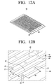
- FIG. 12A is a perspective view illustrating a open-close shutter of FIG. 9 ;
- FIG. 12B is an enlarged perspective view illustrating a portion H3 of FIG. 12A ;
- FIGS. 13 and 14 are a partially sectional view for explaining an operation of the open-close shutter of FIG. 12A ;
- FIG. 15 is a perspective view illustrating a pressing chuck of the automatic spacers mounting system of FIG. 1 ;
- FIG. 16 is a partially sectional view conceptually illustrating a relationship of a horizontal arraying pallet, a posture changing pallet, and an open-close shutter when the horizontal arraying pallet is coupled to the reversing device;
- FIG. 17 is a partially sectional view conceptually illustrating a state in which the revering device of FIG. 16 is rotated by 180 degrees;
- FIG. 18 is a partially sectional view conceptually illustrating a state in which a panel is loaded between a working table and an inserting guide
- FIG. 19 is a partially sectional view conceptually illustrating a state in which the reversing device of FIG. 17 is located above the inserting guide of FIG. 18 ;
- FIG. 20 is a partially sectional view conceptually illustrating a state in which an open-close shutter of the reversing device operates so that spacers are adhered to the panel through the inserting guide;
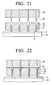
- FIG. 21 is a partially sectional view conceptually illustrating a state in which a pressing chuck is located above the inserting guide after the revering device is moved;
- FIG. 22 is a partially sectional view conceptually illustrating a state in which the pressing chuck moves downward to press spacers against the panel;
- FIG. 23 is a perspective view conceptually illustrating a panel on which spacers are mounted.
- FIG. 24 is a flow chart illustrating a method of automatically mounting spacers according to an exemplary embodiment.
- FIG. 1 is a layout schematically illustrating an automatic spacers mounting system according to an exemplary embodiment
- FIG. 2 is a conceptual view illustrating a glue dispensing apparatus used in an automatic spacers mounting system according to an exemplary embodiment.
- the automatic spacers mounting system 1 is an apparatus that automatically mounts a number of spacers S on a panel 9 of an FED, and, as illustrated in FIG. 1 , may include a glue dispensing apparatus 2 and a automatic spacers mounting apparatus 3.
- the glue dispensing apparatus 2 is an apparatus that dispenses a predetermined amount of glue at a plurality of positions on the panel 9 of the field emission display on which the spacers are to be mounted. In the case of a 46-inch panel, 1176 spacers are mounted on the panel. A conceptual view of the glue dispensing apparatus 2 is illustrated in FIG. 2 .
- the glue dispensing apparatus 2 may include a base 11, a gun head 15 on which a plurality of glue guns 13 are disposed, and a gun moving unit 17 to move the gun head 15 with respect to the base 11.
- the panel 9 is loaded on the base 11 of the glue dispensing apparatus 2.
- a panel loading apparatus may be included to automatically load and unload the panel 9 to and from the base 11 of the glue dispensing apparatus 2.
- the plurality of glue guns 13 are disposed at a predetermined interval on the gun head 15.
- FIG. 2 illustrates the glue dispensing apparatus 2 having four glue guns 13; however, this is only one example. The number of the glue guns 13 may be determined as necessary. Intervals between the plurality of glue guns 13 may be equal to a multiple of a pitch D2 between the plurality of spacers S that will be mounted on the panel 9.
- FIG. 3 illustrates a case in which the interval W between the glue guns 13 is two times of the pitch D2 between the spacers S.
- the gun moving unit 17 is formed to move the gun head 15 in two directions, namely, in an X direction and a Y direction with respect to the base 11.
- the glue guns 13 are upwardly spaced apart from the panel 9 by a predetermined distance and can spray a predetermined amount of glue in a dot on the panel 9.
- the amount of glue G sprayed by the glue gun 13 may be determined as the amount needed to fix the spacer S on the panel 9.
- the glue dispensing apparatus 2 divides the panel 9 into predetermined areas, moves the gun head 15, on which the plurality of glue guns 13 are disposed, in X and Y directions, and sprays the glue G in dots at positions at which the spacers S are mounted all over the panel 9.
- the sprayed glue forms a plurality of glue spots G on a top surface of the panel 9.
- the plurality of glue spots G are formed at the same intervals D 1 and D2 in the X and Y directions as the pitches of the spacers S to be mounted. In FIG. 4 , for convenience of drawing, only some glue spots G are enlarged and illustrated. In fact, 1176 glue spots G may be formed on a 46-inch panel 9.
- the plurality of glue guns 13 may be controlled by a trigger signal.
- the panel 9 on which the glue G is sprayed by the glue dispensing apparatus 2 is loaded onto the automatic spacers mounting apparatus 3 that will be described below.
- FIG. 5 is a perspective view schematically illustrating the automatic spacers mounting apparatus 3 according to an exemplary embodiment.
- the automatic spacers mounting apparatus 3 may include a horizontal arraying device 20, a reversing device 30, an inserting guide 50, a working table 55 ( FIG. 18 ), a first loader 60, a second loader 70, a pressing chuck 80, and a controller 90 ( FIG. 1 ).
- the horizontal arraying device 20 is an apparatus that allows the plurality of spacers S to be arrayed in a horizontal direction on a horizontal arraying pallet 21.
- the horizontal arraying device 20 includes a seesaw table 23 and an operating portion 24.
- On the seesaw table 23 is detachably mounted the horizontal arraying pallet 21.
- the operating portion 24 drives the seesaw table 23 to perform a seesaw motion as illustrated in FIG. 7 .
- the operating portion 24 can apply vibrations of a predetermined frequency to the seesaw table 23. Therefore, the horizontal arraying pallet 21 mounted on the seesaw table 23 can perform a seesaw motion, and simultaneously vibrate at a predetermined frequency.
- the horizontal arraying pallet 21 has a plurality of elongated grooves 21-1 in which a spacer S can be received in a horizontal state.
- the horizontal arraying pallet 21 has a number of elongated grooves 21-1 corresponding to the number of spacers S, so that all of the spacers S required for the panel 9 can be received in the horizontal arraying pallet 21.
- the elongated grooves 21-1 may be formed to have cross-sections corresponding to the shape of the spacer S.
- the elongated grooves 21-1 are configured so that four elongated grooves 21-1 form one group.
- the four elongated grooves 21-1 of each of two nearby groups have the same interval as the pitch of plurality of spacers that will be mounted on the panel 9.
- an interval d2 between a first elongated groove A1 among four elongated grooves A1-A4 of A group and a first elongated groove B1 among four elongated grooves B1-B4 of B group has the same size as that of a spacer pitch D2.
- an interval d2 between each of the second, third, and fourth elongated grooves A2, A3 and A4 of the A group and each of the second, third, and fourth elongated grooves B2, B3 and B4 of the B group is the same size as the spacer pitch D2.
- an interval d1 between the A group and a C group perpendicular to the A group is the same size as that of a spacer pitch D1 in a corresponding direction.
- the spacer pitch means intervals D1 and D2 (see FIG. 4 ) between spacers S in two directions that are perpendicular to each other when the spacers S are mounted on the panel 9.
- the number of elongated groove groups A, B, and C formed on the horizontal arraying pallet 21 is 1/4 of the total number of spacers S. Therefore, the horizontal arraying pallet 21 on which the elongated groove groups A, B and C are formed has an area corresponding to 1/4 of an area of the panel 9.
- a pallet carrying unit 25 may be disposed at a side of the horizontal arraying device 20.
- the pallet carrying unit 25 carries the horizontal arraying pallet 21 on which the spacers S are loaded to a pallet loading portion 26 below the first loader 60.
- the pallet carrying unit 25 may be a conveyor.
- In the horizontal arraying device 20 may be disposed a device (not illustrated) that automatically carries the horizontal arraying pallet 21 to the pallet carrying unit 25.
- the pallet carrying unit 25 places the horizontal arraying pallet 21 in the pallet loading portion 26.
- FIG. 8 is a perspective view illustrating the reversing device 30 of the automatic spacers mounting system 1 according to an exemplary embodiment.
- the reversing device 30 is an apparatus that allows the plurality of spacers S arrayed horizontally to be arrayed vertically.
- the reversing device 30 includes a reversing frame 31 and a rotating unit 32.
- the reversing frame 31 holds a posture changing pallet 40 on top of an open-close shutter 45.
- the posture changing pallet 40 has a size corresponding to the size of the horizontal arraying pallet 21, and has a plurality of posture changing holes 41 as illustrated in FIGS. 11A and 11B .
- the number of elongated grooves 21-1 formed in the horizontal arraying pallet 21 is the same as the number of the posture changing holes 41 formed in the posture changing pallet 40.
- posture changing hole groups A', B' and C' each of which includes four posture changing holes A'1-A'4, corresponding to the elongated groove groups A, B and C of the horizontal arraying pallet 21. Therefore, the elongated grooves 21-1 of the horizontal arraying pallet 21 and the posture changing holes 41 of the posture changing pallet 40 correspond one to one.
- the posture changing holes 41 allow the spacers S arrayed horizontally in the elongated grooves 21-1 of the horizontal arraying pallet 21 to be arrayed in a vertical direction.
- the posture changing holes 41 are configured to include an inlet portion 41a that corresponds to a size of the spacer S in a horizontal state to receive the spacer S in a horizontal state, a circular outlet portion 41b having an inner diameter through which the spacer S can pass, corresponding to the spacer S in a vertical state, and a curved portion 41c that connects the inlet portion and the outlet portion 41b and guides the spacer S to change its posture from a horizontal state to a vertical state.
- the curved portion 41c is formed to have a curvature sufficient to erect the falling spacer S from the horizontal state to a vertical state. Therefore, when the reversing device 30 rotates by 180 degrees, the spacers S which are disposed horizontally in the elongated grooves 21-1 of the horizontal arraying pallet 21 are moved into a vertical state while passing through the posture changing holes 41.
- FIG. 9 illustrates a state in which the horizontal arraying pallet 21 has been connected to the posture changing pallet 40 and then rotated by 180 degrees.
- the posture changing pallet 40 is fixed to the reversing frame 31, and the open-close shutter 45 is disposed in the reversing frame 31 to face one surface of the posture changing pallet 40 and to position in at least five points with respect to the posture changing pallet 40.
- a shutter driving portion 35 that moves the open-close shutter 45 and determines a position of the open-close shutter 45 is disposed on opposite sides of the reversing frame 31.
- the shutter driving portion 35 may use a servo motor for accurate positioning.
- a moving distance of the open-close shutter 45 is determined to selectively open or close the posture changing holes 41 of the posture changing pallet 40.
- a surface opposite to the surface of the posture changing pallet 40 on which the open-close shutter 45 is disposed is exposed and is connected to the horizontal arraying pallet 21.
- the open-close shutter 45 includes a plurality of through holes 46.
- Each of the through holes 46 is formed at a position corresponding to an outlet portion 41b of one of the four posture changing holes A'1, A'2, A'3 and A'4 of each of the plurality of posture changing hole groups A' and B' of the posture changing pallet 40. Therefore, the interval between two nearby through holes A" and B" in FIG. 12B corresponds to the interval between outlet portions 41b of two posture changing holes 41 corresponding to each other among nearby posture changing hole groups A' and B' of the posture changing pallet 40. For example, the interval d2 between two nearby through holes A" and B" of the open-close shutter 45 of FIG.
- a blocking portion 47 which blocks the outlet portion of the posture changing holes 41 is provided between two nearby through holes A" and B" among the plurality of through holes 46. Therefore, when the through holes 46 of the open-close shutter 45 are aligned with the outlet portion 41b of the posture changing pallet 40, the spacer S can pass through the open-close shutter 45, and when the blocking portion 47 is disposed in front of the outlet portion 41b, the spacer S cannot pass through the open-close shutter 45. Also, as illustrated in FIG.
- the plurality of through holes 46 and the blocking portions 47 may be formed on portions 48 which project from a shutter plate 45a of the open-close shutter 45. Since friction between the open-close shutter 45 and the posture changing pallet 40 may be thereby decreased, the open-close shutter 45 can operate smoothly. Further, a plurality of openings 49 may be formed between projecting portions 48 of the open-close shutter 45. The plurality of openings 49 allows the leaked spacers S to be discharged so as to prevent the leaked spacers S from getting between the open-close shutter 45 and the posture changing pallet 40 and can reduce the weight of the open-close shutter 45.
- the open-close shutter 45 always blocks all the outlet portions 41b of the four posture changing holes 41 of the posture changing hole group of the posture changing pallet 40 before receiving a open signal from the controller 90.
- the open-close shutter 45 as illustrated in FIG. 13 , is located in a first position (original position) in which the blocking portion 47 is disposed below the posture changing hole groups A' and B' of the posture changing pallet 40.
- the open-close shutter 45 moves to a second position in which the through hole 46 is disposed below the first posture changing hole A' 1 of the posture changing hole group A'.
- the spacer S that stands vertically at the outlet portion 41b of the first posture changing hole A'1 falls into a vertical state.
- the other three posture changing holes A'2, A'3 and A'4 are blocked by the blocking portion 47 so that the spacers S do not fall down.
- the open-close shutter 45 receives a second open signal, the open-close shutter 45 moves to a third position in which the through hole 46 is disposed below a second posture changing hole A'2.
- the spacer S in the second posture changing hole A'2 falls and the other two posture changing holes A'3 and A'4 are blocked by the blocking portion 47 so that the spacers S do not fall down.
- the open-close shutter 45 When the open-close shutter 45 receives third and fourth open signals, the open-close shutter 45 moves to fourth and fifth positions in which the through hole 46 is disposed below the third posture changing holes A'3 and the fourth posture changing hole A'4, respectively, so that the spacers S fall down. After the open-close shutter 45 moves to the fifth position, the open-close shutter 45 again returns to the first position (the original position).
- the rotating unit 32 rotates the reversing frame 31 by 180 degrees.
- the rotating unit 32 is formed substantially in a ' ⁇ ' shape and includes a supporting frame 32-1 supporting a rotation of the reversing frame 31 and a rotating portion 32-2 that is disposed at a side of the supporting frame 32-1 and allows the reversing frame 31 to rotate.
- Various driving members can be used as the rotating portion 32-2 as long as they can rotate the reversing frame 31 by 180 degrees. Therefore, detailed explanations thereof will be omitted.
- pallet fixing portions 36 that fix the horizontal arraying pallet 21 with respect to the posture changing pallet 40.
- four pallet fixing portions 36 are disposed at the reversing frame 31. Therefore, even when the reversing frame 31 rotates and moves, the horizontal arraying pallet 21 is not separated from the posture changing pallet 40.
- the horizontal arraying pallet 21 and posture changing pallet 40 have the same size and each have a number of elongated grooves 21-1 and posture changing holes 41 corresponding to the spacers S required for the panel 9.
- the horizontal arraying pallet 21 and the posture changing pallet 40 are formed to have a size corresponding to one part of the four equal parts 9-1, 9-2, 9-3 and 9-4 of the panel 9, namely, 1/4 of the area of the panel 9.
- the open-close shutter 45 has approximately the same size as that of the posture changing pallet 40 and has the same number of through holes 46 as the number of spacers S mounted on one part of the four equal parts 9-1, 9-2, 9-3 and 9-4 of the panel 9. Therefore, all of the spacers S of the panel 9 received in the horizontal arraying pallet 21 can be mounted in order on the four equal parts 9-1, 9-2, 9-3 and 9-4 of the panel 9 by using the open-close shutter 45.
- each of the horizontal arraying pallet 21, the posture changing pallet 40, and the open-close shutter 45 may be properly determined in consideration of the size of the panel 9 and the automatic spacers mounting system 1.
- a horizontal arraying pallet 21 having a size of approximately 1/4 of the panel 9 is used for purposes of description. However, this is only one example and does not limit the size of the horizontal arraying pallet 21.
- the inserting guide 50 guides the spacer S falling from the posture changing pallet 40 to be placed on the panel 9 while maintaining a vertical posture, and is disposed at an approximate center of a main base 91.
- An inserting guide 50 is formed of a planar plate having a size corresponding to the total area of the panel 9.
- the inserting guide 50 has a plurality of guiding holes 51 of the same number as the number of spacers S that will be mounted on the panel 9 and at the same intervals as the spacer pitches D1 and D2. Therefore, after the panel 9 is loaded below the inserting guide 50, as illustrated in FIG. 18 , the glue spot G sprayed on the panel 9 is located directly below the guiding hole 51.
- the guiding holes 51 have diameters which guide the spacers S and proper tolerance so that the spacer S is placed on the panel 9 accurately perpendicular and in an accurate position required by the panel 9. Also, for preventing the spacer S from becoming jammed, a top end of the guiding hole 51 may be funnel-shaped.
- the working table 55 is disposed below the inserting guide 50 on the main base 91 to fix and support the panel 9.
- the panel carrying unit 5 that loads the panel 9 with the sprayed glue onto the working table 55 and unloads the panel 9, on which the spacers S are mounted, from the automatic spacers mounting apparatus 3.
- a conveyor, etc. may be used as the panel carrying unit 5.
- the first loader 60 is disposed above the inserting guide 50 and is formed to move the reversing device 30 from the pallet loading portion 25 to above the inserting guide 50. Therefore, the first loader 60 may be formed as a three-axis Cartesian coordinate robot capable of moving in a straight line in each of three axis directions. In FIG. 1 , the first loader 60 can move a first head 64 in an X direction, in a Y direction and in a Z direction (in a direction perpendicular to the paper surface in FIG. 1 ).
- the first loader 60 includes a first X axis unit 61 to move the first head 64 in the X direction, a first Y axis unit 61 to move the first head 64 in the Y direction and a first Z axis unit 61 to move the first head 64 in the Z direction.
- the rotating unit 32 of the reversing device 30 is fixed to the first head 64.
- the first loader 60 is supported by four poles 92 projecting from a top surface of the main base 91. Therefore, the first loader 60 can move the reversing device 30 from the pallet loading portion 26 to above the inserting guide 50 and lower the reversing device 30 so that the spacers S are inserted into the guiding holes 51 of the inserting guide 50.
- the structure and operation of the first loader 60 are similar to those of a three-axis Cartesian coordinate robot; therefore, detailed explanations thereof will be omitted.
- the second loader 70 is disposed at a side of the first loader 60 above the inserting guide 50 and is supported by poles 92.
- the second loader 70 moves the pressing chuck 80 above the inserting guide 50 to correspond to a movement of the first loader 60.
- the second loader 70 may be a two axes loader or a three-axes loader.
- the pressing chuck 80 has a size corresponding to half of the size of the inserting guide 50, that is, when the pressing chuck 80 is formed to press the spacers in half of the plurality of guiding holes 51, the pressing chuck 80 does not need to move in the Y direction. Therefore, the second loader 70 may be formed as a two-axis Cartesian coordinate robot.
- the second loader 70 is formed as a two-axis Cartesian coordinate robot capable of moving in a straight line in each of two-axis directions.
- the second loader 70 includes a second X axis unit 71 to move a second head 73 in the X direction and a second Z axis unit 72 to move the second head 73 in the Z direction perpendicular to the paper surface of FIG. 1 .
- the pressing chuck 80 is disposed at the second head 73.
- the pressing chuck 80 presses spacers S inserted in the plurality of guiding holes 51 of the inserting guide 50, and, as illustrated in FIG. 15 , includes a pressing plate 81 and a plurality of pressing pins 82 projecting from a bottom surface of the pressing plate 81.
- the pressing plate 81 may be formed to have a proper size as necessary.
- the pressing plate 81 may be formed to press all of the spacers S of the panel 9 at once.
- the pressing plate 81 may be formed to press 1/2 or 1/4 of the spacers S of the panel 9 at a time.
- the pressing chuck 80 is formed to press 1/2 of the spacers S of the panel 9 at one time.
- the pressing plate 81 has a size corresponding to approximately 1/2 of the size of the panel.
- a plurality of pressing pins 82 to press at one time a number of spacers S corresponding to 1/2 of the spacers S that will be placed on the panel 9.
- the pressing pins 82 may be formed of spring pins in order to press uniformly the plurality of spacers S.
- the controller 90 is configured to control the reversing device 30, the first loader 60, the second loader 70, etc.
- the controller 90 may also control the horizontal arraying device 20, the pallet carrying unit 25, and the panel carrying unit 5. Therefore, when the horizontal arraying pallet 21 is located at the pallet loading portion 26, the controller 90 controls the first loader 60 to allow the reversing device 30 to be moved above the pallet loading portion 26 and to be coupled with the horizontal arraying pallet 21. Then, the controller 90 controls the reversing frame 31 of the reversing device 30 to rotate by 180 degrees and the reversing device 30 to move above the inserting guide 50. After that, the open-close shutter 45 is operated so that the plurality of spacers S falls into the plurality of guiding holes 51 of the inserting guide 50.
- the controller 90 controls the second loader 70 so that the pressing chuck 80 presses the spacers S inserted in the guiding holes 51 of the inserting guide 50 to be attached to the glue G sprayed on the panel 9.
- the controller 90 controls the panel carrying unit 5 to unload the panel 9 on which the spacers S are mounted from the automatic spacers mounting apparatus 3 and to load a new panel on which the glue G only is sprayed to the working table 55.
- glue G is sprayed on the panel 9 by using the glue dispensing apparatus 2 (S 11).
- the panel 9 is loaded on the base 11 of the glue dispensing apparatus 2 illustrated in FIG. 2 .
- the gun head 15 with the plurality of glue guns 13 is moved in the X and Y directions by the gun moving unit 17 to spray the glue G on the panel 9 in dots at intervals D 1 and D2 at which the spacers S are to be mounted, thereby forming the plurality of glue spots G.
- the panel 9 is unloaded from the base 11 of the glue dispensing apparatus 2.
- the panel 9 may be automatically loaded to and unloaded from the base 11 of the glue dispensing apparatus 2 by the panel loading apparatus. After that, the panel 9 with sprayed glue G thereon is loaded onto the working table 55 below the inserting guide 50 of the automatic spacers mounting apparatus 3 (S13).
- the plurality of spacers S may be horizontally arrayed in the horizontal arraying pallet 21 (S21). Since the horizontal arraying of the spacers S is performed in a different process and using a different apparatus from the glue dispensing apparatus 2 that is used in a process of spraying glue G, the horizontal arraying of the spacers S can be performed while spraying the glue G on the panel 9.
- the horizontal arraying of the spacers S is performed by using the horizontal arraying device 20. In other words, the horizontal arraying pallet 21 is mounted on the top surface of the seesaw table 23 of the horizontal arraying device 20.
- the horizontal arraying pallet 21 is allowed to perform a seesaw motion as illustrated in FIG. 7 , and, at the same time, vibrations at a predetermined frequency are applied to the horizontal arraying pallet 21. Then, the spacers S are inserted into the plurality of elongated grooves 21-1 formed on the horizontal arraying pallet 21 to be arrayed in a horizontal state.
- the horizontal arraying pallet 21 has a number of elongated grooves 21-1 corresponding to the number of the spacers S to be used in one panel 9 so as to array all spacers S that will be used in the one panel 9 at one time.
- the horizontal arraying pallet 21 has a size corresponding to 1/4 of the size of the panel 9.
- the horizontal arraying pallet 21 has a size of 1/4 of the size of the panel 9 is only one example; therefore, the horizontal arraying pallet 21 may alternately have the same size as that of the panel 9 or a size corresponding to 1/2 of the size of the panel 9.
- the horizontal arraying pallet 21 receiving the horizontally arrayed spacers S is carried to the pallet loading portion 26 inside an operating range of the first loader 60 by the pallet carrying unit 25.
- the controller 90 controls the first loader 60 so that the reversing device 30 of the first loader 60 is coupled to the horizontal arraying pallet 21 (S23).
- the first loader 60 uses the first X axis unit 61 and first Y axis unit 62 to position the reversing device 30 above the pallet loading portion 26.
- the reversing device 30 is lowered so that the exposed surface of the posture changing pallet 40 of the reversing device 30 contacts the horizontal arraying pallet 21.
- the pallet fixing portion 36 operates to allow the horizontal arraying pallet 21 to be fixed to the posture changing pallet 40.
- FIG. 16 conceptually illustrates relationship among the elongate grooves 21-1, posture changing holes 41 and through holes 46 of each of the horizontal arraying pallet 21, posture changing pallet 40 and open-close shutter 45.
- the first loader 60 lifts the reversing device 30 and rotates the reversing frame 31 by 180 degrees (S25). After the reversing frame 31 is rotated by 180 degrees, as illustrated in FIG.
- the open-close shutter 45 faces downward.
- the spacers S received in the elongated grooves 21-1 of the horizontal arraying pallet 21 pass through the inlet portions 41a and curved portions 41c of the posture changing holes 41 of the posture changing pallet 40 and are placed in a vertical state at the outlet portions 41b of the posture changing holes 41 which are blocked by the blocking portions 47 of the open-close shutter 45.
- the first loader 60 carries the reversing device 30 above the inserting guide 50 below which the panel 9 is loaded (S27) as illustrated in FIG. 18 .
- the first loader 60 allows the reversing device 30 to be located above a inserting guide part (a first part) P1 corresponding to one of the four equal parts 9-1, 9-2, 9-3 and 9-4 of the panel 9.
- the reversing device 30 is lowered so that the open-close shutter 45 is placed nearly above the first part of the inserting guide 50.
- the outlet portions 41b of the posture changing holes 41 of the posture changing pallet 40 are aligned with the guiding holes 51 of the inserting guide 50 in a straight line.
- the controller 90 operates the open-close shutter 45 so that the through holes 46 are placed below the outlet portions 41b of the first posture changing holes A'1 of the posture changing hole groups (see FIG. 14 ) (S29).
- the spacers S in the outlet portions by force of gravity, pass the through hole 46, are inserted into the guiding holes 51 of the inserting guide 50 as illustrated in FIG. 20 , and are attached to the glue spots G on the panel 9.
- the controller 90 moves the first loader 60 so that the reversing device 30 is placed above a second part P2 of the inserting guide 50.
- the open-close shutter 45 is moved so that the through holes 46 are placed below the outlet portions 41b of the second posture changing holes A'2 (see FIG. 14 ).
- the plurality of spacers S placed in the outlet portions 41b of each of the plurality of second posture changing holes 41 of the posture changing pallet 40 fall down to be attached to the panel 9.
- the controller 90 again moves the first loader 60 so that the reversing device 30 is moved above a third portion P3 of the inserting guide 50.
- the open-close shutter 45 is moved so that the through holes 46 are placed below the outlet portions 41b of the third posture changing holes A'3 (see FIG. 14 ).
- the plurality of spacers S placed in the outlet portions 41b of each of the plurality of third posture changing holes A'3 of the posture changing pallet 40 fall down to be attached to the panel 9.
- the controller 90 again moves the first loader 60 so that the reversing device 30 is moved above a fourth portion P4 of the inserting guide 50.
- the open-close shutter 45 is moved so that the through holes 46 are placed below the outlet portions 41b of the fourth posture changing holes A'4 (see FIG. 14 ).
- the plurality of spacers S placed in the outlet portion 41b of each of the plurality of fourth posture changing holes A'4 of the posture changing pallet 40 fall down to be attached to the panel 9.
- the controller 90 moves the second loader 70 so that the pressing chuck 80 is placed above the first and second parts P1 and P2 of the inserting guide 50. After that, when the second loader 70 lowers the pressing chuck 80, the pressing pins 82 are inserted into the guiding holes 51 of the first and second parts of the inserting guide 50 to press the spacers S therein (S33). Then the spacers S are completely attached to the glue G of the panel 9 by the pressing force of the pressing pin 82.
- the second loader 70 lifts and moves the pressing chuck 80 above the third and fourth parts P3 and P4 of the inserting guide 50 in which the spacers S are completely inserted by the first loader 60. Then the pressing chuck 80 is lowered to press the spacers S inserted in the guiding holes 51 of the third and fourth parts P3 and P4 of the inserting guide 50. After that, the second loader 70 lifts the pressing chuck 80 to be returned to the original position.
- the controller 90 operates the panel carrying unit 5 to unload the panel on which the spacers S are mounted from the working table 55 (S35) and to load a new panel on which glue G is sprayed onto the working table 55. If there is no panel carrying unit 5, the controller 90 displays a signal of working completion. Then a worker may unload the panel 9 on which the spacers S are mounted and load a new panel 9.
- the automatic spacers mounting apparatus 3 may be formed to detect whether the spacers S are normally inserted in the guiding holes 51 of the inserting guide 50 by using a vision sensor (not illustrated) before the pressing chuck 80 presses the spacers S of the first and second parts P1 and P2 and before the pressing chuck 80 presses the spacers S of the third and fourth parts P3 and P4, and then, to discharge spacers S that are not inserted in the guiding holes 51.
- a vision sensor not illustrated
- the first loader 60 After completing insertion of the spacers S into the first, second, third and fourth parts P1, P2, P3 and P4, the first loader 60 unloads an empty horizontal arraying pallet 21 to a pallet unloading portion 27. After that, the first loader moves to the pallet loading portion 26 and couples a new horizontal arraying pallet 21 with spacers S to the reversing device 30. After that, the controller 90 repeats operations as described above to mount the spacers S on the panel 9.
- an automatic spacers mounting system according to an exemplary embodiment, many spacers, for example, all of the spacers or at least 1/4 of the spacers required for one panel can be mounted on the panel at one time. Therefore, a working time for mounting spacers on the panel may be reduced as compared to a related art automatic spacers mounting system.
Landscapes
- Engineering & Computer Science (AREA)
- Manufacturing & Machinery (AREA)
- Liquid Crystal (AREA)
- Manufacture Of Electron Tubes, Discharge Lamp Vessels, Lead-In Wires, And The Like (AREA)
- Vessels, Lead-In Wires, Accessory Apparatuses For Cathode-Ray Tubes (AREA)
- Supply And Installment Of Electrical Components (AREA)
Abstract
Description
- Apparatuses and methods consistent with exemplary embodiments relate to an automatic spacers mounting system capable of automatically mounting spacers on a panel of a field emission display.
- Generally, a field emission display (FED) has a top panel and a bottom panel that are spaced apart from each other, and a space between the top and bottom panels is sealed in a vacuum. Therefore, many spacers are used to uniformly maintain the gap and the vacuum between the top and bottom panels.
- Field emission displays having displays of 40-inches or larger use more than 1000 spacers to maintain structural stability and product characteristics. A spacer may have a cylindrical shape.
- A method of mounting spacers on the field emission display may include a worker individually mounting spacers on the field emission display with tweezers. The method takes a long time and provides a low yield.
- In another method, a plurality of spacers are picked up and placed by a chuck. When L x M spacers are mounted on a panel of a field emission display, the method is configured so that L spacers are mounted on the panel M times. Accordingly, many spacers are set in a vertical position one by one using a bowl feeder and a linear feeder, and a gripper is used to pick up and place the spacers to mount them on the field emission display. However, since this method takes a long time. Also, if the spacers have a high aspect ratio, it is difficult to quickly mount the spacers.
JP2002-063859 - One or more embodiments may overcome the above drawbacks and other problems associated with the related art arrangement. One or more embodiments provide an automatic spacers mounting system capable of mounting many spacers having a high aspect ratio on a panel at a high speed and a mounting method using the same.
- In accordance with an aspect of an exemplary embodiment, there is provided an automatic spacers mounting system, including a horizontal arraying device configured to hole a plurality of spacers in a horizontal arraying pallet in a horizontal direction; a reversing device including a posture changing pallet and an open-close shutter in a layered structure. The reversing device couples the horizontal arraying pallet to the posture changing pallet such that the posture changing pallet faces the horizontal arraying pallet, and rotates the posture changing pallet by 180 degrees with the coupled horizontal arraying pallet. An inserting guide having a plurality of guiding holes is disposed above a panel with sprayed glue disposed on a working table. A first loader carries the reversing device above the inserting guide and inserts the plurality of spacers into the plurality of guiding holes. A pressing chuck includes a plurality of pressing pins to be inserted in the plurality of guiding holes and to press the spacers against the panel. A second loader carries the pressing chuck above the inserting guide and inserts the plurality of pressing pins into the plurality of guiding holes; and a controller controls the reversing device, the first loader and the second loader to mount the plurality of spacers on the panel.
- The horizontal arraying pallet may include a plurality of elongated grooves formed at a predetermined interval and in which the plurality of spacers is horizontally inserted.
- The horizontal arraying pallet may include a plurality of elongated grooves formed at a predetermined interval and in which the plurality of spacers is horizontally inserted.
- The horizontal arraying device may be configured to allow the horizontal arraying pallet to perform a seesaw motion and to apply vibration to the horizontal arraying pallet.
- The reversing device may include a reversing frame in which the posture changing pallet and the open-close shutter are layered; and a rotating unit to rotate the reversing frame.
- The reversing frame may include pallet fixing portions to fix the horizontal arraying pallet to the posture changing pallet and a shutter driving portion to move the open-close shutter with respect to the posture changing pallet.
- The posture changing pallet may include a plurality of posture changing holes. Each of the posture changing holes may include an inlet portion corresponding to the spacer in a horizontal state, an outlet portion corresponding to the spacer in a vertical state and a curved portion connecting the inlet portion and the outlet portion to guide the spacer from the horizontal state to the vertical state.
- The open-close shutter may include a plurality of blocking portions formed to correspond to the outlet portions of the plurality of posture changing holes of the posture changing pallet and a plurality of through holes, each formed at a side of one of the plurality of blocking portions, the plurality of through holes being holes which the spacers discharged from the outlet portion passes. According to a signal form the controller, the blocking portion or the through holes may be located below the outlet portions of the posture changing holes.
- A top end of each of the plurality of guiding holes of the inserting guide may be funnel-shaped.
- Each of the plurality of pressing pins may be a spring pin.
- The horizontal arraying pallet may be configured to array a number of spacers corresponding to a number of spacers that will be mounted on the panel at one time. The panel may be divided into four equal parts and the controller may mount 1/4 of the spacers on each of the four equal parts at a time.
- The automatic spacers mounting system may include a panel carrying unit to automatically load and unload the panel to and from the working table.
- The automatic spacers mounting system may include a glue dispensing apparatus disposed at a side of the panel carrying unit to spray glue onto a plurality of positions of the panel on which the plurality of spacers is to be mounted.
- In accordance with an aspect of another exemplary embodiment, a method of automatically mounting spacers may include; spraying glue onto a plurality of positions on a panel on which a plurality of spacers is to be mounted; loading the panel with sprayed glue onto a working table below an inserting guide of an automatic spacers mounting apparatus; arraying the plurality of spacers on a horizontal arraying pallet in a horizontal direction using a horizontal arraying device; coupling the horizontal arraying pallet to a posture changing pallet of a reversing device; allowing the reversing device to rotate by 180 degrees so that the plurality of spacers is moved into vertical positions; moving the reversing device above the inserting guide; allowing the plurality of spacers to fall into a plurality of guiding holes of the inserting guide so that the spacers inserted into the plurality of guiding holes of the inserting guide contact the glue on the panel; moving a pressing chuck above the inserting guide to press the spacers inserted in the guiding holes; and unloading the panel after separating the pressing chuck from the inserting guide
- The spraying glue onto the plurality of positions of the panel and the arraying the plurality of spacers on the horizontal arraying pallet may be simultaneously performed.
- When the reversing device rotates the horizontal arraying pallet by 180 degrees, the position of each of the spacers is changed from a horizontal position to a vertical position while the spacers pass through a plurality of posture changing holes of the posture changing pallet.
- The inserting guide may be divided into four equal parts, and the moving the reversing device above the inserting guide may comprise placing the reversing device in order above a first part to a fourth part of the inserting guide.
- The above and/or other aspects will become apparent and more readily appreciated from the following description of exemplary embodiments, taken in conjunction with the accompanying drawings in which:
-
FIG. 1 is a layout schematically illustrating an automatic spacers mounting system according to an exemplary embodiment; -
FIG. 2 is a conceptual view illustrating a glue dispensing apparatus used in an automatic spacers mounting system according to an exemplary embodiment; -
FIG. 3 is a view conceptually illustrating a state in which the glue dispensing apparatus ofFIG. 2 dispenses glue on the panel; -
FIG. 4 is a perspective view illustrating the panel on which the glue is dispensed at a predetermined interval by the glue dispensing apparatus ofFIG. 2 ; -
FIG. 5 is a perspective view schematically illustrating an automatic spacers mounting apparatus according to an exemplary embodiment; -
FIG. 6 is a perspective view illustrating a horizontal arraying device of the automatic spacers mounting system ofFIG. 1 ; -
FIG. 7 is a view conceptually illustrating a state in which the horizontal arraying device ofFIG. 6 arrays spacers; -
FIG. 8 is a perspective view illustrating a reversing device of the automatic spacers mounting system ofFIG. 1 ; -
FIG. 9 is a sectional view illustrating a horizontal arraying pallet coupled to the reversing device ofFIG. 8 ; -
FIG. 10A is a perspective view illustrating the horizontal arraying pallet ofFIG. 9 ; -
FIG. 10B is an enlarged perspective view illustrating a portion H1 ofFIG. 10A ; -
FIG. 11A is a perspective view illustrating a posture changing pallet ofFIG. 9 ; -
FIG. 11B is an enlarged perspective view illustrating a portion H2 ofFIG. 11A ; -
FIG. 12A is a perspective view illustrating a open-close shutter ofFIG. 9 ; -
FIG. 12B is an enlarged perspective view illustrating a portion H3 ofFIG. 12A ; -
FIGS. 13 and 14 are a partially sectional view for explaining an operation of the open-close shutter ofFIG. 12A ; -
FIG. 15 is a perspective view illustrating a pressing chuck of the automatic spacers mounting system ofFIG. 1 ; -
FIG. 16 is a partially sectional view conceptually illustrating a relationship of a horizontal arraying pallet, a posture changing pallet, and an open-close shutter when the horizontal arraying pallet is coupled to the reversing device; -
FIG. 17 is a partially sectional view conceptually illustrating a state in which the revering device ofFIG. 16 is rotated by 180 degrees; -
FIG. 18 is a partially sectional view conceptually illustrating a state in which a panel is loaded between a working table and an inserting guide; -
FIG. 19 is a partially sectional view conceptually illustrating a state in which the reversing device ofFIG. 17 is located above the inserting guide ofFIG. 18 ; -
FIG. 20 is a partially sectional view conceptually illustrating a state in which an open-close shutter of the reversing device operates so that spacers are adhered to the panel through the inserting guide; -
FIG. 21 is a partially sectional view conceptually illustrating a state in which a pressing chuck is located above the inserting guide after the revering device is moved; -
FIG. 22 is a partially sectional view conceptually illustrating a state in which the pressing chuck moves downward to press spacers against the panel; -
FIG. 23 is a perspective view conceptually illustrating a panel on which spacers are mounted; and -
FIG. 24 is a flow chart illustrating a method of automatically mounting spacers according to an exemplary embodiment. - Hereinafter, certain exemplary embodiments will be described in detail with reference to the accompanying drawings. Throughout the drawings, like reference numerals will be understood to refer to like parts, components and structures.
- The matters defined herein, such as a detailed construction and elements thereof, are provided to assist in a comprehensive understanding of this description. Thus, it is apparent that exemplary embodiments may be carried out without those defined matters. Also, well-known functions or constructions are omitted to provide a clear and concise description of exemplary embodiments. Further, dimensions of various elements in the accompanying drawings may be arbitrarily increased or decreased for assisting in a comprehensive understanding.
-
FIG. 1 is a layout schematically illustrating an automatic spacers mounting system according to an exemplary embodiment, andFIG. 2 is a conceptual view illustrating a glue dispensing apparatus used in an automatic spacers mounting system according to an exemplary embodiment. - The automatic
spacers mounting system 1 is an apparatus that automatically mounts a number of spacers S on apanel 9 of an FED, and, as illustrated inFIG. 1 , may include aglue dispensing apparatus 2 and a automaticspacers mounting apparatus 3. - The
glue dispensing apparatus 2 is an apparatus that dispenses a predetermined amount of glue at a plurality of positions on thepanel 9 of the field emission display on which the spacers are to be mounted. In the case of a 46-inch panel, 1176 spacers are mounted on the panel. A conceptual view of theglue dispensing apparatus 2 is illustrated inFIG. 2 . - Referring to
FIG. 2 , theglue dispensing apparatus 2 may include abase 11, agun head 15 on which a plurality ofglue guns 13 are disposed, and agun moving unit 17 to move thegun head 15 with respect to thebase 11. - The
panel 9 is loaded on thebase 11 of theglue dispensing apparatus 2. Although not illustrated, a panel loading apparatus may be included to automatically load and unload thepanel 9 to and from thebase 11 of theglue dispensing apparatus 2. The plurality ofglue guns 13 are disposed at a predetermined interval on thegun head 15.FIG. 2 illustrates theglue dispensing apparatus 2 having fourglue guns 13; however, this is only one example. The number of theglue guns 13 may be determined as necessary. Intervals between the plurality ofglue guns 13 may be equal to a multiple of a pitch D2 between the plurality of spacers S that will be mounted on thepanel 9.FIG. 3 illustrates a case in which the interval W between theglue guns 13 is two times of the pitch D2 between the spacers S. Thegun moving unit 17 is formed to move thegun head 15 in two directions, namely, in an X direction and a Y direction with respect to thebase 11. Theglue guns 13 are upwardly spaced apart from thepanel 9 by a predetermined distance and can spray a predetermined amount of glue in a dot on thepanel 9. The amount of glue G sprayed by theglue gun 13 may be determined as the amount needed to fix the spacer S on thepanel 9. - The
glue dispensing apparatus 2 divides thepanel 9 into predetermined areas, moves thegun head 15, on which the plurality ofglue guns 13 are disposed, in X and Y directions, and sprays the glue G in dots at positions at which the spacers S are mounted all over thepanel 9. The sprayed glue, as illustrated inFIG. 4 , forms a plurality of glue spots G on a top surface of thepanel 9. The plurality of glue spots G are formed at thesame intervals D 1 and D2 in the X and Y directions as the pitches of the spacers S to be mounted. InFIG. 4 , for convenience of drawing, only some glue spots G are enlarged and illustrated. In fact, 1176 glue spots G may be formed on a 46-inch panel 9. The plurality ofglue guns 13 may be controlled by a trigger signal. Thepanel 9 on which the glue G is sprayed by theglue dispensing apparatus 2 is loaded onto the automaticspacers mounting apparatus 3 that will be described below. -
FIG. 5 is a perspective view schematically illustrating the automaticspacers mounting apparatus 3 according to an exemplary embodiment. - Referring to
FIG. 5 , the automaticspacers mounting apparatus 3 may include ahorizontal arraying device 20, a reversingdevice 30, an insertingguide 50, a working table 55 (FIG. 18 ), afirst loader 60, asecond loader 70, apressing chuck 80, and a controller 90 (FIG. 1 ). - The
horizontal arraying device 20 is an apparatus that allows the plurality of spacers S to be arrayed in a horizontal direction on ahorizontal arraying pallet 21. Referring toFIG. 6 , thehorizontal arraying device 20 includes a seesaw table 23 and an operatingportion 24. On the seesaw table 23 is detachably mounted thehorizontal arraying pallet 21. The operatingportion 24 drives the seesaw table 23 to perform a seesaw motion as illustrated inFIG. 7 . Also, the operatingportion 24 can apply vibrations of a predetermined frequency to the seesaw table 23. Therefore, thehorizontal arraying pallet 21 mounted on the seesaw table 23 can perform a seesaw motion, and simultaneously vibrate at a predetermined frequency. - One example of the
horizontal arraying pallet 21 is illustrated inFIG. 10A . Thehorizontal arraying pallet 21 has a plurality of elongated grooves 21-1 in which a spacer S can be received in a horizontal state. In this embodiment, thehorizontal arraying pallet 21 has a number of elongated grooves 21-1 corresponding to the number of spacers S, so that all of the spacers S required for thepanel 9 can be received in thehorizontal arraying pallet 21. When the spacers S have cylindrical shapes, the elongated grooves 21-1 may be formed to have cross-sections corresponding to the shape of the spacer S. The elongated grooves 21-1 are configured so that four elongated grooves 21-1 form one group. The four elongated grooves 21-1 of each of two nearby groups have the same interval as the pitch of plurality of spacers that will be mounted on thepanel 9. In other words, referring to an enlarged view of a portion H1 illustrated inFIG. 10B , an interval d2 between a first elongated groove A1 among four elongated grooves A1-A4 of A group and a first elongated groove B1 among four elongated grooves B1-B4 of B group has the same size as that of a spacer pitch D2. In the same manner, an interval d2 between each of the second, third, and fourth elongated grooves A2, A3 and A4 of the A group and each of the second, third, and fourth elongated grooves B2, B3 and B4 of the B group is the same size as the spacer pitch D2. Also, an interval d1 between the A group and a C group perpendicular to the A group is the same size as that of a spacer pitch D1 in a corresponding direction. Here, the spacer pitch means intervals D1 and D2 (seeFIG. 4 ) between spacers S in two directions that are perpendicular to each other when the spacers S are mounted on thepanel 9. Also, the number of elongated groove groups A, B, and C formed on thehorizontal arraying pallet 21 is 1/4 of the total number of spacers S. Therefore, thehorizontal arraying pallet 21 on which the elongated groove groups A, B and C are formed has an area corresponding to 1/4 of an area of thepanel 9. - A
pallet carrying unit 25 may be disposed at a side of thehorizontal arraying device 20. Thepallet carrying unit 25 carries thehorizontal arraying pallet 21 on which the spacers S are loaded to apallet loading portion 26 below thefirst loader 60. Thepallet carrying unit 25 may be a conveyor. In thehorizontal arraying device 20 may be disposed a device (not illustrated) that automatically carries thehorizontal arraying pallet 21 to thepallet carrying unit 25. Thepallet carrying unit 25 places thehorizontal arraying pallet 21 in thepallet loading portion 26. -
FIG. 8 is a perspective view illustrating the reversingdevice 30 of the automaticspacers mounting system 1 according to an exemplary embodiment. The reversingdevice 30 is an apparatus that allows the plurality of spacers S arrayed horizontally to be arrayed vertically. - Referring to
FIG. 8 , the reversingdevice 30 includes a reversingframe 31 and arotating unit 32. The reversingframe 31 holds aposture changing pallet 40 on top of an open-close shutter 45. Theposture changing pallet 40 has a size corresponding to the size of thehorizontal arraying pallet 21, and has a plurality ofposture changing holes 41 as illustrated inFIGS. 11A and 11B . The number of elongated grooves 21-1 formed in thehorizontal arraying pallet 21 is the same as the number of theposture changing holes 41 formed in theposture changing pallet 40. In other words, in theposture changing pallet 40 are formed posture changing hole groups A', B' and C', each of which includes four posture changing holes A'1-A'4, corresponding to the elongated groove groups A, B and C of thehorizontal arraying pallet 21. Therefore, the elongated grooves 21-1 of thehorizontal arraying pallet 21 and theposture changing holes 41 of theposture changing pallet 40 correspond one to one. - The
posture changing holes 41, as illustrated inFIG. 17 , allow the spacers S arrayed horizontally in the elongated grooves 21-1 of thehorizontal arraying pallet 21 to be arrayed in a vertical direction. Theposture changing holes 41, as illustrated inFIGS. 11B and17 , are configured to include aninlet portion 41a that corresponds to a size of the spacer S in a horizontal state to receive the spacer S in a horizontal state, acircular outlet portion 41b having an inner diameter through which the spacer S can pass, corresponding to the spacer S in a vertical state, and acurved portion 41c that connects the inlet portion and theoutlet portion 41b and guides the spacer S to change its posture from a horizontal state to a vertical state. Thecurved portion 41c is formed to have a curvature sufficient to erect the falling spacer S from the horizontal state to a vertical state. Therefore, when the reversingdevice 30 rotates by 180 degrees, the spacers S which are disposed horizontally in the elongated grooves 21-1 of thehorizontal arraying pallet 21 are moved into a vertical state while passing through theposture changing holes 41. - The
posture changing pallet 40 and the open-close shutter 45 are layered as illustrated inFIG. 9. FIG. 9 illustrates a state in which thehorizontal arraying pallet 21 has been connected to theposture changing pallet 40 and then rotated by 180 degrees. Theposture changing pallet 40 is fixed to the reversingframe 31, and the open-close shutter 45 is disposed in the reversingframe 31 to face one surface of theposture changing pallet 40 and to position in at least five points with respect to theposture changing pallet 40. Ashutter driving portion 35 that moves the open-close shutter 45 and determines a position of the open-close shutter 45 is disposed on opposite sides of the reversingframe 31. Theshutter driving portion 35 may use a servo motor for accurate positioning. A moving distance of the open-close shutter 45 is determined to selectively open or close theposture changing holes 41 of theposture changing pallet 40. A surface opposite to the surface of theposture changing pallet 40 on which the open-close shutter 45 is disposed is exposed and is connected to thehorizontal arraying pallet 21. - The open-
close shutter 45, as illustrated inFIGS. 12A and 12B , includes a plurality of throughholes 46. Each of the throughholes 46 is formed at a position corresponding to anoutlet portion 41b of one of the four posture changing holes A'1, A'2, A'3 and A'4 of each of the plurality of posture changing hole groups A' and B' of theposture changing pallet 40. Therefore, the interval between two nearby through holes A" and B" inFIG. 12B corresponds to the interval betweenoutlet portions 41b of twoposture changing holes 41 corresponding to each other among nearby posture changing hole groups A' and B' of theposture changing pallet 40. For example, the interval d2 between two nearby through holes A" and B" of the open-close shutter 45 ofFIG. 12B is the same as the interval d2 between twoposture changing holes 41 in the same order of two nearby posture changing hole groups A' and B' ofFIG. 11B . A blockingportion 47 which blocks the outlet portion of theposture changing holes 41 is provided between two nearby through holes A" and B" among the plurality of throughholes 46. Therefore, when the throughholes 46 of the open-close shutter 45 are aligned with theoutlet portion 41b of theposture changing pallet 40, the spacer S can pass through the open-close shutter 45, and when the blockingportion 47 is disposed in front of theoutlet portion 41b, the spacer S cannot pass through the open-close shutter 45. Also, as illustrated inFIG. 12B , the plurality of throughholes 46 and the blockingportions 47 may be formed onportions 48 which project from a shutter plate 45a of the open-close shutter 45. Since friction between the open-close shutter 45 and theposture changing pallet 40 may be thereby decreased, the open-close shutter 45 can operate smoothly. Further, a plurality of openings 49 may be formed between projectingportions 48 of the open-close shutter 45. The plurality of openings 49 allows the leaked spacers S to be discharged so as to prevent the leaked spacers S from getting between the open-close shutter 45 and theposture changing pallet 40 and can reduce the weight of the open-close shutter 45. - The open-
close shutter 45 always blocks all theoutlet portions 41b of the fourposture changing holes 41 of the posture changing hole group of theposture changing pallet 40 before receiving a open signal from thecontroller 90. In other words, the open-close shutter 45, as illustrated inFIG. 13 , is located in a first position (original position) in which the blockingportion 47 is disposed below the posture changing hole groups A' and B' of theposture changing pallet 40. When receiving a first open signal in this state, the open-close shutter 45, as illustrated inFIG. 14 , moves to a second position in which the throughhole 46 is disposed below the first posture changing hole A' 1 of the posture changing hole group A'. Then, the spacer S that stands vertically at theoutlet portion 41b of the first posture changing hole A'1 falls into a vertical state. At this time, the other three posture changing holes A'2, A'3 and A'4 are blocked by the blockingportion 47 so that the spacers S do not fall down. When the open-close shutter 45 receives a second open signal, the open-close shutter 45 moves to a third position in which the throughhole 46 is disposed below a second posture changing hole A'2. Then the spacer S in the second posture changing hole A'2 falls and the other two posture changing holes A'3 and A'4 are blocked by the blockingportion 47 so that the spacers S do not fall down. When the open-close shutter 45 receives third and fourth open signals, the open-close shutter 45 moves to fourth and fifth positions in which the throughhole 46 is disposed below the third posture changing holes A'3 and the fourth posture changing hole A'4, respectively, so that the spacers S fall down. After the open-close shutter 45 moves to the fifth position, the open-close shutter 45 again returns to the first position (the original position). - The rotating
unit 32 rotates the reversingframe 31 by 180 degrees. Referring toFIG. 8 , the rotatingunit 32 is formed substantially in a '⊏' shape and includes a supporting frame 32-1 supporting a rotation of the reversingframe 31 and a rotating portion 32-2 that is disposed at a side of the supporting frame 32-1 and allows the reversingframe 31 to rotate. Various driving members can be used as the rotating portion 32-2 as long as they can rotate the reversingframe 31 by 180 degrees. Therefore, detailed explanations thereof will be omitted. - At opposite sides of the reversing
frame 31 are disposedpallet fixing portions 36 that fix thehorizontal arraying pallet 21 with respect to theposture changing pallet 40. In the embodiment illustrated inFIG. 8 , fourpallet fixing portions 36 are disposed at the reversingframe 31. Therefore, even when the reversingframe 31 rotates and moves, thehorizontal arraying pallet 21 is not separated from theposture changing pallet 40. - The
horizontal arraying pallet 21 andposture changing pallet 40 have the same size and each have a number of elongated grooves 21-1 and posture changingholes 41 corresponding to the spacers S required for thepanel 9. In other words, if thepanel 9 is divided into four equal parts 9-1, 9-2, 9-3 and 9-4, thehorizontal arraying pallet 21 and theposture changing pallet 40 are formed to have a size corresponding to one part of the four equal parts 9-1, 9-2, 9-3 and 9-4 of thepanel 9, namely, 1/4 of the area of thepanel 9. The open-close shutter 45 has approximately the same size as that of theposture changing pallet 40 and has the same number of throughholes 46 as the number of spacers S mounted on one part of the four equal parts 9-1, 9-2, 9-3 and 9-4 of thepanel 9. Therefore, all of the spacers S of thepanel 9 received in thehorizontal arraying pallet 21 can be mounted in order on the four equal parts 9-1, 9-2, 9-3 and 9-4 of thepanel 9 by using the open-close shutter 45. - The size of each of the
horizontal arraying pallet 21, theposture changing pallet 40, and the open-close shutter 45 may be properly determined in consideration of the size of thepanel 9 and the automaticspacers mounting system 1. In this exemplary embodiment, ahorizontal arraying pallet 21 having a size of approximately 1/4 of thepanel 9 is used for purposes of description. However, this is only one example and does not limit the size of thehorizontal arraying pallet 21. - The inserting
guide 50 guides the spacer S falling from theposture changing pallet 40 to be placed on thepanel 9 while maintaining a vertical posture, and is disposed at an approximate center of amain base 91. An insertingguide 50 is formed of a planar plate having a size corresponding to the total area of thepanel 9. The insertingguide 50 has a plurality of guidingholes 51 of the same number as the number of spacers S that will be mounted on thepanel 9 and at the same intervals as the spacer pitches D1 and D2. Therefore, after thepanel 9 is loaded below the insertingguide 50, as illustrated inFIG. 18 , the glue spot G sprayed on thepanel 9 is located directly below the guidinghole 51. The guiding holes 51 have diameters which guide the spacers S and proper tolerance so that the spacer S is placed on thepanel 9 accurately perpendicular and in an accurate position required by thepanel 9. Also, for preventing the spacer S from becoming jammed, a top end of the guidinghole 51 may be funnel-shaped. - The working table 55 is disposed below the inserting
guide 50 on themain base 91 to fix and support thepanel 9. At a side of the working table 55 is disposed thepanel carrying unit 5 that loads thepanel 9 with the sprayed glue onto the working table 55 and unloads thepanel 9, on which the spacers S are mounted, from the automaticspacers mounting apparatus 3. A conveyor, etc. may be used as thepanel carrying unit 5. - The
first loader 60 is disposed above the insertingguide 50 and is formed to move the reversingdevice 30 from thepallet loading portion 25 to above the insertingguide 50. Therefore, thefirst loader 60 may be formed as a three-axis Cartesian coordinate robot capable of moving in a straight line in each of three axis directions. InFIG. 1 , thefirst loader 60 can move afirst head 64 in an X direction, in a Y direction and in a Z direction (in a direction perpendicular to the paper surface inFIG. 1 ). Thefirst loader 60 includes a firstX axis unit 61 to move thefirst head 64 in the X direction, a firstY axis unit 61 to move thefirst head 64 in the Y direction and a firstZ axis unit 61 to move thefirst head 64 in the Z direction. The rotatingunit 32 of the reversingdevice 30 is fixed to thefirst head 64. Thefirst loader 60 is supported by fourpoles 92 projecting from a top surface of themain base 91. Therefore, thefirst loader 60 can move the reversingdevice 30 from thepallet loading portion 26 to above the insertingguide 50 and lower the reversingdevice 30 so that the spacers S are inserted into the guiding holes 51 of the insertingguide 50. The structure and operation of thefirst loader 60 are similar to those of a three-axis Cartesian coordinate robot; therefore, detailed explanations thereof will be omitted. - The
second loader 70 is disposed at a side of thefirst loader 60 above the insertingguide 50 and is supported bypoles 92. Thesecond loader 70 moves thepressing chuck 80 above the insertingguide 50 to correspond to a movement of thefirst loader 60. Thesecond loader 70 may be a two axes loader or a three-axes loader. When thepressing chuck 80 has a size corresponding to half of the size of the insertingguide 50, that is, when thepressing chuck 80 is formed to press the spacers in half of the plurality of guidingholes 51, thepressing chuck 80 does not need to move in the Y direction. Therefore, thesecond loader 70 may be formed as a two-axis Cartesian coordinate robot. In this embodiment, since thepressing chuck 80 is formed to have a size corresponding to 1/2 of the size of the insertingguide 50, thesecond loader 70 is formed as a two-axis Cartesian coordinate robot capable of moving in a straight line in each of two-axis directions. In other words, referring toFIG. 1 , thesecond loader 70 includes a secondX axis unit 71 to move asecond head 73 in the X direction and a secondZ axis unit 72 to move thesecond head 73 in the Z direction perpendicular to the paper surface ofFIG. 1 . Thepressing chuck 80 is disposed at thesecond head 73. - The
pressing chuck 80 presses spacers S inserted in the plurality of guidingholes 51 of the insertingguide 50, and, as illustrated inFIG. 15 , includes apressing plate 81 and a plurality ofpressing pins 82 projecting from a bottom surface of thepressing plate 81. Thepressing plate 81 may be formed to have a proper size as necessary. For example, thepressing plate 81 may be formed to press all of the spacers S of thepanel 9 at once. Alternatively, thepressing plate 81 may be formed topress 1/2 or 1/4 of the spacers S of thepanel 9 at a time. In this embodiment, thepressing chuck 80 is formed topress 1/2 of the spacers S of thepanel 9 at one time. Therefore, thepressing plate 81 has a size corresponding to approximately 1/2 of the size of the panel. On the bottom surface of thepressing plate 81 is formed a plurality ofpressing pins 82 to press at one time a number of spacers S corresponding to 1/2 of the spacers S that will be placed on thepanel 9. The pressing pins 82 may be formed of spring pins in order to press uniformly the plurality of spacers S. - The
controller 90 is configured to control the reversingdevice 30, thefirst loader 60, thesecond loader 70, etc. Thecontroller 90 may also control thehorizontal arraying device 20, thepallet carrying unit 25, and thepanel carrying unit 5. Therefore, when thehorizontal arraying pallet 21 is located at thepallet loading portion 26, thecontroller 90 controls thefirst loader 60 to allow the reversingdevice 30 to be moved above thepallet loading portion 26 and to be coupled with thehorizontal arraying pallet 21. Then, thecontroller 90 controls the reversingframe 31 of the reversingdevice 30 to rotate by 180 degrees and the reversingdevice 30 to move above the insertingguide 50. After that, the open-close shutter 45 is operated so that the plurality of spacers S falls into the plurality of guidingholes 51 of the insertingguide 50. Further, thecontroller 90 controls thesecond loader 70 so that thepressing chuck 80 presses the spacers S inserted in the guiding holes 51 of the insertingguide 50 to be attached to the glue G sprayed on thepanel 9. After completing of mounting the spacers S, thecontroller 90 controls thepanel carrying unit 5 to unload thepanel 9 on which the spacers S are mounted from the automaticspacers mounting apparatus 3 and to load a new panel on which the glue G only is sprayed to the working table 55. - Hereinafter, operation of the automatic
spacers mounting system 1 according to an exemplary embodiment will be explained in detail with reference toFIG. 24 . In the below-described description, it is noted that although thecontroller 90 is not specifically described, control of all elements of the system may be performed by thecontroller 90. - First, glue G is sprayed on the
panel 9 by using the glue dispensing apparatus 2 (S 11). In other words, thepanel 9 is loaded on thebase 11 of theglue dispensing apparatus 2 illustrated inFIG. 2 . After that, when operating theglue dispensing apparatus 2, thegun head 15 with the plurality ofglue guns 13 is moved in the X and Y directions by thegun moving unit 17 to spray the glue G on thepanel 9 in dots atintervals D 1 and D2 at which the spacers S are to be mounted, thereby forming the plurality of glue spots G. After the spraying of the glue G is completed as illustrated inFIG. 4 , thepanel 9 is unloaded from thebase 11 of theglue dispensing apparatus 2. At this time, if the panel loading apparatus (not illustrated) is disposed, thepanel 9 may be automatically loaded to and unloaded from thebase 11 of theglue dispensing apparatus 2 by the panel loading apparatus. After that, thepanel 9 with sprayed glue G thereon is loaded onto the working table 55 below the insertingguide 50 of the automatic spacers mounting apparatus 3 (S13). - While spraying glue on the
panel 9, as illustrated inFIG. 7 , the plurality of spacers S may be horizontally arrayed in the horizontal arraying pallet 21 (S21). Since the horizontal arraying of the spacers S is performed in a different process and using a different apparatus from theglue dispensing apparatus 2 that is used in a process of spraying glue G, the horizontal arraying of the spacers S can be performed while spraying the glue G on thepanel 9. The horizontal arraying of the spacers S is performed by using thehorizontal arraying device 20. In other words, thehorizontal arraying pallet 21 is mounted on the top surface of the seesaw table 23 of thehorizontal arraying device 20. After that, while the spacers S are supplied to thehorizontal arraying pallet 21, thehorizontal arraying pallet 21 is allowed to perform a seesaw motion as illustrated inFIG. 7 , and, at the same time, vibrations at a predetermined frequency are applied to thehorizontal arraying pallet 21. Then, the spacers S are inserted into the plurality of elongated grooves 21-1 formed on thehorizontal arraying pallet 21 to be arrayed in a horizontal state. In this embodiment, thehorizontal arraying pallet 21 has a number of elongated grooves 21-1 corresponding to the number of the spacers S to be used in onepanel 9 so as to array all spacers S that will be used in the onepanel 9 at one time. Also, thehorizontal arraying pallet 21 has a size corresponding to 1/4 of the size of thepanel 9. However, that thehorizontal arraying pallet 21 has a size of 1/4 of the size of thepanel 9 is only one example; therefore, thehorizontal arraying pallet 21 may alternately have the same size as that of thepanel 9 or a size corresponding to 1/2 of the size of thepanel 9. - The
horizontal arraying pallet 21 receiving the horizontally arrayed spacers S is carried to thepallet loading portion 26 inside an operating range of thefirst loader 60 by thepallet carrying unit 25. - After the
horizontal arraying pallet 21 is placed at thepallet loading portion 26, thecontroller 90 controls thefirst loader 60 so that the reversingdevice 30 of thefirst loader 60 is coupled to the horizontal arraying pallet 21 (S23). In other words, thefirst loader 60 uses the firstX axis unit 61 and firstY axis unit 62 to position the reversingdevice 30 above thepallet loading portion 26. After that, using the firstZ axis unit 63, the reversingdevice 30 is lowered so that the exposed surface of theposture changing pallet 40 of the reversingdevice 30 contacts thehorizontal arraying pallet 21. Then, thepallet fixing portion 36 operates to allow thehorizontal arraying pallet 21 to be fixed to theposture changing pallet 40. When thehorizontal arraying pallet 21 is coupled with theposture changing pallet 40, the elongated grooves 21-1 of thehorizontal arraying pallet 21 are aligned with theinlet portions 41a of theposture changing holes 41 of theposture changing pallet 40 and the blockingportion 47 of the open-close shutter 45 blocks theoutlet portions 41b of theposture changing holes 41.FIG. 16 conceptually illustrates relationship among the elongate grooves 21-1, posture changingholes 41 and throughholes 46 of each of thehorizontal arraying pallet 21,posture changing pallet 40 and open-close shutter 45. Then, thefirst loader 60 lifts the reversingdevice 30 and rotates the reversingframe 31 by 180 degrees (S25). After the reversingframe 31 is rotated by 180 degrees, as illustrated inFIG. 17 , the open-close shutter 45 faces downward. At this time, the spacers S received in the elongated grooves 21-1 of thehorizontal arraying pallet 21 pass through theinlet portions 41a andcurved portions 41c of theposture changing holes 41 of theposture changing pallet 40 and are placed in a vertical state at theoutlet portions 41b of theposture changing holes 41 which are blocked by the blockingportions 47 of the open-close shutter 45. - In this state, the
first loader 60 carries the reversingdevice 30 above the insertingguide 50 below which thepanel 9 is loaded (S27) as illustrated inFIG. 18 . At this time, since theposture changing pallet 40 receives all spacers S that will be used in onepanel 9 in an area corresponding to 1/4 of thepanel 9, thefirst loader 60 allows the reversingdevice 30 to be located above a inserting guide part (a first part) P1 corresponding to one of the four equal parts 9-1, 9-2, 9-3 and 9-4 of thepanel 9. After that, when lowering the firstZ axis unit 63 of thefirst loader 60, the reversingdevice 30 is lowered so that the open-close shutter 45 is placed nearly above the first part of the insertingguide 50. At this time, as illustrated inFIG. 19 , theoutlet portions 41b of theposture changing holes 41 of theposture changing pallet 40 are aligned with the guiding holes 51 of the insertingguide 50 in a straight line. Then, thecontroller 90 operates the open-close shutter 45 so that the throughholes 46 are placed below theoutlet portions 41b of the first posture changing holes A'1 of the posture changing hole groups (seeFIG. 14 ) (S29). As a result, the spacers S in the outlet portions, by force of gravity, pass the throughhole 46, are inserted into the guiding holes 51 of the insertingguide 50 as illustrated inFIG. 20 , and are attached to the glue spots G on thepanel 9. - After that, the
controller 90 moves thefirst loader 60 so that the reversingdevice 30 is placed above a second part P2 of the insertingguide 50. After that, the open-close shutter 45 is moved so that the throughholes 46 are placed below theoutlet portions 41b of the second posture changing holes A'2 (seeFIG. 14 ). Then, the plurality of spacers S placed in theoutlet portions 41b of each of the plurality of secondposture changing holes 41 of theposture changing pallet 40 fall down to be attached to thepanel 9. - Next, the
controller 90 again moves thefirst loader 60 so that the reversingdevice 30 is moved above a third portion P3 of the insertingguide 50. After that, the open-close shutter 45 is moved so that the throughholes 46 are placed below theoutlet portions 41b of the third posture changing holes A'3 (seeFIG. 14 ). Then, the plurality of spacers S placed in theoutlet portions 41b of each of the plurality of third posture changing holes A'3 of theposture changing pallet 40 fall down to be attached to thepanel 9. - Finally, the
controller 90 again moves thefirst loader 60 so that the reversingdevice 30 is moved above a fourth portion P4 of the insertingguide 50. After that, the open-close shutter 45 is moved so that the throughholes 46 are placed below theoutlet portions 41b of the fourth posture changing holes A'4 (seeFIG. 14 ). Then, the plurality of spacers S placed in theoutlet portion 41b of each of the plurality of fourth posture changing holes A'4 of theposture changing pallet 40 fall down to be attached to thepanel 9. - Meanwhile, while the
first loader 60 inserts the spacers S into the third and fourth parts P3 and P4 of the insertingguide 50, thecontroller 90 moves thesecond loader 70 so that thepressing chuck 80 is placed above the first and second parts P1 and P2 of the insertingguide 50. After that, when thesecond loader 70 lowers thepressing chuck 80, thepressing pins 82 are inserted into the guiding holes 51 of the first and second parts of the insertingguide 50 to press the spacers S therein (S33). Then the spacers S are completely attached to the glue G of thepanel 9 by the pressing force of thepressing pin 82. After that, thesecond loader 70 lifts and moves thepressing chuck 80 above the third and fourth parts P3 and P4 of the insertingguide 50 in which the spacers S are completely inserted by thefirst loader 60. Then thepressing chuck 80 is lowered to press the spacers S inserted in the guiding holes 51 of the third and fourth parts P3 and P4 of the insertingguide 50. After that, thesecond loader 70 lifts thepressing chuck 80 to be returned to the original position. After thepressing chuck 80 is lifted, thecontroller 90 operates thepanel carrying unit 5 to unload the panel on which the spacers S are mounted from the working table 55 (S35) and to load a new panel on which glue G is sprayed onto the working table 55. If there is nopanel carrying unit 5, thecontroller 90 displays a signal of working completion. Then a worker may unload thepanel 9 on which the spacers S are mounted and load anew panel 9. - The automatic
spacers mounting apparatus 3 may be formed to detect whether the spacers S are normally inserted in the guiding holes 51 of the insertingguide 50 by using a vision sensor (not illustrated) before thepressing chuck 80 presses the spacers S of the first and second parts P1 and P2 and before thepressing chuck 80 presses the spacers S of the third and fourth parts P3 and P4, and then, to discharge spacers S that are not inserted in the guiding holes 51. - After completing insertion of the spacers S into the first, second, third and fourth parts P1, P2, P3 and P4, the
first loader 60 unloads an emptyhorizontal arraying pallet 21 to apallet unloading portion 27. After that, the first loader moves to thepallet loading portion 26 and couples a newhorizontal arraying pallet 21 with spacers S to the reversingdevice 30. After that, thecontroller 90 repeats operations as described above to mount the spacers S on thepanel 9. - As described above, with an automatic spacers mounting system according to an exemplary embodiment, since glue is directly sprayed on a panel, a process in which the glue is sprayed on the panel and a process in which spacers are mounted on the panel can be performed in the same time.
- Also, with an automatic spacers mounting system according to an exemplary embodiment, many spacers, for example, all of the spacers or at least 1/4 of the spacers required for one panel can be mounted on the panel at one time. Therefore, a working time for mounting spacers on the panel may be reduced as compared to a related art automatic spacers mounting system.
Claims (15)
- An automatic spacers mounting system (1) to mount spacers (S) on a panel (9) of a field emission display comprising:a horizontal arraying device (20) configured to array a plurality of the spacers in a horizontal arraying pallet (21) in a horizontal direction;a reversing device (30) including a posture changing pallet (40) and an open-close shutter (45) disposed to be layered, the reversing device configured to couple the horizontal arraying pallet in a state that the posture changing pallet faces the horizontal arraying pallet, the reversing device being configured to rotate by 180 degrees with the coupled horizontal arraying pallet such that the open-close shutter is rotated to face downwards;an inserting guide (50) having a plurality of guiding holes (51);a working table (55) disposed below the inserting guide, the working table on which a panel with sprayed glue is placed;a first loader (60) configured to carry the reversing device above the inserting guide and to insert the plurality of spacers into the plurality of guiding holes;a pressing chuck (80) having a plurality of pressing pins (82) configured to be inserted in the plurality of guiding holes and to press the spacers against the panel;a second loader (70) configured to carry the pressing chuck above the inserting guide and to insert the plurality of pressing pins into the plurality of guiding holes;anda controller (90) configured to control the reversing device, the first loader and the second loader to mount the plurality of spacers on the panel.
- The automatic spacers mounting system (1) of claim 1, wherein
the horizontal arraying pallet (21) includes a plurality of elongate grooves (21-1) formed in a predetermined interval and in which the plurality of spacers (S) is horizontally inserted. - The automatic spacers mounting system (1) of claim 1, wherein
the horizontal arraying device (20) is formed to allow the horizontal arraying pallet (21) to perform a seesaw motion and to apply vibration to the horizontal arraying pallet. - The automatic spacers mounting system (1) of claim 1, wherein
the reversing device (30) includes a reversing frame (31) in which the posture changing pallet (40) and the open-close shutter (45) are layered; and a rotating unit (32) configured to rotate the reversing frame. - The automatic spacers mounting system (1) of claim 4, wherein
the reversing frame (31) includes pallet fixing portions (36) configured to fix the horizontal arraying pallet (21) to the posture changing pallet (40) and a shutter driving portion (35) configured to move the open-close shutter (45) with respect to the posture changing pallet. - The automatic spacers mounting system (1) of claim 1,
wherein the posture changing pallet (40) includes a plurality of posture changing holes (41), and
wherein each of the posture changing holes include an inlet portion (41 a) corresponding to the spacer (S) in a horizontal state, an outlet portion (41b) corresponding to the spacer in a vertical state and a curve portion (41c) connecting the inlet portion and the outlet portion to guide the spacer from the horizontal state to the vertical state. - The automatic spacers mounting system (1) of claim 6,
wherein the open-close shutter (45) includes a plurality of blocking portions (47) formed to correspond to the outlet portions (41b) of the plurality of posture changing holes (41) of the posture changing pallet (40) and a plurality of through holes (46) formed in a side of each of the plurality of blocking portions, the plurality of through holes through which the spacers (S) discharged from the outlet portion passes, and
wherein according to a signal form the controller (90), the blocking portion or the through hole is located below the outlet portion of the posture changing hole. - The automatic spacers mounting system (1) of claim 1, wherein
each of the plurality of pressing pins (82) is formed as a spring pin. - The automatic spacers mounting system (1) of claim 1,
wherein the horizontal arraying pallet (21) is formed to array all pieces of spacers (S) that will be mounted on the panel (9) at a time, and
wherein the controller (90) divides the panel into four equal parts and mounts 1/4 pieces of all the spacers on each of the four equal parts at a time. - The automatic spacers mounting system (1) of claim 1, further comprising:a panel carrying unit (5) configured to automatically load and unload the panel (9) to and from the working table (55).
- The automatic spacers mounting system (1) of claim 10, further comprising:a glue dispensing apparatus (2) disposed in a side of the panel carrying unit (5) configured to spray glue at a plurality of positions of the panel on which the plurality of spacers (S) is mounted.
- A method of automatically mounting spacers (S) on a panel (9) of a field emission display, comprising:spraying glue at a plurality of positions of the panel on which a plurality of spacers is to be mounted;loading the panel with sprayed glue to a working table (55) below an inserting guide (50) of an automatic spacers mounting apparatus (3);arraying the plurality of spacers on a horizontal arraying pallet (21) in a horizontal direction using a horizontal arraying device (20);coupling the horizontal arraying pallet to a surface opposite to a surface of a posture changing pallet (40) of a reversing device (30), on which an open-close shutter (45) is disposed;allowing the reversing device to rotate by 180 degrees so that the open-close shutter is rotated to face downwards and the plurality of spacers is arrayed in a vertical direction;moving the reversing device above the inserting guide;allowing the plurality of spacers to fall into a plurality of guiding holes (51) of the inserting guide so that the spacers inserted into the plurality of guiding holes of the inserting guide contact the glue of the panel;moving a pressing chuck (80) above the inserting guide to press the spacers inserted in the guiding holes; andunloading the panel after separating the pressing chuck from the inserting guide
- The method of automatically mounting spacers (S) of claim 12, wherein
the spraying glue at a plurality of positions of a panel (9) on which a plurality of spacers is mounted and the arraying the plurality of spacers on a horizontal arraying pallet (21) in a horizontal direction using a horizontal arraying device (20) are simultaneously performed. - The method of automatically mounting spacers (S) of claim 12,
wherein when the reversing device (30) rotates the horizontal arraying pallet (21) by 180 degrees, posture of each of the spacers is changed from a horizontal state to a vertical state while the spacers pass through a plurality of posture changing holes (41) of the posture changing pallet (40). - The method of automatically mounting spacers (S) of claim 12,
wherein when the inserting guide (50) is divided into four equal parts, the moving the reversing device (30) above the inserting guide comprises placing the reversing device in order from a first part (P1) to a fourth part (P4) among the four equal parts (9-1, 9-2, 9-3 and 9-4).
Applications Claiming Priority (1)
| Application Number | Priority Date | Filing Date | Title |
|---|---|---|---|
| KR1020110001935A KR20120080455A (en) | 2011-01-07 | 2011-01-07 | Automatic spacers mounting system for field emission display and method for automatically mounting spacers |
Publications (3)
| Publication Number | Publication Date |
|---|---|
| EP2474994A2 EP2474994A2 (en) | 2012-07-11 |
| EP2474994A3 EP2474994A3 (en) | 2013-02-06 |
| EP2474994B1 true EP2474994B1 (en) | 2013-12-18 |
Family
ID=44910130
Family Applications (1)
| Application Number | Title | Priority Date | Filing Date |
|---|---|---|---|
| EP11185213.3A Not-in-force EP2474994B1 (en) | 2011-01-07 | 2011-10-14 | Automatic spacers mounting system for field emission display and method of automatically mounting spacers |
Country Status (4)
| Country | Link |
|---|---|
| US (1) | US8469073B2 (en) |
| EP (1) | EP2474994B1 (en) |
| JP (1) | JP2012146980A (en) |
| KR (1) | KR20120080455A (en) |
Families Citing this family (2)
| Publication number | Priority date | Publication date | Assignee | Title |
|---|---|---|---|---|
| JP6151924B2 (en) * | 2013-02-05 | 2017-06-21 | 富士機械製造株式会社 | Electronic component filling equipment |
| CN108189530B (en) * | 2018-01-24 | 2020-06-16 | 佛山蜂王家居科技有限公司 | Compound rubber coating device of sofa cover surface fabric |
Family Cites Families (11)
| Publication number | Priority date | Publication date | Assignee | Title |
|---|---|---|---|---|
| JP2682250B2 (en) * | 1991-03-20 | 1997-11-26 | 株式会社村田製作所 | Electronic component chip holder and electronic component chip handling method |
| US5337893A (en) * | 1992-07-22 | 1994-08-16 | Electro Scientific Industries, Inc. | High capacity carrier plate |
| US5789857A (en) | 1994-11-22 | 1998-08-04 | Futaba Denshi Kogyo K.K. | Flat display panel having spacers |
| US5984079A (en) * | 1996-07-12 | 1999-11-16 | Electro Scientific Industries, Inc. | Method and apparatus for loading electronic components |
| US6119927A (en) * | 1997-02-18 | 2000-09-19 | Edm Supplies, Inc. | Method and apparatus for placing and attaching solder balls to substrates |
| US6068532A (en) * | 1999-07-21 | 2000-05-30 | Industrial Technology Research Institute | Method for fabricating vacuum display devices and structures fabricated |
| JP2002063859A (en) | 2000-05-25 | 2002-02-28 | Toshiba Corp | Image display device and method of manufacturing the same |
| JP4535755B2 (en) | 2003-03-28 | 2010-09-01 | 双葉電子工業株式会社 | Supporting material arranging jig and supporting material arranging method |
| TWI223307B (en) * | 2003-06-24 | 2004-11-01 | Ind Tech Res Inst | Method of forming spacers on a substrate |
| JP2009266510A (en) * | 2008-04-24 | 2009-11-12 | Canon Inc | Method of manufacturing image display device |
| KR20120083176A (en) | 2011-01-17 | 2012-07-25 | 삼성전자주식회사 | Automatic spacers mounting system for field emission display and method for automatically mounting spacers |
-
2011
- 2011-01-07 KR KR1020110001935A patent/KR20120080455A/en not_active Withdrawn
- 2011-08-15 US US13/209,939 patent/US8469073B2/en not_active Expired - Fee Related
- 2011-10-14 EP EP11185213.3A patent/EP2474994B1/en not_active Not-in-force
-
2012
- 2012-01-06 JP JP2012001449A patent/JP2012146980A/en active Pending
Also Published As
| Publication number | Publication date |
|---|---|
| US8469073B2 (en) | 2013-06-25 |
| JP2012146980A (en) | 2012-08-02 |
| EP2474994A3 (en) | 2013-02-06 |
| US20120175036A1 (en) | 2012-07-12 |
| EP2474994A2 (en) | 2012-07-11 |
| KR20120080455A (en) | 2012-07-17 |
Similar Documents
| Publication | Publication Date | Title |
|---|---|---|
| US8562784B2 (en) | Automatic spacers mounting system for field emission display and method of automatically mounting spacers | |
| EP2517798B1 (en) | Desktop working apparatus | |
| WO2001035707A1 (en) | Component mounting machine and method | |
| JP7407304B2 (en) | Apparatus and method for separating and arranging vacuum glass supports | |
| JPH09107013A (en) | Substrate transfer device | |
| KR101403890B1 (en) | Tray Feeder | |
| CN108928634A (en) | The automatic feed dividing charging apparatus of FPC jigsaw | |
| EP2474994A2 (en) | Automatic Spacers Mounting System for Field Emission Display and Method of Automatically Mounting Spacer | |
| JP2010506778A (en) | Work stations for joining car body parts, production lines with such work stations and methods for delivering / replacement of clamping frames at work stations | |
| JP7470749B2 (en) | Coating Equipment | |
| KR101074169B1 (en) | A Device and Method for Adjusting Height of Coating Apparatus and A Coating Apparatus Having the Same | |
| KR101445745B1 (en) | Inspecting unit and dispensing module having the same and maintain method for nozzle using the same | |
| KR101192751B1 (en) | manufacturing device for flat panel display and method thereof | |
| JP7324972B2 (en) | Equipment for component mounting | |
| KR101229437B1 (en) | Substrate Processing Apparatus and Substrate Processing Method | |
| KR20180027683A (en) | Apparatus for removing glass dummy | |
| JP2009090211A (en) | Method for detecting droplet discharge amount of droplet discharge head | |
| KR102204030B1 (en) | Welding apparatus for Shear Reinforcement of Dual-anchorage | |
| CN223786397U (en) | Multi-head operating equipment | |
| JP2024539733A (en) | Apparatus and method for manufacturing solar cell modules | |
| CN115921216A (en) | Large-stroke cabinet type dispensing machine, dispensing method thereof and combined dispensing equipment | |
| KR20230092054A (en) | Inkjet head alignment apparatus and inkjet printing apparatus including the same | |
| TW201103631A (en) | Paste coating apparatus and coating method | |
| JP7110030B2 (en) | Coating device and coating method | |
| CN112850110A (en) | Buffer memory conveying device |
Legal Events
| Date | Code | Title | Description |
|---|---|---|---|
| PUAI | Public reference made under article 153(3) epc to a published international application that has entered the european phase |
Free format text: ORIGINAL CODE: 0009012 |
|
| AK | Designated contracting states |
Kind code of ref document: A2 Designated state(s): AL AT BE BG CH CY CZ DE DK EE ES FI FR GB GR HR HU IE IS IT LI LT LU LV MC MK MT NL NO PL PT RO RS SE SI SK SM TR |
|
| AX | Request for extension of the european patent |
Extension state: BA ME |
|
| RAP1 | Party data changed (applicant data changed or rights of an application transferred) |
Owner name: SAMSUNG ELECTRONICS CO., LTD. |
|
| PUAL | Search report despatched |
Free format text: ORIGINAL CODE: 0009013 |
|
| AK | Designated contracting states |
Kind code of ref document: A3 Designated state(s): AL AT BE BG CH CY CZ DE DK EE ES FI FR GB GR HR HU IE IS IT LI LT LU LV MC MK MT NL NO PL PT RO RS SE SI SK SM TR |
|
| AX | Request for extension of the european patent |
Extension state: BA ME |
|
| RIC1 | Information provided on ipc code assigned before grant |
Ipc: H01J 31/12 20060101ALI20130103BHEP Ipc: H01J 9/24 20060101AFI20130103BHEP Ipc: H01J 29/86 20060101ALI20130103BHEP Ipc: H01J 9/48 20060101ALI20130103BHEP |
|
| 17P | Request for examination filed |
Effective date: 20130509 |
|
| RIC1 | Information provided on ipc code assigned before grant |
Ipc: H01J 31/12 20060101ALI20130603BHEP Ipc: H01J 9/48 20060101ALI20130603BHEP Ipc: H01J 9/24 20060101AFI20130603BHEP Ipc: H01J 29/86 20060101ALI20130603BHEP |
|
| GRAP | Despatch of communication of intention to grant a patent |
Free format text: ORIGINAL CODE: EPIDOSNIGR1 |
|
| INTG | Intention to grant announced |
Effective date: 20130716 |
|
| GRAS | Grant fee paid |
Free format text: ORIGINAL CODE: EPIDOSNIGR3 |
|
| GRAA | (expected) grant |
Free format text: ORIGINAL CODE: 0009210 |
|
| AK | Designated contracting states |
Kind code of ref document: B1 Designated state(s): AL AT BE BG CH CY CZ DE DK EE ES FI FR GB GR HR HU IE IS IT LI LT LU LV MC MK MT NL NO PL PT RO RS SE SI SK SM TR |
|
| REG | Reference to a national code |
Ref country code: GB Ref legal event code: FG4D |
|
| REG | Reference to a national code |
Ref country code: CH Ref legal event code: EP |
|
| REG | Reference to a national code |
Ref country code: AT Ref legal event code: REF Ref document number: 645936 Country of ref document: AT Kind code of ref document: T Effective date: 20140115 |
|
| REG | Reference to a national code |
Ref country code: IE Ref legal event code: FG4D |
|
| REG | Reference to a national code |
Ref country code: DE Ref legal event code: R096 Ref document number: 602011004232 Country of ref document: DE Effective date: 20140213 |
|
| REG | Reference to a national code |
Ref country code: NL Ref legal event code: VDEP Effective date: 20131218 |
|
| PG25 | Lapsed in a contracting state [announced via postgrant information from national office to epo] |
Ref country code: LT Free format text: LAPSE BECAUSE OF FAILURE TO SUBMIT A TRANSLATION OF THE DESCRIPTION OR TO PAY THE FEE WITHIN THE PRESCRIBED TIME-LIMIT Effective date: 20131218 Ref country code: FI Free format text: LAPSE BECAUSE OF FAILURE TO SUBMIT A TRANSLATION OF THE DESCRIPTION OR TO PAY THE FEE WITHIN THE PRESCRIBED TIME-LIMIT Effective date: 20131218 Ref country code: SE Free format text: LAPSE BECAUSE OF FAILURE TO SUBMIT A TRANSLATION OF THE DESCRIPTION OR TO PAY THE FEE WITHIN THE PRESCRIBED TIME-LIMIT Effective date: 20131218 Ref country code: NO Free format text: LAPSE BECAUSE OF FAILURE TO SUBMIT A TRANSLATION OF THE DESCRIPTION OR TO PAY THE FEE WITHIN THE PRESCRIBED TIME-LIMIT Effective date: 20140318 Ref country code: HR Free format text: LAPSE BECAUSE OF FAILURE TO SUBMIT A TRANSLATION OF THE DESCRIPTION OR TO PAY THE FEE WITHIN THE PRESCRIBED TIME-LIMIT Effective date: 20131218 |
|
| REG | Reference to a national code |
Ref country code: AT Ref legal event code: MK05 Ref document number: 645936 Country of ref document: AT Kind code of ref document: T Effective date: 20131218 |
|
| REG | Reference to a national code |
Ref country code: LT Ref legal event code: MG4D |
|
| PG25 | Lapsed in a contracting state [announced via postgrant information from national office to epo] |
Ref country code: RS Free format text: LAPSE BECAUSE OF FAILURE TO SUBMIT A TRANSLATION OF THE DESCRIPTION OR TO PAY THE FEE WITHIN THE PRESCRIBED TIME-LIMIT Effective date: 20131218 Ref country code: LV Free format text: LAPSE BECAUSE OF FAILURE TO SUBMIT A TRANSLATION OF THE DESCRIPTION OR TO PAY THE FEE WITHIN THE PRESCRIBED TIME-LIMIT Effective date: 20131218 |
|
| PG25 | Lapsed in a contracting state [announced via postgrant information from national office to epo] |
Ref country code: IS Free format text: LAPSE BECAUSE OF FAILURE TO SUBMIT A TRANSLATION OF THE DESCRIPTION OR TO PAY THE FEE WITHIN THE PRESCRIBED TIME-LIMIT Effective date: 20140418 Ref country code: BE Free format text: LAPSE BECAUSE OF FAILURE TO SUBMIT A TRANSLATION OF THE DESCRIPTION OR TO PAY THE FEE WITHIN THE PRESCRIBED TIME-LIMIT Effective date: 20131218 Ref country code: EE Free format text: LAPSE BECAUSE OF FAILURE TO SUBMIT A TRANSLATION OF THE DESCRIPTION OR TO PAY THE FEE WITHIN THE PRESCRIBED TIME-LIMIT Effective date: 20131218 |
|
| PG25 | Lapsed in a contracting state [announced via postgrant information from national office to epo] |
Ref country code: NL Free format text: LAPSE BECAUSE OF FAILURE TO SUBMIT A TRANSLATION OF THE DESCRIPTION OR TO PAY THE FEE WITHIN THE PRESCRIBED TIME-LIMIT Effective date: 20131218 Ref country code: PT Free format text: LAPSE BECAUSE OF FAILURE TO SUBMIT A TRANSLATION OF THE DESCRIPTION OR TO PAY THE FEE WITHIN THE PRESCRIBED TIME-LIMIT Effective date: 20140418 Ref country code: PL Free format text: LAPSE BECAUSE OF FAILURE TO SUBMIT A TRANSLATION OF THE DESCRIPTION OR TO PAY THE FEE WITHIN THE PRESCRIBED TIME-LIMIT Effective date: 20131218 Ref country code: RO Free format text: LAPSE BECAUSE OF FAILURE TO SUBMIT A TRANSLATION OF THE DESCRIPTION OR TO PAY THE FEE WITHIN THE PRESCRIBED TIME-LIMIT Effective date: 20131218 Ref country code: CZ Free format text: LAPSE BECAUSE OF FAILURE TO SUBMIT A TRANSLATION OF THE DESCRIPTION OR TO PAY THE FEE WITHIN THE PRESCRIBED TIME-LIMIT Effective date: 20131218 Ref country code: ES Free format text: LAPSE BECAUSE OF FAILURE TO SUBMIT A TRANSLATION OF THE DESCRIPTION OR TO PAY THE FEE WITHIN THE PRESCRIBED TIME-LIMIT Effective date: 20131218 Ref country code: SK Free format text: LAPSE BECAUSE OF FAILURE TO SUBMIT A TRANSLATION OF THE DESCRIPTION OR TO PAY THE FEE WITHIN THE PRESCRIBED TIME-LIMIT Effective date: 20131218 Ref country code: CY Free format text: LAPSE BECAUSE OF FAILURE TO SUBMIT A TRANSLATION OF THE DESCRIPTION OR TO PAY THE FEE WITHIN THE PRESCRIBED TIME-LIMIT Effective date: 20131218 Ref country code: AT Free format text: LAPSE BECAUSE OF FAILURE TO SUBMIT A TRANSLATION OF THE DESCRIPTION OR TO PAY THE FEE WITHIN THE PRESCRIBED TIME-LIMIT Effective date: 20131218 |
|
| REG | Reference to a national code |
Ref country code: DE Ref legal event code: R097 Ref document number: 602011004232 Country of ref document: DE |
|
| PLBE | No opposition filed within time limit |
Free format text: ORIGINAL CODE: 0009261 |
|
| STAA | Information on the status of an ep patent application or granted ep patent |
Free format text: STATUS: NO OPPOSITION FILED WITHIN TIME LIMIT |
|
| PG25 | Lapsed in a contracting state [announced via postgrant information from national office to epo] |
Ref country code: DK Free format text: LAPSE BECAUSE OF FAILURE TO SUBMIT A TRANSLATION OF THE DESCRIPTION OR TO PAY THE FEE WITHIN THE PRESCRIBED TIME-LIMIT Effective date: 20131218 |
|
| 26N | No opposition filed |
Effective date: 20140919 |
|
| REG | Reference to a national code |
Ref country code: DE Ref legal event code: R097 Ref document number: 602011004232 Country of ref document: DE Effective date: 20140919 |
|
| REG | Reference to a national code |
Ref country code: DE Ref legal event code: R119 Ref document number: 602011004232 Country of ref document: DE |
|
| PG25 | Lapsed in a contracting state [announced via postgrant information from national office to epo] |
Ref country code: SI Free format text: LAPSE BECAUSE OF FAILURE TO SUBMIT A TRANSLATION OF THE DESCRIPTION OR TO PAY THE FEE WITHIN THE PRESCRIBED TIME-LIMIT Effective date: 20131218 Ref country code: MC Free format text: LAPSE BECAUSE OF FAILURE TO SUBMIT A TRANSLATION OF THE DESCRIPTION OR TO PAY THE FEE WITHIN THE PRESCRIBED TIME-LIMIT Effective date: 20131218 Ref country code: LU Free format text: LAPSE BECAUSE OF FAILURE TO SUBMIT A TRANSLATION OF THE DESCRIPTION OR TO PAY THE FEE WITHIN THE PRESCRIBED TIME-LIMIT Effective date: 20141014 |
|
| REG | Reference to a national code |
Ref country code: CH Ref legal event code: PL |
|
| REG | Reference to a national code |
Ref country code: IE Ref legal event code: MM4A |
|
| PG25 | Lapsed in a contracting state [announced via postgrant information from national office to epo] |
Ref country code: LI Free format text: LAPSE BECAUSE OF NON-PAYMENT OF DUE FEES Effective date: 20141031 Ref country code: CH Free format text: LAPSE BECAUSE OF NON-PAYMENT OF DUE FEES Effective date: 20141031 Ref country code: DE Free format text: LAPSE BECAUSE OF NON-PAYMENT OF DUE FEES Effective date: 20150501 |
|
| REG | Reference to a national code |
Ref country code: FR Ref legal event code: ST Effective date: 20150630 |
|
| PG25 | Lapsed in a contracting state [announced via postgrant information from national office to epo] |
Ref country code: FR Free format text: LAPSE BECAUSE OF NON-PAYMENT OF DUE FEES Effective date: 20141031 |
|
| PG25 | Lapsed in a contracting state [announced via postgrant information from national office to epo] |
Ref country code: IE Free format text: LAPSE BECAUSE OF NON-PAYMENT OF DUE FEES Effective date: 20141014 |
|
| PGFP | Annual fee paid to national office [announced via postgrant information from national office to epo] |
Ref country code: GB Payment date: 20151009 Year of fee payment: 5 |
|
| PG25 | Lapsed in a contracting state [announced via postgrant information from national office to epo] |
Ref country code: SM Free format text: LAPSE BECAUSE OF FAILURE TO SUBMIT A TRANSLATION OF THE DESCRIPTION OR TO PAY THE FEE WITHIN THE PRESCRIBED TIME-LIMIT Effective date: 20131218 |
|
| PG25 | Lapsed in a contracting state [announced via postgrant information from national office to epo] |
Ref country code: IT Free format text: LAPSE BECAUSE OF FAILURE TO SUBMIT A TRANSLATION OF THE DESCRIPTION OR TO PAY THE FEE WITHIN THE PRESCRIBED TIME-LIMIT Effective date: 20131218 Ref country code: GR Free format text: LAPSE BECAUSE OF FAILURE TO SUBMIT A TRANSLATION OF THE DESCRIPTION OR TO PAY THE FEE WITHIN THE PRESCRIBED TIME-LIMIT Effective date: 20140319 Ref country code: BG Free format text: LAPSE BECAUSE OF FAILURE TO SUBMIT A TRANSLATION OF THE DESCRIPTION OR TO PAY THE FEE WITHIN THE PRESCRIBED TIME-LIMIT Effective date: 20131218 |
|
| PG25 | Lapsed in a contracting state [announced via postgrant information from national office to epo] |
Ref country code: MT Free format text: LAPSE BECAUSE OF FAILURE TO SUBMIT A TRANSLATION OF THE DESCRIPTION OR TO PAY THE FEE WITHIN THE PRESCRIBED TIME-LIMIT Effective date: 20131218 Ref country code: TR Free format text: LAPSE BECAUSE OF FAILURE TO SUBMIT A TRANSLATION OF THE DESCRIPTION OR TO PAY THE FEE WITHIN THE PRESCRIBED TIME-LIMIT Effective date: 20131218 Ref country code: HU Free format text: LAPSE BECAUSE OF FAILURE TO SUBMIT A TRANSLATION OF THE DESCRIPTION OR TO PAY THE FEE WITHIN THE PRESCRIBED TIME-LIMIT; INVALID AB INITIO Effective date: 20111014 |
|
| GBPC | Gb: european patent ceased through non-payment of renewal fee |
Effective date: 20161014 |
|
| PG25 | Lapsed in a contracting state [announced via postgrant information from national office to epo] |
Ref country code: GB Free format text: LAPSE BECAUSE OF NON-PAYMENT OF DUE FEES Effective date: 20161014 |
|
| PG25 | Lapsed in a contracting state [announced via postgrant information from national office to epo] |
Ref country code: MK Free format text: LAPSE BECAUSE OF FAILURE TO SUBMIT A TRANSLATION OF THE DESCRIPTION OR TO PAY THE FEE WITHIN THE PRESCRIBED TIME-LIMIT Effective date: 20131218 |
|
| PG25 | Lapsed in a contracting state [announced via postgrant information from national office to epo] |
Ref country code: AL Free format text: LAPSE BECAUSE OF FAILURE TO SUBMIT A TRANSLATION OF THE DESCRIPTION OR TO PAY THE FEE WITHIN THE PRESCRIBED TIME-LIMIT Effective date: 20131218 |