EP2474930B1 - Aktualisierung eines modellierten Objekts - Google Patents
Aktualisierung eines modellierten Objekts Download PDFInfo
- Publication number
- EP2474930B1 EP2474930B1 EP10306544.7A EP10306544A EP2474930B1 EP 2474930 B1 EP2474930 B1 EP 2474930B1 EP 10306544 A EP10306544 A EP 10306544A EP 2474930 B1 EP2474930 B1 EP 2474930B1
- Authority
- EP
- European Patent Office
- Prior art keywords
- operand
- sub
- old
- faces
- new
- Prior art date
- Legal status (The legal status is an assumption and is not a legal conclusion. Google has not performed a legal analysis and makes no representation as to the accuracy of the status listed.)
- Active
Links
- 239000007787 solid Substances 0.000 claims description 190
- 238000000034 method Methods 0.000 claims description 93
- 238000012986 modification Methods 0.000 claims description 20
- 230000004048 modification Effects 0.000 claims description 20
- 238000004590 computer program Methods 0.000 claims description 11
- 230000002829 reductive effect Effects 0.000 claims description 10
- 238000011960 computer-aided design Methods 0.000 claims description 8
- 238000003860 storage Methods 0.000 claims description 7
- 230000009471 action Effects 0.000 claims description 4
- 239000000047 product Substances 0.000 description 28
- 238000013461 design Methods 0.000 description 19
- 238000005516 engineering process Methods 0.000 description 14
- 230000008859 change Effects 0.000 description 10
- 238000004519 manufacturing process Methods 0.000 description 10
- 238000009966 trimming Methods 0.000 description 8
- 230000008569 process Effects 0.000 description 7
- 230000006870 function Effects 0.000 description 6
- 230000002452 interceptive effect Effects 0.000 description 4
- 230000036961 partial effect Effects 0.000 description 4
- 230000009466 transformation Effects 0.000 description 4
- 230000000712 assembly Effects 0.000 description 3
- 238000000429 assembly Methods 0.000 description 3
- 230000008901 benefit Effects 0.000 description 3
- 238000007726 management method Methods 0.000 description 3
- 238000012545 processing Methods 0.000 description 3
- 230000002441 reversible effect Effects 0.000 description 3
- 238000013459 approach Methods 0.000 description 2
- 230000006399 behavior Effects 0.000 description 2
- 238000004891 communication Methods 0.000 description 2
- 238000011156 evaluation Methods 0.000 description 2
- 230000010354 integration Effects 0.000 description 2
- 230000003993 interaction Effects 0.000 description 2
- 230000004807 localization Effects 0.000 description 2
- 239000000463 material Substances 0.000 description 2
- 230000002085 persistent effect Effects 0.000 description 2
- 238000007781 pre-processing Methods 0.000 description 2
- 230000009467 reduction Effects 0.000 description 2
- 206010003830 Automatism Diseases 0.000 description 1
- 244000208734 Pisonia aculeata Species 0.000 description 1
- 125000002015 acyclic group Chemical group 0.000 description 1
- AZDRQVAHHNSJOQ-UHFFFAOYSA-N alumane Chemical group [AlH3] AZDRQVAHHNSJOQ-UHFFFAOYSA-N 0.000 description 1
- 238000010276 construction Methods 0.000 description 1
- 238000013499 data model Methods 0.000 description 1
- 238000013500 data storage Methods 0.000 description 1
- 230000003247 decreasing effect Effects 0.000 description 1
- 238000012938 design process Methods 0.000 description 1
- 238000001514 detection method Methods 0.000 description 1
- 238000011161 development Methods 0.000 description 1
- 230000018109 developmental process Effects 0.000 description 1
- 230000000694 effects Effects 0.000 description 1
- 239000012467 final product Substances 0.000 description 1
- 238000007667 floating Methods 0.000 description 1
- 230000007274 generation of a signal involved in cell-cell signaling Effects 0.000 description 1
- 238000009499 grossing Methods 0.000 description 1
- 230000035876 healing Effects 0.000 description 1
- 230000000670 limiting effect Effects 0.000 description 1
- 230000007246 mechanism Effects 0.000 description 1
- 239000000203 mixture Substances 0.000 description 1
- 230000003287 optical effect Effects 0.000 description 1
- 238000002360 preparation method Methods 0.000 description 1
- 238000004080 punching Methods 0.000 description 1
- 230000001172 regenerating effect Effects 0.000 description 1
- 230000008929 regeneration Effects 0.000 description 1
- 238000011069 regeneration method Methods 0.000 description 1
- 238000011160 research Methods 0.000 description 1
- 239000004065 semiconductor Substances 0.000 description 1
- 238000004088 simulation Methods 0.000 description 1
- 238000012360 testing method Methods 0.000 description 1
- 230000001052 transient effect Effects 0.000 description 1
Images


Classifications
-
- G—PHYSICS
- G06—COMPUTING; CALCULATING OR COUNTING
- G06F—ELECTRIC DIGITAL DATA PROCESSING
- G06F30/00—Computer-aided design [CAD]
-
- G—PHYSICS
- G06—COMPUTING; CALCULATING OR COUNTING
- G06T—IMAGE DATA PROCESSING OR GENERATION, IN GENERAL
- G06T17/00—Three dimensional [3D] modelling, e.g. data description of 3D objects
- G06T17/10—Constructive solid geometry [CSG] using solid primitives, e.g. cylinders, cubes
-
- G—PHYSICS
- G06—COMPUTING; CALCULATING OR COUNTING
- G06T—IMAGE DATA PROCESSING OR GENERATION, IN GENERAL
- G06T15/00—3D [Three Dimensional] image rendering
- G06T15/10—Geometric effects
- G06T15/20—Perspective computation
-
- G—PHYSICS
- G06—COMPUTING; CALCULATING OR COUNTING
- G06T—IMAGE DATA PROCESSING OR GENERATION, IN GENERAL
- G06T17/00—Three dimensional [3D] modelling, e.g. data description of 3D objects
-
- G—PHYSICS
- G06—COMPUTING; CALCULATING OR COUNTING
- G06T—IMAGE DATA PROCESSING OR GENERATION, IN GENERAL
- G06T19/00—Manipulating 3D models or images for computer graphics
-
- G—PHYSICS
- G06—COMPUTING; CALCULATING OR COUNTING
- G06T—IMAGE DATA PROCESSING OR GENERATION, IN GENERAL
- G06T2200/00—Indexing scheme for image data processing or generation, in general
- G06T2200/24—Indexing scheme for image data processing or generation, in general involving graphical user interfaces [GUIs]
Definitions
- the invention relates to the field of computer programs and systems, and more specifically to a method, system and program for updating a modeled object.
- Computer-aided techniques are known to include Computer-Aided Design or CAD, which relates to software solutions for authoring product design.
- CAE is an acronym for Computer-Aided Engineering, e.g. it relates to software solutions for simulating the physical behavior of a future product.
- CAM stands for Computer-Aided Manufacturing and typically includes software solutions for defining manufacturing processes and operations.
- a number of systems and programs are offered on the market for the design of objects (e.g. parts or assemblies of parts), forming a product, such as the one provided by Dassault Systemes under the trademark CATIA.
- CAD systems allow a user to construct and manipulate complex three dimensional (3D) models of objects or assemblies of objects.
- CAD systems thus provide a representation of modeled objects using edges or lines, in certain cases with faces. Lines or edges may be represented in various manners, e.g. non-uniform rational B-splines (NURBS).
- NURBS non-uniform rational B-splines
- These CAD systems manage parts or assemblies of parts as modeled objects, which are mostly specifications of geometry. Specifically, CAD files contain specifications, from which geometry is generated, which in turn allows for a representation to be generated.
- Geometry and representation may be stored in a single CAD file or multiple ones.
- CAD systems include graphic tools for representing the modeled objects to the designers; these tools are dedicated to the display of complex objects - the typical size of a file representing an object in a CAD system being in the range of one Megabyte per part, and an assembly may comprise thousands of parts.
- a CAD system manages models of objects, which are stored in electronic files.
- PLM Product Lifecycle Management
- Some PLM solutions make it for instance possible to design and develop products by creating digital mockups (a 3D graphical model of a product).
- the digital product may be first defined and simulated using an appropriate application. Then, the lean digital manufacturing processes may be defined and modeled.
- the PLM solutions provided by Dassault Systemes provide an Engineering Hub, which organizes product engineering knowledge, a Manufacturing Hub, which manages manufacturing engineering knowledge, and an Enterprise Hub which enables enterprise integrations and connections into both the Engineering and Manufacturing Hubs. All together the system delivers an open object model linking products, processes, resources to enable dynamic, knowledge-based product creation and decision support that drives optimized product definition, manufacturing preparation, production and service.
- Such PLM solutions comprise a relational database of products.
- the database comprises a set of textual data and relations between the data.
- Data typically include technical data related to the products said data being ordered in a hierarchy of data and are indexed to be searchable.
- the data are representative of the modeled objects, which are often modeled products and processes.
- Product lifecycle information including product configuration, process knowledge and resources information are typically intended to be edited in a collaborative way and in a dynamic way. For this reason notably, modeled objects are intended to be modified a certain number of times after they have been first created.
- Any 3D object that is supposed to fit user defined specifications can be simulated through a virtual part.
- the virtual part is created by the designer using standard modeling features (extrude, revolute, cut, round etc.) or standard surfacing features (sweep, blend, loft, fill, deform, smoothing etc.).
- Many CAD systems supporting such modeling functions are history based system. This means that the creation history of design features is saved through an acyclic data flow linking the said features together through input and output links.
- the history based modeling paradigm is well known since the beginning of the 80's.
- a solid part is described by two persistent data representations: history and B-rep (i.e. boundary representation).
- the B-rep is the result of the computations defined in the history.
- the shape of the part displayed on the screen of the computer is (a tessellation of) the B-rep.
- the history of the part is the design intent. Basically, the history gathers the information on the operations which the modeled object has undergone.
- the B-rep is generally saved together with the history because it is not possible to display complex parts only from the history data.
- the history is saved together with the B-rep in order to allow design changes of the part according to the design intent.
- Another advantage of history based paradigm is for a designer to prepare reusable models. Indeed, other designers can reuse models by changing parameters of the history and letting the system update the new part. Since the update leads to the same result as running again the history with the new parameters, the new part is intrinsically compliant with the new design intent.
- a very popular method to update the shape of a modeled object of which history has been modified is the following. First of all, during the creation phase, all intermediate results of the history are saved. A modification is typically for the designer to change the parameters of a feature, in other words, to change the data of a leaf node of the history. In this case, updating is for the system to replay all operations by following the input-output links from the modified leaf node down to the root node. This method holds as well for a multi-root data flow and when several leaf nodes are modified in one shot. Maystrovsky's patent US5850535 "Roll-back regeneration in a computer-aided design system" typically describes this technology in the particular case of a linear feature list. This update technology features two drawbacks.
- the update time is closely related to the structure of the history (whether it is a linear list or a well balanced tree for example).
- the history is a linear list and its structure is out of the designer's reach.
- the update time is proportional to the age of the modified feature.
- the second drawback is that many operations are recomputed only because they are on the path (from the modified leaf node down to the root node) while they do not influence the resulting solid. In other words, many operations on the update path are spatially far from the actual change. Deciding whether an operation is meaningful or not during the update is a difficult question. As a consequence, the update is slow.
- Another update method is to replay all operations of the history. It avoids intermediate results storage, thus saving memory.
- Some CAD systems used this method in the early 80's, but it is marginally used nowadays.
- Replaying the whole history after a modification results in an update time that is proportional to the global complexity of the part and not to the complexity of the modification. The designer expects a "simple” change to be updated faster that a "big” change. This behavior is undesirable from the designer's point of view. As a consequence, the update is slow.
- SCHMIDT R ET AL "Interactive implicit modeling with hierarchical spatial caching", FIBRES AND OPTICAL PASSIVE COMPONENTS, 2005, PROCEEDINGS OF 2005 IEEE/ LEOS WORKSHOP, CAMBRIDGE, MA, USA 13-17 JUNE 2005, LOS ALAMITOS, CA, USA,IEEE COMPUT. SOC, 13 June 2005, pages 104-113, DOI: 10.1109/SMI.2005.25, ISBN: 978-0-7695-2379-8 , discloses a hierarchical spatial caching technique which accelerates evaluations of the potential function of implicit CSG models by inserting caching nodes into the implicit model tree.
- Caching nodes store exact potential field values at the vertices of a voxel grid and rely on tri-linear and tri-quadratic reconstruction filters to locally approximate the potential field of a subtree.
- a lazy evaluation scheme is used to avoid expensive pre-computation.
- Chin's patent US7313504 "Model management technology using feature chains” does not require history storage. Persistent data are solid primitives together with their respective "scopes” from which the algorithm dynamically generates a transient history structure. Then, the algorithm traverses this structure to compute the new part after a primitive creation or modification. This technology rebuilds a history structure each time the part is modified. Consequently, the update process requires a computation time that is proportional to the number of primitives and not to the complexity of the modification. A very simple modification would require the same amount of computation than a complex modification, which is not optimal from the designer's point of view. As a consequence, the update is slow.
- all leaf nodes are solids, and all operations are pure Boolean operations (which are union, subtraction, intersection as opposed to non Boolean operations such as round, fillet, draft angle, tweak, thickness, shell).
- Boolean operations which are union, subtraction, intersection as opposed to non Boolean operations such as round, fillet, draft angle, tweak, thickness, shell.
- B-rep modeling is an alternate technology to history based modeling.
- B-rep modeling does not save the history of the part.
- a change is directly and locally performed on the B-rep, by deleting, moving, extrapolating, healing faces, which is very fast compared to history replay.
- B-rep modeling technology provides a very fast update because there is no history to replay.
- the first drawback is a lack of semantic.
- the design intent expressed through the history is lost, and reusing predefined models is not possible.
- not all topological and geometrical changes are possible through B-rep modeling.
- a very useful integrity property of history based modeling is that the new part is equal to the part created from scratch with new inputs. B-rep modeling does not guarantee this property.
- Kripac's patent application US2007/0291028 "fast interactive object manipulation" describes a method for real time update of a history based solid. Given the solid primitive to be modified, the algorithm computes a reduced history tree. This reduced history tree is balanced in such a way that the modified primitive is involved in the very last of the last but one operation and is combined to one or two constant solids. The reduced history tree is obtained through algebraic manipulations of the initial history tree. The B-rep representation of the constant solids is computed from scratch. Then, the (hopefully) real time update can start upon user defined changes of the solid primitive. Only interactive manipulation is addressed by this technology, nothing is said about how the modified solid is actually computed for repository purpose.
- Solidworks' patent application WO2008/127254 describes a method for "locally updating a three dimensional model". Given a solid defined by a feature list and the corresponding B-rep and given a modified feature, the method determines a subset of features that possibly affect the shape of the solid. These features are related to the modified feature through three kinds of relationships: parent/child relationship, topological adjacency and spatial intersection. Then, topological faces of these features that appear on the solid are removed and/or replaced by faces of modified features. This method is directed to the general case including Boolean (union, subtraction, intersection) and non Boolean operations (round, fillet, draft, thickness, shell etc.). The resulting solid is the same as the solid obtained by regenerating all features from scratch.
- Boolean union, subtraction, intersection
- non Boolean operations round, fillet, draft, thickness, shell etc.
- the first drawback is that in some cases, features are recomputed despite they do not change the resulting solid.
- the second drawback is that the computing path followed by the system to update the solid is totally different from the computing path to generate the modified solid from scratch. The update performs new computations to get the modified solid, other computations than those performed through a traditional update. As a consequence, the update speed can still be increased.
- the invention therefore provides a computer-implemented method for designing a three-dimensional modeled object representing a thin casted part to be manufactured according to claim 1.
- the method may comprise one or more of the following features:
- the invention further proposes a computer-aided design system adapted for performing the above method, and comprising a graphical user interface and a database suitable for storing the old sub-results.
- the invention further proposes a computer program comprising instructions for execution by a computer, the instructions comprising means for performing the above method with a graphical user interface of a computer-aided design system, wherein the system further comprises a database suitable for storing the old sub-results.
- the invention further proposes computer readable storage medium having recorded thereon the above computer program.
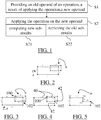
- the method comprises providing (S1) an old operand of an operation, a result of applying the operation to the old operand, wherein applying the operation to the old operand includes computing old sub-results, each old sub-result being determined by a respective old sub-operand of the old operand, and a new operand including a first set of sub-operands of the new operand at least partially identical to old sub-operands of the old operand, and a second set of new sub-operands.
- the method further comprises applying (S2) the operation on the new operand.
- Applying the operation on the new operand includes computing (S21) new sub-results determined by a respective sub-operand of the second set; and retrieving (S22) the old sub-results determined by the old sub-operands of the old operand to which sub-operands of the first set are at least partially identical.
- Such a method improves the update of the modeled object.
- a modeled object is an object modeled by data allowing a computer manipulation of the object. By extension, it designates the data itself.
- the method is intended for updating any type of modeled object, as long as the modeled object is obtained by applying at least one operation on an operand. Thus, in the method, all modeled objects are obtained by applying operations.
- the data modeling the modeled object may thus include data allowing the retrieval of elements of the operation.
- the providing (S1) of an old operand of the operation, a result of applying the operation to the old operand, wherein applying the operation to the old operand includes computing old sub-results, each old sub-result being determined by a respective old sub-operand of the old operand may comprise retrieving all these elements.
- the old operand, the old sub-operands and/or the old sub-results may be retrieved from the data modeling the object.
- all these elements may be referenced and pointers may lead to them.
- the object is 3D modeled object, representing a thin casted part.
- 3D modeled object it is meant any object which is modeled by data allowing its 3D representation.
- a 3D representation allows the viewing of the part from all angles.
- a 3D modeled object when 3D represented, may be handled and turned around any of its axes, or around any axis in the screen on which the representation is displayed. This notably excludes 2D icons, which are not 3D modeled.
- the display of a 3D representation facilitates design (i.e. increases the speed at which designers statistically accomplish their task). This speeds up the manufacturing process in the industry, as the design of the products is part of the manufacturing process.
- the following examples concern a modeled object which is a 3D modeled object defined in a CAD system.
- the modeled object is (or is derived from) the result of applying the operation to an operand.
- the operand is any input of the operation.
- Applying the operation to the old operand includes computing old sub-results, each old sub-result being determined by a respective old sub-operand of the old operand.
- a sub-operand designates sub-data of the operand.
- the operand is the set of its sub-operands or an assembly of these sub-operands.
- the sub-operands may be directly stored in the data modeling the object or may be deduced from such data.
- the old sub-results may also be stored or deductible.
- a sub-result is determined by a respective sub-operand. This means that a sub-operand fully determines a sub-result, independently of the other sub-operands.
- the method is intended for updating a modeled object.
- the method provides (S1) a new operand.
- the new operand is merely an operand of the operation, just like the old operand. However, the new operand is to take the place of the old operand.
- the new operand derives from a modification upon user action.
- the new operand may be the result of a previous operation of which operand has been modified.
- history based CAD systems store the whole history of a 3D modeled object as a tree, wherein the leaf nodes are solids and the other nodes are operations.
- a modification of a user is for these systems typically to change leaf solids of a node operation, the modification being reflected through the whole history, each operation possibly seeing its operand modified as a result.
- the method is typically iterated over the operations of the history, the new result of the previous operation being the new operand of the next operation.
- the new operand includes a first set of sub-operands of the new operand at least partially identical to old sub-operands of the old operand, and a second set of new sub-operands.
- the sub-operands of the new operand may be classified in two categories: the ones which are similar (i.e. at least partially identical, e.g. sharing common values for at least some of their parameters) to sub-operands of the old operand (the first set) and the other ones (the second set).
- two sub-operands are partially identical if their respective sub-results are identical or sets of non empty intersection.
- modifying the modeled object may comprise modifying the old operand (into the new operand), which in turn may comprise modifying the sub-operands of the old operand.
- Sub-operands may be deleted, some sub-operands may be modified, and new sub-operands may be added. The method keeps track of this by classifying the sub-operands of the new operand in the two sets.
- the method further comprises applying (S2) the operation on the new operand.
- updating the modeled object once the new operand is provided comprises determining the new result of the operation with this new operand. This is performed by applying the operation on the new operand.
- Applying the operation on the new operand includes computing (S21) new sub-results determined by a respective sub-operand of the second set. Indeed, the sub-operands of the second set are totally new and sub-results determined by them have to be computed.
- Computing a sub-result means evaluating how the operation acts on the respective sub-operand. This depends on the operation and on the context of the method. Computing a sub-result may include non-logical operations.
- Applying the operation on the new operand however also includes retrieving (S22) the old sub-results determined by the old sub-operands of the old operand to which sub-operands of the first set are at least partially identical.
- Retrieving the old sub-results means that the method does not evaluate how the operation acts on the sub-operand (as opposed to the computing). Thus, retrieving a sub-result is faster than computing a sub-result.
- the method classifies the sub-operands in two sets in order to retrieve for some of the sub-operands respective sub-results from previous computations (i.e. the old sub-results determined by the old sub-operands to which the sub-operands of the first set are partially identical).
- the classification and the retrieving of old sub-results may include essentially logical operations and are thus performed very fast.
- the computing of sub-results is kept to the strict minimum.
- the method allows a fast update of a modified modeled object.
- the operation includes computing the intersections between the faces of two solids.
- the operation includes offsetting a solid.
- the operation includes computing the intersections between the faces of two solids.
- the old sub-operands and the sub-operands of the new operand each comprise a couple of faces.
- a couple of faces includes two faces which are ordered and are designated as a "first" face and a "second" face according to their order in the couple.
- the old sub-results and the new sub-results comprise intersections between the first face and the second face of the respective sub-operand.
- a sub-operand is a couple of a first face and second face
- the sub-result determined by the respective sub-operand is the intersection(s) between the first face and the second face.
- the respective sub-result may also be the set of all intersections of the support planes of the faces.
- Such a method allows a fast update of intersections between two solids bounded by faces.
- the faces of the first solid may form the first faces of the sub-operands while the faces of the second sold may form the second faces.
- couples comprising all combinations of two faces from the first and second solid, all intersections may thus be obtained.
- Such a method is particularly useful in the case the operation is a Boolean operation between the first solid bounded by first faces and the second solid bounded by second faces. Indeed, sub-results of the result of a Boolean operation include the intersections between the two solids.
- a basic of 3D modeling algorithms is to compute a new solid from two input solids according to a design operation.
- Design operations are typically "union”, “intersection” and “subtraction” and are often named “Boolean operations”. It must however be noted that trimming, splitting, rounding and filleting are also design operations that can take benefit of the method. Nevertheless, the method is first illustrated in the context of Boolean operations.
- Input and resulting solids may be modeled by their boundary representation (B-Rep).
- the boundary representation captures topological adjacency as well as geometrical definition.
- Topological objects are called cells, which is a generic name for volume, face, edge and vertex. Cells are pure logical entities.
- Geometrical objects are planes, surfaces (NURBS, B-spline, Bezier), curves (line, NURBS, B-spline, Bezier), p-curves (explained below) and points, they are numerical entities (mathematical real numbers or computer floating point numbers). All geometrical objects may be subsets of the 3D space.
- Topological structure may capture that the volume is bounded by faces, a face is bounded by edges and an edge is bounded by vertices. A face is the restriction of a plane or a surface. An edge is the restriction of a curve.
- the geometrical description of the edge may include a 3D curve and a p-curve ("parametric-curve").
- intersection curve of surfaces S 1 and S 2 may be for the surface/surface intersection algorithm to provide two p-curves and a 3D curve as previously defined. Consequently, once computed and stored in the B-rep data structure, the intersection curve of two faces may be easily accessed by visiting the topological and geometrical data structure.
- typical solid modeling algorithm may include the following steps:
- First step performs geometrical operations, mainly surface-surface intersections, and is known to be the most computer time consuming.
- the update method proposed speeds up this step by retrieving some of the surface-surface intersections previously computed and thus avoid to compute these intersections again.
- Second and third steps do not involve so many geometrical computations and are mainly concerned by rearranging topology, which is a logical structure.
- the topological and geometrical data structure allows reading intersection curves (3D curve and p-curves) on the resulting solid.
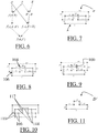
- Input solids are two parallelepipeds A and B shown on FIG. 2 and represented as rectangles on the figures (for this representation reason, parallelepipeds may be referred to as "rectangles" in the following). Faces of the solids (represented as edges on the figures) are referenced by numbers. In this example, operation A - B is foreseen.
- the first step is to compute two intersection curves (represented as emphasized vertices on the figures), as illustrated on FIG. 3 .
- One curve 100 between face 4 and face 5 and another curve 102 between faces 3 and face 6 are obtained, as illustrated on FIG. 4 .
- the sub-operands are the couples taken singly. In fact, most sub-operand result in a null sub-result (there is no intersection). Only couples (4, 5) and (3, 6) lead to a non null result.
- the second step is to split faces according to intersection curves. Face 4 is split into two adjacent faces 40, as well as face 3 which is split into two adjacent faces 42, as illustrated on FIG. 4 .
- Third step represented on FIG. 5 is to select faces 1,2,9,10,11,12 as the resulting faces, according to the type of the operation: large rectangle A minus small rectangle B in this case.
- these two last steps, known per se, are not of directly concern to the method.
- a and B be the input lists of faces and f ( A , B ) the resulting list of intersection curves obtained through faces of A against faces of B. Notice that the list of all sub-results f ( A,B ) is not the final solid, but it is an intermediate result (this is why the elements of this list are referred to as "sub"-results).
- the algorithm is described in the simple case where previous solid A is unchanged. The case when both input solids are changed is illustrated later.
- B' be a modified version of B.
- the notation B ( B - B' )+( B ⁇ B' ) highlights the list of faces B ⁇ B' of B shared with B' and the list of faces B-B' of B that are not in B' .
- the method allows to provide the new result f ( A,B' ) by retrieving f ( A,B ⁇ B' ) from the previous result, and thus not re-computing intersection curves f ( A,B ⁇ B' ), and by only computing the actually new curves f ( A,B' - B ).
- Second and last step is to retrieve previous results as much as possible.
- This step is the implementation of term f ( A,B ⁇ B' ) in the algebraic formula.
- This step makes use of the relationship j linking faces of the previous input solids A, B to their children split faces in the previous resulting solid D .
- This step makes use of the previous resulting solid data structure D by reading intersection curves of adjacent faces.
- Operator ⁇ returns the list of boundary edges of a face. Given faces a ⁇ A and b ⁇ B ⁇ B', the condition ⁇ j ( a ) ⁇ ⁇ j ( b ) ⁇ checks if there exists any intersection between faces a and b within the previous result. This test is performed by logical comparison of edges lists.
- Faces of the new operand may be linked to faces of the old operand. This linking may be performed through pointers or conservation of identifiers. The linking allows a faster retrieving (S22) of the old sub-results.
- faces of the new operand may be linked to faces of the old operand according to the modification.
- faces of the old operand which are not geometrically modified may be linked to their corresponding face in the new operand.
- the example is to update the new solid after the small rectangle B of FIGS. 2-5 is changed into the inverted U-shape B' , as illustrated by faces 5, 6, 13, 14, 15, 16 and 17 in FIG. 7 .
- Dotted lines are the new faces of new input solid B'.
- New sub-operands are thus couples involving these new faces.
- Face numbering captures that face 5 and face 6 of the initial rectangle B are the same in the new version B' of B . In implementations, they may be linked to the corresponding faces in the initial rectangle B as discussed earlier, or identifiers may be kept. Large rectangle A is unchanged.
- the second step may also replace faces 3 and 6 by the adjacent faces 9 and 10 from the previous resulting solid D .
- the second step may finally replace face 5 by face 11 from the previous resulting solid D . This yields the result on FIG. 9 .
- next step may be to split face 4 into three adjacent faces 144, to split face 17 into two adjacent faces 117, to split face 1 into two adjacent faces 111 and to split face 16 into two adjacent faces 166, as illustrated on FIG. 10 .
- the very last step typically provides the resulting solid D' by selecting faces according to the type of the operation, as illustrated on FIG. 11 . Notice that face 2 is shared with first input solid A and faces 9, 10 and 11 are reused from previous resulting solid D .
- Boolean case Another example of the Boolean case is now formally described with reference to FIG. 12 .
- the principle is to compute f ( A',B' ) by retrieving f ( A ⁇ A',B ⁇ B' ) directly from the previous result, and thus avoiding computation.
- the algorithm may involve in this example four loops instead of two loops.
- First loop is to compute intersections curves between new faces A'-A and new faces B'-B. All these are new intersection curves that have to be computed anyway. This is described by the following pseudo-code:
- Third loop is to compute intersection curves between new faces B'-B and faces A ⁇ A' shared with previous input A .
- Last loop is to retrieve as much as possible intersection curves and faces available from previous result. This loop makes use of flags computed by second and third loops. Thanks to these flags, we know whether a face of A ⁇ A' or B ⁇ B' is involved in some intersection curve operation. Flagged faces are potentially modified by the operation and they cannot be replaced by their previous resulting faces. This is described by the following pseudo-code:
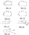
- FIGS. 13-16 The initial union operation between input solids of the example is illustrated on FIGS. 13-16.
- FIG. 17 illustrates the new versions of input solids. Notice that they are both modified. Dotted lines illustrate new faces.
- the first loop computes all new intersection curves, as illustrated on FIG. 18 .
- Second and third loops retrieve intersection curves (small circles) and perform some face replacements as illustrated on FIG. 19 .
- Second and third loops perform as well some face replacements, as illustrated on FIG. 20 .
- the (traditional) end of the algorithm splits faces according to intersection curves and selects faces that belong to the resulting solid, as illustrated on FIGS. 21-22 .
- the first face and the second face each share a common surface with the first face and the second face of the partially identical old sub-operand.
- this partial identity was a full identity.
- the sub-operands of the first set of sub-operands of the new operand are identical to the corresponding sub-operands of the old operand.
- faces of the old operand may be reduced or increased.
- the corresponding faces of the new operand may then be linked to the face they are the reduction/increase of, in addition to faces which are not modified.
- the idea is to retrieve intersections of couples of faces which include at least one face which has been modified, but in a way that intersection curves may be conserved.
- the concept of "sharing a common surface" for two faces covers the case where the faces are the same, as well as the case where one of the two surfaces is a reduction of the other (the other being an increase of the former). This allows an optimal retrieve of reusable intersections.
- faces of the old operand (operands being seen here as the list of couples of faces of two solids) which are not modified, as well as faces which are increased of reduced may all be linked to the faces of the new operand to which they correspond. This may be done by conservation of identifiers, by pointers, and/or by a common sub-identifier.
- the method may then further comprise determining the first set as all the sub-operands of the new operand of which the first face and the second face are both linked to faces of the old operand.
- intersection curves are retrieved by using faces that are shared by previous and new input solids.
- this method can ignore some intersection curves in the following case: new input solid features a new face that is the restriction of a plane or surface shared by a face of the previous input solid. It happens for example when the boundary of a face is modified, but not its support plane or surface. Since intersection curves may be computed from geometrical supports (planes or surfaces) they can be retrieved as well in this case, as explained in the following.
- a difficulty is that the B-Rep data structure saves the link from the topological cell (the face) toward its geometrical support (the plane or surface).
- This pointer (from the topological object toward the geometrical object) is designed to facilitate all basic computations: intersection, tessellation, set membership classification, etc.
- a problem in the context of the method is that the reverse pointer may be useful: from the plane or surface toward the face. Thanks to standard data processing tools (sorting, hash table etc.) a preprocessing step may compute the reverse pointer, and the following algorithm can be implemented.
- Notation s S x ( x ) symbolizes the direct pointer, meaning that s is the support plane or surface of face x in solid X .
- the example is to update the new solid after the small rectangle B is changed into a longer rectangle B' , as illustrated by faces 7, 30, 31 and 32 in FIG. 23 .
- Dotted lines are the new faces of input solid B .
- Face numbering captures that face 7 of the initial rectangle B is the same in the new version B' of B.
- the first step computes the genuinely new intersection curve 240 between face 4 and face 30 (small cross in FIG. 24 ). Furthermore, it retrieves from previous resulting solid the intersection curve 242 between the supporting plane of face 31 and the supporting plane of face 3 (small circle in FIG. 24 ). This is possible because the supporting plane of face 31 is the same as the supporting plane of face 6. Furthermore, face 3 of first input solid A is replaced by face 9 of previous resulting solid D .
- Next step is to yield the new resulting solid through usual algorithm, which results in solid D' of FIG. 25 .
- the method has been described above for an operation which is a Boolean operation. However, the method is also applicable to other operations such as filleting or rounding.
- the sub-operands are couples of faces meeting at an edge or lists of faces meeting at a vertex.
- the operation consists in trimming the sub-operand faces and constructing new round surfaces to fill the hole left by the trimming. Foreseen sub-results may thus be the trimming curves and the constructed surfaces for example.
- the operation may be any CAD solid operation.
- the operations comprise at least one solid shell operation, wherein the shell operation involves one or two solid offset operations.
- at least a part of the old sub-operands and the sub-operands of the new operand each comprise a face.
- the old sub-results and the new sub-results, determined by a respective sub-operand of the part, each comprise an offset face of the face of the respective sub-operand.
- the methods is here particularly advantageous because the offset and shell operations are time consuming as they duplicate most faces of the solid.
- solid offset and solid shell operations are very popular in mechanical design for thin casted parts such as plastic parts or aluminum parts.
- At least another part of the old sub-operands and the sub-operands of the new operand each comprise a couple of offset faces
- the old sub-results and the new sub-results determined by a respective couple of offset faces comprise an intersection curve between the respective couple of offset faces.
- an offset operation consists in duplicating faces (into offset faces), computing the intersections of couples of offset faces, and finally trimming them.
- the resulting offset solid may be defined by locally increasing or decreasing the dimension of the solid according to the offset values, as illustrated on FIGS. 26-27 which show an example of solid A reduced to solid B by an offset operation.
- a positive offset value adds material to the solid and a negative offset values (locally) removes material from the solid.
- a face associated with an offset value "zero" remains untouched (lower face 260 of the L-shape solid in FIGS. 26-27 ).
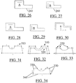
- FIGS. 28-30 An example of a shell operation is now discussed with reference to FIGS. 28-30 .
- the solid shell operation is to be computed on both sides of the initial solid, then two offset values are associated to each face.
- the method may create two solid offsets and perform the operation "large solid offset minus small solid offset", which yields the resulting thin solid iC.
- the bottom line is that the solid shell operation involves one or two solid offset operations together with one Boolean operation (subtraction). Consequently, only the method for accelerating the solid offset operation is exemplified in the following.
- the solid shell operation inherits performance from both the solid offset operation and the Boolean operation (described previously).
- the traditional solid offset algorithm mainly runs four steps.
- the first step is to compute offset faces of all faces of the input solid.
- the main task here in terms of computer time, is offset computation of support planes and surfaces. These offset faces are computed independently, so they locally overlap (as illustrated on FIG. 32 which represents offset faces 320 of faces of solid 310 of FIG. 31 ) or they are locally separated.
- the second step is to extrapolate faces that are separated in such a way that they intersect (not illustrated).
- the third step is to compute intersection curves 330 between couples of overlapping faces (illustrated on FIG. 33 ).
- the fourth and last step is to mutually trim these offset (and extrapolated) faces in order to provide the closed boundary 340 of the resulting solid offset.
- the link between input faces and resulting faces captures the offset relationship, as illustrated on FIG. 34 .
- the input solid may be changed according to FIG. 35 .
- the right hand side features a protrusion 350 (faces 13, 14 and 15) while left and top sides are unchanged (faces 2, 3, 4 and 5).
- Dotted lines represent new faces.
- Solid lines represent unchanged faces.
- A be the set of faces of the previous input solid
- A' be the set of faces of the new input solid.
- A'-A and A' ⁇ A respectively the set of new faces of the new input solid and the set of faces of the new input solid shared with the previous input solid and associated with the same offset values.
- a face of the new input solid that is shared with the previous input solid and that is associated with a different offset value is considered as a new input face.
- B be the previous offset solid.
- the method may start by computing offset faces of all new input faces, as illustrated in the following pseudo-code:
- Off ( X ) the set of offset faces of the set of faces X. Elements of Off ( X ) are noted Off ( x ) meaning that Off ( x ) is the offset face of x. Solid lines are offset faces of unchanged faces Off ( A' ⁇ A ) and dotted lines are offset faces of new faces Off ( A' - A ).
- offset faces 380 are extrapolated when needed (as illustrated on FIG. 38 ).
- the intersection curves computation may include three sub-steps.
- the first sub-step computes intersection curves between offset surfaces of new faces. This is illustrated in the following pseudo-code:
- intersections curves computed by the above loop are represented as crosses on FIG. 39 .
- FIG. 40 Small circles on FIG. 40 represent intersection curves with previous resulting offset surfaces. It should be noticed that the support surface of the new face 16 is the same as the one of the previous face 1, so the intersection curve 200 between face 16 with the offset face Off (2) is retrieved from previous result. Intersection curve 201 is retrieved from previous result as well because new face 13 is a topological restriction of the support surface of previous face 6 and because face 5 is reused in the new input solid. Finally, offset faces Off (3) and Off (4) are flagged "0" while offset faces Off (2) and Off (5) are flagged "1".
- Last sub-step retrieves topological trimming from previous result.
- Flowchart of FIG. 43 represents an example of the method in such a context.
- a previous operation is performed, and previous input objects as well as previous output object are saved in the database. Then the user modifies input objects by providing new versions of said input objects and asks the CAD system to update the output object.
- the method avoids avoidable computation by directly retrieving partial results from the previous output object. Depending on the operation type, these partial results are intersection curves, face-face trimming, round and fillet ribbon faces, or any geometrical or topological result.
- the method deals with solid objects and surface objects modeled by their boundary representation (B-Rep). All traditional 3D modeling operations can take benefit of the invention: solid modeling Boolean operations (union, intersection, subtraction), rounding and filleting, surface cut etc.
- the method avoids computation, which accelerates the updating process. This is particularly efficient for two reasons. Firstly, geometrical computations are saved, which are known to be the most computer time consuming. Secondly, while designing a virtual 3D object, the user spends 80% of time changing and updating a previous version of the design, which is precisely where the method is efficient. Furthermore, reusing existing data saves computing memory as well as database memory by avoiding data duplication. Finally, the method makes use of data that are usually saved by current history based CAD systems, namely previous input objects and previous output objects. This makes the method easily implementable within current CAD systems.
- the method is typically run with a computer-aided design system, adapted for performing the method, and comprising a graphical user interface and a database suitable for storing the old sub-results.
- a computer-aided design system adapted for performing the method, and comprising a graphical user interface and a database suitable for storing the old sub-results.
- Such a system allows faster CAD. Indeed, in most cases of update, such a system will run the method and thus save time.
- a computer program may comprise instructions for execution by a computer, the instructions comprising means for performing the method with the graphical user interface of the computer-aided design system.
- a computer readable storage medium may have recorded thereon the computer program.
- the above method is computer-implemented, which means that the steps of the method are executed by a computer.
- the triggering of at least some of the steps of the method may be performed through user-computer interaction.
- the level of user-computer interaction required may depend on the level of automatism foreseen and put in balance with the need to implement the user's desideratum. In embodiments, this level may be user-defined and/or pre-defined.
- the providing of the new operand is performed by a user while other actions of the method are performed by the computer.
- the invention is also directed to a CAD system adapted for performing the method.
- a user is provided with a graphical user interface (or GUI) such as the one of CATIA, the GUI being in relation with a means, e.g. a database, for storing data necessary to the execution of the method.
- GUI graphical user interface
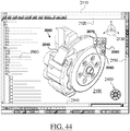
- the exemplified graphical user interface (or GUI) 2100 may be a typical CAD-like interface, having standard menu bars 2110, 2120, as well as bottom and side toolbars 2140, 2150.
- Such menu- and toolbars contain a set of user-selectable icons, each icon being associated with one or more operations or functions, as known in the art.
- the software tools may be grouped into workbenches.
- Each workbench comprises a subset of software tools.
- one of the workbenches is an edition workbench, suitable for editing geometrical features of the modeled product 2000.
- a designer may for example pre-select a part of the object 2000 and then initiate an operation (e.g. change the dimension, color, etc.) or edit geometrical constraints by selecting an appropriate icon.
- typical CAD operations are the modeling of the punching or the folding of a 3D modeled object displayed on the screen.
- the GUI may for example display data 2500 related to the displayed product 2000.
- the data 2500, displayed as a "feature tree", and their 3D representation 2000 pertain to a brake assembly including brake caliper and disc.
- the GUI may further show various types of graphic tools 2130, 2070, 2080 for example for facilitating 3D orientation of the object, for triggering a simulation of an operation of an edited product or render various attributes of the displayed product 2000.
- a cursor 2060 may be controlled by a haptic device to allow the user to interact with the graphic tools.
- the part 2000 can be any object in any configuration capable of being defined by a CAD/CAM/CAE system, or any system used to display views of an object from varying viewpoints.
- the invention may thus be implemented on a computer program comprising instructions by a computer, the instructions comprising means for causing the above system to perform the above method.
- the invention may for example be implemented in digital electronic circuitry, or in computer hardware, firmware, software, or in combinations of them.
- Apparatus of the invention may be implemented in a computer program product tangibly embodied in a machine-readable storage device for execution by a programmable processor; and method steps of the invention may be performed by a programmable processor executing a program of instructions to perform functions of the invention by operating on input data and generating output.
- the invention may advantageously be implemented in one or more computer programs that are executable on a programmable system including at least one programmable processor coupled to receive data and instructions from, and to transmit data and instructions to, a data storage system, at least one input device, and at least one output device.
- the application program may be implemented in a high-level procedural or object-oriented programming language, or in assembly or machine language if desired; and in any case, the language may be a compiled or interpreted language.
- FIG. 45 shows a client computer system, e.g. a workstation of a user.
- the client computer comprises a central processing unit (CPU) 1010 connected to an internal communication BUS 1000, a random access memory (RAM) 1070 also connected to the BUS.
- the client computer is further provided with a graphical processing unit (GPU) 1110 which is associated with a video random access memory 1100 connected to the BUS.
- Video RAM 1100 is also known in the art as frame buffer.
- a mass storage device controller 1020 manages accesses to a mass memory device, such as hard drive 1030.
- Mass memory devices suitable for tangibly embodying computer program instructions and data include all forms of nonvolatile memory, including by way of example semiconductor memory devices, such as EPROM, EEPROM, and flash memory devices; magnetic disks such as internal hard disks and removable disks; magneto-optical disks; and CD-ROM disks 1040. Any of the foregoing may be supplemented by, or incorporated in, specially designed ASICs (application-specific integrated circuits).
- a network adapter 1050 manages accesses to a network 1060.
- the client computer may also include a haptic device 1090 such as cursor control device, a keyboard or the like.
- a cursor control device is used in the client computer to permit the user to selectively position a cursor at any desired location on display 1080, as mentioned with reference to FIG. 44 .
- the cursor control device allows the user to select various commands, and input control signals.
- the cursor control device includes a number of signal generation devices for input control signals to system.
- a cursor control device may be a mouse, the button of the mouse being used to generate the signals.
Claims (4)
- Rechnergestütztes Verfahren zum Konstruieren eines dreidimensionalen modellierten Objektes, das ein herzustellendes dünnes Gussteil darstellt, wobei das Verfahren umfasst:mit einem verlaufsgestützten CAD-System, umfassend eine graphische Benutzeroberfläche, die eine Tesselierung einer Grenzdarstellung des dreidimensionalen modellierten Objektes anzeigt:- Schaffen eines Verlaufs CAD-Festkörperoperationen bei einem Eingreifen eines Benutzers, wobei der Verlauf als Baumstruktur gespeichert wird, wobei die Blattknoten der Baumstruktur jeweils eine von einer Grenzdarstellung modellierte Festkörperdarstellen und die anderen Knoten der Baumstruktur jeweils eine Operation darstellen, wobei die im Verlauf definierten Berechnungen zur Grenzdarstellung des dreidimensionalen modellierten Objektes führen, wobei:• jede Operation als Eingabe einen alten Operanden nimmt, der mindestens eine eingegebene Festkörper umfasst, und eine ausgegebene Festkörper ausgibt, die aus der Anwendung der Operation auf den alten Operanden resultiert, wobei die mindestens eine eingegebene Festkörper und die ausgegebene Festkörper jeweils von einer Grenzdarstellung modelliert werden;• das Anwenden jeder Operation auf deren alten Operanden Berechnen alter Unterergebnisse umfasst, wobei jedes alte Unterergebnis durch einen jeweiligen alten Suboperanden des alten Operanden bestimmt wird; und• die Operationen mindestens eine Festkörper-Hülle-Operation umfassen, wobei die Hülle-Operation eine oder zwei Festkörperversatzoperationen und eine Boolesche Operation, die eine Subtraktion ist, beinhaltet, und wobei für die Boolesche Operation:▪ die mindestens eine eingegebene Festkörper eine erste eingegebene Festkörper (A) und eine zweite eingegebene Festkörper (B) umfasst,▪ die Grenzdarstellung der ersten eingegebenen Festkörper durch erste Stirnflächen abgegrenzt ist,▪ die Grenzdarstellung der zweiten eingegebenen Festkörper durch zweite Stirnflächen abgegrenzt ist, und▪ das Anwenden der Booleschen Operation Berechnen der Schnittpunkte zwischen den ersten Stirnflächen und den zweiten Stirnflächen beinhaltet;- Speichern des Verlaufs und der Grenzdarstellung; undmit einem verlaufsgestützten CAD-System, umfassend eine graphische Benutzeroberfläche, die eine Tesselierung einer Grenzdarstellung des dreidimensionalen modellierten Objektes anzeigt:- Modifizieren mindestens eines Blattknotens der Baumstruktur bei einem Eingreifen eines Benutzers;- automatisches Aktualisieren der Grenzdarstellung des dreidimensionalen modellierten Objektes, wobei:• das Aktualisieren Spiegeln der Modifikation des mindestens einen Blattknotens durch den ganzen Verlauf hindurch beinhaltet,• das Spiegeln eine Iteration der Operationen des Verlaufs umfasst,• die Iteration für jede Operation, für die der alte Operand zu einem neuen Operanden modifiziert wird, umfasst:▪ Vorsehen:∘ des alten Operanden der Operation,∘ der ausgegebenen Festkörper der Operation, und∘ des neuen Operanden, wobei der neue Operand eine erste Menge Suboperanden des neuen Operanden, die mindestens teilweise identisch sind mit alten Suboperanden des alten Operanden, und eine zweite Menge neuer Suboperanden umfasst,▪ Anwenden (S2) der Operation auf den neuen Operanden, umfassend:∘ Berechnen (S21) neuer Unterergebnisse, die durch einen jeweiligen Suboperanden der zweiten Menge bestimmt werden; und∘ Abrufen (S22) der alten Unterergebnisse, die durch die alten Suboperanden des alten Operanden bestimmt werden, mit dem Suboperanden der ersten Menge mindestens teilweise identisch sind; und• für jede Boolesche Operation jeder Hülle-Operation, für die der alte Operand zu einem neuen Operanden ((A,B')) modifiziert wird :▪ der alte Operand die Menge aller Stirnflächenpaare ({(i, j)i=i...4, j=5...8}) der Grenzdarstellungen, die die erste Festkörper (A) und die zweite Festkörper (B) modellieren, wobei ein Paar ein geordnetes Paar ist und jedes Stirnflächenpaar eine erste Stirnfläche und eine zweite Stirnfläche umfasst;▪ die alten Suboperanden jeweils ein jeweiliges Paar des alten Operanden sind;▪ die alten Unterergebnisse, die durch einen jeweiligen alten Suboperanden bestimmt werden, Schnittpunkte sind zwischen der ersten Stirnfläche und der zweiten Stirnfläche des jeweiligen Suboperanden, wobei die Schnittpunkte parametrische Kurven der Grenzdarstellungen sind, die das Ergebnis der Anwendung der Booleschen Operation auf den alten Operanden modellieren;▪ zwei Suboperanden teilweise identisch sind, wenn ihre jeweiligen Unterergebnisse identisch oder Mengen mit nicht leeren Schnittpunkten sind;▪ die erste Stirnfläche und die zweite Stirnfläche für jedes Stirnflächenpaar der Suboperanden der ersten Menge sich jeweils eine gemeinsame Oberfläche mit der ersten Stirnfläche und der zweiten Stirnfläche des teilweise identischen alten Suboperanden teilen;▪ die neuen Suboperanden jeweils ein jeweiliges Paar des neuen Operanden sind;▪ Stirnflächen des neuen Operanden mit Stirnflächen des alten Operanden verknüpft sind, wobei eine Stirnfläche eines Operanden eine erste Stirnfläche oder eine zweite Stirnfläche eines Suboperanden des Operanden ist;▪ Stirnflächen des neuen Operanden gemäß der Modifikation des alten Operanden mit Stirnflächen des alten Operanden verknüpft sind, wobei nicht geometrisch modifizierte Stirnflächen des alten Operanden mit ihrer entsprechenden Stirnfläche im neuen Operanden verknüpft sind und verkleinerte oder vergrößerte Stirnflächen des alten Operanden mit ihrer entsprechenden Stirnfläche beim neuen Operanden verknüpft sind; und▪ Anwenden (S2) der Operation auf den neuen Operanden umfasst:∘ Bestimmen der ersten Menge als alle Suboperanden des neuen Operanden, dessen erste Stirnfläche und zweite Stirnfläche beide mit Stirnflächen des alten Operanden verknüpft sind;∘ Berechnen (S21) neuer Unterergebnisse (104, 106), die durch einen jeweiligen Suboperanden der zweiten Menge bestimmt werden; wobei:✔ die neuen Unterergebnisse Schnittpunkte zwischen der ersten Stirnfläche und der zweiten Stirnfläche des jeweiligen Suboperanden sind, wobei die Schnittpunkte parametrische Kurven der Grenzdarstellungen sind, die das Ergebnis der Anwendung der Operation auf den neuen Operanden modellieren, und✔ das Ergebnis der Anwendung der Operation auf den neuen Operanden als Grenzdarstellung bereitgestellt wird; und∘ Abrufen (S22) der durch die alten Suboperanden des alten Operanden, mit dem Suboperanden der ersten Menge mindestens teilweise identisch sind, bestimmten alten Unterergebnisse (100, 102), wobei das Abrufen (S22) umfasst: Zugreifen auf parametrische Kurven, die Stimflächenpaaren des alten Operanden, die mit Stimflächenpaaren der ersten Menge entsprechen, in der Grenzdarstellung, die das Ergebnis der Anwendung der Operation auf den alten Operanden modelliert.
- CAD-System, das zur Ausführung des Verfahrens nach Anspruch 1 geeignet ist, und umfasst:a) eine graphische Benutzeroberfläche,b) eine Datenbank, die zum Speichern der alten Unterergebnisse geeignet ist.
- Computerprogramm, umfassend Befehle zur Ausführung durch einen Computer, wobei die Befehle Mittel zur Ausführung des Verfahrens nach Anspruch 1 mit einer graphischen Benutzeroberfläche eines CAD-Systems umfassen, wobei das System ferner eine Datenbank umfasst, die zum Speichern der alten Unterergebnisse geeignet ist.
- Computerlesbarer Datenträger, auf dem ein Computerprogramm nach Anspruch 3 gespeichert ist.
Priority Applications (2)
| Application Number | Priority Date | Filing Date | Title |
|---|---|---|---|
| EP10306544.7A EP2474930B1 (de) | 2010-12-30 | 2010-12-30 | Aktualisierung eines modellierten Objekts |
| US13/325,875 US8983804B2 (en) | 2010-12-30 | 2011-12-14 | Updating a modeled object |
Applications Claiming Priority (1)
| Application Number | Priority Date | Filing Date | Title |
|---|---|---|---|
| EP10306544.7A EP2474930B1 (de) | 2010-12-30 | 2010-12-30 | Aktualisierung eines modellierten Objekts |
Publications (2)
| Publication Number | Publication Date |
|---|---|
| EP2474930A1 EP2474930A1 (de) | 2012-07-11 |
| EP2474930B1 true EP2474930B1 (de) | 2018-10-24 |
Family
ID=44140935
Family Applications (1)
| Application Number | Title | Priority Date | Filing Date |
|---|---|---|---|
| EP10306544.7A Active EP2474930B1 (de) | 2010-12-30 | 2010-12-30 | Aktualisierung eines modellierten Objekts |
Country Status (2)
| Country | Link |
|---|---|
| US (1) | US8983804B2 (de) |
| EP (1) | EP2474930B1 (de) |
Families Citing this family (10)
| Publication number | Priority date | Publication date | Assignee | Title |
|---|---|---|---|---|
| EP2474928A1 (de) | 2010-12-30 | 2012-07-11 | Dassault Systèmes | Vereinigen modellierter Objekte |
| EP2474929A1 (de) * | 2010-12-30 | 2012-07-11 | Dassault Systèmes | Aktualisierung modellierter Objekte |
| US10311169B1 (en) * | 2012-11-09 | 2019-06-04 | Msc.Software Corporation | Interactive edge manipulation systems and methods |
| US9569564B2 (en) * | 2013-02-11 | 2017-02-14 | Ford Global Technologies, Llc | Automated cad process for creating mold packages |
| EP2849099B1 (de) | 2013-09-11 | 2021-07-28 | Dassault Systèmes | Computerimplementiertes Verfahren zum Entwurf eines mit einem binären Baum modellierten Industrieprodukts |
| US10074218B1 (en) * | 2013-12-23 | 2018-09-11 | Dassault Systemes Solidworks Corporation | 3D content creation tool with automatic mating |
| US10325052B1 (en) * | 2016-09-15 | 2019-06-18 | Cadence Design Systems, Inc. | Method and system for implementing custom inter-layer transitions for a multi-layer bus |
| KR20180051288A (ko) * | 2016-11-08 | 2018-05-16 | 삼성전자주식회사 | 디스플레이 장치 및 그 제어 방법 |
| US10628997B2 (en) * | 2017-08-24 | 2020-04-21 | Emilio Santos | Method for generating three-dimensional models from constrained sketches and an instruction set |
| CN112100056A (zh) * | 2020-08-14 | 2020-12-18 | 珠海金智维信息科技有限公司 | 应用评估方法、系统、装置、设备及介质 |
Family Cites Families (18)
| Publication number | Priority date | Publication date | Assignee | Title |
|---|---|---|---|---|
| US5850535A (en) | 1995-10-12 | 1998-12-15 | Computervision Corporation | Roll-back during regeneration on a computer-aided design system |
| US7079114B1 (en) * | 1998-08-21 | 2006-07-18 | Peter Smith | Interactive methods for design of automobiles |
| US6341291B1 (en) | 1998-09-28 | 2002-01-22 | Bentley Systems, Inc. | System for collaborative engineering using component and file-oriented tools |
| US7313504B2 (en) * | 2001-10-15 | 2007-12-25 | Solidworks Corporation | Model management technology using grouping of features |
| US8429174B2 (en) * | 2003-01-25 | 2013-04-23 | Purdue Research Foundation | Methods, systems, and data structures for performing searches on three dimensional objects |
| EP1501026A1 (de) | 2003-07-25 | 2005-01-26 | Dassault Systèmes | CAD System mit einer kontextfreien Grammatik |
| US7913190B2 (en) * | 2005-07-18 | 2011-03-22 | Dassault Systèmes | Method, system and software for visualizing 3D models |
| US7755621B2 (en) | 2006-06-16 | 2010-07-13 | Autodesk, Inc. | Fast interactive object manipulation |
| US20080140732A1 (en) | 2006-12-11 | 2008-06-12 | Bentley System, Inc. | Method and system for sharing file based data |
| US8305376B2 (en) | 2007-04-12 | 2012-11-06 | Dassault Systemes Solidworks Corporation | Locally updating a three-dimensional model |
| US8441502B2 (en) | 2007-05-01 | 2013-05-14 | M.E.P. Cad, Inc. | Methods and apparatuses for resolving a CAD drawing conflict with an arm around |
| EP2031564B1 (de) * | 2007-06-25 | 2018-08-29 | Dassault Systèmes | Verfahren zum computergestützten Entwurf eines durch Geometrien modellierten 3D-Objekts |
| EP2028623B1 (de) | 2007-08-24 | 2011-10-19 | Dassault Systèmes | Verfahren zur computerunterstützten Gestaltung von flächenverbindenden Kanten eines geformten Objektes |
| US8473524B2 (en) | 2009-04-28 | 2013-06-25 | Dassault Systemes | Method and system for updating object data with respect to object specifications in a product life cycle management system |
| US8566066B2 (en) * | 2010-10-28 | 2013-10-22 | Parametric Technology Corporation | Enforcing parametric constraints in a direct modeling interface in computer-aided design |
| US20120109589A1 (en) * | 2010-10-28 | 2012-05-03 | Brian Thompson | Methods and systems for direct-parametric interoperability in computer-aided design |
| EP2474929A1 (de) | 2010-12-30 | 2012-07-11 | Dassault Systèmes | Aktualisierung modellierter Objekte |
| EP2474928A1 (de) | 2010-12-30 | 2012-07-11 | Dassault Systèmes | Vereinigen modellierter Objekte |
-
2010
- 2010-12-30 EP EP10306544.7A patent/EP2474930B1/de active Active
-
2011
- 2011-12-14 US US13/325,875 patent/US8983804B2/en active Active
Non-Patent Citations (1)
| Title |
|---|
| None * |
Also Published As
| Publication number | Publication date |
|---|---|
| EP2474930A1 (de) | 2012-07-11 |
| US8983804B2 (en) | 2015-03-17 |
| US20120173208A1 (en) | 2012-07-05 |
Similar Documents
| Publication | Publication Date | Title |
|---|---|---|
| EP2474930B1 (de) | Aktualisierung eines modellierten Objekts | |
| US8983805B2 (en) | Modeled object updating | |
| US9881388B2 (en) | Compression and decompression of a 3D modeled object | |
| US8253726B1 (en) | Systems and methods for modifying three dimensional geometry using an arbitrary cross-section plane | |
| CA2705955C (en) | Process, program and apparatus for displaying an assembly of objects of a plm database | |
| CA2838282C (en) | Geometrical elements transformed by rigid motions | |
| JP6721332B2 (ja) | 3dモデル化されたアセンブリ上で境界ボックスを生成すること | |
| JP6328930B2 (ja) | 幾何学パターンを形成する面分のグループ | |
| US10534893B2 (en) | Execution of sequential update | |
| KR20110111259A (ko) | 평행 지오데식 곡선들에 의해 모델링되는 부품의 설계 | |
| EP3293648B1 (de) | Darstellung eines skeletts eines mechanischen teils | |
| US10521516B2 (en) | Criterion for sequential update | |
| US10409921B2 (en) | Designing industrial products by using geometries connected by geometrical constraints | |
| US20210240887A1 (en) | Structural simulation of a mechanical part | |
| KR20140063475A (ko) | 오브젝트들의 원형 스태거드 패턴의 설계 | |
| Lecallard | Virtual Topology Based Hex-dominant Meshing and Re-meshing | |
| Jiang | Synergistic Geometry Processing: From Robust Geometric Modeling to Scalable Physical Simulation | |
| Shaffer | Scalable methods for processing massive geometric meshes |
Legal Events
| Date | Code | Title | Description |
|---|---|---|---|
| PUAI | Public reference made under article 153(3) epc to a published international application that has entered the european phase |
Free format text: ORIGINAL CODE: 0009012 |
|
| AK | Designated contracting states |
Kind code of ref document: A1 Designated state(s): AL AT BE BG CH CY CZ DE DK EE ES FI FR GB GR HR HU IE IS IT LI LT LU LV MC MK MT NL NO PL PT RO RS SE SI SK SM TR |
|
| AX | Request for extension of the european patent |
Extension state: BA ME |
|
| 17P | Request for examination filed |
Effective date: 20130111 |
|
| 17Q | First examination report despatched |
Effective date: 20140514 |
|
| GRAP | Despatch of communication of intention to grant a patent |
Free format text: ORIGINAL CODE: EPIDOSNIGR1 |
|
| STAA | Information on the status of an ep patent application or granted ep patent |
Free format text: STATUS: GRANT OF PATENT IS INTENDED |
|
| RIC1 | Information provided on ipc code assigned before grant |
Ipc: G06T 19/00 20110101ALI20180531BHEP Ipc: G06F 17/50 20060101AFI20180531BHEP Ipc: G06T 17/10 20060101ALI20180531BHEP |
|
| INTG | Intention to grant announced |
Effective date: 20180614 |
|
| GRAS | Grant fee paid |
Free format text: ORIGINAL CODE: EPIDOSNIGR3 |
|
| GRAA | (expected) grant |
Free format text: ORIGINAL CODE: 0009210 |
|
| STAA | Information on the status of an ep patent application or granted ep patent |
Free format text: STATUS: THE PATENT HAS BEEN GRANTED |
|
| AK | Designated contracting states |
Kind code of ref document: B1 Designated state(s): AL AT BE BG CH CY CZ DE DK EE ES FI FR GB GR HR HU IE IS IT LI LT LU LV MC MK MT NL NO PL PT RO RS SE SI SK SM TR |
|
| REG | Reference to a national code |
Ref country code: GB Ref legal event code: FG4D |
|
| REG | Reference to a national code |
Ref country code: CH Ref legal event code: EP |
|
| REG | Reference to a national code |
Ref country code: IE Ref legal event code: FG4D |
|
| REG | Reference to a national code |
Ref country code: AT Ref legal event code: REF Ref document number: 1057529 Country of ref document: AT Kind code of ref document: T Effective date: 20181115 |
|
| REG | Reference to a national code |
Ref country code: DE Ref legal event code: R096 Ref document number: 602010054554 Country of ref document: DE |
|
| REG | Reference to a national code |
Ref country code: SE Ref legal event code: TRGR |
|
| REG | Reference to a national code |
Ref country code: NL Ref legal event code: MP Effective date: 20181024 |
|
| REG | Reference to a national code |
Ref country code: LT Ref legal event code: MG4D |
|
| REG | Reference to a national code |
Ref country code: AT Ref legal event code: MK05 Ref document number: 1057529 Country of ref document: AT Kind code of ref document: T Effective date: 20181024 |
|
| PG25 | Lapsed in a contracting state [announced via postgrant information from national office to epo] |
Ref country code: NL Free format text: LAPSE BECAUSE OF FAILURE TO SUBMIT A TRANSLATION OF THE DESCRIPTION OR TO PAY THE FEE WITHIN THE PRESCRIBED TIME-LIMIT Effective date: 20181024 |
|
| PG25 | Lapsed in a contracting state [announced via postgrant information from national office to epo] |
Ref country code: BG Free format text: LAPSE BECAUSE OF FAILURE TO SUBMIT A TRANSLATION OF THE DESCRIPTION OR TO PAY THE FEE WITHIN THE PRESCRIBED TIME-LIMIT Effective date: 20190124 Ref country code: FI Free format text: LAPSE BECAUSE OF FAILURE TO SUBMIT A TRANSLATION OF THE DESCRIPTION OR TO PAY THE FEE WITHIN THE PRESCRIBED TIME-LIMIT Effective date: 20181024 Ref country code: LV Free format text: LAPSE BECAUSE OF FAILURE TO SUBMIT A TRANSLATION OF THE DESCRIPTION OR TO PAY THE FEE WITHIN THE PRESCRIBED TIME-LIMIT Effective date: 20181024 Ref country code: AT Free format text: LAPSE BECAUSE OF FAILURE TO SUBMIT A TRANSLATION OF THE DESCRIPTION OR TO PAY THE FEE WITHIN THE PRESCRIBED TIME-LIMIT Effective date: 20181024 Ref country code: HR Free format text: LAPSE BECAUSE OF FAILURE TO SUBMIT A TRANSLATION OF THE DESCRIPTION OR TO PAY THE FEE WITHIN THE PRESCRIBED TIME-LIMIT Effective date: 20181024 Ref country code: PL Free format text: LAPSE BECAUSE OF FAILURE TO SUBMIT A TRANSLATION OF THE DESCRIPTION OR TO PAY THE FEE WITHIN THE PRESCRIBED TIME-LIMIT Effective date: 20181024 Ref country code: LT Free format text: LAPSE BECAUSE OF FAILURE TO SUBMIT A TRANSLATION OF THE DESCRIPTION OR TO PAY THE FEE WITHIN THE PRESCRIBED TIME-LIMIT Effective date: 20181024 Ref country code: ES Free format text: LAPSE BECAUSE OF FAILURE TO SUBMIT A TRANSLATION OF THE DESCRIPTION OR TO PAY THE FEE WITHIN THE PRESCRIBED TIME-LIMIT Effective date: 20181024 Ref country code: IS Free format text: LAPSE BECAUSE OF FAILURE TO SUBMIT A TRANSLATION OF THE DESCRIPTION OR TO PAY THE FEE WITHIN THE PRESCRIBED TIME-LIMIT Effective date: 20190224 Ref country code: NO Free format text: LAPSE BECAUSE OF FAILURE TO SUBMIT A TRANSLATION OF THE DESCRIPTION OR TO PAY THE FEE WITHIN THE PRESCRIBED TIME-LIMIT Effective date: 20190124 |
|
| PG25 | Lapsed in a contracting state [announced via postgrant information from national office to epo] |
Ref country code: AL Free format text: LAPSE BECAUSE OF FAILURE TO SUBMIT A TRANSLATION OF THE DESCRIPTION OR TO PAY THE FEE WITHIN THE PRESCRIBED TIME-LIMIT Effective date: 20181024 Ref country code: PT Free format text: LAPSE BECAUSE OF FAILURE TO SUBMIT A TRANSLATION OF THE DESCRIPTION OR TO PAY THE FEE WITHIN THE PRESCRIBED TIME-LIMIT Effective date: 20190224 Ref country code: GR Free format text: LAPSE BECAUSE OF FAILURE TO SUBMIT A TRANSLATION OF THE DESCRIPTION OR TO PAY THE FEE WITHIN THE PRESCRIBED TIME-LIMIT Effective date: 20190125 Ref country code: RS Free format text: LAPSE BECAUSE OF FAILURE TO SUBMIT A TRANSLATION OF THE DESCRIPTION OR TO PAY THE FEE WITHIN THE PRESCRIBED TIME-LIMIT Effective date: 20181024 |
|
| REG | Reference to a national code |
Ref country code: DE Ref legal event code: R097 Ref document number: 602010054554 Country of ref document: DE |
|
| PG25 | Lapsed in a contracting state [announced via postgrant information from national office to epo] |
Ref country code: CZ Free format text: LAPSE BECAUSE OF FAILURE TO SUBMIT A TRANSLATION OF THE DESCRIPTION OR TO PAY THE FEE WITHIN THE PRESCRIBED TIME-LIMIT Effective date: 20181024 Ref country code: DK Free format text: LAPSE BECAUSE OF FAILURE TO SUBMIT A TRANSLATION OF THE DESCRIPTION OR TO PAY THE FEE WITHIN THE PRESCRIBED TIME-LIMIT Effective date: 20181024 |
|
| REG | Reference to a national code |
Ref country code: CH Ref legal event code: PL |
|
| PG25 | Lapsed in a contracting state [announced via postgrant information from national office to epo] |
Ref country code: SM Free format text: LAPSE BECAUSE OF FAILURE TO SUBMIT A TRANSLATION OF THE DESCRIPTION OR TO PAY THE FEE WITHIN THE PRESCRIBED TIME-LIMIT Effective date: 20181024 Ref country code: EE Free format text: LAPSE BECAUSE OF FAILURE TO SUBMIT A TRANSLATION OF THE DESCRIPTION OR TO PAY THE FEE WITHIN THE PRESCRIBED TIME-LIMIT Effective date: 20181024 Ref country code: MC Free format text: LAPSE BECAUSE OF FAILURE TO SUBMIT A TRANSLATION OF THE DESCRIPTION OR TO PAY THE FEE WITHIN THE PRESCRIBED TIME-LIMIT Effective date: 20181024 Ref country code: SK Free format text: LAPSE BECAUSE OF FAILURE TO SUBMIT A TRANSLATION OF THE DESCRIPTION OR TO PAY THE FEE WITHIN THE PRESCRIBED TIME-LIMIT Effective date: 20181024 Ref country code: RO Free format text: LAPSE BECAUSE OF FAILURE TO SUBMIT A TRANSLATION OF THE DESCRIPTION OR TO PAY THE FEE WITHIN THE PRESCRIBED TIME-LIMIT Effective date: 20181024 Ref country code: LU Free format text: LAPSE BECAUSE OF NON-PAYMENT OF DUE FEES Effective date: 20181230 |
|
| PLBE | No opposition filed within time limit |
Free format text: ORIGINAL CODE: 0009261 |
|
| STAA | Information on the status of an ep patent application or granted ep patent |
Free format text: STATUS: NO OPPOSITION FILED WITHIN TIME LIMIT |
|
| 26N | No opposition filed |
Effective date: 20190725 |
|
| REG | Reference to a national code |
Ref country code: IE Ref legal event code: MM4A |
|
| REG | Reference to a national code |
Ref country code: BE Ref legal event code: MM Effective date: 20181231 |
|
| PG25 | Lapsed in a contracting state [announced via postgrant information from national office to epo] |
Ref country code: IE Free format text: LAPSE BECAUSE OF NON-PAYMENT OF DUE FEES Effective date: 20181230 Ref country code: SI Free format text: LAPSE BECAUSE OF FAILURE TO SUBMIT A TRANSLATION OF THE DESCRIPTION OR TO PAY THE FEE WITHIN THE PRESCRIBED TIME-LIMIT Effective date: 20181024 |
|
| REG | Reference to a national code |
Ref country code: DE Ref legal event code: R079 Ref document number: 602010054554 Country of ref document: DE Free format text: PREVIOUS MAIN CLASS: G06F0017500000 Ipc: G06F0030000000 |
|
| PG25 | Lapsed in a contracting state [announced via postgrant information from national office to epo] |
Ref country code: BE Free format text: LAPSE BECAUSE OF NON-PAYMENT OF DUE FEES Effective date: 20181231 |
|
| PG25 | Lapsed in a contracting state [announced via postgrant information from national office to epo] |
Ref country code: CH Free format text: LAPSE BECAUSE OF NON-PAYMENT OF DUE FEES Effective date: 20181231 Ref country code: LI Free format text: LAPSE BECAUSE OF NON-PAYMENT OF DUE FEES Effective date: 20181231 |
|
| PG25 | Lapsed in a contracting state [announced via postgrant information from national office to epo] |
Ref country code: MT Free format text: LAPSE BECAUSE OF NON-PAYMENT OF DUE FEES Effective date: 20181230 |
|
| PG25 | Lapsed in a contracting state [announced via postgrant information from national office to epo] |
Ref country code: TR Free format text: LAPSE BECAUSE OF FAILURE TO SUBMIT A TRANSLATION OF THE DESCRIPTION OR TO PAY THE FEE WITHIN THE PRESCRIBED TIME-LIMIT Effective date: 20181024 |
|
| PG25 | Lapsed in a contracting state [announced via postgrant information from national office to epo] |
Ref country code: MK Free format text: LAPSE BECAUSE OF NON-PAYMENT OF DUE FEES Effective date: 20181024 Ref country code: CY Free format text: LAPSE BECAUSE OF FAILURE TO SUBMIT A TRANSLATION OF THE DESCRIPTION OR TO PAY THE FEE WITHIN THE PRESCRIBED TIME-LIMIT Effective date: 20181024 Ref country code: HU Free format text: LAPSE BECAUSE OF FAILURE TO SUBMIT A TRANSLATION OF THE DESCRIPTION OR TO PAY THE FEE WITHIN THE PRESCRIBED TIME-LIMIT; INVALID AB INITIO Effective date: 20101230 |
|
| P01 | Opt-out of the competence of the unified patent court (upc) registered |
Effective date: 20230527 |
|
| PGFP | Annual fee paid to national office [announced via postgrant information from national office to epo] |
Ref country code: GB Payment date: 20231220 Year of fee payment: 14 |
|
| PGFP | Annual fee paid to national office [announced via postgrant information from national office to epo] |
Ref country code: SE Payment date: 20231220 Year of fee payment: 14 Ref country code: IT Payment date: 20231228 Year of fee payment: 14 Ref country code: FR Payment date: 20231221 Year of fee payment: 14 Ref country code: DE Payment date: 20231214 Year of fee payment: 14 |