EP2474868A1 - Fixing unit and image forming apparatus - Google Patents
Fixing unit and image forming apparatus Download PDFInfo
- Publication number
- EP2474868A1 EP2474868A1 EP12150179A EP12150179A EP2474868A1 EP 2474868 A1 EP2474868 A1 EP 2474868A1 EP 12150179 A EP12150179 A EP 12150179A EP 12150179 A EP12150179 A EP 12150179A EP 2474868 A1 EP2474868 A1 EP 2474868A1
- Authority
- EP
- European Patent Office
- Prior art keywords
- rotary belt
- heating rotary
- fixing unit
- heating
- belt
- Prior art date
- Legal status (The legal status is an assumption and is not a legal conclusion. Google has not performed a legal analysis and makes no representation as to the accuracy of the status listed.)
- Granted
Links
- 238000010438 heat treatment Methods 0.000 claims abstract description 295
- 230000006698 induction Effects 0.000 claims abstract description 86
- 230000005291 magnetic effect Effects 0.000 claims abstract description 54
- 230000001105 regulatory effect Effects 0.000 claims abstract description 48
- 230000004907 flux Effects 0.000 claims abstract description 24
- 230000002093 peripheral effect Effects 0.000 claims description 98
- 238000012546 transfer Methods 0.000 claims description 74
- 238000011144 upstream manufacturing Methods 0.000 claims description 25
- 239000000463 material Substances 0.000 claims description 8
- 230000004044 response Effects 0.000 claims description 3
- 238000013459 approach Methods 0.000 claims description 2
- 238000011161 development Methods 0.000 claims description 2
- 108091008695 photoreceptors Proteins 0.000 description 33
- 238000007599 discharging Methods 0.000 description 13
- 239000000470 constituent Substances 0.000 description 10
- 230000000694 effects Effects 0.000 description 6
- 230000005674 electromagnetic induction Effects 0.000 description 5
- 230000009467 reduction Effects 0.000 description 5
- 238000004140 cleaning Methods 0.000 description 4
- 239000003086 colorant Substances 0.000 description 4
- 238000006386 neutralization reaction Methods 0.000 description 4
- PXHVJJICTQNCMI-UHFFFAOYSA-N Nickel Chemical compound [Ni] PXHVJJICTQNCMI-UHFFFAOYSA-N 0.000 description 3
- 230000015572 biosynthetic process Effects 0.000 description 3
- 238000001514 detection method Methods 0.000 description 3
- 238000000034 method Methods 0.000 description 3
- 238000000926 separation method Methods 0.000 description 3
- XEEYBQQBJWHFJM-UHFFFAOYSA-N Iron Chemical compound [Fe] XEEYBQQBJWHFJM-UHFFFAOYSA-N 0.000 description 2
- 230000009471 action Effects 0.000 description 2
- 238000006073 displacement reaction Methods 0.000 description 2
- 229920002379 silicone rubber Polymers 0.000 description 2
- 238000013019 agitation Methods 0.000 description 1
- 230000008901 benefit Effects 0.000 description 1
- 239000000969 carrier Substances 0.000 description 1
- 229920001577 copolymer Polymers 0.000 description 1
- 238000013461 design Methods 0.000 description 1
- 239000004744 fabric Substances 0.000 description 1
- 239000003302 ferromagnetic material Substances 0.000 description 1
- 230000020169 heat generation Effects 0.000 description 1
- 229910052742 iron Inorganic materials 0.000 description 1
- 230000007246 mechanism Effects 0.000 description 1
- 239000000155 melt Substances 0.000 description 1
- 239000002184 metal Substances 0.000 description 1
- 229910052751 metal Inorganic materials 0.000 description 1
- 229910052759 nickel Inorganic materials 0.000 description 1
- 230000000149 penetrating effect Effects 0.000 description 1
- 230000000737 periodic effect Effects 0.000 description 1
- 239000005373 porous glass Substances 0.000 description 1
- 230000002265 prevention Effects 0.000 description 1
- 230000000717 retained effect Effects 0.000 description 1
- 239000004945 silicone rubber Substances 0.000 description 1
- 230000006641 stabilisation Effects 0.000 description 1
- 238000011105 stabilization Methods 0.000 description 1
- 238000004804 winding Methods 0.000 description 1
Images





Classifications
-
- G—PHYSICS
- G03—PHOTOGRAPHY; CINEMATOGRAPHY; ANALOGOUS TECHNIQUES USING WAVES OTHER THAN OPTICAL WAVES; ELECTROGRAPHY; HOLOGRAPHY
- G03G—ELECTROGRAPHY; ELECTROPHOTOGRAPHY; MAGNETOGRAPHY
- G03G15/00—Apparatus for electrographic processes using a charge pattern
- G03G15/20—Apparatus for electrographic processes using a charge pattern for fixing, e.g. by using heat
- G03G15/2003—Apparatus for electrographic processes using a charge pattern for fixing, e.g. by using heat using heat
- G03G15/2014—Apparatus for electrographic processes using a charge pattern for fixing, e.g. by using heat using heat using contact heat
- G03G15/2053—Structural details of heat elements, e.g. structure of roller or belt, eddy current, induction heating
-
- G—PHYSICS
- G03—PHOTOGRAPHY; CINEMATOGRAPHY; ANALOGOUS TECHNIQUES USING WAVES OTHER THAN OPTICAL WAVES; ELECTROGRAPHY; HOLOGRAPHY
- G03G—ELECTROGRAPHY; ELECTROPHOTOGRAPHY; MAGNETOGRAPHY
- G03G15/00—Apparatus for electrographic processes using a charge pattern
- G03G15/20—Apparatus for electrographic processes using a charge pattern for fixing, e.g. by using heat
- G03G15/2003—Apparatus for electrographic processes using a charge pattern for fixing, e.g. by using heat using heat
- G03G15/2014—Apparatus for electrographic processes using a charge pattern for fixing, e.g. by using heat using heat using contact heat
- G03G15/2064—Apparatus for electrographic processes using a charge pattern for fixing, e.g. by using heat using heat using contact heat combined with pressure
-
- G—PHYSICS
- G03—PHOTOGRAPHY; CINEMATOGRAPHY; ANALOGOUS TECHNIQUES USING WAVES OTHER THAN OPTICAL WAVES; ELECTROGRAPHY; HOLOGRAPHY
- G03G—ELECTROGRAPHY; ELECTROPHOTOGRAPHY; MAGNETOGRAPHY
- G03G2215/00—Apparatus for electrophotographic processes
- G03G2215/20—Details of the fixing device or porcess
- G03G2215/2003—Structural features of the fixing device
- G03G2215/2016—Heating belt
- G03G2215/2019—Heating belt the belt not heating the toner or medium directly, e.g. heating a heating roller
-
- G—PHYSICS
- G03—PHOTOGRAPHY; CINEMATOGRAPHY; ANALOGOUS TECHNIQUES USING WAVES OTHER THAN OPTICAL WAVES; ELECTROGRAPHY; HOLOGRAPHY
- G03G—ELECTROGRAPHY; ELECTROPHOTOGRAPHY; MAGNETOGRAPHY
- G03G2215/00—Apparatus for electrophotographic processes
- G03G2215/20—Details of the fixing device or porcess
- G03G2215/2003—Structural features of the fixing device
- G03G2215/2016—Heating belt
- G03G2215/2035—Heating belt the fixing nip having a stationary belt support member opposing a pressure member
Definitions
- the present disclosure relates to a fixing unit and an image forming apparatus provided with same.
- a fixing unit using a heating rotary belt includes a heating rotary belt, a pressing member, and a pressure rotor.
- the pressing member is disposed in an inner portion of the heating rotary belt, and abuts with an inner surface of the heating rotary belt.
- the pressure rotor sandwiches the heating rotary belt with the pressing member and is opposed to the heating rotary belt.
- the heating rotary belt may deform into an ellipse shape upon application of a pressing force from the pressure rotor to thereby expand in a direction orthogonal to the direction of pressure from the pressure rotor.
- the heating rotary belt may deform by a deformation amount as a result of the fluctuation in the intensity of the pressing force from the pressure rotor.
- deformation of the heating rotary belt may be caused in a fixing unit that includes a combination of an induction heating method (IH) and a heating rotary belt. Consequently, heating efficiency in the fixing unit may vary in response to a fluctuation in the distance between the induction coil and the outer peripheral surface of the heating rotary belt. As a result, it has sometimes not been possible to stabilize the temperature increase time when starting up the fixing unit.
- IH induction heating method
- a fixing unit that stabilizes a heating efficiency by enabling an adjustment of the distance between the induction coil and the outer peripheral surface of the heating rotary belt by displacement of a support member that supports the induction coil.
- a configuration to enable displacement of the supporting member in a fixing unit as described above is complicated. Furthermore, this type of fixing unit does not enable a reduction in the deformation of the heating rotary belt.
- the present disclosure has the object of providing a fixing unit that enables stabilization of the heating efficiency in the fixing unit by regulating the deformation of the heating rotary belt with a simple configuration.
- a fixing unit includes a heating rotary belt, a pressing member, a pressing rotor, a induction coil, a magnetic core portion and a regulating portion.
- the pressing member is disposed in an inner portion of the heating rotary belt and abuts with an inner surface of the heating rotary belt.
- the pressing rotor is disposed facing the heating rotary belt and is configured to form a fixing nip with the heating rotary belt by sandwiching the heating rotary belt with the pressing member.
- the induction coil is separated from an external surface of the heating rotary belt and disposed along the external surface and is configured to generate a magnetic flux to generate heat in the heating rotary belt.
- the magnetic core portion is configured to form a magnetic path for the magnetic flux generated by the induction coil.
- the regulating portion is configured to regulate the deformation of the heating rotary belt by abutment with the external surface of the heating rotary belt.
- FIG. 1 illustrates the disposition of respective constituent elements in the printer 1 according to the first embodiment of the present disclosure.
- the perpendicular direction in FIG. 1 may simply be expressed as a "vertical direction”.
- the printer 1 includes a main body M.
- the main body M includes an image forming unit GK and a paper feeding/discharging portion KH.
- the image forming unit GK forms a toner image on a sheet of paper T as a sheet-shaped transfer material on the base of image information.
- the paper feeding/discharging portion KH feeds the paper sheet T to the image forming unit GK and discharges the paper sheet T with the toner image formed thereon.
- the outer shape of the main body M is configured by the case BD as a housing.
- the image forming unit GK includes photoreceptor drums 2a, 2b, 2c, and 2d as image carriers (photoreceptor bodies), charging units 10a, 10b, 10c and 10d, laser scanner units 4a, 4b, 4c and 4d as exposure units, developing units 16a, 16b, 16c and 16d, toner cartridges 5a, 5b, 5c and 5d, toner supply units 6a, 6b, 6c and 6d, drum cleaning units 11a, 11b, 11c and 11d, neutralization units 12a, 12b, 12c and 12d, an intermediate transfer belt 7, primary transfer rollers 3 7a, 3 7b, 3 7c and 37d, a secondary transfer roller 8, an opposing roller 18, and the fixing unit 9.
- the paper feeding/discharging portion KH includes a paper feed cassette 52, a conveyance path L of the sheet of paper T, a pair of registration rollers 80, a plurality of rollers or pair of rollers, and a paper discharging unit 50.
- charging is performed by the charging units 10a, 10b, 10c and 10d
- exposure is performed by the laser scanner unit 4a, 4b, 4c and 4d
- development is performed by the developing units 16a, 16b, 16c and 16d
- primary transfer is performed by the intermediate transfer belt 7 and the primary transfer rollers 37a, 37b, 37c and 37d
- neutralization is performed by the neutralization units 12a, 12b, 12c and 12d
- cleaning is performed by the drum cleaning units 11a, 11b, 11c and 11d.
- Each of the photoreceptor drums 2a, 2b, 2c and 2d has a cylindrical shape and functions as a photoreceptor or an image carrier.
- Each of the photoreceptor drums 2a, 2b, 2c and 2d is rotatably configured in the direction of the arrow illustrated in FIG. l, about a rotational axis extending in a direction that is orthogonal to the direction of the movement of the intermediate transfer belt 7.
- An electrostatic latent image is formed on a surface of each of the photoreceptor drums 2a, 2b, 2c and 2d.
- Each of the charging units 10a, 10b, 10c and 10d is arranged opposite to the surface of each of the photoreceptor drums 2a, 2b, 2c and 2d.
- Each of the charging units 10a, 10b, 10c and 10d negatively charges (negative polarity) or positively charges (positive polarity) the surface of each of the photoreceptor drums 2a, 2b, 2c and 2d in a uniform manner.
- the laser scanner units 4a, 4b, 4c and 4d function as exposure units, and are respectively separated from the surface of each of the photoreceptor drums 2a, 2b, 2c and 2d.
- Each of the laser scanner units 4a, 4b, 4c and 4d performs scanning exposure of the surface of each of the photoreceptor drums 2a, 2b, 2c and 2d, based on image information supplied from an external device such as a personal computer (PC), or the like.
- An electric charge at an exposed part of the surface of each of the photoreceptor drums 2a, 2b, 2c and 2d is removed by the scanning exposure performed by each of the laser scanner units 4a, 4b, 4c and 4d. In this manner, an electrostatic latent image is formed on the surface of each of the photoreceptor drums 2a, 2b, 2c and 2d.
- the developing units 16a, 16b, 16c and 16d are respectively provided corresponding to the respective surfaces of the photoreceptor drums 2a, 2b, 2c and 2d.
- Each of the developing units 16a, 16b, 16c and 16d causes a toner of each color to adhere to the electrostatic latent image formed on the surface of each of the photoreceptor drums 2a, 2b, 2c and 2d, thereby forming a color toner image on the surface of each of the photoreceptor drums 2a, 2b, 2c and 2d.
- the developing units 16a, 16b, 16c and 16d correspond to four colors, yellow, cyan, magenta, and black, respectively.
- Each of the developing units 16a, 16b, 16c and 16d includes a developing roller arranged opposite to the surface of each of the photoreceptor drums 2a, 2b, 2c and 2d, and an agitation roller for agitating the toner.
- the toner cartridges 5a, 5b, 5c and 5d are provided corresponding to the developing units 16a, 16b, 16c and 16d, respectively, and store the toner of each color to be supplied to each of the developing units 16a, 16b, 16c and 16d.
- the toner cartridges 5a, 5b, 5c and 5d store yellow toner, cyan toner, magenta toner, and black toner, respectively.
- the toner supply units 6a, 6b, 6c and 6d are provided corresponding to the toner cartridges 5a, 5b, 5c and 5d and the developing units 16a, 16b, 16c and 16d, respectively.
- Each of the toner supply units 6a, 6b, 6c and 6d supplies the toner of each color stored in each of the toner cartridges 5a, 5b, 5c and 5d to each of the developing units 16a, 16b, 16c and 16d.
- the intermediate transfer belt 7 is suspended on a driven roller 35, the opposing roller 18 that functions as a driving roller, a tension roller 36, and the like.
- the tension roller 36 applies a force from an inner side to an outer side of the intermediate transfer belt 7. As a result, a predetermined tension is imparted to the intermediate transfer belt 7.
- Each of the primary transfer rollers 37a, 37b, 37c and 37d is arranged opposite to each of the photoreceptor drums 2a, 2b, 2c and 2d with the intermediate transfer belt 7 sandwiched therebetween.
- the intermediate transfer belt 7 is sandwiched between each of the primary transfer rollers 37a, 37b, 37c and 37d and each of the photoreceptor drums 2a, 2b, 2c and 2d. A sandwiched part of the intermediate transfer belt 7 is pressed against the respective surfaces of each of the photoreceptor drums 2a, 2b, 2c and 2d. Primary transfer nips N1a, N1b, N1c and N1d are formed between the photoreceptor drums 2a, 2b, 2c and 2d and the primary transfer rollers 37a, 37b, 37c and 37d, respectively.
- toner images of respective colors formed on the photoreceptor drums 2a, 2b, 2c and 2d are sequentially primarily transferred to the intermediate transfer belt 7. In this manner, a full color toner image is formed on the intermediate transfer belt 7.
- Each of the neutralization units 12a, 12b, 12c and 12d is arranged opposite to the surface of each of the photoreceptor drums 2a, 2b, 2c and 2d.
- Each of the drum cleaning units 11a, 11b, 11c and 11d is arranged opposite to the surface of each of the photoreceptor drums 2a, 2b, 2c and 2d.
- the secondary transfer roller 8 causes the full color toner image primarily transferred to the intermediate transfer belt 7 to be secondarily transferred to a sheet of paper T.
- a secondary transfer bias for causing the full color toner image formed on the intermediate transfer belt 7 to be transferred to the sheet of paper T is applied to the secondary transfer roller 8 by a secondary transfer bias application unit (not illustrated).
- the secondary transfer roller 8 is configured to come in contact with or be separated from the intermediate transfer belt 7. More specifically, the secondary transfer roller 8 is configured to be movable between a contact position in abutment with the intermediate transfer belt 7 and a separate position separated from the intermediate transfer belt 7.
- the opposing roller 18 is arranged opposite the secondary transfer roller 8 relative to the intermediate transfer belt 7.
- the intermediate transfer belt 7 is sandwiched by the secondary transfer roller 8 and the opposing roller 18.
- the sheet of paper T is pressed against the outside surface (the surface where the toner image is primarily transferred) of the intermediate transfer belt 7.
- a secondary transfer nip N2 is formed between the intermediate transfer belt 7 and the secondary transfer roller 8. At the secondary transfer nip N2, the full color toner image primarily transferred to the intermediate transfer belt 7 is secondarily transferred to the sheet of paper T.
- the fixing unit 9 melts and pressurizes the toners of respective colors forming the toner image that has been secondarily transferred to the sheet of paper T, and fixes the toner image on the sheet of paper T.
- the fixing unit 9 will be described in detail below.
- the paper feed cassette 52 that stores sheets of paper T is arranged in a lower part of the main body M.
- a mounting plate 60 for placing sheets of paper T is arranged in the paper feed cassette 52.
- a sheet of paper T stacked on the mounting plate 60 is fed to the conveyance path L by the cassette feeder 51.
- the cassette feeder 51 includes a double-feed prevention mechanism that is composed of a forward feed roller 61, and a pair of feed rollers 81.
- the forward feed roller 61 picks up a sheet of paper T from the mounting plate 60.
- the pair of feed rollers 81 feed the sheet of paper T to the conveyance path L on a sheet by sheet basis.
- the conveyance path L for conveying the sheet of paper T includes the first conveyance path L1, the second conveyance path L2, the third conveyance path L3 and the return conveyance path Lb.
- the first conveyance path L1 is a conveyance path from the cassette feeder 51 to the secondary transfer nip N2.
- the second conveyance path L2 is a conveyance path from the secondary transfer nip N2 to the fixing unit 9.
- the third conveyance path L3 is a conveyance path from the fixing unit 9 to the paper discharging unit 50.
- the return conveyance path Lb is a conveyance path that causes a sheet of paper, which is conveyed on the third conveyance path L3 from downstream to upstream, to be turned upside down and conveyed back to the first conveyance path L1.
- first joint portion P1 and a second joint portion P2 are formed midway on the first conveyance path L1.
- a first branch portion Q1 is formed midway on the third conveyance path L3.
- a paper detection sensor (not illustrated) and the pair of registration rollers 80 are disposed midway on the first conveyance path L1 (more specifically between the second joint portion P2 and the secondary transfer nips N2).
- the paper detection sensor is a sensor for detecting the sheet of paper T.
- the pair of registration rollers 80 is configured to correct skew (diagonal paper feed) of the sheet of paper T and to adjust the timing of feeding the sheet of paper and the formation of a toner image at the image forming unit GK.
- a pair of intermediate rollers 82 is arranged between the first joint portion P1 and the second joint portion P2 in the first conveyance path L1.
- the pair of intermediate rollers 82 is arranged downstream of the pair of paper feed rollers 81.
- the pair of intermediate rollers 82 sandwiches the sheet of paper T that is conveyed by the pair of paper feed rollers 81, and conveys the sheet of paper T to the pair of registration rollers 80.
- a branch member 58 is provided at the first branch portion Q1.
- the branch member 58 causes the conveyance direction of a sheet of paper T conveyed from the fixing unit 9 through the third conveyance path L3 from upstream to downstream to branch off towards the paper discharging unit 50.
- the branch member 58 causes the conveyance direction of a sheet of paper T conveyed from the paper discharging unit 50 through the third conveyance path L3 from downstream to upstream to branch off towards the return conveyance path Lb.
- the paper discharging unit 50 is formed at an end with reference to the paper conveyance direction of the third conveyance path L3.
- the paper discharging unit 50 is arranged at an upper part of the main body M.
- the paper discharging unit 50 discharges the sheet of paper T outside the main body M.
- a discharged paper accumulating portion M1 is formed at an opening side of the paper discharging unit 50.
- the discharged paper accumulating portion M1 is formed on a top surface (external surface) of the main body M.
- Sensors for paper detection are arranged at predetermined locations in the respective conveyance paths.
- FIG. 2 is a sectional view illustrating the respective constituent elements in the fixing unit 9 in the printer 1 according to the first embodiment.
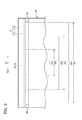
- FIG. 3 is a view of the regulating portion 96 and the supporting member 77 of the induction coil 71 of the fixing unit 9 illustrated in FIG. 2 as seen from the conveyance direction D1 of the sheet of paper T.
- the fixing unit 9 includes a heating rotary belt 9a, a pressing roller 9b as a pressing rotor in pressing contact (abutment) with the heating rotary belt 9a, the heating unit 70, a pressing member 92 and a plurality of temperature sensors 95.
- the heating rotary belt 9a has a circular (endless belt) shape.
- the heating rotary belt 9a is a belt that has a small heat capacity.
- the heating rotary belt 9a can rotate in a first peripheral direction R1 about a second rotational axis J2 that is parallel to a sheet width direction D2.
- the orthogonal direction D2 that is orthogonal to the first peripheral direction R1 is termed "the sheet width direction D2".
- the heating rotary belt 9a uses the heating unit 70 described below to generate heat by induction heating (IH) that employs magnetic induction.
- IH induction heating
- the heating rotary belt 9a is disposed in a region where the magnetic flux generated by the induction coil 71 of the heating unit 70 described below passes. In this manner, the heating rotary belt 9a forms a magnetic path for the magnetic flux generated by the induction coil 71 of the heating unit 70.
- the pressing member 92 is disposed in an inner portion of the heating rotary belt 9a.
- the heating rotary belt 9a is suspended on the pressing member 92.
- the pressing member 92 abuts near the pressing roller 9b described below (in a lower inner portion of the heating rotary belt 9a in the vertical direction) on an inner peripheral surface (inner surface) of the heating rotary belt 9a.
- the heating rotary belt 9a includes a base layer (not illustrated) formed from a magnetic metal layer, an elastic layer formed on the surface of the base layer (not illustrated), and a surface release layer (not illustrated).
- An eddy current (induced current) is generated in the heating rotary belt 9a by electromagnetic induction from a magnetic flux passing through the base layer of the heating rotary belt 9a without penetrating the base layer of the heating rotary belt 9a.
- a Joule heat is generated by electrical resistance of the heating rotary belt 9a by passing the eddy current through the heating rotary belt 9a. In this manner, the heating rotary belt 9a generates heat by reason of an induction heating method (IH) using electromagnetic induction effected by the heating unit 70 described below.
- IH induction heating method
- the base layer is formed from nickel (Ni) having a thickness of 30 - 50 ⁇ m.
- the elastic layer is formed from silicon rubber having a thickness of several hundred ⁇ m.
- the surface release layer is a tube formed from PFA (tetrafluoroethylene-perfluoro alkyl vinyl ether copolymer) having a thickness of tens of ⁇ m.
- the pressing roller 9b has a cylindrical shape (annular shape).
- the pressing roller 9b is disposed facing the heating rotary belt 9a on the lower vertical side of the heating rotary belt 9a.
- the pressing roller 9b can rotate in a second peripheral direction R2 about the first rotation axis J1 that is parallel to the sheet width direction D2.
- the pressing roller 9b extends in the first rotation axis J1 direction.
- the outer peripheral surface of the pressing roller 9b is disposed to abut with the outer peripheral surface (external surface) of the heating rotary belt 9a.
- the pressing roller 9b is disposed to press the pressing member 92 though the heating rotary belt 9a.
- the pressing roller 9b sandwiches a portion of the heating rotary belt 9a with the pressing member 92 to thereby form a fixing nip F with the heating rotary belt 9a.
- the sheet of paper T is sandwiched and conveyed at the fixing nip F.
- the heating rotary belt 9a is subjected to an upward pressing force by the pressing roller 9b and the pressing member 92 (described below) in the direction (vertical direction) of the plane connecting the second rotation axis J2 of the heating rotary belt 9a and the pressing member 92.
- a force that expands the heating rotary belt 9a outwardly acts on the heating rotary belt 9a in a direction that is orthogonal to the plane that connects the second rotation axis J2 of the heating rotary belt 9a and the pressing member 92.
- the pressing roller 9b includes a pressing roller main body 941 and a pair of axial members 942 coaxial to the first rotation axis J1.
- the pressing roller main body 941 includes a cylindrical core member, an elastic layer formed on an outer peripheral surface of the core member, and a release layer formed on an outer peripheral surface of the elastic layer.
- iron is used in the core member.
- foamed silicone rubber is used in the elastic layer.
- a PFA tube is used in the release layer.
- a rotation drive unit (not illustrated) for driving to rotate the pressing roller 9b is connected to one of the axial member 942 of the pressing rollers 9b.
- the pressing roller 9b is driven to rotate at a predetermined speed by the rotation drive unit.
- the heating rotary belt 9a in abutment with the outer peripheral surface of the pressing roller 9b is rotated in response to the rotation of the pressing roller 9b by the rotation and driving action of the rotation drive unit.
- the pressing member 92 is disposed in an inner portion of the heating rotary belt 9a.
- the portion that abuts with the inner peripheral surface of the heating rotary belt 9a of the pressing member 92 is formed from a low-friction layer such as porous glass cloth sheet or the like.
- the pressing member 92 extends along the sheet width direction D2.
- the pressing member 92 abuts with the inner peripheral surface of the heating rotary belt 9a near the pressing roller 9b on the inner portion of the heating rotary belt 9a.
- the pressing member 92 sandwiches the heating rotary belt 9a with the pressing roller 9b to form a fixing nip F between the heating rotary belt 9a and the pressing roller 9b.
- the low-friction layer of the pressing member 92 makes sliding contact with the inner peripheral surface of the heating rotary belt 9a.
- paper passing region is the region through which a sheet of paper T conveyed to the fixing nip F passes in a configuration of being sandwiched by the heating rotary belt 9a and the pressing roller 9b. Furthermore, when the sheet of paper T is conveyed to the fixing nip F, the region on the outer side of the paper passing region through which the sheet of paper T does not pass is termed the "non-paper passing region"
- a maximum paper passing region 901 is set on the outer peripheral surface of the heating rotary belt 9a as a paper passing region through which a sheet of paper T corresponding to the maximum length of the sheet width direction D2 (maximum width) passes when the sheet of paper T is conveyed to the fixing nip F.
- the length in a direction parallel to the sheet width direction D2 of the maximum paper passing region 901 is termed the "maximum paper passing width W1".
- a minimum paper passing region 903 is set on the outer peripheral surface of the heating rotary belt 9a as a paper passing region through which a sheet of paper T corresponding to the minimum length of the sheet width direction D2 (minimum width) passes when the sheet of paper T is conveyed to the fixing nip F.
- the length in a direction parallel to the sheet width direction D2 of the minimum paper passing region 903 is termed the "minimum paper passing width W3".
- An intermediate paper passing region 902 is set on the outer peripheral surface of the heating rotary belt 9a as a paper passing region through which a sheet of paper T that has a length in the sheet width direction D2 corresponding to an intermediate length that is shorter than the maximum length and longer than the minimum length (intermediate width) passes when the sheet of paper T is conveyed to the fixing nip F.
- the length in a direction parallel to the sheet width direction D2 of the intermediate paper passing region 902 is termed the "intermediate paper passing width W2".
- the paper passing regions for the sheets of paper T are not limited thereby and may be suitably set corresponding to the size of the sheets of paper T. Furthermore, a pressure-side maximum paper passing region, a pressure-side minimum paper passing region and a pressure-side intermediate paper passing region are set on the outer peripheral surface of the pressing roller 9b corresponding to the maximum paper passing region 901, the minimum paper passing region 903 and the intermediate paper passing region 902 of the heating rotary belt 9a, respectively. However, each of these regions is omitted from the figures.
- the heating unit 70 includes the induction coil 71, a magnetic core portion 72, a supporting member 77 for supporting the induction coil 71, and a regulating portion 96.
- the induction coil 71 is separated from the outer peripheral surface of the heating rotary belt 9a by a predetermined distance, and is disposed along the outer peripheral surface of the heating rotary belt 9a.
- the pre-wound induction coil 71 is disposed on the heating unit 70 so that a longitudinal direction thereof is parallel to the sheet width direction D2.
- the induction coil 71 may be formed by winding wire in an elongated configuration with reference to the sheet width direction D2 viewed in plan (when seen from above FIG. 2 ).
- the induction coil 71 is formed to be longer than the length of the heating rotary belt 9a in the sheet width direction D2.
- the induction coil 71 When the induction coil 71 is disposed on the heating unit 70, the induction coil 71 are formed so that the disposition described below is realized.
- the inner peripheral edge of the induction coil 71 (the position at which the wire 711A is disposed) enclose a central region 718.
- the wire configuring the induction coil 71 extend in the sheet width direction D2. Furthermore, the wire configuring the induction coil 71 is aligned from the inner peripheral edge of the induction coil 71 in the peripheral direction of the heating rotary belt 9a.
- the outer peripheral edge of the induction coil 71 (the position at which the wire 711B is disposed) faces the outer peripheral surface of the heating rotary belt 9a.
- the supporting member 77 is separated from the heating rotary belt 9a facing the heating rotary belt 9a on an upper side in a vertical direction of the heating rotary belt 9a.
- the supporting member 77 is formed in an arcuate configuration along the outer peripheral surface of the heating rotary belt 9a on an upper side in a vertical direction of the heating rotary belt 9a.
- the arcuate portion of the supporting member 77 extends in a range of approximately 180° in an angle about the second rotation axis J2 of the heating rotary belt 9a.
- the supporting member 77 is elongated in the sheet width direction D2, and has a length that is substantially the same as the length of the sheet width direction D2 of the induction coil 71.
- the supporting member 77 includes a holding portion 771 and a cover portion 772.
- the holding portion 771 and the cover portion 772 are viewed from the sheet width direction D2, the holding portion 771 and the cover portion 772 are formed from a plate member curving in an arcuate configuration.
- the holding portion 771 is disposed facing the outer peripheral surface of the heating rotary belt 9a on the side of the heating rotary belt 9a relative to the induction coil 71.
- the holding portion 771 supports the induction coil 71 to be retained at a predetermined position.
- the cover portion 772 is disposed on the opposite side of the heating rotary belt 9a relative to the induction coil 71.
- the cover portion 772 is disposed to cover the induction coil 71.
- the induction coil 71 is connected to an induction heating circuit (not illustrated). An alternating current from the induction heating circuit is applied to the induction coil 71.
- the induction coil 71 generates a magnetic flux to thereby generate heat in the base layer of the heating rotary belt 9a by application of an alternating current from the induction heating circuit. For example, an alternating current having a frequency of the level of 30kHz is applied to the induction coil 71.
- the magnetic flux generated by the induction coil 71 is introduced into the magnetic path that is the path for magnetic flux formed by the magnetic core portion 72 (described below) and the heating rotary belt 9a.
- the magnetic path is formed by the magnetic core portion 72 (described below) and the heating rotary belt 9a so that the magnetic flux generated by the induction coil 71 revolves in a revolving direction R3.
- the revolving direction R3 is a direction passing along the inner side of the inner peripheral edge 711A and the outer side of the outer peripheral edge 711B of the induction coil 71 to thereby revolve about a portion of the wire of the induction coil 71.
- the magnetic flux generated by the induction coil 71 passes through the magnetic path.
- the magnetic flux generated by the induction coil 71 changes both its intensity and direction due to positive or negative periodic fluctuation of the alternating current since an alternating current is applied from the induction heating circuit (not illustrated).
- An induction current (eddy current) is generated in the heating rotary belt 9a by changes in the magnetic flux.
- the magnetic core portion 72 configures a magnetic path that revolves in the revolving direction R3 as illustrated in FIG.2 .
- the magnetic core portion 72 is disposed in a region for passage of the magnetic flux generated by induction coil 71 and is mainly formed from a ferromagnetic material. As a result, a magnetic path is configured to form a path for magnetic flux generated by the induction coil 71.
- the magnetic core portion 72 includes a center core portion 73, and a pair of side core portions 76.
- the center core portion 73 When viewed in the sheet width direction D2, the center core portion 73 is disposed in a substantially center position of the heating rotary belt 9a with reference to the conveyance direction D1 of the sheet of paper T on an upper side (in proximity to the central region 718) in the vertical direction of the heating rotary belt 9a.
- the center core portion 73 forms a magnetic path with the heating rotary belt 9a in the revolving direction R3 of the magnetic path.
- the center core portion 73 is disposed in proximity to the central region 718 (in proximity to the inner peripheral edge 711A of the induction coil 71).
- the center core portion 73 is separated from the outer peripheral surface of the heating rotary belt 9a by only a predetermined distance and faces the outer peripheral surface of the heating rotary belt 9a.
- the center core portion 73 includes a first opposed surface 731 facing the outer peripheral surface of the heating rotary belt 9a without sandwiching the induction coil 71 therebetween.
- center core portion 73 is formed in substantially a rectangular parallelepiped shape that is elongated with respect to the sheet width direction D2.
- the center core portion 73 is formed in the sheet width direction D2 to be longer than the region corresponding to the maximum paper passing region 901.
- the pair of side core portions 76 forms a magnetic path with the center core portion 73 in the revolving direction R3 of the magnetic path.
- the pair of side core portions 76 is aligned with the center core portion 73 in the revolving direction R3 of the magnetic path.
- the pair of side core portions 76 is disposed in proximity to the outer peripheral edge 711B of the induction coil 71.
- the pair of side core portions 76 is separated from the outer peripheral surface of the heating rotary belt 9a by only a predetermined distance and faces the outer peripheral surface of the heating rotary belt 9a.
- the pair of side core portions 76 includes a second opposed surface 761 facing the outer peripheral surface of the heating rotary belt 9a without sandwiching the induction coil 71 therebetween.
- the pair of side core portions 76 is formed in substantially a rectangular parallelepiped shape that is elongated with respect to the sheet width direction D2.
- the pair of side core portions 76 is formed in the sheet width direction D2 to be longer than the region corresponding to the maximum paper passing region 901.
- the regulating portions 96 abut with the outer peripheral surface of the heating rotary belt 9a. In this manner, the regulating portions 96 regulate the deformation of the heating rotary belt 9a so that the distance between the induction coil 71 and the outer peripheral surface of the heating rotary belt 9a is constant. As illustrated in FIG. 3 , the regulating portions 96 are disposed in proximity to both ends in the sheet width direction D2 of the supporting member 77. The regulating portions 96 are fixed to the supporting member 77. The regulating portions 96 are formed to project from the supporting member 77 towards the heating rotary belt 9a.
- each of the regulating portions 96 is formed by an arcuate first rib 961.
- Each of the arcuate first rib 961 extends in the first peripheral direction R1 along the outer peripheral surface of the heating rotary belt 9a.
- the amount of projection of the first rib 961 is set in consideration of the distance between the induction coil 71 and the outer peripheral surface of the heating rotary belt 9a.
- each of the first rib 961 abuts with the outer peripheral surface of the heating rotary belt 9a along substantially half the circumference of the outer peripheral surface thereof on an upper side in a vertical direction on the heating rotary belt 9a in the non-paper passing region on the outer side of the maximum paper passing region 901. More specifically, each of the first rib 961 is formed to extend in a range of approximately 180° in an angle about the second rotation axis J2 of the heating rotary belt 9a on an upper side from the center portion in a vertical direction on the heating rotary belt 9a. Each of the first rib 961 abuts with and along the outer peripheral surface of the heating rotary belt 9a.
- Each of the first rib 961 is formed continuously from the upstream side of the first peripheral direction R1 of the heating rotary belt 9a (one side) to the downstream side (other side) in a symmetrical configuration to the plane connecting the pressing member 92 with the second rotation axis J2 of the heating rotary belt 9a.
- each of the first rib 961 regulates the deformation of the heating rotary belt 9a in a direction that is orthogonal to the plane connecting the second rotation axis J2 of the heating rotary belt 9a and the pressing member 92. At the same time, each of the first rib 961 regulates the position of the upper portion in a vertical direction of the heating rotary belt 9a relative to the supporting member 77. Thus each of the first rib 961 makes the distance between the induction coil 71 and the outer peripheral surface of the heating rotary belt 9a constant.
- the end 961a of the first rib 961 on the upstream side (downstream side of the conveyance direction D1 of the sheet of paper T) in the first peripheral direction R1 abuts with the outer peripheral surface of the heating rotary belt 9a after gradually approaching the outer peripheral surface of the heating rotary belt 9a from the upstream side of the first peripheral direction R1 towards a downstream side.
- Each of the end 961b on the downstream side (upstream side of the conveyance direction D1 of the sheet of paper T) of the first peripheral direction R1 of the first rib 961 abuts in a substantially vertical configuration with the outer peripheral surface of the heating rotary belt 9a.
- the temperature sensors 95 detect the temperature of the outer peripheral surface of the heating rotary belt 9a.
- the temperature sensor 95 is disposed in a configuration of facing but not making contact with the outer peripheral surface of the heating rotary belt 9a.
- the power source of the printer 1 when the power source of the printer 1 is switched to the ON position, power is supplied respectively to the charging units 10a, 10b, 10c and 10d, the laser scanner units 4a, 4b, 4c and 4d, the developing units 16a, 16b, 16c and 16d, the primary transfer rollers 37a, 37b, 37c and 37d, the secondary transfer roller 8, the printer control unit (not illustrated), and the fixing unit 9.
- Control signals from the printer control unit are used in the controls of the respective operation of the charging units 10a, 10b, 10c and 10d, the laser scanner units 4a, 4b, 4c and 4d, the developing units 16a, 16b, 16c and 16d, the primary transfer rollers 37a, 37b, 37c and 37d, the secondary transfer roller 8, the intermediate transfer belt 7, and the fixing unit 9.
- the reception unit (not illustrated) of the printer 1 receives image formation instruction information when the power source of the printer 1 is in the ON position.
- the image formation instruction information is information generated based on the operation of an operation unit (not illustrated) that is disposed, for example, in an external portion of the printer 1.
- the printer 1 starts the printing operation.
- the sheet of paper T that is fed from the pair of registration rollers 80 passes through the first conveyance path L1 and is conveyed to the transfer nip N2 between the intermediate transfer belt 7 and the secondary transfer roller 8.
- the charging units 10a, 10b, 10c and 10d negatively charges (negative polarity) or positively charges (positive polarity) the surface of each of the photoreceptor drums 2a, 2b, 2c and 2d in a uniform manner, respectively.
- the laser scanner units 4a, 4c, 4c and 4d irradiate laser light from a laser light source (not illustrated) toward the respective photoreceptor drums 2a, 2b, 2c and 2d.
- the laser scanner units 4a, 4b, 4c and 4d perform scanning exposure of the surface of each of the photoreceptor drums 2a, 2b, 2c and 2d, and then the charge is removed. In this manner, an electrostatic latent image is formed on the respective surfaces of the photoreceptor drums 2a, 2b, 2c and 2d.
- the developing units 16a, 16b, 16c and 16d causes a toner of respective colors to adhere to the electrostatic latent image formed on the surface of each of the photoreceptor drums 2a, 2b, 2c and 2d, thereby forming a color toner image on the surface of each of the photoreceptor drums 2a, 2b, 2c and 2d.
- a toner image of each color which is formed on each of the photoreceptor drums 2a, 2b, 2c and 2d, is sequentially subjected to the primary transfer to the intermediate transfer belt 7. In this manner, a full color toner image is formed on the intermediate transfer belt 7.
- the toner image is transferred onto the sheet of paper T that passes through the transfer nip N2 between the intermediate transfer belt 7 and the secondary transfer roller 8.
- the sheet of paper T with the transferred toner image is conveyed through the second conveyance path L2 towards the fixing unit 9. More specifically, the sheet of paper T with the transferred toner image is conveyed towards the fixing nip F that is formed by the heating rotary belt 9a and the pressing roller 9b of the fixing unit 9.
- the pressing roller 9b is driven to rotate by the rotating drive unit (not illustrated).
- the heating rotary belt 9a is driven to rotate by the rotation of the pressing roller 9b.
- an alternating current is applied to the induction coil 71 from the induction heating circuit (not illustrated).
- the induction coil 71 generates a magnetic flux, thereby generating heat in the heating rotary belt 9a.
- the magnetic flux generated by the induction coil 71 passes (revolves) through the revolving direction R3 to connect the inner side of the inner peripheral edge 711A and the outer side of the outer peripheral edge 711B of the induction coil 71 in the magnetic path that is formed by the heating rotary belt 9a, the center core portion 73 and the pair of side core portions 76.
- An eddy current (induction current) is generated by electromagnetic induction in the base layer of the heating rotary belt 9a due to variations in the direction and the intensity of the magnetic flux passing through the magnetic path.
- the eddy current passes through the base layer of the heating rotary belt 9a to thereby generate Joule heat because the base layer of the heating rotary belt 9a has its electrical resistance and, as a result, the heating rotary belt 9a generates heat.
- the rotation of the heating rotary belt 9a displaces the portion (base layer) that is heated by electromagnetic induction heating (IH) in the heating rotary belt 9a in a sequential manner toward the fixing nip F formed by the heating rotary belt 9a and the pressing roller 9b of the fixing unit 9.
- the printer 1 controls the induction heating circuit (not illustrated) so that temperature at the fixing nip F becomes a predetermined temperature.
- the sheet of paper T with the toner image is introduced into the fixing nip F of the fixing unit 9. In this manner, the toner is melted in the fixing nip F to thereby fixing the toner to the sheet of paper T.
- a pressing force is applied to the heating rotary belt 9a in an upward vertical direction as a result of the pressing member 92 that abuts with the inner peripheral surface of the heating rotary belt 9a and the annular pressing roller 9b that is disposed facing the heating rotary belt 9a.
- a force that expands the heating rotary belt 9a outwardly acts on the heating rotary belt 9a in a direction that is orthogonal to the plane that connects the second rotation axis J2 of the heating rotary belt 9a and the pressing member 92.
- the regulating portions 96 are formed by the arcuate first ribs 961 as described above.
- the first ribs 961 are formed across the upstream side of the first peripheral direction R1 of the heating rotary belt 9a (one side) to the downstream side (other side) in a symmetrical configuration to the plane connecting the central portion of pressing member 92 with respect to the conveyance direction D1 of the sheet of paper T with the second rotation axis J2 of the heating rotary belt 9a.
- the first ribs 961 abut with the outer peripheral surface of the heating rotary belt 9a to thereby sandwich the heating rotary belt 9a from the upstream and downstream sides with respect to the conveyance direction D1 of the sheet of paper T
- the first ribs 961 regulate the deformation of the heating rotary belt 9a.
- the arcuate first ribs 961 abut along the outer peripheral surface of the heating rotary belt 9a on an upper side from the central portion in a vertical direction on the heating rotary belt 9a. Consequently, each of the first rib 961 regulates the deformation of the heating rotary belt 9a and regulates the position of the portion in an upward vertical direction of the heating rotary belt 9a so that the distance between the outer peripheral surface of the heating rotary belt 9a and the induction coil 71 becomes constant. In this manner, the heating efficiency of the fixing unit 9 is stabilized. Furthermore, the heating time during startup of the fixing unit 9 can be stabilized.
- the regulating portions 96 abut with the heating rotary belt 9a in the non-paper passing region on the outer side of the maximum paper passing region 901. As a result, heat loss by the regulating portions 96 in the paper passing region of the heating rotary belt 9a can be suppressed and the regulating portion 96 can stabilize the heating efficiency of the fixing unit 9. Furthermore, the startup time of the fixing unit 9 can be stabilized.
- the upstream end 961a of the arcuate first ribs 961 in the first peripheral direction R1 gradually approach the outer peripheral surface of the heating rotary belt 9a from the upstream side of the first peripheral direction R1 of the heating rotary belt 9a towards the downstream side.
- catching of the heating rotary belt 9a on the end 961a of the regulating portion 96 during rotation is reduced.
- the regulating portions 96 abut in a configuration in which almost no damage is caused to the heating rotary belt 9a. Therefore, the regulating portions 96 can rotate the heating rotary belt 9a smoothly.
- the printer 1 includes the arcuate heating rotary belt 9a, the pressing member 92 that abuts with the inner surface of the heating rotary belt 9a, the pressing roller 9b that forms the fixing nip F with the heating rotary belt 9a, the induction coil 71 that is disposed with a predetermined distance from the outer peripheral surface of the heating rotary belt 9a and generate a magnetic flux to generate heat in the heating rotary belt 9a, the magnetic core portion 72 that forms a magnetic path for magnetic flux generated by the induction coil 71, and a first ribs 961 that regulate the deformation of the heating rotary belt 9a by abutment with the outer peripheral surface of the heating rotary belt 9a.
- the first ribs 961 in the printer 1 according to the present embodiment are disposed on the supporting member 77.
- the deformation of the heating rotary belt 9a is regulated with a simple configuration in which only the first ribs 961 are provided on the supporting member 77.
- the projection amount of the first rib 961 in the printer 1 according to the present embodiment is set in consideration of the distance between the induction coil 71 and the outer peripheral surface of the heating rotary belt 9a. Consequently, a heating design for the fixing unit 9 is easily enabled by simply adjusting the projection amount of the first rib 961. In this manner, the heating efficiency of the fixing unit 9 can be stabilized. As a result, the startup time of the fixing unit 9 can be stabilized.
- FIG. 4 is a sectional view illustrating respective constituent elements of the fixing unit 9 in the printer 1 according to the second embodiment of the present disclosure.
- FIG. 5 is a perspective view of the heating unit 70 of the fixing unit 9 illustrated in FIG. 4 .
- the shape of the regulating portion 96 and the position of the regulating portion 96 largely differ from the first embodiment.
- each of the regulating portion 96 in the second embodiment includes two substantially hemispherical second ribs 962.
- the two second ribs 962 are disposed in proximity to both ends in the sheet conveyance direction D1 of the supporting member 77 of the heating unit 70.
- the two second ribs 962 are integrally formed with the supporting member 77.
- the hemispherical tip portion of the two second ribs 962 abuts with the outer peripheral surface of the heating rotary belt 9a in the non-paper passing region on the outer side of the maximum paper passing region 901.
- the two second ribs 962 are separately disposed at the upstream side of the first peripheral direction R1 (one side) and at the downstream side (other side) in a symmetrical configuration to the plane connecting the pressing member 92 with the second rotation axis J2 of the heating rotary belt 9a.
- the two second ribs 962 are separately disposed each other in a direction that is substantially orthogonal to the plane connecting the pressing member 92 with the second rotation axis J2 of the heating rotary belt 9a.
- the two second ribs 962 are disposed with a separation of substantially 180°in an angle ⁇ 1 centering on the second rotation axis J2 of the heating rotary belt 9a on the side of the induction coil 71 with respect to the outer peripheral surface of the heating rotary belt 9a. As a result, the two second ribs 962 abut with a portion that is associated with a high probability of maximum deformation of the heating rotary belt 9a.
- the two second ribs 962 abut with the outer peripheral surface of the heating rotary belt 9a to press the central portion in a vertical direction of the heating rotary belt 9a towards the inner side of the heating rotary belt 9a and thereby sandwich the heating rotary belt 9a from the upstream and downstream side in the conveyance direction D1 of the sheet of paper T.
- the two second ribs 962 regulate the position of the heating rotary belt 9a with respect to the supporting member 77 by regulating the deformation of the heating rotary belt 9a. Therefore, the two second ribs 962 can keep the distance between the induction coil 71 supported by the supporting member 77 and the outer peripheral surface of the heating rotary belt 9a constant. In this manner, the heating efficiency of the fixing unit 9 is stabilized. Furthermore, the heating time during startup of the fixing unit 9 can be stabilized.
- the regulating portion 96 in the fixing unit 9 of the printer 1 according to the second embodiment is configured by two substantially hemispherical ribs 962.
- the two second ribs 962 are separately disposed each other in a direction that is substantially orthogonal to the plane connecting the pressing member 92 with the second rotation axis J2 of the heating rotary belt 9a.
- the two second ribs 962 press the central portion in a vertical direction of the heating rotary belt 9a towards the inner side of the heating rotary belt 9a and thereby sandwich the heating rotary belt 9a from the upstream and downstream side in the conveyance direction D1 of the sheet of paper T.
- the two second ribs 962 can stably regulate the deformation of the heating rotary belt 9a. Therefore, the distance between the induction coil 71 and the outer peripheral surface of the heating rotary belt 9a can be kept constant.
- the two second ribs 962 are disposed with a separation of substantially 180°in an angle ⁇ 1 centering on the second rotation axis J2 of the heating rotary belt 9a on the side of the induction coil 71 with respect to the outer peripheral surface of the heating rotary belt 9a.
- the two second ribs 962 abut with a portion that is associated with a high probability of maximum deformation of the heating rotary belt 9a.
- the two second ribs 962 can further regulate the deformation of the heating rotary belt 9a.
- the heating efficiency of the fixing unit 9 is further stabilized.
- the heating time during startup of the fixing unit 9 can be further stabilized.
- the spherical tip of the two second ribs 962 abuts with the outer peripheral surface of the heating rotary belt 9a.
- the distance between the induction coil 71 and the outer peripheral surface of the heating rotary belt 9a can be kept constant in a configuration in which damage such as marking of the heating rotary belt 9a by contact with the two second rib 962 is reduced.
- FIG. 6 is a sectional view illustrating respective constituent elements of the fixing unit 9 in the printer 1 according to the third embodiment of the present disclosure.
- the main difference of the third embodiment in relation to the second embodiment is that the supporting member 77 of the heating unit 70 is formed in an arcuate shape of approximately 120° in an angle centering on the second rotation shaft J2 of the heating rotary belt 9a, and that the regulating portion 96 is configured by hemispherical third ribs 963A, 963A, 963B.
- the three hemispherical third ribs 963A, 963A, 963B are disposed in a range of approximately 120° in an angle ⁇ 2 centering on the second rotation shaft J2 of the heating rotary belt 9a.
- the three third ribs 963A, 963A, 963B are disposed respectively separated on the upstream end, the downstream end and an intermediate position in the first peripheral direction R1 on the holding portion 771 of the supporting member 77.
- the spherical tip portions of the three substantially hemispherical third ribs 963A, 963A, 963B abut with three positions on the outer peripheral surface of the heating rotary belt 9a on the non-paper passing region on the outer side of the maximum paper passing region 901.
- the third ribs 963A, 963A are disposed on the upstream end and the downstream end in the first peripheral direction R1 of the holding portion 771 of the supporting member 77.
- the third ribs 963A, 963A on the upstream end and the downstream end are disposed in a range of approximately 120° in an angle ⁇ 2 centering on the second rotation shaft J2 of the heating rotary belt 9a on the side of induction coil 71 with respect to the outer peripheral surface of the heating rotary belt 9a.
- the two third ribs 963A, 963A abut with a portion that is associated with a probability of deformation of the heating rotary belt 9a.
- the third ribs 963A, 963A on the upstream end and the downstream end abut with the outer peripheral surface of the heating rotary belt 9a and regulate the deformation of the heating rotary belt 9a.
- the third rib 963B is disposed at an intermediate position between the upstream end and the downstream end of the holding portion 771 of the supporting member 77.
- the third rib 963B at the intermediate position abuts with the outer peripheral surface of the heating rotary belt 9a in the uppermost portion in the vertical direction of the heating rotary belt 9a to regulate the position of the outer peripheral surface of the heating rotary belt 9a relative to the supporting member 77.
- the third ribs 963A, 963A on the upstream end and the downstream end in the fixing unit 9 of the printer 1 according to the third embodiment are separated by approximately 120° in an angle ⁇ 2 centering on the second rotation shaft J2 of the heating rotary belt 9a on the side of the induction coil 71 with respect to the outer peripheral surface of the heating rotary belt 9a.
- the two third ribs 963A, 963A abut with the portion of the heating rotary belt 9a that deforms.
- the two third ribs 963A, 963A abut with the outer peripheral surface of the heating rotary belt 9a to regulate the deformation of the heating rotary belt 9a.
- the heating efficiency of the fixing unit 9 is stabilized.
- the heating time during startup of the fixing unit 9 can be stabilized.
- the third rib 963B at the intermediate position regulates the position of the outer peripheral surface of the heating rotary belt 9a relative to the supporting member 77 between the two third ribs 963A, 963A on the upstream end and the downstream end.
- the three third ribs 963A, 963A, 963B overall regulate the position of the heating rotary belt 9a to thereby keep the distance between the induction coil 71 and the outer peripheral surface of the heating rotary belt 9a constant. In this manner, the heating efficiency of the fixing unit 9 is further stabilized. Furthermore, the heating time during startup of the fixing unit 9 can be further stabilized.
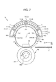
- FIG. 7 is a sectional view illustrating respective constituent elements of the fixing unit 9 in the printer 1 according to the fourth embodiment of the present disclosure.
- the main difference in relation to the first to the third embodiment is in the shape of the regulating portion 96 and the position of the regulating portion 96.
- the regulating portion 96 in the fixing unit 9 of the printer 1 is configured from two cylindrical rollers 964.
- the two cylindrical rollers 964 are disposed in proximity to both ends of the supporting member 77 of the heating unit 70 with reference to the sheet conveyance direction D1.
- the two cylindrical rollers 964 are rotatably supported by a shaft member 965 provided on the supporting member 77.
- the two cylindrical rollers 964 are separately disposed on the upstream and downstream sides in the first peripheral direction R1 in a symmetrical configuration to the plane connecting the pressing member 92 with the second rotation axis J2 of the heating rotary belt 9a. More precisely, the two cylindrical rollers 964 are disposed with a separation of substantially 180°in an angle ⁇ 2 centering on the second rotation axis J2 of the heating rotary belt 9a.
- the outer peripheral surface of the two cylindrical rollers 964 abut with the outer peripheral surface of the heating rotary belt 9a in the non-paper passing region on the outer side of the maximum paper passing region 901. Therefore the two cylindrical rollers 964 are driven to rotate about the axial member 965 by the rotation of the heating rotary belt 9a.
- the printer 1 according to the fourth embodiment By using the printer 1 according to the fourth embodiment, the following effects can be obtained in addition to the effects exhibited by the first embodiment to the third embodiment.
- the regulating portion 96 of the fixing unit 9 of the printer 1 according to the fourth embodiment is configured by two cylindrical rollers 964 that are driven to rotate by the rotation of the heating rotary belt 9a.
- the cylindrical rollers 964 as a regulating portion 96 enable a reduction in the contact resistance with the heating rotary belt 9a.
- the two cylindrical rollers 964 enable a reduction in the possibility of damage such as marking on the heating rotary belt 9a caused by contact with the heating rotary belt 9a. Therefore, while the heating rotary belt 9a smoothly rotates, and deformation of the heating rotary belt 9a is regulated to thereby keep the distance between the induction coil 71 and the outer peripheral surface of the heating rotary belt 9a constant.
- the regulating portion 96 was configured by three third ribs 963, the regulating portion may be configured by four or more ribs.
- the regulating portion 96 was configured by two cylindrical rollers 964, the regulating portion 96 may be configured by three or more cylindrical rollers.
- the sheet-shaped transfer material is not limited to paper, and may for example be a film sheet.
Landscapes
- Physics & Mathematics (AREA)
- General Physics & Mathematics (AREA)
- Fixing For Electrophotography (AREA)
Abstract
Description
- This application is based on and claims the benefit of priority from Japanese Patent Application No.
2011-002266, filed on 7 January 2011 - The present disclosure relates to a fixing unit and an image forming apparatus provided with same.
- Conventionally, reduction in startup time and energy efficiency are desirable features for an image forming apparatus such as a printer, a copier, or the like. Therefore considerable attention has been attracted by a fixing unit that uses a heating rotary belt enabling a reduction in the heat capacity.
- Furthermore, considerable attention has been directed to a fixing unit that uses an induction heating method (IH) for generating heat in a heat generating layer of the heating rotary belt by an electromagnetic induction action due to magnetic flux generated by an induction coil.
- A fixing unit using a heating rotary belt includes a heating rotary belt, a pressing member, and a pressure rotor. The pressing member is disposed in an inner portion of the heating rotary belt, and abuts with an inner surface of the heating rotary belt. The pressure rotor sandwiches the heating rotary belt with the pressing member and is opposed to the heating rotary belt. The heating rotary belt may deform into an ellipse shape upon application of a pressing force from the pressure rotor to thereby expand in a direction orthogonal to the direction of pressure from the pressure rotor. The heating rotary belt may deform by a deformation amount as a result of the fluctuation in the intensity of the pressing force from the pressure rotor.
- As described above, deformation of the heating rotary belt may be caused in a fixing unit that includes a combination of an induction heating method (IH) and a heating rotary belt. Consequently, heating efficiency in the fixing unit may vary in response to a fluctuation in the distance between the induction coil and the outer peripheral surface of the heating rotary belt. As a result, it has sometimes not been possible to stabilize the temperature increase time when starting up the fixing unit.
- However, there is a fixing unit that stabilizes a heating efficiency by enabling an adjustment of the distance between the induction coil and the outer peripheral surface of the heating rotary belt by displacement of a support member that supports the induction coil.
- A configuration to enable displacement of the supporting member in a fixing unit as described above is complicated. Furthermore, this type of fixing unit does not enable a reduction in the deformation of the heating rotary belt.
- The present disclosure has the object of providing a fixing unit that enables stabilization of the heating efficiency in the fixing unit by regulating the deformation of the heating rotary belt with a simple configuration.
- It is a further object of the present disclosure to provide an image forming apparatus that includes the fixing unit.
- A fixing unit according to the present disclosure includes a heating rotary belt, a pressing member, a pressing rotor, a induction coil, a magnetic core portion and a regulating portion. The pressing member is disposed in an inner portion of the heating rotary belt and abuts with an inner surface of the heating rotary belt. The pressing rotor is disposed facing the heating rotary belt and is configured to form a fixing nip with the heating rotary belt by sandwiching the heating rotary belt with the pressing member. The induction coil is separated from an external surface of the heating rotary belt and disposed along the external surface and is configured to generate a magnetic flux to generate heat in the heating rotary belt. The magnetic core portion is configured to form a magnetic path for the magnetic flux generated by the induction coil. The regulating portion is configured to regulate the deformation of the heating rotary belt by abutment with the external surface of the heating rotary belt.
-
-
FIG. 1 illustrates the disposition of respective constituent elements in a printer according to a first embodiment of the present disclosure. -
FIG. 2 is a sectional view illustrating the respective constituent elements in a fixing unit in the printer according to the first embodiment. -
FIG. 3 is a view of a regulating portion and a supporting member of a induction coil of the fixing unit illustrated inFIG. 2 as seen from the conveyance direction of a sheet of paper. -
FIG. 4 is a sectional view illustrating respective constituent elements of a fixing unit in a printer 1 according to a second embodiment of the present disclosure. -
FIG. 5 is a perspective view of a heating unit of the fixing unit illustrated inFIG. 4 . -
FIG. 6 is a sectional view illustrating respective constituent elements of a fixing unit in a printer according to a third embodiment of the present disclosure. -
FIG. 7 is a sectional view illustrating respective constituent elements of a fixing unit in a printer according to a fourth embodiment of the present disclosure. - A first embodiment of an image forming apparatus according to the present disclosure will be described below with reference to the figures.
- The overall structure of the printer 1 will be described with reference to
FIG. 1 as an example of the image forming apparatus according to the first embodiment.FIG. 1 illustrates the disposition of respective constituent elements in the printer 1 according to the first embodiment of the present disclosure. In the following description, the perpendicular direction inFIG. 1 may simply be expressed as a "vertical direction". - As illustrated in
FIG. 1 , the printer 1 according to the first embodiment includes a main body M. The main body M includes an image forming unit GK and a paper feeding/discharging portion KH. The image forming unit GK forms a toner image on a sheet of paper T as a sheet-shaped transfer material on the base of image information. The paper feeding/discharging portion KH feeds the paper sheet T to the image forming unit GK and discharges the paper sheet T with the toner image formed thereon. - The outer shape of the main body M is configured by the case BD as a housing.
- As illustrated in
FIG. 1 , the image forming unit GK includesphotoreceptor drums charging units laser scanner units units toner cartridges toner supply units drum cleaning units neutralization units secondary transfer roller 8, anopposing roller 18, and thefixing unit 9. - As illustrated in
FIG. 1 , the paper feeding/discharging portion KH includes apaper feed cassette 52, a conveyance path L of the sheet of paper T, a pair ofregistration rollers 80, a plurality of rollers or pair of rollers, and apaper discharging unit 50. - Hereafter, the configuration of the image forming unit GK and the paper feeding/discharging portion KH will be described in detail.
- First, the image forming unit GK will be described.
- In the image forming unit GK, in the following order on the surface of the
photoreceptor drums charging units laser scanner unit units primary transfer rollers neutralization units drum cleaning units photoreceptor drums - In addition, in the image forming unit GK, secondary transfer is performed by the intermediate transfer belt 7, the
secondary transfer roller 8 and theopposing roller 18, and fixing is performed by thefixing unit 9. - Each of the
photoreceptor drums photoreceptor drums photoreceptor drums - Each of the
charging units photoreceptor drums charging units photoreceptor drums - The
laser scanner units photoreceptor drums - Each of the
laser scanner units photoreceptor drums photoreceptor drums laser scanner units photoreceptor drums - The developing
units photoreceptor drums units photoreceptor drums photoreceptor drums units units photoreceptor drums - The
toner cartridges units units toner cartridges - The
toner supply units toner cartridges units toner supply units toner cartridges units - A toner image of each color, which is formed on the surface of each of the
photoreceptor drums roller 35, the opposingroller 18 that functions as a driving roller, atension roller 36, and the like. Thetension roller 36 applies a force from an inner side to an outer side of the intermediate transfer belt 7. As a result, a predetermined tension is imparted to the intermediate transfer belt 7. - Each of the
primary transfer rollers photoreceptor drums - The intermediate transfer belt 7 is sandwiched between each of the
primary transfer rollers photoreceptor drums photoreceptor drums photoreceptor drums primary transfer rollers photoreceptor drums - Each of the
neutralization units photoreceptor drums - Each of the
drum cleaning units photoreceptor drums - The
secondary transfer roller 8 causes the full color toner image primarily transferred to the intermediate transfer belt 7 to be secondarily transferred to a sheet of paper T. A secondary transfer bias for causing the full color toner image formed on the intermediate transfer belt 7 to be transferred to the sheet of paper T is applied to thesecondary transfer roller 8 by a secondary transfer bias application unit (not illustrated). - The
secondary transfer roller 8 is configured to come in contact with or be separated from the intermediate transfer belt 7. More specifically, thesecondary transfer roller 8 is configured to be movable between a contact position in abutment with the intermediate transfer belt 7 and a separate position separated from the intermediate transfer belt 7. - The opposing
roller 18 is arranged opposite thesecondary transfer roller 8 relative to the intermediate transfer belt 7. The intermediate transfer belt 7 is sandwiched by thesecondary transfer roller 8 and the opposingroller 18. The sheet of paper T is pressed against the outside surface (the surface where the toner image is primarily transferred) of the intermediate transfer belt 7. A secondary transfer nip N2 is formed between the intermediate transfer belt 7 and thesecondary transfer roller 8. At the secondary transfer nip N2, the full color toner image primarily transferred to the intermediate transfer belt 7 is secondarily transferred to the sheet of paper T. - The fixing
unit 9 melts and pressurizes the toners of respective colors forming the toner image that has been secondarily transferred to the sheet of paper T, and fixes the toner image on the sheet of paper T. - The fixing
unit 9 will be described in detail below. - Next, the paper feeding/discharging portion KH will be described.
- As illustrated in
FIG. 1 , thepaper feed cassette 52 that stores sheets of paper T is arranged in a lower part of the main body M.A mounting plate 60 for placing sheets of paper T is arranged in thepaper feed cassette 52. A sheet of paper T stacked on the mountingplate 60 is fed to the conveyance path L by thecassette feeder 51. Thecassette feeder 51 includes a double-feed prevention mechanism that is composed of aforward feed roller 61, and a pair offeed rollers 81. Theforward feed roller 61 picks up a sheet of paper T from the mountingplate 60. The pair offeed rollers 81 feed the sheet of paper T to the conveyance path L on a sheet by sheet basis. - The conveyance path L for conveying the sheet of paper T includes the first conveyance path L1, the second conveyance path L2, the third conveyance path L3 and the return conveyance path Lb. The first conveyance path L1 is a conveyance path from the
cassette feeder 51 to the secondary transfer nip N2. The second conveyance path L2 is a conveyance path from the secondary transfer nip N2 to the fixingunit 9. The third conveyance path L3 is a conveyance path from the fixingunit 9 to thepaper discharging unit 50. The return conveyance path Lb is a conveyance path that causes a sheet of paper, which is conveyed on the third conveyance path L3 from downstream to upstream, to be turned upside down and conveyed back to the first conveyance path L1. - In addition, a first joint portion P1 and a second joint portion P2 are formed midway on the first conveyance path L1. A first branch portion Q1 is formed midway on the third conveyance path L3.
- A paper detection sensor (not illustrated) and the pair of
registration rollers 80 are disposed midway on the first conveyance path L1 (more specifically between the second joint portion P2 and the secondary transfer nips N2). The paper detection sensor is a sensor for detecting the sheet of paper T. The pair ofregistration rollers 80 is configured to correct skew (diagonal paper feed) of the sheet of paper T and to adjust the timing of feeding the sheet of paper and the formation of a toner image at the image forming unit GK. - A pair of
intermediate rollers 82 is arranged between the first joint portion P1 and the second joint portion P2 in the first conveyance path L1. The pair ofintermediate rollers 82 is arranged downstream of the pair ofpaper feed rollers 81. The pair ofintermediate rollers 82 sandwiches the sheet of paper T that is conveyed by the pair ofpaper feed rollers 81, and conveys the sheet of paper T to the pair ofregistration rollers 80. - A
branch member 58 is provided at the first branch portion Q1. Thebranch member 58 causes the conveyance direction of a sheet of paper T conveyed from the fixingunit 9 through the third conveyance path L3 from upstream to downstream to branch off towards thepaper discharging unit 50. Thebranch member 58 causes the conveyance direction of a sheet of paper T conveyed from thepaper discharging unit 50 through the third conveyance path L3 from downstream to upstream to branch off towards the return conveyance path Lb. - The
paper discharging unit 50 is formed at an end with reference to the paper conveyance direction of the third conveyance path L3. Thepaper discharging unit 50 is arranged at an upper part of the main body M. Thepaper discharging unit 50 discharges the sheet of paper T outside the main body M. - A discharged paper accumulating portion M1 is formed at an opening side of the
paper discharging unit 50. The discharged paper accumulating portion M1 is formed on a top surface (external surface) of the main body M. Sensors for paper detection are arranged at predetermined locations in the respective conveyance paths. - Next, the configuration of the fixing
unit 9 that is the characteristic unit of the printer 1 according to the first embodiment will be described in detail.FIG. 2 is a sectional view illustrating the respective constituent elements in the fixingunit 9 in the printer 1 according to the first embodiment.FIG. 3 is a view of the regulatingportion 96 and the supportingmember 77 of theinduction coil 71 of the fixingunit 9 illustrated inFIG. 2 as seen from the conveyance direction D1 of the sheet of paper T. - As illustrated in
FIG. 2 , the fixingunit 9 includes aheating rotary belt 9a, apressing roller 9b as a pressing rotor in pressing contact (abutment) with theheating rotary belt 9a, theheating unit 70, a pressingmember 92 and a plurality oftemperature sensors 95. - The
heating rotary belt 9a has a circular (endless belt) shape. Theheating rotary belt 9a is a belt that has a small heat capacity. Theheating rotary belt 9a can rotate in a first peripheral direction R1 about a second rotational axis J2 that is parallel to a sheet width direction D2. In the present embodiment, the orthogonal direction D2 that is orthogonal to the first peripheral direction R1 is termed "the sheet width direction D2". Theheating rotary belt 9a uses theheating unit 70 described below to generate heat by induction heating (IH) that employs magnetic induction. - The
heating rotary belt 9a is disposed in a region where the magnetic flux generated by theinduction coil 71 of theheating unit 70 described below passes. In this manner, theheating rotary belt 9a forms a magnetic path for the magnetic flux generated by theinduction coil 71 of theheating unit 70. - The pressing
member 92 is disposed in an inner portion of theheating rotary belt 9a. Theheating rotary belt 9a is suspended on the pressingmember 92. The pressingmember 92 abuts near thepressing roller 9b described below (in a lower inner portion of theheating rotary belt 9a in the vertical direction) on an inner peripheral surface (inner surface) of theheating rotary belt 9a. - The
heating rotary belt 9a includes a base layer (not illustrated) formed from a magnetic metal layer, an elastic layer formed on the surface of the base layer (not illustrated), and a surface release layer (not illustrated). An eddy current (induced current) is generated in theheating rotary belt 9a by electromagnetic induction from a magnetic flux passing through the base layer of theheating rotary belt 9a without penetrating the base layer of theheating rotary belt 9a. A Joule heat is generated by electrical resistance of theheating rotary belt 9a by passing the eddy current through theheating rotary belt 9a. In this manner, theheating rotary belt 9a generates heat by reason of an induction heating method (IH) using electromagnetic induction effected by theheating unit 70 described below. In the present embodiment, the base layer is formed from nickel (Ni) having a thickness of 30 - 50 µm. The elastic layer is formed from silicon rubber having a thickness of several hundred µm. The surface release layer is a tube formed from PFA (tetrafluoroethylene-perfluoro alkyl vinyl ether copolymer) having a thickness of tens of µm. - The
pressing roller 9b has a cylindrical shape (annular shape). Thepressing roller 9b is disposed facing theheating rotary belt 9a on the lower vertical side of theheating rotary belt 9a. Thepressing roller 9b can rotate in a second peripheral direction R2 about the first rotation axis J1 that is parallel to the sheet width direction D2. Thepressing roller 9b extends in the first rotation axis J1 direction. - The outer peripheral surface of the
pressing roller 9b is disposed to abut with the outer peripheral surface (external surface) of theheating rotary belt 9a. Thepressing roller 9b is disposed to press the pressingmember 92 though theheating rotary belt 9a. Thepressing roller 9b sandwiches a portion of theheating rotary belt 9a with the pressingmember 92 to thereby form a fixing nip F with theheating rotary belt 9a. The sheet of paper T is sandwiched and conveyed at the fixing nip F. - The
heating rotary belt 9a is subjected to an upward pressing force by thepressing roller 9b and the pressing member 92 (described below) in the direction (vertical direction) of the plane connecting the second rotation axis J2 of theheating rotary belt 9a and the pressingmember 92. In this manner, a force that expands theheating rotary belt 9a outwardly acts on theheating rotary belt 9a in a direction that is orthogonal to the plane that connects the second rotation axis J2 of theheating rotary belt 9a and the pressingmember 92. - The
pressing roller 9b includes a pressing rollermain body 941 and a pair ofaxial members 942 coaxial to the first rotation axis J1. The pressing rollermain body 941 includes a cylindrical core member, an elastic layer formed on an outer peripheral surface of the core member, and a release layer formed on an outer peripheral surface of the elastic layer. In the present embodiment, iron is used in the core member. Furthermore, foamed silicone rubber is used in the elastic layer. A PFA tube is used in the release layer. - A rotation drive unit (not illustrated) for driving to rotate the
pressing roller 9b is connected to one of theaxial member 942 of thepressing rollers 9b. Thepressing roller 9b is driven to rotate at a predetermined speed by the rotation drive unit. Theheating rotary belt 9a in abutment with the outer peripheral surface of thepressing roller 9b is rotated in response to the rotation of thepressing roller 9b by the rotation and driving action of the rotation drive unit. - The pressing
member 92 is disposed in an inner portion of theheating rotary belt 9a. The portion that abuts with the inner peripheral surface of theheating rotary belt 9a of the pressingmember 92 is formed from a low-friction layer such as porous glass cloth sheet or the like. - The pressing
member 92 extends along the sheet width direction D2. The pressingmember 92 abuts with the inner peripheral surface of theheating rotary belt 9a near thepressing roller 9b on the inner portion of theheating rotary belt 9a. The pressingmember 92 sandwiches theheating rotary belt 9a with thepressing roller 9b to form a fixing nip F between the heatingrotary belt 9a and thepressing roller 9b. The low-friction layer of the pressingmember 92 makes sliding contact with the inner peripheral surface of theheating rotary belt 9a. - When the sheet of paper T conveyed to the fixing nip F is conveyed and passes through the paper passing region of the fixing
unit 9, the toner image is fixed on the sheet of paper T. As used herein "paper passing region" is the region through which a sheet of paper T conveyed to the fixing nip F passes in a configuration of being sandwiched by theheating rotary belt 9a and thepressing roller 9b. Furthermore, when the sheet of paper T is conveyed to the fixing nip F, the region on the outer side of the paper passing region through which the sheet of paper T does not pass is termed the "non-paper passing region" - As illustrated in
FIG. 3 , a maximumpaper passing region 901 is set on the outer peripheral surface of theheating rotary belt 9a as a paper passing region through which a sheet of paper T corresponding to the maximum length of the sheet width direction D2 (maximum width) passes when the sheet of paper T is conveyed to the fixing nip F. The length in a direction parallel to the sheet width direction D2 of the maximumpaper passing region 901 is termed the "maximum paper passing width W1". - A minimum
paper passing region 903 is set on the outer peripheral surface of theheating rotary belt 9a as a paper passing region through which a sheet of paper T corresponding to the minimum length of the sheet width direction D2 (minimum width) passes when the sheet of paper T is conveyed to the fixing nip F. The length in a direction parallel to the sheet width direction D2 of the minimumpaper passing region 903 is termed the "minimum paper passing width W3". - An intermediate
paper passing region 902 is set on the outer peripheral surface of theheating rotary belt 9a as a paper passing region through which a sheet of paper T that has a length in the sheet width direction D2 corresponding to an intermediate length that is shorter than the maximum length and longer than the minimum length (intermediate width) passes when the sheet of paper T is conveyed to the fixing nip F. The length in a direction parallel to the sheet width direction D2 of the intermediatepaper passing region 902 is termed the "intermediate paper passing width W2". - The paper passing regions for the sheets of paper T are not limited thereby and may be suitably set corresponding to the size of the sheets of paper T. Furthermore, a pressure-side maximum paper passing region, a pressure-side minimum paper passing region and a pressure-side intermediate paper passing region are set on the outer peripheral surface of the
pressing roller 9b corresponding to the maximumpaper passing region 901, the minimumpaper passing region 903 and the intermediatepaper passing region 902 of theheating rotary belt 9a, respectively. However, each of these regions is omitted from the figures. - Next, the
heating unit 70 will be described. As illustrated inFIG. 2 andFIG. 3 , theheating unit 70 includes theinduction coil 71, amagnetic core portion 72, a supportingmember 77 for supporting theinduction coil 71, and a regulatingportion 96. - The
induction coil 71 is separated from the outer peripheral surface of theheating rotary belt 9a by a predetermined distance, and is disposed along the outer peripheral surface of theheating rotary belt 9a. In the present embodiment, thepre-wound induction coil 71 is disposed on theheating unit 70 so that a longitudinal direction thereof is parallel to the sheet width direction D2. Theinduction coil 71 may be formed by winding wire in an elongated configuration with reference to the sheet width direction D2 viewed in plan (when seen from aboveFIG. 2 ). - The
induction coil 71 is formed to be longer than the length of theheating rotary belt 9a in the sheet width direction D2. - When the
induction coil 71 is disposed on theheating unit 70, theinduction coil 71 are formed so that the disposition described below is realized. In other words, the inner peripheral edge of the induction coil 71 (the position at which thewire 711A is disposed) enclose acentral region 718. The wire configuring theinduction coil 71 extend in the sheet width direction D2. Furthermore, the wire configuring theinduction coil 71 is aligned from the inner peripheral edge of theinduction coil 71 in the peripheral direction of theheating rotary belt 9a. The outer peripheral edge of the induction coil 71 (the position at which thewire 711B is disposed) faces the outer peripheral surface of theheating rotary belt 9a. - The supporting
member 77 is separated from theheating rotary belt 9a facing theheating rotary belt 9a on an upper side in a vertical direction of theheating rotary belt 9a. The supportingmember 77 is formed in an arcuate configuration along the outer peripheral surface of theheating rotary belt 9a on an upper side in a vertical direction of theheating rotary belt 9a. The arcuate portion of the supportingmember 77 extends in a range of approximately 180° in an angle about the second rotation axis J2 of theheating rotary belt 9a. The supportingmember 77 is elongated in the sheet width direction D2, and has a length that is substantially the same as the length of the sheet width direction D2 of theinduction coil 71. - The supporting
member 77 includes a holdingportion 771 and acover portion 772. When the holdingportion 771 and thecover portion 772 are viewed from the sheet width direction D2, the holdingportion 771 and thecover portion 772 are formed from a plate member curving in an arcuate configuration. - The holding
portion 771 is disposed facing the outer peripheral surface of theheating rotary belt 9a on the side of theheating rotary belt 9a relative to theinduction coil 71. The holdingportion 771 supports theinduction coil 71 to be retained at a predetermined position. - The
cover portion 772 is disposed on the opposite side of theheating rotary belt 9a relative to theinduction coil 71. Thecover portion 772 is disposed to cover theinduction coil 71. - The
induction coil 71 is connected to an induction heating circuit (not illustrated). An alternating current from the induction heating circuit is applied to theinduction coil 71. Theinduction coil 71 generates a magnetic flux to thereby generate heat in the base layer of theheating rotary belt 9a by application of an alternating current from the induction heating circuit. For example, an alternating current having a frequency of the level of 30kHz is applied to theinduction coil 71. - The magnetic flux generated by the
induction coil 71 is introduced into the magnetic path that is the path for magnetic flux formed by the magnetic core portion 72 (described below) and theheating rotary belt 9a. - The magnetic path is formed by the magnetic core portion 72 (described below) and the
heating rotary belt 9a so that the magnetic flux generated by theinduction coil 71 revolves in a revolving direction R3. The revolving direction R3 is a direction passing along the inner side of the innerperipheral edge 711A and the outer side of the outerperipheral edge 711B of theinduction coil 71 to thereby revolve about a portion of the wire of theinduction coil 71. The magnetic flux generated by theinduction coil 71 passes through the magnetic path. - The magnetic flux generated by the
induction coil 71 changes both its intensity and direction due to positive or negative periodic fluctuation of the alternating current since an alternating current is applied from the induction heating circuit (not illustrated). An induction current (eddy current) is generated in theheating rotary belt 9a by changes in the magnetic flux. - The
magnetic core portion 72 configures a magnetic path that revolves in the revolving direction R3 as illustrated inFIG.2 . Themagnetic core portion 72 is disposed in a region for passage of the magnetic flux generated byinduction coil 71 and is mainly formed from a ferromagnetic material. As a result, a magnetic path is configured to form a path for magnetic flux generated by theinduction coil 71. - The
magnetic core portion 72 includes acenter core portion 73, and a pair ofside core portions 76. - When viewed in the sheet width direction D2, the
center core portion 73 is disposed in a substantially center position of theheating rotary belt 9a with reference to the conveyance direction D1 of the sheet of paper T on an upper side (in proximity to the central region 718) in the vertical direction of theheating rotary belt 9a. - As illustrated in
FIG. 2 , thecenter core portion 73 forms a magnetic path with theheating rotary belt 9a in the revolving direction R3 of the magnetic path. Thecenter core portion 73 is disposed in proximity to the central region 718 (in proximity to the innerperipheral edge 711A of the induction coil 71). - The
center core portion 73 is separated from the outer peripheral surface of theheating rotary belt 9a by only a predetermined distance and faces the outer peripheral surface of theheating rotary belt 9a. Thecenter core portion 73 includes a firstopposed surface 731 facing the outer peripheral surface of theheating rotary belt 9a without sandwiching theinduction coil 71 therebetween. - Furthermore, the
center core portion 73 is formed in substantially a rectangular parallelepiped shape that is elongated with respect to the sheet width direction D2. Thecenter core portion 73 is formed in the sheet width direction D2 to be longer than the region corresponding to the maximumpaper passing region 901. - As illustrated in
FIG. 2 , the pair ofside core portions 76 forms a magnetic path with thecenter core portion 73 in the revolving direction R3 of the magnetic path. The pair ofside core portions 76 is aligned with thecenter core portion 73 in the revolving direction R3 of the magnetic path. - The pair of
side core portions 76 is disposed in proximity to the outerperipheral edge 711B of theinduction coil 71. The pair ofside core portions 76 is separated from the outer peripheral surface of theheating rotary belt 9a by only a predetermined distance and faces the outer peripheral surface of theheating rotary belt 9a. The pair ofside core portions 76 includes a secondopposed surface 761 facing the outer peripheral surface of theheating rotary belt 9a without sandwiching theinduction coil 71 therebetween. Furthermore, the pair ofside core portions 76 is formed in substantially a rectangular parallelepiped shape that is elongated with respect to the sheet width direction D2. - The pair of
side core portions 76 is formed in the sheet width direction D2 to be longer than the region corresponding to the maximumpaper passing region 901. - Next, the regulating
portions 96 will be described. The regulatingportions 96 abut with the outer peripheral surface of theheating rotary belt 9a. In this manner, the regulatingportions 96 regulate the deformation of theheating rotary belt 9a so that the distance between theinduction coil 71 and the outer peripheral surface of theheating rotary belt 9a is constant. As illustrated inFIG. 3 , the regulatingportions 96 are disposed in proximity to both ends in the sheet width direction D2 of the supportingmember 77. The regulatingportions 96 are fixed to the supportingmember 77. The regulatingportions 96 are formed to project from the supportingmember 77 towards the heatingrotary belt 9a. - As illustrated in
FIG. 2 , in the first embodiment, each of the regulatingportions 96 is formed by an arcuatefirst rib 961. Each of the arcuatefirst rib 961 extends in the first peripheral direction R1 along the outer peripheral surface of theheating rotary belt 9a. The amount of projection of thefirst rib 961 is set in consideration of the distance between theinduction coil 71 and the outer peripheral surface of theheating rotary belt 9a. - As illustrated in
FIG. 2 andFIG. 3 , each of thefirst rib 961 abuts with the outer peripheral surface of theheating rotary belt 9a along substantially half the circumference of the outer peripheral surface thereof on an upper side in a vertical direction on theheating rotary belt 9a in the non-paper passing region on the outer side of the maximumpaper passing region 901. More specifically, each of thefirst rib 961 is formed to extend in a range of approximately 180° in an angle about the second rotation axis J2 of theheating rotary belt 9a on an upper side from the center portion in a vertical direction on theheating rotary belt 9a. Each of thefirst rib 961 abuts with and along the outer peripheral surface of theheating rotary belt 9a. Each of thefirst rib 961 is formed continuously from the upstream side of the first peripheral direction R1 of theheating rotary belt 9a (one side) to the downstream side (other side) in a symmetrical configuration to the plane connecting the pressingmember 92 with the second rotation axis J2 of theheating rotary belt 9a. - In this manner, each of the
first rib 961 regulates the deformation of theheating rotary belt 9a in a direction that is orthogonal to the plane connecting the second rotation axis J2 of theheating rotary belt 9a and the pressingmember 92. At the same time, each of thefirst rib 961 regulates the position of the upper portion in a vertical direction of theheating rotary belt 9a relative to the supportingmember 77. Thus each of thefirst rib 961 makes the distance between theinduction coil 71 and the outer peripheral surface of theheating rotary belt 9a constant. - As illustrated in
FIG. 2 , theend 961a of thefirst rib 961 on the upstream side (downstream side of the conveyance direction D1 of the sheet of paper T) in the first peripheral direction R1 abuts with the outer peripheral surface of theheating rotary belt 9a after gradually approaching the outer peripheral surface of theheating rotary belt 9a from the upstream side of the first peripheral direction R1 towards a downstream side. Each of theend 961b on the downstream side (upstream side of the conveyance direction D1 of the sheet of paper T) of the first peripheral direction R1 of thefirst rib 961 abuts in a substantially vertical configuration with the outer peripheral surface of theheating rotary belt 9a. - The
temperature sensors 95 detect the temperature of the outer peripheral surface of theheating rotary belt 9a. Thetemperature sensor 95 is disposed in a configuration of facing but not making contact with the outer peripheral surface of theheating rotary belt 9a. - Next, the operation of the printer 1 including the fixing
unit 9 according to the present embodiment will be described. - Firstly, when the power source of the printer 1 is switched to the ON position, power is supplied respectively to the charging
units laser scanner units units primary transfer rollers secondary transfer roller 8, the printer control unit (not illustrated), and the fixingunit 9. Control signals from the printer control unit are used in the controls of the respective operation of the chargingunits laser scanner units units primary transfer rollers secondary transfer roller 8, the intermediate transfer belt 7, and the fixingunit 9. - The reception unit (not illustrated) of the printer 1 receives image formation instruction information when the power source of the printer 1 is in the ON position. The image formation instruction information is information generated based on the operation of an operation unit (not illustrated) that is disposed, for example, in an external portion of the printer 1.
- Next, the printer 1 starts the printing operation.
- More specifically, the sheet of paper T that is fed from the pair of
registration rollers 80 passes through the first conveyance path L1 and is conveyed to the transfer nip N2 between the intermediate transfer belt 7 and thesecondary transfer roller 8. When the sheet of paper T is conveyed in this manner to the transfer nip N2, the chargingunits photoreceptor drums laser scanner units respective photoreceptor drums laser scanner units photoreceptor drums photoreceptor drums - Then, the developing
units photoreceptor drums photoreceptor drums photoreceptor drums - Then the toner image is transferred onto the sheet of paper T that passes through the transfer nip N2 between the intermediate transfer belt 7 and the
secondary transfer roller 8. The sheet of paper T with the transferred toner image is conveyed through the second conveyance path L2 towards the fixingunit 9. More specifically, the sheet of paper T with the transferred toner image is conveyed towards the fixing nip F that is formed by theheating rotary belt 9a and thepressing roller 9b of the fixingunit 9. - When power supply to the drive control unit of the fixing
unit 9 is started, thepressing roller 9b is driven to rotate by the rotating drive unit (not illustrated). Theheating rotary belt 9a is driven to rotate by the rotation of thepressing roller 9b. - Then the fixing
unit 9 commences a heat generation operation. - In this manner, an alternating current is applied to the
induction coil 71 from the induction heating circuit (not illustrated). Theinduction coil 71 generates a magnetic flux, thereby generating heat in theheating rotary belt 9a. - The magnetic flux generated by the
induction coil 71 passes (revolves) through the revolving direction R3 to connect the inner side of the innerperipheral edge 711A and the outer side of the outerperipheral edge 711B of theinduction coil 71 in the magnetic path that is formed by theheating rotary belt 9a, thecenter core portion 73 and the pair ofside core portions 76. - An eddy current (induction current) is generated by electromagnetic induction in the base layer of the
heating rotary belt 9a due to variations in the direction and the intensity of the magnetic flux passing through the magnetic path. The eddy current passes through the base layer of theheating rotary belt 9a to thereby generate Joule heat because the base layer of theheating rotary belt 9a has its electrical resistance and, as a result, theheating rotary belt 9a generates heat. - Next, the rotation of the
heating rotary belt 9a displaces the portion (base layer) that is heated by electromagnetic induction heating (IH) in theheating rotary belt 9a in a sequential manner toward the fixing nip F formed by theheating rotary belt 9a and thepressing roller 9b of the fixingunit 9. The printer 1 controls the induction heating circuit (not illustrated) so that temperature at the fixing nip F becomes a predetermined temperature. - The sheet of paper T with the toner image is introduced into the fixing nip F of the fixing
unit 9. In this manner, the toner is melted in the fixing nip F to thereby fixing the toner to the sheet of paper T. - During the fixing operation by the fixing
unit 9, a pressing force is applied to theheating rotary belt 9a in an upward vertical direction as a result of the pressingmember 92 that abuts with the inner peripheral surface of theheating rotary belt 9a and the annularpressing roller 9b that is disposed facing theheating rotary belt 9a. In this manner, a force that expands theheating rotary belt 9a outwardly acts on theheating rotary belt 9a in a direction that is orthogonal to the plane that connects the second rotation axis J2 of theheating rotary belt 9a and the pressingmember 92. - In the present embodiment, the regulating
portions 96 are formed by the arcuatefirst ribs 961 as described above. Thefirst ribs 961 are formed across the upstream side of the first peripheral direction R1 of theheating rotary belt 9a (one side) to the downstream side (other side) in a symmetrical configuration to the plane connecting the central portion of pressingmember 92 with respect to the conveyance direction D1 of the sheet of paper T with the second rotation axis J2 of theheating rotary belt 9a. In this manner, thefirst ribs 961 abut with the outer peripheral surface of theheating rotary belt 9a to thereby sandwich theheating rotary belt 9a from the upstream and downstream sides with respect to the conveyance direction D1 of the sheet of paper T Thefirst ribs 961 regulate the deformation of theheating rotary belt 9a. - The arcuate
first ribs 961 abut along the outer peripheral surface of theheating rotary belt 9a on an upper side from the central portion in a vertical direction on theheating rotary belt 9a. Consequently, each of thefirst rib 961 regulates the deformation of theheating rotary belt 9a and regulates the position of the portion in an upward vertical direction of theheating rotary belt 9a so that the distance between the outer peripheral surface of theheating rotary belt 9a and theinduction coil 71 becomes constant. In this manner, the heating efficiency of the fixingunit 9 is stabilized. Furthermore, the heating time during startup of the fixingunit 9 can be stabilized. - The regulating
portions 96 abut with theheating rotary belt 9a in the non-paper passing region on the outer side of the maximumpaper passing region 901. As a result, heat loss by the regulatingportions 96 in the paper passing region of theheating rotary belt 9a can be suppressed and the regulatingportion 96 can stabilize the heating efficiency of the fixingunit 9. Furthermore, the startup time of the fixingunit 9 can be stabilized. - The
upstream end 961a of the arcuatefirst ribs 961 in the first peripheral direction R1 gradually approach the outer peripheral surface of theheating rotary belt 9a from the upstream side of the first peripheral direction R1 of theheating rotary belt 9a towards the downstream side. As a result, catching of theheating rotary belt 9a on theend 961a of the regulatingportion 96 during rotation is reduced. As a result, the regulatingportions 96 abut in a configuration in which almost no damage is caused to theheating rotary belt 9a. Therefore, the regulatingportions 96 can rotate theheating rotary belt 9a smoothly. - The printer 1 according to the present embodiment includes the arcuate heating
rotary belt 9a, the pressingmember 92 that abuts with the inner surface of theheating rotary belt 9a, thepressing roller 9b that forms the fixing nip F with theheating rotary belt 9a, theinduction coil 71 that is disposed with a predetermined distance from the outer peripheral surface of theheating rotary belt 9a and generate a magnetic flux to generate heat in theheating rotary belt 9a, themagnetic core portion 72 that forms a magnetic path for magnetic flux generated by theinduction coil 71, and afirst ribs 961 that regulate the deformation of theheating rotary belt 9a by abutment with the outer peripheral surface of theheating rotary belt 9a. As a result, deformation of theheating rotary belt 9a is regulated with a simple configuration. In this manner, the distance between theinduction coil 71 and the outer peripheral surface of theheating rotary belt 9a can become constant. Therefore, the heating efficiency of the fixingunit 9 can be stabilized. As a result, the startup time of the fixingunit 9 can be stabilized. - The
first ribs 961 in the printer 1 according to the present embodiment are disposed on the supportingmember 77. As a result, the deformation of theheating rotary belt 9a is regulated with a simple configuration in which only thefirst ribs 961 are provided on the supportingmember 77. - The projection amount of the
first rib 961 in the printer 1 according to the present embodiment is set in consideration of the distance between theinduction coil 71 and the outer peripheral surface of theheating rotary belt 9a. Consequently, a heating design for the fixingunit 9 is easily enabled by simply adjusting the projection amount of thefirst rib 961. In this manner, the heating efficiency of the fixingunit 9 can be stabilized. As a result, the startup time of the fixingunit 9 can be stabilized. - Next, a second embodiment of the present disclosure will be described. In the second embodiment, the description will be done mainly about differences from the first embodiment, and those elements of configuration that are the same as the first embodiment are denoted by the same reference numerals and detailed description thereof will be omitted. The description of the first embodiment can be suitably applied or supplemented in relation to those points of the second embodiment for which particular description is not provided.
-
FIG. 4 is a sectional view illustrating respective constituent elements of the fixingunit 9 in the printer 1 according to the second embodiment of the present disclosure.FIG. 5 is a perspective view of theheating unit 70 of the fixingunit 9 illustrated inFIG. 4 . - In the second embodiment, the shape of the regulating
portion 96 and the position of the regulatingportion 96 largely differ from the first embodiment. - As illustrated in
FIG. 4 andFIG. 5 , each of the regulatingportion 96 in the second embodiment includes two substantially hemisphericalsecond ribs 962. The twosecond ribs 962 are disposed in proximity to both ends in the sheet conveyance direction D1 of the supportingmember 77 of theheating unit 70. The twosecond ribs 962 are integrally formed with the supportingmember 77. The hemispherical tip portion of the twosecond ribs 962 abuts with the outer peripheral surface of theheating rotary belt 9a in the non-paper passing region on the outer side of the maximumpaper passing region 901. - The two
second ribs 962 are separately disposed at the upstream side of the first peripheral direction R1 (one side) and at the downstream side (other side) in a symmetrical configuration to the plane connecting the pressingmember 92 with the second rotation axis J2 of theheating rotary belt 9a. The twosecond ribs 962 are separately disposed each other in a direction that is substantially orthogonal to the plane connecting the pressingmember 92 with the second rotation axis J2 of theheating rotary belt 9a. - The two
second ribs 962 are disposed with a separation of substantially 180°in an angle θ1 centering on the second rotation axis J2 of theheating rotary belt 9a on the side of theinduction coil 71 with respect to the outer peripheral surface of theheating rotary belt 9a. As a result, the twosecond ribs 962 abut with a portion that is associated with a high probability of maximum deformation of theheating rotary belt 9a. - The two
second ribs 962 abut with the outer peripheral surface of theheating rotary belt 9a to press the central portion in a vertical direction of theheating rotary belt 9a towards the inner side of theheating rotary belt 9a and thereby sandwich theheating rotary belt 9a from the upstream and downstream side in the conveyance direction D1 of the sheet of paper T. In this manner, the twosecond ribs 962 regulate the position of theheating rotary belt 9a with respect to the supportingmember 77 by regulating the deformation of theheating rotary belt 9a. Therefore, the twosecond ribs 962 can keep the distance between theinduction coil 71 supported by the supportingmember 77 and the outer peripheral surface of theheating rotary belt 9a constant. In this manner, the heating efficiency of the fixingunit 9 is stabilized. Furthermore, the heating time during startup of the fixingunit 9 can be stabilized. - By using the printer 1 according to the second embodiment, the following effects can be obtained in addition to the effects exhibited by the first embodiment.
- The regulating
portion 96 in the fixingunit 9 of the printer 1 according to the second embodiment is configured by two substantiallyhemispherical ribs 962. The twosecond ribs 962 are separately disposed each other in a direction that is substantially orthogonal to the plane connecting the pressingmember 92 with the second rotation axis J2 of theheating rotary belt 9a. As a result, the twosecond ribs 962 press the central portion in a vertical direction of theheating rotary belt 9a towards the inner side of theheating rotary belt 9a and thereby sandwich theheating rotary belt 9a from the upstream and downstream side in the conveyance direction D1 of the sheet of paper T. In this manner, the twosecond ribs 962 can stably regulate the deformation of theheating rotary belt 9a. Therefore, the distance between theinduction coil 71 and the outer peripheral surface of theheating rotary belt 9a can be kept constant. - The two
second ribs 962 are disposed with a separation of substantially 180°in an angle θ1 centering on the second rotation axis J2 of theheating rotary belt 9a on the side of theinduction coil 71 with respect to the outer peripheral surface of theheating rotary belt 9a. As a result, the twosecond ribs 962 abut with a portion that is associated with a high probability of maximum deformation of theheating rotary belt 9a. In this manner, the twosecond ribs 962 can further regulate the deformation of theheating rotary belt 9a. In this manner, the heating efficiency of the fixingunit 9 is further stabilized. Furthermore, the heating time during startup of the fixingunit 9 can be further stabilized. - The spherical tip of the two
second ribs 962 abuts with the outer peripheral surface of theheating rotary belt 9a. As a result, the distance between theinduction coil 71 and the outer peripheral surface of theheating rotary belt 9a can be kept constant in a configuration in which damage such as marking of theheating rotary belt 9a by contact with the twosecond rib 962 is reduced. - Next, a third embodiment of the present disclosure will be described. In the third embodiment, the description will be done mainly about differences from the first embodiment and the second embodiment, and those elements of configuration that are the same as the first embodiment and the second embodiment are denoted by the same reference numerals and detailed description thereof will be omitted. The description of the first embodiment and the second embodiment can be suitably applied or supplemented in relation to those points of the third embodiment for which particular description is not provided.
-
FIG. 6 is a sectional view illustrating respective constituent elements of the fixingunit 9 in the printer 1 according to the third embodiment of the present disclosure. - The main difference of the third embodiment in relation to the second embodiment is that the supporting
member 77 of theheating unit 70 is formed in an arcuate shape of approximately 120° in an angle centering on the second rotation shaft J2 of theheating rotary belt 9a, and that the regulatingportion 96 is configured by hemisphericalthird ribs - More precisely, the three hemispherical
third ribs heating rotary belt 9a. The threethird ribs portion 771 of the supportingmember 77. The spherical tip portions of the three substantially hemisphericalthird ribs heating rotary belt 9a on the non-paper passing region on the outer side of the maximumpaper passing region 901. - The
third ribs portion 771 of the supportingmember 77. Thethird ribs heating rotary belt 9a on the side ofinduction coil 71 with respect to the outer peripheral surface of theheating rotary belt 9a. As a result, the twothird ribs heating rotary belt 9a. Thethird ribs heating rotary belt 9a and regulate the deformation of theheating rotary belt 9a. - The
third rib 963B is disposed at an intermediate position between the upstream end and the downstream end of the holdingportion 771 of the supportingmember 77. Thethird rib 963B at the intermediate position abuts with the outer peripheral surface of theheating rotary belt 9a in the uppermost portion in the vertical direction of theheating rotary belt 9a to regulate the position of the outer peripheral surface of theheating rotary belt 9a relative to the supportingmember 77. - In addition to the effect obtained by the first embodiment and the second embodiment, by using the printer 1 according to the third embodiment, the following effects can be obtained.
- The
third ribs unit 9 of the printer 1 according to the third embodiment are separated by approximately 120° in an angle θ2 centering on the second rotation shaft J2 of theheating rotary belt 9a on the side of theinduction coil 71 with respect to the outer peripheral surface of theheating rotary belt 9a. As a result, the twothird ribs heating rotary belt 9a that deforms. As a result, the twothird ribs heating rotary belt 9a to regulate the deformation of theheating rotary belt 9a. In this manner, the heating efficiency of the fixingunit 9 is stabilized. Furthermore, the heating time during startup of the fixingunit 9 can be stabilized. - Furthermore, the
third rib 963B at the intermediate position regulates the position of the outer peripheral surface of theheating rotary belt 9a relative to the supportingmember 77 between the twothird ribs - In this manner, the three
third ribs heating rotary belt 9a to thereby keep the distance between theinduction coil 71 and the outer peripheral surface of theheating rotary belt 9a constant. In this manner, the heating efficiency of the fixingunit 9 is further stabilized. Furthermore, the heating time during startup of the fixingunit 9 can be further stabilized. - Next, a fourth embodiment of the present disclosure will be described. In the fourth embodiment, the description will be done mainly about differences from the first embodiment to the third embodiment, and those elements of configuration that are the same as the first embodiment to the third embodiment are denoted by the same reference numerals and detailed description thereof will be omitted. The description of the first embodiment to the third embodiment can be suitably applied or supplemented in relation to those points of the fourth embodiment for which particular description is not provided.
-
FIG. 7 is a sectional view illustrating respective constituent elements of the fixingunit 9 in the printer 1 according to the fourth embodiment of the present disclosure. - In the fourth embodiment, the main difference in relation to the first to the third embodiment is in the shape of the regulating
portion 96 and the position of the regulatingportion 96. - As illustrated in
FIG. 7 , the regulatingportion 96 in the fixingunit 9 of the printer 1 according to the fourth embodiment is configured from twocylindrical rollers 964. The twocylindrical rollers 964 are disposed in proximity to both ends of the supportingmember 77 of theheating unit 70 with reference to the sheet conveyance direction D1. The twocylindrical rollers 964 are rotatably supported by ashaft member 965 provided on the supportingmember 77. - The two
cylindrical rollers 964 are separately disposed on the upstream and downstream sides in the first peripheral direction R1 in a symmetrical configuration to the plane connecting the pressingmember 92 with the second rotation axis J2 of theheating rotary belt 9a. More precisely, the twocylindrical rollers 964 are disposed with a separation of substantially 180°in an angle θ2 centering on the second rotation axis J2 of theheating rotary belt 9a. - The outer peripheral surface of the two
cylindrical rollers 964 abut with the outer peripheral surface of theheating rotary belt 9a in the non-paper passing region on the outer side of the maximumpaper passing region 901. Therefore the twocylindrical rollers 964 are driven to rotate about theaxial member 965 by the rotation of theheating rotary belt 9a. - By using the printer 1 according to the fourth embodiment, the following effects can be obtained in addition to the effects exhibited by the first embodiment to the third embodiment.
- The regulating
portion 96 of the fixingunit 9 of the printer 1 according to the fourth embodiment is configured by twocylindrical rollers 964 that are driven to rotate by the rotation of theheating rotary belt 9a. As a result, thecylindrical rollers 964 as a regulatingportion 96 enable a reduction in the contact resistance with theheating rotary belt 9a. In this manner, the twocylindrical rollers 964 enable a reduction in the possibility of damage such as marking on theheating rotary belt 9a caused by contact with theheating rotary belt 9a. Therefore, while theheating rotary belt 9a smoothly rotates, and deformation of theheating rotary belt 9a is regulated to thereby keep the distance between theinduction coil 71 and the outer peripheral surface of theheating rotary belt 9a constant. - Although the embodiments have been described above, the present disclosure is not limited to the above embodiments, may be worked in various aspects.
- For example, in the third embodiment described above, although the regulating
portion 96 was configured by three third ribs 963, the regulating portion may be configured by four or more ribs. - Furthermore, in the fourth embodiment described above, although the regulating
portion 96 was configured by twocylindrical rollers 964, the regulatingportion 96 may be configured by three or more cylindrical rollers. - There is no particular limitation on the type of image forming apparatus according to the present disclosure, and in addition to a printer, application is possible in relation to a copying machine, a facsimile, or a multifunction peripheral combining such devices.
- The sheet-shaped transfer material is not limited to paper, and may for example be a film sheet.
Claims (11)
- A fixing unit (9) comprising: a heating rotary belt (9a);
a pressing member (92) that is disposed in an inner portion of the heating rotary belt (9a), and that abuts with an inner surface of the heating rotary belt (9a);
a pressing rotor (9b) that is disposed facing the heating rotary belt (9a), and that is configured to form a fixing nip (F) with the heating rotary belt (9a) by sandwiching the heating rotary belt (9a) with the pressing member (92);
a induction coil (71) separated from an external surface of the heating rotary belt (9a) and disposed along the external surface, and configured to generate a magnetic flux to generate heat in the heating rotary belt (9a);
a magnetic core portion (72) configured to form a magnetic path for the magnetic flux generated by the induction coil (71); and
a regulating portion (96) configured to regulate the deformation of the heating rotary belt (9a) by abutment with the external surface of the heating rotary belt (9a). - The fixing unit (9) according to claim 1, further comprising a supporting member (77) disposed on the side of the heating rotary belt (9a) relative to the induction coil (71) to thereby face the external surface of the heating rotary belt (9a), and support the induction coil (71); wherein:the regulating portion (96) is disposed on the supporting member (77), and regulates the deformation of the heating rotary belt (9a) by abutment with the external surface of the heating rotary belt (9a) to keep a distance between the induction coil (71) and the external surface of the heating rotary belt (9a) constant.
- The fixing unit (9) according to claim 1 or 2, wherein the regulating portion (96) is disposed on a first side and a second side in a symmetrical configuration with reference to a plane connecting the rotation axis of the heating rotary belt (9a) and a central portion of the pressing member (92) with reference to the direction of conveyance of the transfer material (T).
- The fixing unit (9) according to claim 2 or 3, wherein the regulating portion (96) is configured from one or a plurality of ribs projecting from the supporting member (77) towards the heating rotary belt (9a).
- The fixing unit (9) according to claim 4, wherein the regulating portion (96) is formed from an arcuate rib (961) that extends in a first peripheral direction that is the peripheral direction of the heating rotary belt (9a) along the external surface of the heating rotary belt (9a), and abuts along the external surface of the heating rotary belt (9a).
- The fixing unit (9) according to claim 5, wherein the end of the arcuate rib (961) on the upstream side in the first peripheral direction of the heating rotary belt (9a) is formed to gradually approach the external surface of the heating rotary belt (9a) from the upstream side towards the downstream side of the first peripheral direction of the heating rotary belt (9a).
- The fixing unit (9) according to claim 4, wherein the regulating portion (96) has two substantially hemispherical ribs (962), and
the two substantially hemispherical ribs (962) are separately disposed each other in a direction that is substantially orthogonal to the plane connecting the pressing member (92) and the rotation shaft of the heating rotary belt (9a). - The fixing unit (9) according to claim 1 to 3, wherein the regulating portion (96) abuts with the external surface of the heating rotary belt (9a), and is configured from one or a plurality of cylindrical rollers (964) that rotate in response to the rotation of the heating rotary belt (9a).
- The fixing unit (9) according to claim 1 to 8, wherein the supporting member (77) is elongated in a conveyance direction of the transfer material (T), and
the regulating portion (96) is disposed on both ends of the supporting member (77) in the conveyance direction of the transfer material (T). - The fixing unit (9) according to claim 9, further comprising a non-paper passing region formed on an external surface of the heating rotary belt (9a), and is a region on an outer side of the region defined by passage of a sheet-shaped transfer material (T) having a maximum length in a direction that is orthogonal to the conveyance direction of the transfer material (T) that is conveyed to the fixing nip (F), and
the regulating portion (96) abuts with the non-paper passing region. - An image forming apparatus (1) comprising: an image carrier (2a,2b,2c,2d) that form an electrostatic latent image on a surface thereof;
a development unit (16a,16b,16c,16d) that develops the electrostatic image formed on of the image carrier as a toner image; and
a transfer unit (8) that transfers the toner image formed on the image carrier directly or indirectly to the sheet-shaped transfer material (T);
the fixing unit (9) according to claim 1 to 10.
Applications Claiming Priority (1)
| Application Number | Priority Date | Filing Date | Title |
|---|---|---|---|
| JP2011002266A JP2012145647A (en) | 2011-01-07 | 2011-01-07 | Fixing device and image forming device |
Publications (2)
| Publication Number | Publication Date |
|---|---|
| EP2474868A1 true EP2474868A1 (en) | 2012-07-11 |
| EP2474868B1 EP2474868B1 (en) | 2017-01-04 |
Family
ID=45470427
Family Applications (1)
| Application Number | Title | Priority Date | Filing Date |
|---|---|---|---|
| EP12150179.5A Not-in-force EP2474868B1 (en) | 2011-01-07 | 2012-01-04 | Fixing unit and image forming apparatus |
Country Status (5)
| Country | Link |
|---|---|
| US (1) | US8693935B2 (en) |
| EP (1) | EP2474868B1 (en) |
| JP (1) | JP2012145647A (en) |
| KR (1) | KR101286934B1 (en) |
| CN (1) | CN102591180B (en) |
Families Citing this family (6)
| Publication number | Priority date | Publication date | Assignee | Title |
|---|---|---|---|---|
| JP2012145647A (en) * | 2011-01-07 | 2012-08-02 | Kyocera Document Solutions Inc | Fixing device and image forming device |
| JP2012168403A (en) * | 2011-02-15 | 2012-09-06 | Ricoh Co Ltd | Fixing device and image forming apparatus |
| US9389557B1 (en) * | 2015-07-06 | 2016-07-12 | Kabushiki Kaisha Toshiba | Fixing device |
| JP6380316B2 (en) * | 2015-09-28 | 2018-08-29 | 京セラドキュメントソリューションズ株式会社 | Fixing apparatus and image forming apparatus |
| JP2019144509A (en) * | 2018-02-23 | 2019-08-29 | 株式会社沖データ | Fixing device and image forming apparatus |
| US10474075B1 (en) * | 2018-07-24 | 2019-11-12 | Toshiba Tec Kabushiki Kaisha | Fixing device and image forming apparatus |
Citations (3)
| Publication number | Priority date | Publication date | Assignee | Title |
|---|---|---|---|---|
| US20070122214A1 (en) * | 2003-10-21 | 2007-05-31 | Matsushita Electric Industrial Co., Ltd. | Fixing apparatus |
| US20090290917A1 (en) * | 2008-05-23 | 2009-11-26 | Motofumi Baba | Heating device, fixing device and image forming device |
| JP2011002266A (en) | 2009-06-17 | 2011-01-06 | Nec Corp | Target tracking processor and method for correcting error covariance matrix used therefor |
Family Cites Families (49)
| Publication number | Priority date | Publication date | Assignee | Title |
|---|---|---|---|---|
| WO2000052534A1 (en) * | 1999-03-02 | 2000-09-08 | Matsushita Electric Industrial Co., Ltd. | Image heating device and image forming device used for this |
| WO2001031405A1 (en) * | 1999-10-26 | 2001-05-03 | Matsushita Electric Industrial Co., Ltd. | Image heating device and image forming device |
| WO2002029498A1 (en) * | 2000-09-29 | 2002-04-11 | Matsushita Electric Industrial Co., Ltd. | Image heating device and image forming device |
| US7194234B2 (en) * | 2001-11-01 | 2007-03-20 | Matsushita Electric Industrial Co., Ltd. | Electromagnetic induction heat generating roller, heating device, and image forming apparatus |
| CN100353814C (en) * | 2001-11-14 | 2007-12-05 | 松下电器产业株式会社 | Heating roller, heating belt, image heating device, and image forming device |
| JP2003223063A (en) * | 2002-01-30 | 2003-08-08 | Matsushita Electric Ind Co Ltd | Fixing device |
| US6968137B2 (en) * | 2002-02-28 | 2005-11-22 | Matsushita Electric Industrial Co., Ltd. | Image heating device, image forming apparatus, image copying machine, and method for controlling temperature |
| US6872925B2 (en) * | 2002-08-05 | 2005-03-29 | Matsushita Electric Industrial Co., Ltd. | Image heating device using induction heating and image forming apparatus |
| US7427729B2 (en) * | 2003-01-08 | 2008-09-23 | Matsushita Electric Industrial Co., Ltd. | Image heating device and image forming device |
| JP2004245902A (en) * | 2003-02-10 | 2004-09-02 | Sharp Corp | Heating device, fixing device, image forming device, and heating method |
| US7079800B2 (en) * | 2003-02-19 | 2006-07-18 | Matsushita Electric Industrial Co., Ltd. | Image heating device |
| JP2005121899A (en) * | 2003-10-16 | 2005-05-12 | Sharp Corp | Fixing apparatus and image forming apparatus |
| US7299003B2 (en) * | 2004-01-29 | 2007-11-20 | Ricoh Company, Limited | Fixing unit and image forming apparatus providing a quick start-up and reduction in energy consumption |
| JP2005326524A (en) * | 2004-05-13 | 2005-11-24 | Ricoh Co Ltd | Fixing apparatus and image forming apparatus |
| JP4567492B2 (en) * | 2004-05-18 | 2010-10-20 | パナソニック株式会社 | Method for manufacturing induction coil for induction heating |
| JP4456942B2 (en) | 2004-06-22 | 2010-04-28 | 株式会社リコー | Fixing apparatus and image forming apparatus |
| WO2006011454A1 (en) * | 2004-07-26 | 2006-02-02 | Matsushita Electric Industrial Co., Ltd. | Heat generating roller, fixing equipment, and image forming apparatus |
| WO2006054658A1 (en) * | 2004-11-18 | 2006-05-26 | Matsushita Electric Industrial Co., Ltd. | Fixing device |
| US7203439B2 (en) * | 2005-03-16 | 2007-04-10 | Kabushiki Kaisha Toshiba | Fixing device of image forming apparatus with non-contact temperature sensor |
| JP2007310353A (en) * | 2006-04-17 | 2007-11-29 | Ricoh Co Ltd | Fixing apparatus and image forming apparatus |
| JP4961816B2 (en) * | 2006-04-18 | 2012-06-27 | 富士ゼロックス株式会社 | Belt fixing device and image forming apparatus using the same |
| JP4901343B2 (en) * | 2006-07-12 | 2012-03-21 | 株式会社リコー | Fixing roller, fixing device, and image forming apparatus |
| US7672632B2 (en) * | 2006-11-21 | 2010-03-02 | Kabushiki Kaisha Toshiba | Fixing apparatus using induction heating system for image forming apparatus |
| US7925197B2 (en) * | 2006-11-21 | 2011-04-12 | Kabushiki Kaisha Toshiba | Fixing apparatus of image forming apparatus |
| JP2008209487A (en) * | 2007-02-23 | 2008-09-11 | Fuji Xerox Co Ltd | Heating device, fixing device, and image forming apparatus |
| JP5177348B2 (en) * | 2007-03-12 | 2013-04-03 | 株式会社リコー | Fixing device and image forming apparatus using the same |
| JP2008233790A (en) * | 2007-03-23 | 2008-10-02 | Ricoh Co Ltd | Fixing device and image forming apparatus using the same |
| US20090067903A1 (en) * | 2007-09-10 | 2009-03-12 | Kabushiki Kaisha Toshiba | Coil unit for induction heating fixing device |
| JP5015745B2 (en) * | 2007-12-07 | 2012-08-29 | 株式会社リコー | Fixing device and image forming apparatus |
| JP2009217160A (en) * | 2008-03-12 | 2009-09-24 | Fuji Xerox Co Ltd | Fixing device and image forming apparatus |
| JP5286869B2 (en) * | 2008-03-25 | 2013-09-11 | 株式会社リコー | Fixing device, image forming apparatus |
| JP4666004B2 (en) * | 2008-05-23 | 2011-04-06 | 富士ゼロックス株式会社 | Fixing apparatus and image forming apparatus |
| JP4725598B2 (en) * | 2008-05-27 | 2011-07-13 | コニカミノルタビジネステクノロジーズ株式会社 | Fixing apparatus and image forming apparatus |
| JP5376911B2 (en) * | 2008-11-20 | 2013-12-25 | キヤノン株式会社 | Image heating device |
| JP5473338B2 (en) * | 2009-01-09 | 2014-04-16 | キヤノン株式会社 | Image heating device |
| JP5360686B2 (en) * | 2009-05-27 | 2013-12-04 | 株式会社リコー | Fixing apparatus and image forming apparatus |
| US20100322684A1 (en) * | 2009-06-19 | 2010-12-23 | Kabushiki Kaisha Toshiba | Fuser for image forming apparatus |
| JP5451362B2 (en) * | 2009-12-22 | 2014-03-26 | キヤノン株式会社 | Image heating device |
| JP2011197401A (en) * | 2010-03-19 | 2011-10-06 | Konica Minolta Business Technologies Inc | Fixing apparatus and image forming apparatus |
| JP5470226B2 (en) * | 2010-03-29 | 2014-04-16 | 京セラドキュメントソリューションズ株式会社 | Fixing apparatus and image forming apparatus equipped with the same |
| JP2012058333A (en) * | 2010-09-06 | 2012-03-22 | Kyocera Mita Corp | Fixing device and image forming apparatus with the same |
| JP5306307B2 (en) * | 2010-10-25 | 2013-10-02 | 京セラドキュメントソリューションズ株式会社 | Fixing apparatus and image forming apparatus |
| JP5412486B2 (en) * | 2010-12-17 | 2014-02-12 | 京セラドキュメントソリューションズ株式会社 | Fixing apparatus and image forming apparatus having the same |
| JP2012145647A (en) * | 2011-01-07 | 2012-08-02 | Kyocera Document Solutions Inc | Fixing device and image forming device |
| JP2012168403A (en) * | 2011-02-15 | 2012-09-06 | Ricoh Co Ltd | Fixing device and image forming apparatus |
| JP2012203185A (en) * | 2011-03-25 | 2012-10-22 | Fuji Xerox Co Ltd | Fixing device and image forming apparatus |
| JP5824940B2 (en) * | 2011-06-16 | 2015-12-02 | 富士ゼロックス株式会社 | Fixing device, heating device, and image forming apparatus |
| JP5845651B2 (en) * | 2011-06-22 | 2016-01-20 | 富士ゼロックス株式会社 | Fixing apparatus and image forming apparatus |
| JP5487177B2 (en) * | 2011-09-21 | 2014-05-07 | 京セラドキュメントソリューションズ株式会社 | Fixing apparatus and image forming apparatus |
-
2011
- 2011-01-07 JP JP2011002266A patent/JP2012145647A/en active Pending
- 2011-12-21 CN CN201110447911.5A patent/CN102591180B/en not_active Expired - Fee Related
- 2011-12-28 KR KR1020110144760A patent/KR101286934B1/en not_active Expired - Fee Related
-
2012
- 2012-01-04 EP EP12150179.5A patent/EP2474868B1/en not_active Not-in-force
- 2012-01-05 US US13/344,463 patent/US8693935B2/en not_active Expired - Fee Related
Patent Citations (3)
| Publication number | Priority date | Publication date | Assignee | Title |
|---|---|---|---|---|
| US20070122214A1 (en) * | 2003-10-21 | 2007-05-31 | Matsushita Electric Industrial Co., Ltd. | Fixing apparatus |
| US20090290917A1 (en) * | 2008-05-23 | 2009-11-26 | Motofumi Baba | Heating device, fixing device and image forming device |
| JP2011002266A (en) | 2009-06-17 | 2011-01-06 | Nec Corp | Target tracking processor and method for correcting error covariance matrix used therefor |
Also Published As
| Publication number | Publication date |
|---|---|
| CN102591180A (en) | 2012-07-18 |
| KR101286934B1 (en) | 2013-07-16 |
| US20120177421A1 (en) | 2012-07-12 |
| EP2474868B1 (en) | 2017-01-04 |
| CN102591180B (en) | 2015-07-22 |
| US8693935B2 (en) | 2014-04-08 |
| KR20120080530A (en) | 2012-07-17 |
| JP2012145647A (en) | 2012-08-02 |
Similar Documents
| Publication | Publication Date | Title |
|---|---|---|
| JP5412486B2 (en) | Fixing apparatus and image forming apparatus having the same | |
| EP2474868B1 (en) | Fixing unit and image forming apparatus | |
| JP5470329B2 (en) | Fixing apparatus and image forming apparatus | |
| US20150071688A1 (en) | Fixing device, belt device, and image forming apparatus | |
| JP2024069727A (en) | Fixing device | |
| US8824942B2 (en) | Fixing device and image forming apparatus | |
| JP5504150B2 (en) | Fixing apparatus and image forming apparatus | |
| JP6032471B2 (en) | Image forming apparatus | |
| US7983607B2 (en) | Image forming apparatus having an endless conveying belt with a 720 degree twist | |
| JP5941884B2 (en) | Developing device and image forming apparatus | |
| US9150370B2 (en) | Sheet feeder and image forming apparatus incorporating same | |
| JP2012123221A (en) | Fixing device and image forming apparatus | |
| JP2016206477A (en) | Fixing device and image forming apparatus | |
| JP5572654B2 (en) | Developing device and image forming apparatus | |
| US8594531B2 (en) | Shaft member holding mechanism, photoconductor drum unit and image forming apparatus | |
| JP5641893B2 (en) | Paper conveying apparatus and image forming apparatus | |
| US8792814B2 (en) | Releasing device, fixing device and image forming apparatus | |
| JP5744278B2 (en) | Fixing apparatus and image forming apparatus | |
| JP5568531B2 (en) | Fixing apparatus and image forming apparatus | |
| JP2012002996A (en) | Fixing device and image forming apparatus | |
| JP2014142459A (en) | Fixing apparatus and image forming apparatus | |
| JP5393601B2 (en) | Fixing apparatus and image forming apparatus | |
| JP2023085729A (en) | Fixing device and image forming apparatus including the same | |
| JP2008129104A (en) | Image forming device | |
| JP2011257615A (en) | Fixing device and image forming device |
Legal Events
| Date | Code | Title | Description |
|---|---|---|---|
| PUAI | Public reference made under article 153(3) epc to a published international application that has entered the european phase |
Free format text: ORIGINAL CODE: 0009012 |
|
| AK | Designated contracting states |
Kind code of ref document: A1 Designated state(s): AL AT BE BG CH CY CZ DE DK EE ES FI FR GB GR HR HU IE IS IT LI LT LU LV MC MK MT NL NO PL PT RO RS SE SI SK SM TR |
|
| AX | Request for extension of the european patent |
Extension state: BA ME |
|
| RAP1 | Party data changed (applicant data changed or rights of an application transferred) |
Owner name: KYOCERA DOCUMENT SOLUTIONS INC. |
|
| 17P | Request for examination filed |
Effective date: 20130111 |
|
| 17Q | First examination report despatched |
Effective date: 20151109 |
|
| GRAP | Despatch of communication of intention to grant a patent |
Free format text: ORIGINAL CODE: EPIDOSNIGR1 |
|
| INTG | Intention to grant announced |
Effective date: 20160804 |
|
| RAP1 | Party data changed (applicant data changed or rights of an application transferred) |
Owner name: KYOCERA DOCUMENT SOLUTIONS INC. |
|
| GRAS | Grant fee paid |
Free format text: ORIGINAL CODE: EPIDOSNIGR3 |
|
| GRAA | (expected) grant |
Free format text: ORIGINAL CODE: 0009210 |
|
| AK | Designated contracting states |
Kind code of ref document: B1 Designated state(s): AL AT BE BG CH CY CZ DE DK EE ES FI FR GB GR HR HU IE IS IT LI LT LU LV MC MK MT NL NO PL PT RO RS SE SI SK SM TR |
|
| REG | Reference to a national code |
Ref country code: GB Ref legal event code: FG4D |
|
| REG | Reference to a national code |
Ref country code: CH Ref legal event code: EP |
|
| REG | Reference to a national code |
Ref country code: AT Ref legal event code: REF Ref document number: 859827 Country of ref document: AT Kind code of ref document: T Effective date: 20170115 |
|
| REG | Reference to a national code |
Ref country code: IE Ref legal event code: FG4D |
|
| REG | Reference to a national code |
Ref country code: DE Ref legal event code: R096 Ref document number: 602012027271 Country of ref document: DE |
|
| REG | Reference to a national code |
Ref country code: LT Ref legal event code: MG4D Ref country code: NL Ref legal event code: MP Effective date: 20170104 |
|
| PG25 | Lapsed in a contracting state [announced via postgrant information from national office to epo] |
Ref country code: BE Free format text: LAPSE BECAUSE OF NON-PAYMENT OF DUE FEES Effective date: 20170131 |
|
| REG | Reference to a national code |
Ref country code: AT Ref legal event code: MK05 Ref document number: 859827 Country of ref document: AT Kind code of ref document: T Effective date: 20170104 |
|
| PG25 | Lapsed in a contracting state [announced via postgrant information from national office to epo] |
Ref country code: NL Free format text: LAPSE BECAUSE OF FAILURE TO SUBMIT A TRANSLATION OF THE DESCRIPTION OR TO PAY THE FEE WITHIN THE PRESCRIBED TIME-LIMIT Effective date: 20170104 |
|
| PG25 | Lapsed in a contracting state [announced via postgrant information from national office to epo] |
Ref country code: GR Free format text: LAPSE BECAUSE OF FAILURE TO SUBMIT A TRANSLATION OF THE DESCRIPTION OR TO PAY THE FEE WITHIN THE PRESCRIBED TIME-LIMIT Effective date: 20170405 Ref country code: HR Free format text: LAPSE BECAUSE OF FAILURE TO SUBMIT A TRANSLATION OF THE DESCRIPTION OR TO PAY THE FEE WITHIN THE PRESCRIBED TIME-LIMIT Effective date: 20170104 Ref country code: IS Free format text: LAPSE BECAUSE OF FAILURE TO SUBMIT A TRANSLATION OF THE DESCRIPTION OR TO PAY THE FEE WITHIN THE PRESCRIBED TIME-LIMIT Effective date: 20170504 Ref country code: LT Free format text: LAPSE BECAUSE OF FAILURE TO SUBMIT A TRANSLATION OF THE DESCRIPTION OR TO PAY THE FEE WITHIN THE PRESCRIBED TIME-LIMIT Effective date: 20170104 Ref country code: FI Free format text: LAPSE BECAUSE OF FAILURE TO SUBMIT A TRANSLATION OF THE DESCRIPTION OR TO PAY THE FEE WITHIN THE PRESCRIBED TIME-LIMIT Effective date: 20170104 Ref country code: NO Free format text: LAPSE BECAUSE OF FAILURE TO SUBMIT A TRANSLATION OF THE DESCRIPTION OR TO PAY THE FEE WITHIN THE PRESCRIBED TIME-LIMIT Effective date: 20170404 |
|
| PG25 | Lapsed in a contracting state [announced via postgrant information from national office to epo] |
Ref country code: ES Free format text: LAPSE BECAUSE OF FAILURE TO SUBMIT A TRANSLATION OF THE DESCRIPTION OR TO PAY THE FEE WITHIN THE PRESCRIBED TIME-LIMIT Effective date: 20170104 Ref country code: SE Free format text: LAPSE BECAUSE OF FAILURE TO SUBMIT A TRANSLATION OF THE DESCRIPTION OR TO PAY THE FEE WITHIN THE PRESCRIBED TIME-LIMIT Effective date: 20170104 Ref country code: LV Free format text: LAPSE BECAUSE OF FAILURE TO SUBMIT A TRANSLATION OF THE DESCRIPTION OR TO PAY THE FEE WITHIN THE PRESCRIBED TIME-LIMIT Effective date: 20170104 Ref country code: BG Free format text: LAPSE BECAUSE OF FAILURE TO SUBMIT A TRANSLATION OF THE DESCRIPTION OR TO PAY THE FEE WITHIN THE PRESCRIBED TIME-LIMIT Effective date: 20170404 Ref country code: AT Free format text: LAPSE BECAUSE OF FAILURE TO SUBMIT A TRANSLATION OF THE DESCRIPTION OR TO PAY THE FEE WITHIN THE PRESCRIBED TIME-LIMIT Effective date: 20170104 Ref country code: PL Free format text: LAPSE BECAUSE OF FAILURE TO SUBMIT A TRANSLATION OF THE DESCRIPTION OR TO PAY THE FEE WITHIN THE PRESCRIBED TIME-LIMIT Effective date: 20170104 Ref country code: PT Free format text: LAPSE BECAUSE OF FAILURE TO SUBMIT A TRANSLATION OF THE DESCRIPTION OR TO PAY THE FEE WITHIN THE PRESCRIBED TIME-LIMIT Effective date: 20170504 Ref country code: RS Free format text: LAPSE BECAUSE OF FAILURE TO SUBMIT A TRANSLATION OF THE DESCRIPTION OR TO PAY THE FEE WITHIN THE PRESCRIBED TIME-LIMIT Effective date: 20170104 |
|
| REG | Reference to a national code |
Ref country code: CH Ref legal event code: PL |
|
| REG | Reference to a national code |
Ref country code: DE Ref legal event code: R097 Ref document number: 602012027271 Country of ref document: DE |
|
| PG25 | Lapsed in a contracting state [announced via postgrant information from national office to epo] |
Ref country code: IT Free format text: LAPSE BECAUSE OF FAILURE TO SUBMIT A TRANSLATION OF THE DESCRIPTION OR TO PAY THE FEE WITHIN THE PRESCRIBED TIME-LIMIT Effective date: 20170104 Ref country code: SK Free format text: LAPSE BECAUSE OF FAILURE TO SUBMIT A TRANSLATION OF THE DESCRIPTION OR TO PAY THE FEE WITHIN THE PRESCRIBED TIME-LIMIT Effective date: 20170104 Ref country code: LI Free format text: LAPSE BECAUSE OF NON-PAYMENT OF DUE FEES Effective date: 20170131 Ref country code: CH Free format text: LAPSE BECAUSE OF NON-PAYMENT OF DUE FEES Effective date: 20170131 Ref country code: RO Free format text: LAPSE BECAUSE OF FAILURE TO SUBMIT A TRANSLATION OF THE DESCRIPTION OR TO PAY THE FEE WITHIN THE PRESCRIBED TIME-LIMIT Effective date: 20170104 Ref country code: EE Free format text: LAPSE BECAUSE OF FAILURE TO SUBMIT A TRANSLATION OF THE DESCRIPTION OR TO PAY THE FEE WITHIN THE PRESCRIBED TIME-LIMIT Effective date: 20170104 Ref country code: CZ Free format text: LAPSE BECAUSE OF FAILURE TO SUBMIT A TRANSLATION OF THE DESCRIPTION OR TO PAY THE FEE WITHIN THE PRESCRIBED TIME-LIMIT Effective date: 20170104 |
|
| REG | Reference to a national code |
Ref country code: IE Ref legal event code: MM4A |
|
| PLBE | No opposition filed within time limit |
Free format text: ORIGINAL CODE: 0009261 |
|
| STAA | Information on the status of an ep patent application or granted ep patent |
Free format text: STATUS: NO OPPOSITION FILED WITHIN TIME LIMIT |
|
| PG25 | Lapsed in a contracting state [announced via postgrant information from national office to epo] |
Ref country code: MC Free format text: LAPSE BECAUSE OF FAILURE TO SUBMIT A TRANSLATION OF THE DESCRIPTION OR TO PAY THE FEE WITHIN THE PRESCRIBED TIME-LIMIT Effective date: 20170104 Ref country code: DK Free format text: LAPSE BECAUSE OF FAILURE TO SUBMIT A TRANSLATION OF THE DESCRIPTION OR TO PAY THE FEE WITHIN THE PRESCRIBED TIME-LIMIT Effective date: 20170104 Ref country code: LU Free format text: LAPSE BECAUSE OF NON-PAYMENT OF DUE FEES Effective date: 20170104 Ref country code: SM Free format text: LAPSE BECAUSE OF FAILURE TO SUBMIT A TRANSLATION OF THE DESCRIPTION OR TO PAY THE FEE WITHIN THE PRESCRIBED TIME-LIMIT Effective date: 20170104 |
|
| REG | Reference to a national code |
Ref country code: FR Ref legal event code: ST Effective date: 20171109 |
|
| 26N | No opposition filed |
Effective date: 20171005 |
|
| GBPC | Gb: european patent ceased through non-payment of renewal fee |
Effective date: 20170404 |
|
| PG25 | Lapsed in a contracting state [announced via postgrant information from national office to epo] |
Ref country code: FR Free format text: LAPSE BECAUSE OF NON-PAYMENT OF DUE FEES Effective date: 20170306 |
|
| REG | Reference to a national code |
Ref country code: BE Ref legal event code: MM Effective date: 20170131 |
|
| PG25 | Lapsed in a contracting state [announced via postgrant information from national office to epo] |
Ref country code: SI Free format text: LAPSE BECAUSE OF FAILURE TO SUBMIT A TRANSLATION OF THE DESCRIPTION OR TO PAY THE FEE WITHIN THE PRESCRIBED TIME-LIMIT Effective date: 20170104 Ref country code: IE Free format text: LAPSE BECAUSE OF NON-PAYMENT OF DUE FEES Effective date: 20170104 Ref country code: GB Free format text: LAPSE BECAUSE OF NON-PAYMENT OF DUE FEES Effective date: 20170404 |
|
| PG25 | Lapsed in a contracting state [announced via postgrant information from national office to epo] |
Ref country code: MT Free format text: LAPSE BECAUSE OF NON-PAYMENT OF DUE FEES Effective date: 20170104 |
|
| PG25 | Lapsed in a contracting state [announced via postgrant information from national office to epo] |
Ref country code: HU Free format text: LAPSE BECAUSE OF FAILURE TO SUBMIT A TRANSLATION OF THE DESCRIPTION OR TO PAY THE FEE WITHIN THE PRESCRIBED TIME-LIMIT; INVALID AB INITIO Effective date: 20120104 |
|
| PG25 | Lapsed in a contracting state [announced via postgrant information from national office to epo] |
Ref country code: CY Free format text: LAPSE BECAUSE OF NON-PAYMENT OF DUE FEES Effective date: 20170104 |
|
| PG25 | Lapsed in a contracting state [announced via postgrant information from national office to epo] |
Ref country code: MK Free format text: LAPSE BECAUSE OF FAILURE TO SUBMIT A TRANSLATION OF THE DESCRIPTION OR TO PAY THE FEE WITHIN THE PRESCRIBED TIME-LIMIT Effective date: 20170104 |
|
| PG25 | Lapsed in a contracting state [announced via postgrant information from national office to epo] |
Ref country code: TR Free format text: LAPSE BECAUSE OF FAILURE TO SUBMIT A TRANSLATION OF THE DESCRIPTION OR TO PAY THE FEE WITHIN THE PRESCRIBED TIME-LIMIT Effective date: 20170104 |
|
| PG25 | Lapsed in a contracting state [announced via postgrant information from national office to epo] |
Ref country code: AL Free format text: LAPSE BECAUSE OF FAILURE TO SUBMIT A TRANSLATION OF THE DESCRIPTION OR TO PAY THE FEE WITHIN THE PRESCRIBED TIME-LIMIT Effective date: 20170104 |
|
| PGFP | Annual fee paid to national office [announced via postgrant information from national office to epo] |
Ref country code: DE Payment date: 20201222 Year of fee payment: 10 |
|
| REG | Reference to a national code |
Ref country code: DE Ref legal event code: R119 Ref document number: 602012027271 Country of ref document: DE |
|
| PG25 | Lapsed in a contracting state [announced via postgrant information from national office to epo] |
Ref country code: DE Free format text: LAPSE BECAUSE OF NON-PAYMENT OF DUE FEES Effective date: 20220802 |