EP2474738A2 - Power multiplier system with levers - Google Patents
Power multiplier system with levers Download PDFInfo
- Publication number
- EP2474738A2 EP2474738A2 EP10813412A EP10813412A EP2474738A2 EP 2474738 A2 EP2474738 A2 EP 2474738A2 EP 10813412 A EP10813412 A EP 10813412A EP 10813412 A EP10813412 A EP 10813412A EP 2474738 A2 EP2474738 A2 EP 2474738A2
- Authority
- EP
- European Patent Office
- Prior art keywords
- power
- lever
- wheels
- lever system
- pair
- Prior art date
- Legal status (The legal status is an assumption and is not a legal conclusion. Google has not performed a legal analysis and makes no representation as to the accuracy of the status listed.)
- Withdrawn
Links
- 238000007906 compression Methods 0.000 claims abstract description 8
- 230000006835 compression Effects 0.000 claims abstract description 7
- 239000000843 powder Substances 0.000 claims 2
- 238000000034 method Methods 0.000 description 6
- 238000004519 manufacturing process Methods 0.000 description 3
- 239000012530 fluid Substances 0.000 description 2
- 229910000831 Steel Inorganic materials 0.000 description 1
- 238000002485 combustion reaction Methods 0.000 description 1
- 239000010959 steel Substances 0.000 description 1
- 239000002699 waste material Substances 0.000 description 1
Images


Classifications
-
- F—MECHANICAL ENGINEERING; LIGHTING; HEATING; WEAPONS; BLASTING
- F04—POSITIVE - DISPLACEMENT MACHINES FOR LIQUIDS; PUMPS FOR LIQUIDS OR ELASTIC FLUIDS
- F04B—POSITIVE-DISPLACEMENT MACHINES FOR LIQUIDS; PUMPS
- F04B9/00—Piston machines or pumps characterised by the driving or driven means to or from their working members
- F04B9/02—Piston machines or pumps characterised by the driving or driven means to or from their working members the means being mechanical
-
- F—MECHANICAL ENGINEERING; LIGHTING; HEATING; WEAPONS; BLASTING
- F16—ENGINEERING ELEMENTS AND UNITS; GENERAL MEASURES FOR PRODUCING AND MAINTAINING EFFECTIVE FUNCTIONING OF MACHINES OR INSTALLATIONS; THERMAL INSULATION IN GENERAL
- F16H—GEARING
- F16H21/00—Gearings comprising primarily only links or levers, with or without slides
- F16H21/10—Gearings comprising primarily only links or levers, with or without slides all movement being in, or parallel to, a single plane
- F16H21/16—Gearings comprising primarily only links or levers, with or without slides all movement being in, or parallel to, a single plane for interconverting rotary motion and reciprocating motion
- F16H21/18—Crank gearings; Eccentric gearings
- F16H21/22—Crank gearings; Eccentric gearings with one connecting-rod and one guided slide to each crank or eccentric
- F16H21/32—Crank gearings; Eccentric gearings with one connecting-rod and one guided slide to each crank or eccentric with additional members comprising only pivoted links or arms
-
- F—MECHANICAL ENGINEERING; LIGHTING; HEATING; WEAPONS; BLASTING
- F03—MACHINES OR ENGINES FOR LIQUIDS; WIND, SPRING, OR WEIGHT MOTORS; PRODUCING MECHANICAL POWER OR A REACTIVE PROPULSIVE THRUST, NOT OTHERWISE PROVIDED FOR
- F03G—SPRING, WEIGHT, INERTIA OR LIKE MOTORS; MECHANICAL-POWER PRODUCING DEVICES OR MECHANISMS, NOT OTHERWISE PROVIDED FOR OR USING ENERGY SOURCES NOT OTHERWISE PROVIDED FOR
- F03G7/00—Mechanical-power-producing mechanisms, not otherwise provided for or using energy sources not otherwise provided for
- F03G7/10—Alleged perpetua mobilia
-
- F—MECHANICAL ENGINEERING; LIGHTING; HEATING; WEAPONS; BLASTING
- F04—POSITIVE - DISPLACEMENT MACHINES FOR LIQUIDS; PUMPS FOR LIQUIDS OR ELASTIC FLUIDS
- F04B—POSITIVE-DISPLACEMENT MACHINES FOR LIQUIDS; PUMPS
- F04B35/00—Piston pumps specially adapted for elastic fluids and characterised by the driving means to their working members, or by combination with, or adaptation to, specific driving engines or motors, not otherwise provided for
- F04B35/01—Piston pumps specially adapted for elastic fluids and characterised by the driving means to their working members, or by combination with, or adaptation to, specific driving engines or motors, not otherwise provided for the means being mechanical
-
- F—MECHANICAL ENGINEERING; LIGHTING; HEATING; WEAPONS; BLASTING
- F04—POSITIVE - DISPLACEMENT MACHINES FOR LIQUIDS; PUMPS FOR LIQUIDS OR ELASTIC FLUIDS
- F04B—POSITIVE-DISPLACEMENT MACHINES FOR LIQUIDS; PUMPS
- F04B53/00—Component parts, details or accessories not provided for in, or of interest apart from, groups F04B1/00 - F04B23/00 or F04B39/00 - F04B47/00
- F04B53/14—Pistons, piston-rods or piston-rod connections
-
- F—MECHANICAL ENGINEERING; LIGHTING; HEATING; WEAPONS; BLASTING
- F16—ENGINEERING ELEMENTS AND UNITS; GENERAL MEASURES FOR PRODUCING AND MAINTAINING EFFECTIVE FUNCTIONING OF MACHINES OR INSTALLATIONS; THERMAL INSULATION IN GENERAL
- F16H—GEARING
- F16H21/00—Gearings comprising primarily only links or levers, with or without slides
-
- Y—GENERAL TAGGING OF NEW TECHNOLOGICAL DEVELOPMENTS; GENERAL TAGGING OF CROSS-SECTIONAL TECHNOLOGIES SPANNING OVER SEVERAL SECTIONS OF THE IPC; TECHNICAL SUBJECTS COVERED BY FORMER USPC CROSS-REFERENCE ART COLLECTIONS [XRACs] AND DIGESTS
- Y10—TECHNICAL SUBJECTS COVERED BY FORMER USPC
- Y10T—TECHNICAL SUBJECTS COVERED BY FORMER US CLASSIFICATION
- Y10T74/00—Machine element or mechanism
- Y10T74/18—Mechanical movements
- Y10T74/18056—Rotary to or from reciprocating or oscillating
Definitions
- This disclosure relates to a power multiplier levers system that gives an increase in mechanical power generated by the motor thereby giving greater piston movement.
- compressed air is an input used in industry a lot and it is possible to see its use in many varied industrial fields, such as, for example, in the production process of plastic parts, in pneumatic conveying, in industrial machine controls among other uses.
- Air compressors are the equipments with which we turn this fluid into a power source of summary importance. We have already pointed out above the facilities and benefits for industry that air compressor has brought to industrial development.
- Air compressors are equipments that raises air pressure using mechanical means usually driven by electric motors or internal combustion engines. During this process power used is lost making the total useful work very small in comparison with the power spent. Therefore, in reality it is the power loss that is the main problem that impedes a greater and better air compressor use.
- JP10238474 shows an air compressor that uses a high and low pressure discharge tank system in such a way that the power used is saved during the process.
- an objective of this disclosure is to supply a power multiplier lever system that gives an increase in mechanical power generated by the motor thereby giving a greater power to the piston giving a greater compression capacity that makes air compression possible without the need to use a large quantity of mechanical power.
- the power multiplier lever system is made of wheels and levers positioned at distinct angles which operate as a multiplier making the use of a high powered motor unnecessary, in other words, it is unnecessary to produce a large quantity of mechanical power.
- the wheels and levers are positioned at distinct angles which operate as a power multiplier when activated.
- the axle power/torque is multiplied from the power generating source due to the angles made by the levers position.
- Two wheels are connected directly to the motor axle and are also connected to the first levers. The last pair o levers is connected to the pistons.
- the power multiplier lever system can have the selected combination of a system consist of 7 lever pairs where the first is connected to the wheels that are directly coupled to the motor axle. The first pair of levers is connected to the wheels in opposite positions.
- the power multiplier lever system can have the selected combination of a system consist of 6 lever pairs, where the first pair is connected to the wheels that are coupled directly to the motor axle.
- the power multiplier lever system can have the selected combination of a system consist of 8 lever pairs, where the first pair is connected to the wheels that are coupled directly to the motor axle.
- the power multiplier lever system can have the selected combination of a system comprises of 7 lever pairs where the first is connected to the wheels that are directly coupled to the motor axle.
- the power multiplier lever system can have the selected combination of a system comprises of 6 lever pairs where the first is connected to the wheels that are directly coupled to the motor axle.
- the power multiplier lever system can have the selected combination of a system comprises of 8 lever pairs where the first is connected to the wheels that are directly coupled to the motor axle.
- the power multiplier lever system causes the axle power/torque to be multiplied from the power generating source due to the angles made by the levers position. These angles the consequence of the position of the levers are defined in function of the objective for which it will be used.
- first lever pair is connected to the wheels that are coupled directly to the motor axle.
- This first lever pair is connected to the wheels in opposite positions, in other words, when the wheels are stationary in their starting position one lever of the pair is positioned at a point of this wheels and the other lever of the same pair is positioned at exactly 180° from this point.
- lever system with 6 lever pairs where the first lever pair is connected to the wheels that are coupled directly to the motor axle.
- This first lever pair is connected to the wheels in opposite positions, in other words, when the wheels are stationary in their starting position one lever of the pair is positioned at a point of this wheels and the other lever of the same pair is positioned at exactly 180° from this point.
- a lever system with 8 lever pairs where the first lever pair is connected to the wheels that are coupled directly to the motor axle.
- This first lever pair is connected to the wheels in opposite positions, in other words, when the wheels are stationary in their starting position one lever of the pair is positioned at a point of this wheels and the other lever of the same pair is positioned at exactly 180° from this point.
Landscapes
- Engineering & Computer Science (AREA)
- General Engineering & Computer Science (AREA)
- Mechanical Engineering (AREA)
- Chemical & Material Sciences (AREA)
- Combustion & Propulsion (AREA)
- Compressors, Vaccum Pumps And Other Relevant Systems (AREA)
- Transmission Devices (AREA)
- Supply Devices, Intensifiers, Converters, And Telemotors (AREA)
- Connection Of Motors, Electrical Generators, Mechanical Devices, And The Like (AREA)
Abstract
Description
- This disclosure relates to a power multiplier levers system that gives an increase in mechanical power generated by the motor thereby giving greater piston movement.
- Industrial development was always followed by improvements in energy source use. Automation of industrial processes demanded, and still demand, a great use of energy, which has numerous forms of utilization according to the objective to be achieved. Electrical power the most traditional of the forms mentioned, next hydraulic characterized by its use when great forces are used and finally compressed air which has many uses.
- Therefore compressed air is an input used in industry a lot and it is possible to see its use in many varied industrial fields, such as, for example, in the production process of plastic parts, in pneumatic conveying, in industrial machine controls among other uses.
- Therefore the importance that such energy acquired in industrial and technological development is unquestionable. The high efficiency level of compressed air use, the ease in which it is conducted and the non generation of harmful waste make this input into one of the new power resources of the industrial age.
- Moreover, air is easily found in nature. However, to compress it is necessary to use compressors and from then on, the use of this power show its few but relevant negative points.
- Air compressors are the equipments with which we turn this fluid into a power source of summary importance. We have already pointed out above the facilities and benefits for industry that air compressor has brought to industrial development.
- However, to compress air in the cylinder it is necessary to use a high powered motor which in some situations makes the use of this type of compression unsuitable because of the motor and/or the compressor sizes that should be utilized. Moreover, the power loss that occurs during its production means that air compressor use in industry is still limited and industries choose other compressor types with other compressible fluids, such as oil for example.
- Air compressors are equipments that raises air pressure using mechanical means usually driven by electric motors or internal combustion engines. During this process power used is lost making the total useful work very small in comparison with the power spent. Therefore, in reality it is the power loss that is the main problem that impedes a greater and better air compressor use.
- Just as, there are many disclosure patents which create in some way mean to compensate or avoid power loss in the compression process. The American patent
US 6419454 , for example, deals with a method to control a system consisting of multiple compressors driven bt electric motors which by synchronizing the compressor drives loses less power. - Also the Japanese patent,
JP10238474 - Moreover, several Brazilian patents deal with power multiplication systems, such as, for example:
PI 9502446-8 PI 0702406-1 - Other processes, in order to solve this problem use articulations and levers: PI 0201322-3, that deals with a power multiplier using an axle with a center deviation connected to a piston and levers through articulations, PI 8302216-3, that proposes a sequential power with a continuous or intermittent working capacity which can operate in both low or high rotation, and PI 8702053-0, that deals with a leverage motor in which the power is a function of the leverage degree of every lever, the lever quantity and lever linkage quantity. However, these three processes have a leverage system after the pistons and so the power increase generated does not give any benefit regarding the power necessary for piston movement.
- The disclosures in these prior patents are incorporated by reference herein in their entirety.
- Therefore, an objective of this disclosure is to supply a power multiplier lever system that gives an increase in mechanical power generated by the motor thereby giving a greater power to the piston giving a greater compression capacity that makes air compression possible without the need to use a large quantity of mechanical power.
- To achieve the objective above the power multiplier lever system is made of wheels and levers positioned at distinct angles which operate as a multiplier making the use of a high powered motor unnecessary, in other words, it is unnecessary to produce a large quantity of mechanical power.
-
-
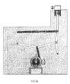
Figure 1 is a front view of the first power multiplier lever system combination, where we can see the first lever pair is positioned at 90º in relation to the floor; -
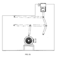
Figure 2 is a front view of the first power multiplier lever system combination, where we can see the first lever pair has started its movement in function of the axle rotation which induces movement in the wheel to which the first lever pair is coupled; -
Figure 3 is a front view of the first power multiplier lever system combination, where we can see the first lever pair continues moving; -
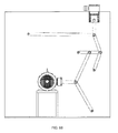
Figure 4 is a perspective view of the first power multiplier lever system combination, where we can see the lever pairs; -
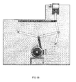
Figure 5 is a front view of a second power multiplier lever system combination, where we can see the first lever pair is positioned at 90º in relation to the floor; -
Figure 6 is a front view of a second power multiplier lever system combination, where we can see the first lever pair has started its movement in function of the axle rotation which induces movement in the wheel to which the first lever pair is coupled; -
Figure 7 is a front view of a second power multiplier lever system combination, where we can see the first lever pair continues moving; -
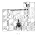
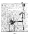
Figure 8 is a front view of a third power multiplier lever system combination, where we can see the first lever pair is positioned at 0° in relation to the floor; -
Figure 9 is a front view of a third power multiplier lever system combination, where we can see the first lever pair has started its movement in function of the axle rotation which induces movement in the wheel to which the first lever pair is coupled; -
Figure 10 is a front view of a third power multiplier lever system combination, where we can see the first lever pair continues moving; - A power multiplier lever system having a power multiplier lever system that provides an increase of mechanical power generated by the motor, thereby giving greater power to the piston, which makes air compression possible without needing to use a large quantity of mechanical power, comprised by levers, wheels, connectors and pistons. The wheels and levers are positioned at distinct angles which operate as a power multiplier when activated. The axle power/torque is multiplied from the power generating source due to the angles made by the levers position. Two wheels are connected directly to the motor axle and are also connected to the first levers. The last pair o levers is connected to the pistons.
- The power multiplier lever system can have the selected combination of a system consist of 7 lever pairs where the first is connected to the wheels that are directly coupled to the motor axle. The first pair of levers is connected to the wheels in opposite positions.
- The power multiplier lever system can have the selected combination of a system consist of 6 lever pairs, where the first pair is connected to the wheels that are coupled directly to the motor axle.
- The power multiplier lever system can have the selected combination of a system consist of 8 lever pairs, where the first pair is connected to the wheels that are coupled directly to the motor axle.
- The power multiplier lever system can have the selected combination of a system comprises of 7 lever pairs where the first is connected to the wheels that are directly coupled to the motor axle.
- The power multiplier lever system can have the selected combination of a system comprises of 6 lever pairs where the first is connected to the wheels that are directly coupled to the motor axle.
- The power multiplier lever system can have the selected combination of a system comprises of 8 lever pairs where the first is connected to the wheels that are directly coupled to the motor axle.
- The power multiplier lever system causes the axle power/torque to be multiplied from the power generating source due to the angles made by the levers position. These angles the consequence of the position of the levers are defined in function of the objective for which it will be used.
- Two wheels are directly connected to the motor axle; these wheels are connected to the first levers. Afterward we have a sequence of lever pairs which will depend on our final objective. The last lever pair will be connected to the pistons.
- In the first selected combination (it can be seen in
Figures 1 to 4 ), there is a lever system with 7 lever pairs where the first lever pair is connected to the wheels that are coupled directly to the motor axle. This first lever pair is connected to the wheels in opposite positions, in other words, when the wheels are stationary in their starting position one lever of the pair is positioned at a point of this wheels and the other lever of the same pair is positioned at exactly 180° from this point. - At the opposite end of the one fixed to the wheel we fix another lever and so on and the last lever pair will couple to the pistons.
- In a second selected combination (it can be seen in
Figures 5 to 7 ), there is a lever system with 6 lever pairs where the first lever pair is connected to the wheels that are coupled directly to the motor axle. This first lever pair is connected to the wheels in opposite positions, in other words, when the wheels are stationary in their starting position one lever of the pair is positioned at a point of this wheels and the other lever of the same pair is positioned at exactly 180° from this point. - At the opposite end of the one fixed to the wheel we fix another lever and so on and the last lever pair will couple to the pistons.
- In a third selected combination (it can be seen in
Figures 8 to 10 ), there is a lever system with 8 lever pairs where the first lever pair is connected to the wheels that are coupled directly to the motor axle. This first lever pair is connected to the wheels in opposite positions, in other words, when the wheels are stationary in their starting position one lever of the pair is positioned at a point of this wheels and the other lever of the same pair is positioned at exactly 180° from this point. - At the opposite end of the one fixed to the wheel we fix another lever and so on and the last lever pair will couple to the pistons.
- Therefore this disclosure resolves a problem that has impeded the greater use of air compressors in industry, the high relative cost of power use.
- It should be evident to technical experts that this disclosure can be configured in many other specific forms without leaving the spirit or scope of the disclosure. In particular, it should be understood that the disclosure can be configured in the described forms.
- Therefore the examples and configurations presented should be considered illustrative and not restrictive and the disclosure should not be limited to the details supplied in this document, but can be modified inside the scope and equivalence of the attached claims.
Claims (13)
- "POWER MULTIPLIER LEVER SYSTEM", CHARACTERIZED by having a power multiplier lever system that provides an increase of mechanical power generated by the motor, thereby giving greater power to the piston, which makes air compression possible without needing to use a large quantity of mechanical power, comprised by levers, wheels, connectors and pistons.
- "POWER MULTIPLIER LEVER SYSTEM", in accordance with claim 1, CHARACTERIZED by the wheels and levers being positioned at distinct angles which operate as a power multiplier when activated.
- "POWER MULTIPLIER LEVER SYSTEM", in accordance with claim 1 CHARACTERIZED by the axle power / torque being multiplied from the power generating source due to the angles made by the levers position.
- "POWER MULTIPLIER LEVER SYSTEM", in accordance with claim 1 CHARACTERIZED by two wheels that are connected directly to the motor axle and are also connected to the first levers.
- "POWER MULTIPLIER LEVER SYSTEM", in accordance with 1 CHARACTERIZED by the last pair of levers being connected to the pistons.
- "POWER MULTIPLIER LEVER SYSTEM", in accordance with any one of the above claims CHARACTERIZED by the selected combination of a system consists of 7 lever pairs where the first is connected to the wheels that are directly coupled to the motor axle.
- "POWER MULTIPLIER LEVER SYSTEM", in accordance with claim 6, CHARACTERIZED by the first pair of levers being connected to the wheels in opposite positions.
- "POWDER MULTIPLIER LEVER SYSTEM", in accordance with any one of the above claims CHARACTERIZED by a second selected combination of a lever system consists of 6 lever pairs, where the first pair is connected to the wheels that are coupled directly to the motor axle.
- "POWER MULTIPLIER LEVER SYSTEM", in accordance with any one of the above CHARACTERIZED by a third selected combination of a lever system consists of 8 lever pairs, where the first pair is connected to the wheels that are coupled directly to the motor axle.
- "POWER MULTIPLIER LEVER SYSTEM", in accordance with any one of the above claims CHARACTERIZED BY the selected combination of a system comprises 7 lever pairs where the first is connected to the wheels that are directly coupled to the motor axle.
- "POWDER MULTIPLIER LEVER SYSTEM", in accordance with claim 10, CHARACTERIZED by the first pair of levers being connected to the wheels in opposite positions.
- "POWER MULTIPLIER LEVER SYSTEM", in accordance with any one of the above claims CHARACTERIZED by a second selected combination of a lever system comprises 6 lever pairs, where the first pair is connected to the wheels that are coupled directly to the motor axle.
- "POWER MULTIPLIER LEVER SYSTEM", in accordance with any one of the above claims CHARACTERIZED by a third selected combination of a lever system comprises 8 lever pairs, where the first pair is connected to the wheels that are coupled directly to the motor axle.
Applications Claiming Priority (3)
| Application Number | Priority Date | Filing Date | Title |
|---|---|---|---|
| US23903409P | 2009-09-01 | 2009-09-01 | |
| US12/854,162 US20110209569A1 (en) | 2009-09-01 | 2010-08-10 | Power multiplier lever system |
| PCT/IB2010/053909 WO2011027294A2 (en) | 2009-09-01 | 2010-08-31 | Power multiplier system with levers |
Publications (2)
| Publication Number | Publication Date |
|---|---|
| EP2474738A2 true EP2474738A2 (en) | 2012-07-11 |
| EP2474738A4 EP2474738A4 (en) | 2013-05-22 |
Family
ID=43649719
Family Applications (1)
| Application Number | Title | Priority Date | Filing Date |
|---|---|---|---|
| EP10813412.3A Withdrawn EP2474738A4 (en) | 2009-09-01 | 2010-08-31 | Power multiplier system with levers |
Country Status (10)
| Country | Link |
|---|---|
| US (1) | US20110209569A1 (en) |
| EP (1) | EP2474738A4 (en) |
| JP (1) | JP2013504021A (en) |
| KR (1) | KR20120061907A (en) |
| CN (1) | CN102483048A (en) |
| AU (1) | AU2010290876A1 (en) |
| BR (1) | BR112012004259A2 (en) |
| CA (1) | CA2771873A1 (en) |
| MX (1) | MX2012002607A (en) |
| WO (1) | WO2011027294A2 (en) |
Families Citing this family (3)
| Publication number | Priority date | Publication date | Assignee | Title |
|---|---|---|---|---|
| WO2017000077A1 (en) * | 2015-06-29 | 2017-01-05 | Navea Lucar Juan Lester | Force amplifier |
| CN108775388B (en) * | 2018-08-29 | 2023-06-16 | 蔡兆昶 | Duplex lever synchronous rotation reinforcement transmission case |
| JPWO2023163222A1 (en) * | 2022-02-28 | 2023-08-31 |
Family Cites Families (26)
| Publication number | Priority date | Publication date | Assignee | Title |
|---|---|---|---|---|
| US4113065A (en) * | 1975-07-08 | 1978-09-12 | Robert Staines | Scissors lift |
| US4151758A (en) * | 1977-08-01 | 1979-05-01 | Natalie Adam J | Power multiplier |
| US4194723A (en) * | 1978-04-14 | 1980-03-25 | Jlg Industries, Inc. | Scissors linkage workman's platform |
| BR8302216A (en) | 1983-04-29 | 1984-12-04 | Jose Aparecido De Souza | POWER MULTIPLICATOR WITH ROTATION SPEED MAINTENANCE |
| DE3640136A1 (en) * | 1986-11-25 | 1988-06-01 | Helmut Juengling | Compression device |
| BR8702053A (en) * | 1987-04-06 | 1988-11-01 | Osvaldo Dela Coleta | LEVER ENGINE |
| JP2605333B2 (en) | 1988-03-17 | 1997-04-30 | 松下電器産業株式会社 | Ultrasonic motor drive |
| IT1235432B (en) * | 1988-11-16 | 1992-07-10 | Sarno Cosimo | FOUR-POINT DEAD POINT CRANK |
| US5295898A (en) * | 1992-12-22 | 1994-03-22 | Acraloc Corporation | Loin puller |
| DE4317226A1 (en) * | 1993-05-24 | 1994-12-01 | Schweizer Viktor Dipl Ing Fh | Con rod-guided engine |
| BR9502446A (en) | 1995-08-02 | 1997-08-26 | Marcelo Luiz Sarti | Engine power multiplier |
| US5901270A (en) * | 1996-09-12 | 1999-05-04 | The Plastic Forming Company, Inc. | Apparatus for hot fluid trimming of plastic molded articles |
| CH695832A5 (en) * | 1997-08-22 | 2006-09-15 | Istvan Simon | Hydraulic drive. |
| US6241057B1 (en) * | 1998-12-03 | 2001-06-05 | Westinghouse Air Brake Company | Hydraulic parking brake lever arrangement for a railroad vehicle braking system |
| FR2791737B1 (en) * | 1999-03-31 | 2002-02-15 | Sorelec | EXHAUST PUMP |
| DE19918700A1 (en) * | 1999-04-26 | 2000-11-02 | Mueller Weingarten Maschf | Hydromechanical press drive |
| ITPZ990003A1 (en) * | 1999-07-02 | 2001-01-02 | Cosimo Sarno | ISOMETRIC COMBUSTION SYSTEMS. |
| US6702805B1 (en) * | 1999-11-12 | 2004-03-09 | Microdexterity Systems, Inc. | Manipulator |
| GR1003523B (en) * | 2000-04-21 | 2001-01-22 | Αλεξανδρου Παναγιωτης Γεωργιου | Engines with multipliers |
| US6419454B1 (en) | 2000-06-14 | 2002-07-16 | Leo P. Christiansen | Air compressor control sequencer |
| US6688147B2 (en) * | 2000-06-19 | 2004-02-10 | Ceilings Plus, Inc. | Panel curving machine |
| BR0201322A (en) | 2002-04-01 | 2003-12-16 | Alexandre Hideki Freita Sonobe | Force multiplier |
| CA2398132C (en) * | 2002-08-13 | 2011-07-19 | Romain Julien | Mobile elevator working and load-lifting platform |
| US6809426B2 (en) * | 2003-01-06 | 2004-10-26 | Claude A. Naar | Gravity-based vehicle power system |
| DE202004000470U1 (en) * | 2004-01-14 | 2004-05-06 | Schönherr, Sabina | Vehicle's continuously variable transmission has compressor which directs force via piston, connecting rod and adjusting device upon one-sided lever arm rotatably mounted by one side on fixed point |
| BRPI0702406A2 (en) * | 2007-07-11 | 2009-02-25 | Montini Consuelo Soares | force multiplier by leverage |
-
2010
- 2010-08-10 US US12/854,162 patent/US20110209569A1/en not_active Abandoned
- 2010-08-31 WO PCT/IB2010/053909 patent/WO2011027294A2/en not_active Ceased
- 2010-08-31 BR BR112012004259A patent/BR112012004259A2/en not_active IP Right Cessation
- 2010-08-31 MX MX2012002607A patent/MX2012002607A/en not_active Application Discontinuation
- 2010-08-31 CN CN2010800395063A patent/CN102483048A/en active Pending
- 2010-08-31 CA CA2771873A patent/CA2771873A1/en not_active Abandoned
- 2010-08-31 AU AU2010290876A patent/AU2010290876A1/en not_active Abandoned
- 2010-08-31 KR KR1020127007296A patent/KR20120061907A/en not_active Withdrawn
- 2010-08-31 EP EP10813412.3A patent/EP2474738A4/en not_active Withdrawn
- 2010-08-31 JP JP2012527434A patent/JP2013504021A/en active Pending
Also Published As
| Publication number | Publication date |
|---|---|
| US20110209569A1 (en) | 2011-09-01 |
| BR112012004259A2 (en) | 2016-02-16 |
| AU2010290876A1 (en) | 2012-04-26 |
| JP2013504021A (en) | 2013-02-04 |
| EP2474738A4 (en) | 2013-05-22 |
| MX2012002607A (en) | 2012-04-02 |
| WO2011027294A2 (en) | 2011-03-10 |
| KR20120061907A (en) | 2012-06-13 |
| WO2011027294A3 (en) | 2011-11-10 |
| CN102483048A (en) | 2012-05-30 |
| CA2771873A1 (en) | 2011-03-10 |
Similar Documents
| Publication | Publication Date | Title |
|---|---|---|
| US20170067454A1 (en) | Compressed air energy storage system | |
| CN204921281U (en) | Dual output positive displacement high pressure boiler water -feeding pump | |
| EP2474738A2 (en) | Power multiplier system with levers | |
| CN201494971U (en) | Hydraulic type mechanical expansion and contraction shaft | |
| CN101860117B (en) | High-speed motor and assembly method thereof | |
| CN202646434U (en) | Power transmission coupler capable of realizing rapid meshing | |
| CN204113553U (en) | A kind of rise-fall type generator set | |
| CN2775362Y (en) | Energy storage type fluid pressure forming device | |
| CN105020117A (en) | Multi-star symmetric oilless compressor | |
| CN204877828U (en) | Magnetic force hydropneumatic engine | |
| CN200947582Y (en) | A kind of motor soft start device | |
| CN202292612U (en) | Wheel remover capable of detaching coupler | |
| CN2623366Y (en) | Driving force device of card punchs | |
| CN101278123A (en) | Compressor unit comprising an eccentric gear | |
| CN106368922A (en) | Single-output volumetric water feed pump for high-pressure boiler | |
| CN202152720U (en) | Four-stage compressor for household gas | |
| CN201292030Y (en) | U type punched card machine of pedal | |
| CN204545865U (en) | A kind of bulldozer final drive boss pressing machine | |
| CN204921280U (en) | Single -output positive displacement high pressure boiler water -feeding pump | |
| US20200378349A1 (en) | Drive of a pump | |
| CN2577092Y (en) | Lubricating oil feeding apparatus | |
| CN202580548U (en) | Electric oiler | |
| CN102528510A (en) | Center processor broaching tool drive hydraulic cylinder oil supply mechanism | |
| CN201744544U (en) | Novel small-sized manual and motor-driven punch press | |
| CN106230184A (en) | A kind of ratchet variable speed electric motors, particularly |
Legal Events
| Date | Code | Title | Description |
|---|---|---|---|
| PUAI | Public reference made under article 153(3) epc to a published international application that has entered the european phase |
Free format text: ORIGINAL CODE: 0009012 |
|
| 17P | Request for examination filed |
Effective date: 20120329 |
|
| AK | Designated contracting states |
Kind code of ref document: A2 Designated state(s): AL AT BE BG CH CY CZ DE DK EE ES FI FR GB GR HR HU IE IS IT LI LT LU LV MC MK MT NL NO PL PT RO SE SI SK SM TR |
|
| DAX | Request for extension of the european patent (deleted) | ||
| A4 | Supplementary search report drawn up and despatched |
Effective date: 20130423 |
|
| RIC1 | Information provided on ipc code assigned before grant |
Ipc: F04B 9/02 20060101ALI20130417BHEP Ipc: F04B 53/14 20060101ALI20130417BHEP Ipc: F16H 21/32 20060101AFI20130417BHEP Ipc: F04B 35/01 20060101ALI20130417BHEP |
|
| STAA | Information on the status of an ep patent application or granted ep patent |
Free format text: STATUS: THE APPLICATION IS DEEMED TO BE WITHDRAWN |
|
| 18D | Application deemed to be withdrawn |
Effective date: 20131126 |