EP2474442A1 - Subsystem for seat weight detection - Google Patents
Subsystem for seat weight detection Download PDFInfo
- Publication number
- EP2474442A1 EP2474442A1 EP10812084A EP10812084A EP2474442A1 EP 2474442 A1 EP2474442 A1 EP 2474442A1 EP 10812084 A EP10812084 A EP 10812084A EP 10812084 A EP10812084 A EP 10812084A EP 2474442 A1 EP2474442 A1 EP 2474442A1
- Authority
- EP
- European Patent Office
- Prior art keywords
- seat
- weight detecting
- ecu
- fpc
- functional portion
- Prior art date
- Legal status (The legal status is an assumption and is not a legal conclusion. Google has not performed a legal analysis and makes no representation as to the accuracy of the status listed.)
- Granted
Links
Images


Classifications
-
- B—PERFORMING OPERATIONS; TRANSPORTING
- B60—VEHICLES IN GENERAL
- B60R—VEHICLES, VEHICLE FITTINGS, OR VEHICLE PARTS, NOT OTHERWISE PROVIDED FOR
- B60R21/00—Arrangements or fittings on vehicles for protecting or preventing injuries to occupants or pedestrians in case of accidents or other traffic risks
- B60R21/01—Electrical circuits for triggering passive safety arrangements, e.g. airbags, safety belt tighteners, in case of vehicle accidents or impending vehicle accidents
- B60R21/015—Electrical circuits for triggering passive safety arrangements, e.g. airbags, safety belt tighteners, in case of vehicle accidents or impending vehicle accidents including means for detecting the presence or position of passengers, passenger seats or child seats, and the related safety parameters therefor, e.g. speed or timing of airbag inflation in relation to occupant position or seat belt use
-
- G—PHYSICS
- G01—MEASURING; TESTING
- G01G—WEIGHING
- G01G19/00—Weighing apparatus or methods adapted for special purposes not provided for in the preceding groups
- G01G19/40—Weighing apparatus or methods adapted for special purposes not provided for in the preceding groups with provisions for indicating, recording, or computing price or other quantities dependent on the weight
- G01G19/413—Weighing apparatus or methods adapted for special purposes not provided for in the preceding groups with provisions for indicating, recording, or computing price or other quantities dependent on the weight using electromechanical or electronic computing means
- G01G19/414—Weighing apparatus or methods adapted for special purposes not provided for in the preceding groups with provisions for indicating, recording, or computing price or other quantities dependent on the weight using electromechanical or electronic computing means using electronic computing means only
- G01G19/4142—Weighing apparatus or methods adapted for special purposes not provided for in the preceding groups with provisions for indicating, recording, or computing price or other quantities dependent on the weight using electromechanical or electronic computing means using electronic computing means only for controlling activation of safety devices, e.g. airbag systems
-
- B—PERFORMING OPERATIONS; TRANSPORTING
- B60—VEHICLES IN GENERAL
- B60N—SEATS SPECIALLY ADAPTED FOR VEHICLES; VEHICLE PASSENGER ACCOMMODATION NOT OTHERWISE PROVIDED FOR
- B60N2/00—Seats specially adapted for vehicles; Arrangement or mounting of seats in vehicles
- B60N2/002—Seats provided with an occupancy detection means mounted therein or thereon
- B60N2/0021—Seats provided with an occupancy detection means mounted therein or thereon characterised by the type of sensor or measurement
- B60N2/0024—Seats provided with an occupancy detection means mounted therein or thereon characterised by the type of sensor or measurement for identifying, categorising or investigation of the occupant or object on the seat
- B60N2/0025—Seats provided with an occupancy detection means mounted therein or thereon characterised by the type of sensor or measurement for identifying, categorising or investigation of the occupant or object on the seat by using weight measurement
-
- B—PERFORMING OPERATIONS; TRANSPORTING
- B60—VEHICLES IN GENERAL
- B60N—SEATS SPECIALLY ADAPTED FOR VEHICLES; VEHICLE PASSENGER ACCOMMODATION NOT OTHERWISE PROVIDED FOR
- B60N2/00—Seats specially adapted for vehicles; Arrangement or mounting of seats in vehicles
- B60N2/002—Seats provided with an occupancy detection means mounted therein or thereon
- B60N2/0021—Seats provided with an occupancy detection means mounted therein or thereon characterised by the type of sensor or measurement
- B60N2/0035—Seats provided with an occupancy detection means mounted therein or thereon characterised by the type of sensor or measurement characterised by the sensor data transmission, e.g. wired connections or wireless transmitters therefor; characterised by the sensor data processing, e.g. seat sensor signal amplification or electric circuits for providing seat sensor information
-
- B—PERFORMING OPERATIONS; TRANSPORTING
- B60—VEHICLES IN GENERAL
- B60R—VEHICLES, VEHICLE FITTINGS, OR VEHICLE PARTS, NOT OTHERWISE PROVIDED FOR
- B60R21/00—Arrangements or fittings on vehicles for protecting or preventing injuries to occupants or pedestrians in case of accidents or other traffic risks
- B60R21/01—Electrical circuits for triggering passive safety arrangements, e.g. airbags, safety belt tighteners, in case of vehicle accidents or impending vehicle accidents
- B60R21/015—Electrical circuits for triggering passive safety arrangements, e.g. airbags, safety belt tighteners, in case of vehicle accidents or impending vehicle accidents including means for detecting the presence or position of passengers, passenger seats or child seats, and the related safety parameters therefor, e.g. speed or timing of airbag inflation in relation to occupant position or seat belt use
- B60R21/01512—Passenger detection systems
- B60R21/01516—Passenger detection systems using force or pressure sensing means
- B60R21/0152—Passenger detection systems using force or pressure sensing means using strain gauges
-
- B—PERFORMING OPERATIONS; TRANSPORTING
- B60—VEHICLES IN GENERAL
- B60N—SEATS SPECIALLY ADAPTED FOR VEHICLES; VEHICLE PASSENGER ACCOMMODATION NOT OTHERWISE PROVIDED FOR
- B60N2210/00—Sensor types, e.g. for passenger detection systems or for controlling seats
- B60N2210/40—Force or pressure sensors
- B60N2210/42—Strain gauges
-
- B—PERFORMING OPERATIONS; TRANSPORTING
- B60—VEHICLES IN GENERAL
- B60N—SEATS SPECIALLY ADAPTED FOR VEHICLES; VEHICLE PASSENGER ACCOMMODATION NOT OTHERWISE PROVIDED FOR
- B60N2220/00—Computerised treatment of data for controlling of seats
- B60N2220/20—Computerised treatment of data for controlling of seats using a deterministic algorithm
Definitions
- the present invention relates to a seat weight detecting subsystem, which is provided for each seat mounted inside a vehicle and having a plurality of weight detecting sensors, and outputs weight detection data which is necessary for processing operations of an ECU (Electronic Control Unit) of a main system.
- ECU Electronic Control Unit
- Those systems include, for example, a system for determining whether an occupant seated on a seat is an adult based on the weight of the occupant, and a system that enables the actuation of an air bag or the retention of a seat belt to be satisfactorily performed based on the weight of the occupant seated on the seat.
- a system disclosed in the below-mentioned patent document 1 has weight detecting sensors respectively provided at four supporting leg portions that support a vehicle seat, an electronic control unit which includes a determining circuit that determines whether or not an occupant is an adult based on the signals from the weight detecting sensors, and an air bag electronic control unit which is connected to the electronic control unit.
- the weight detecting sensors and the electronic control unit are connected by a wire harness which is configured by a predetermined number of electric wires. Since four weight detecting sensors are provided for each seat, many wire harnesses (electric wires) are connected to the electronic control unit.
- the object of the invention is to provide a seat weight detecting subsystem that makes it possible to improve assembly efficiency and save the space allotted to the wires.
- a seat weight detecting subsystem provided for each seat in a vehicle and for outputting weight detection data which is necessary for a processing operation of an ECU in a main system, the seat weight detecting subsystem comprising:
- the seat side ECU functional portion includes: a plurality of first ECU functional portions provided as many as the number of the plurality of weight detecting sensors; and a second ECU functional portion connected to the plurality of first ECU functional portions through a common circuit in the FPC.
- the signal receiving section includes: a second signal receiving section provided in the second ECU functional portion; and first signal receiving sections which are respectively provided in the plurality of first ECU functional portions and output the received sensor signals to the second signal receiving section through the common circuit while associating the received sensor signals to the weight detecting sensors at the corresponding arrangements.
- the first ECU functional portion includes the sensor connecting sections and the first signal receiving section.
- the second ECU functional portion includes the second signal receiving section, the data generating section and the data outputting section.
- the FPC includes the common circuit.
- the main system includes a plurality of seat weight detecting subsystems, and the weight detection data for each of the seats are gathered in the ECU of the main system by the seat weight detecting subsystems.
- the ECU of the main system executes specified processing operations based on the weight detection data. The result of the processing operations is used, for example, when an air bag is actuated.
- the seat weight detecting subsystem includes the power supplying member, and the functions of the ECU that are exclusive to the seat are added to the power supplying member.
- the power supplying member includes the seat side ECU functional portion which has the functions of the ECU that are exclusive to the seat, and the FPC (Flexible Printed Circuits) whose size corresponds to all the plurality of weight detecting sensors, and integrates the seat side ECU functional portion and the FPC by mounting the seat side ECU functional portion to the FPC.
- the assembly operation of the seat weight detecting subsystem is completed. Since the power supplying member has the FPC, the seat weight detecting subsystem becomes thinner. In the present invention, if the FPC is configured to have the common circuit, the number of circuits in the FPC becomes less. Therefore, the seat weight detecting subsystem becomes thinner and narrower.
- the power supplying member is included in the configuration of the system by mounting the seat side ECU functional portion to the FPC, the effect of improving the assembly efficiency and saving wire allotting space can be obtained.
- a seat weight detecting subsystem includes a power supplying member, and the functions of an ECU that are exclusive to a seat are added to the power supplying member.
- the power supplying member has a FPC, and a seat side ECU functional portion is provided on a specified position in a circuit of the FPC.
- Fig. 1 is a schematic diagram of a whole system which includes the seat weight detecting subsystems of the present invention.
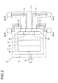
- Fig. 2 is a schematic block diagram of the seat weight detecting subsystem of Fig. 1 .
- a main system indicated as the reference number 1 is, for example, a system related to control of an air bag 2.
- the main system includes an ECU (Electronic Control Unit) 3 for controlling the air bag 2 and a plurality of seat weight detecting subsystems 4 which are connected to the ECU 3.
- the seat weight detecting subsystem 4 is configured to be able to output weight detection data which is necessary for the processing operation of the ECU3.
- the reference number 5 indicates a power supply which supplies power to the main system 1 and the seat weight detecting subsystems 4.
- the reference number 6 indicates ground.
- the seat weight detecting subsystem 4 is provided for each seat 7 mounted in a vehicle (vehicle seat).
- the seat weight detecting subsystem 4 includes weight detecting sensors 8 which are provided respectively at four supporting leg portions (the illustrations of which are omitted) that support the seat 7, and a power supplying member 9 which is connected to the weight detecting sensors 8, the power supply 5, the ECU 3, etc.
- the seat weight detecting subsystem 4 is configured to be able to detect the weight of an occupant seated on the seat 7.
- the weight detecting sensor 8 is a so-called load sensor which includes a strain detecting element such as a strain gauge.
- the weight detecting sensor 8 is able to electrically detect the deflecting amount of a deflection portion which corresponds to the weight (load) of an occupant on a cushion of the seat 7.
- the reference number 8a indicates a weight detecting sensor that is mounted at a frontal left side
- the reference number 8b indicates a weight detecting sensor that is mounted at a frontal right side
- the reference number 8c indicates a weight detecting sensor that is mounted at a rear left side
- the reference number 8d indicates a weight detecting sensor that is mounted at a rear right side, respectively.
- the seat weight detecting subsystem 4 is characterized in the power supplying member 9 included therein. Below, the power supplying member 9 is described with reference to Figs. 1 and 2 .
- the power supplying member 9 includes a FPC 10 and a seat side ECU functional portion 11 which is integrally mounted to the FPC 10.
- the FPC 10 is a well known member (flexible printed circuit board) that is thin and flexible, and has circuits 12 which form desired routes.
- the FPC 10 is formed to have a size that corresponds to all the four weight detecting sensors 8 provided at the seat 7 (corresponding to the arrangement of the four weight detecting sensors 8).
- Each of the circuits 12 is configured by a power supply line connected to the power supply 5, a GND line connected to the ground 6, and a signal line (communication line), although they are not given specific numbers.
- the FPC 10 is formed so as to aggregate the circuits 12 that relate to the four weight detecting sensors 8.
- the seat side ECU functional portion 11 has ECU functions that are dedicated to the seat 7.
- the seat side ECU functional portion 11 is configured by a micro-computer which has a CPU, a RAM, a ROM, etc.
- the CPU can execute various processing operations in accordance with control programs, original data, etc which are stored beforehand.
- the seat side ECU functional portion 11 has four sensor connecting section 13, a signal receiving section 14, a data generating section 15 and a data outputting section 16.
- the sensor connecting sections 13 are provided as connecting parts that correspond to the weight detecting sensors 8.
- the sensor connecting sections 13 are connected to the weight detecting sensors 8 through the corresponding circuits 12 respectively.
- the connecting ends of the circuits 12 are formed in accordance with the shapes of the connecting parts of the weight detecting sensors 8 (The connecting shape is not particularly limited.
- a connector can be an example of the connection part. It is preferred that the connecting shapes make it possible to easily assemble the power supplying member 9 to the four corresponding weight detecting sensors 8).
- the signal receiving section 14 is provided as a part which receives sensor signals from the weight detecting sensors 8 through the sensor connecting sections 13. In addition, the signal receiving section 14 associates a sensor signal with the weight detecting sensor 8 in such a way that the data generating section 15 can grasp the sensor signal is output from which weight detecting sensor 8, and has the function to transfer the sensor signal to the data generating section 15.
- the data generating section 15 is provided as a part that generates weight detection data, which is necessary for the processing operation of the ECU 3, based on the received sensor signals (The data structure of the weight detection data depends on the ECU 3 and its description is omitted here).
- the data outputting section 16 is provided as a part that outputs the weight detection data generated in the data generating section 15 to the ECU 3.
- the data outputting section 16 is connected to the ECU 3 through the corresponding circuit 12.
- the present invention has a configuration in which the connections related to the four weight detecting sensors 8 and their circuits 12 are aggregated into the FPC 10 of the power supplying member 9 in the structure. Therefore, the working efficiency is improved significantly when compared with the prior art. In addition, since the FPC 10 is included in the structure, the space-saving which relates to wire allotment is obtained. In addition, since the seat side ECU functional portion 11 is mounted to the FPC 10, the working efficiency is improved when compared with assembling them individually. In addition, since the seat side ECU functional portion 11 is mounted to the FPC 10, the number of articles in the assembly of the seat 7 is also reduced when compared with the prior art.
- the main system 1 is a system which relates to the control of an air bag 2 in the above description, it is not limited thereto.
- it may also be a system that enables the retention of a seat belt to be performed satisfactorily based on the weight of an occupant seated on the seat 7.
- Fig. 3 is a schematic block diagram which shows a seat weight detecting subsystem of the present invention. Furthermore, the components that are identical with those in the above-mentioned first embodiment are illustrated as identical numbers, and their detailed description is omitted.
- a seat weight detecting subsystem 21 is a system that can be replaced with the seat weight detecting subsystem 4 of Embodiment 1, and includes four weight detecting sensors 8 and a power supplying member 22 which is connected to the weight detecting sensors 8, a power supply 5, an ECU 3, etc (See Fig. 1 ).
- the seat weight detecting subsystem 21 is configured to be able to detect the weight of an occupant seated on the seat 7 (See Fig. 1 ).
- the power supplying member 22 includes a FPC 23 and a seat side ECU functional portion 24 which is integrally mounted to the FPC 23.
- the FPC 23 is a well known member (flexible printed circuit board) that is thin and flexible, and has a circuit which forms common, desired routes (common circuit 25).
- the FPC 23 is formed as a shape that corresponds to all the four weight detecting sensors 8 (formed so as to correspond to the arrangement of the four weight detecting sensors 8, and have an exactly traversable circuit shape).
- the common circuit 25 is configured by a power supply line which is connected to the power supply 5 (See Fig. 1 ), a GND line which is connected to the ground 6 (See Fig. 1 ), and a signal line (communication line), although they are not given specific numbers.
- the FPC 23 is formed by aggregating the circuits that relate to the four weight detecting sensors 8 to the common circuit 25.
- the seat side ECU functional portion 24, different from Embodiment 1, includes four first ECU functional portions 24a provided accordingly at four weight detecting sensors 8, and a second ECU functional portion 24b which is connected to the four first ECU functional portions 24a through the common circuit 25 in the FPC 23.
- the seat side ECU functional portion 24 is configured so as to scatter the functions of the seat side ECU functional portion 11 of Embodiment 1.
- the first ECU functional portion 24a has a sensor connecting section 13 and a first signal receiving section 14a described later.
- the second ECU functional portion 24b has a second signal receiving section 14b described later, a data generating section 15, and a data outputting section 16.
- the first signal receiving section 14a of the first ECU functional portion 24a and the second signal receiving section 14b of the second ECU functional portion 24b are portions that correspond to the signal receiving section 14 of Embodiment 1.
- the first signal receiving section 14a and the second signal receiving section 14b associates a sensor signal with the weight detecting sensor 8 in such a way that the data generating section 15 can grasp the sensor signal is output from which weight detecting sensor, and has the function to transfer the sensor signal to the data generating section 15.
- the present invention has a configuration in which the connections related to the four weight detecting sensors 8 and their circuits are aggregated into the FPC 23 of the power supplying member 22 by using the common circuit 25 in the structure. Therefore, similar to Embodiment 1, the working efficiency is improved significantly when compared with the prior art. In addition, since the FPC 23 is included in the structure, the space-saving which relates to wire allotment is obtained. Further, since the second ECU functional portion 24b and the four first ECU functional portions 24a are mounted to the FPC 23 so that they are integrated, the impact of the component number of the seat side ECU functional portions 24 on the working efficiency is eliminated.
- the invention is not limited to the above description, but it is also possible to integrate the weight detecting sensors 8 and the FPC 10 (FPC 23) by mounting the weight detecting sensors 8 to the FPC 10 (FPC 23).
Landscapes
- Engineering & Computer Science (AREA)
- Physics & Mathematics (AREA)
- Mechanical Engineering (AREA)
- Mathematical Physics (AREA)
- Theoretical Computer Science (AREA)
- Aviation & Aerospace Engineering (AREA)
- Transportation (AREA)
- General Physics & Mathematics (AREA)
- Computer Networks & Wireless Communication (AREA)
- Seats For Vehicles (AREA)
- Air Bags (AREA)
Abstract
Description
- The present invention relates to a seat weight detecting subsystem, which is provided for each seat mounted inside a vehicle and having a plurality of weight detecting sensors, and outputs weight detection data which is necessary for processing operations of an ECU (Electronic Control Unit) of a main system.
- Recently, in order to improve the safety of vehicle occupants, many systems have been proposed. Those systems include, for example, a system for determining whether an occupant seated on a seat is an adult based on the weight of the occupant, and a system that enables the actuation of an air bag or the retention of a seat belt to be satisfactorily performed based on the weight of the occupant seated on the seat.
- For example, a system disclosed in the below-mentioned
patent document 1 has weight detecting sensors respectively provided at four supporting leg portions that support a vehicle seat, an electronic control unit which includes a determining circuit that determines whether or not an occupant is an adult based on the signals from the weight detecting sensors, and an air bag electronic control unit which is connected to the electronic control unit. The weight detecting sensors and the electronic control unit are connected by a wire harness which is configured by a predetermined number of electric wires. Since four weight detecting sensors are provided for each seat, many wire harnesses (electric wires) are connected to the electronic control unit. -
-
Patent Document 1JP Patent Document No. 2006-256597 - However, in the above prior art, since a large number of wire harnesses are connected, and the number of electric wires also increases, the working man-hours for each seat adversely increase. As a result, there are such problems as influences on cost and working efficiency. In addition, since the number of electric wires increases, which makes the electric wires thicker, it is a problem to ensure that enough space inside the seat and the like is allocated to the wires.
- In view of the above-mentioned problems, the object of the invention is to provide a seat weight detecting subsystem that makes it possible to improve assembly efficiency and save the space allotted to the wires.
- In order to achieve the above object, according to the present invention, there is provided a seat weight detecting subsystem provided for each seat in a vehicle and for outputting weight detection data which is necessary for a processing operation of an ECU in a main system, the seat weight detecting subsystem comprising:
- a plurality of weight detecting sensors; and
- a power supplying member that is connected to a power supply,
- wherein the power supplying member includes:
- a FPC which has circuits forming desired routes, and is formed so as to have a size which corresponds to at least arrangements of all of the plurality of weight detecting sensors on the seat in the vehicle; and
- a seat side ECU functional portion having:
- sensor connecting sections which serve as connecting portions of the plurality of weight detecting sensors at the corresponding arrangements;
- a signal receiving section which receives sensor signals from the weight detecting sensors through the sensor connecting sections;
- a data generating section which generates the weight detection data based on the received sensor signals; and
- a data outputting section as a portion which outputs the generated weight detection data to the ECU; and
- wherein the seat side ECU functional portion is mounted to a specified position on the circuits of the FPC.
- Also, in the above described seat weight detecting subsystem, the seat side ECU functional portion includes: a plurality of first ECU functional portions provided as many as the number of the plurality of weight detecting sensors; and a second ECU functional portion connected to the plurality of first ECU functional portions through a common circuit in the FPC. The signal receiving section includes: a second signal receiving section provided in the second ECU functional portion; and first signal receiving sections which are respectively provided in the plurality of first ECU functional portions and output the received sensor signals to the second signal receiving section through the common circuit while associating the received sensor signals to the weight detecting sensors at the corresponding arrangements. The first ECU functional portion includes the sensor connecting sections and the first signal receiving section. The second ECU functional portion includes the second signal receiving section, the data generating section and the data outputting section. The FPC includes the common circuit.
- According to the present invention characterized in above features, the main system includes a plurality of seat weight detecting subsystems, and the weight detection data for each of the seats are gathered in the ECU of the main system by the seat weight detecting subsystems. The ECU of the main system executes specified processing operations based on the weight detection data. The result of the processing operations is used, for example, when an air bag is actuated. The seat weight detecting subsystem includes the power supplying member, and the functions of the ECU that are exclusive to the seat are added to the power supplying member. The power supplying member includes the seat side ECU functional portion which has the functions of the ECU that are exclusive to the seat, and the FPC (Flexible Printed Circuits) whose size corresponds to all the plurality of weight detecting sensors, and integrates the seat side ECU functional portion and the FPC by mounting the seat side ECU functional portion to the FPC. According to this invention, by assembling the power supplying member to the plurality of weight detecting sensors, the assembly operation of the seat weight detecting subsystem is completed. Since the power supplying member has the FPC, the seat weight detecting subsystem becomes thinner. In the present invention, if the FPC is configured to have the common circuit, the number of circuits in the FPC becomes less. Therefore, the seat weight detecting subsystem becomes thinner and narrower.
- According to the present invention, since the power supplying member is included in the configuration of the system by mounting the seat side ECU functional portion to the FPC, the effect of improving the assembly efficiency and saving wire allotting space can be obtained.
- In addition, according to the present invention, by means of the configuration of the seat side ECU functional portion and the configuration of the FPC, the effect of further saving space can be obtained.
-
- [
Fig. 1] Fig. 1 is a schematic diagram of a whole system which includes a seat weight detecting subsystems of the present invention (Embodiment 1). - [
Fig. 2] Fig. 2 is a schematic block diagram of the seat weight detecting subsystem ofFig. 1 . - [
Fig. 3] Fig. 3 is a schematic diagram of seat weight detecting subsystems (Embodiment 2). - A seat weight detecting subsystem includes a power supplying member, and the functions of an ECU that are exclusive to a seat are added to the power supplying member. In particular, the power supplying member has a FPC, and a seat side ECU functional portion is provided on a specified position in a circuit of the FPC.
- Below, the first embodiment will be described with reference to the figures.
Fig. 1 is a schematic diagram of a whole system which includes the seat weight detecting subsystems of the present invention. In addition,Fig. 2 is a schematic block diagram of the seat weight detecting subsystem ofFig. 1 . - In
Fig. 1 , a main system indicated as thereference number 1 is, for example, a system related to control of an air bag 2. The main system includes an ECU (Electronic Control Unit) 3 for controlling the air bag 2 and a plurality of seatweight detecting subsystems 4 which are connected to theECU 3. The seatweight detecting subsystem 4 is configured to be able to output weight detection data which is necessary for the processing operation of the ECU3. Thereference number 5 indicates a power supply which supplies power to themain system 1 and the seatweight detecting subsystems 4. In addition, thereference number 6 indicates ground. - The seat
weight detecting subsystem 4 is provided for eachseat 7 mounted in a vehicle (vehicle seat). The seatweight detecting subsystem 4 includesweight detecting sensors 8 which are provided respectively at four supporting leg portions (the illustrations of which are omitted) that support theseat 7, and apower supplying member 9 which is connected to theweight detecting sensors 8, thepower supply 5, theECU 3, etc. The seatweight detecting subsystem 4 is configured to be able to detect the weight of an occupant seated on theseat 7. - The
weight detecting sensor 8 is a so-called load sensor which includes a strain detecting element such as a strain gauge. Theweight detecting sensor 8 is able to electrically detect the deflecting amount of a deflection portion which corresponds to the weight (load) of an occupant on a cushion of theseat 7. Thereference number 8a indicates a weight detecting sensor that is mounted at a frontal left side, thereference number 8b indicates a weight detecting sensor that is mounted at a frontal right side, thereference number 8c indicates a weight detecting sensor that is mounted at a rear left side, and thereference number 8d indicates a weight detecting sensor that is mounted at a rear right side, respectively. - The seat
weight detecting subsystem 4 is characterized in thepower supplying member 9 included therein. Below, thepower supplying member 9 is described with reference toFigs. 1 and2 . - The
power supplying member 9 includes aFPC 10 and a seat side ECUfunctional portion 11 which is integrally mounted to theFPC 10. TheFPC 10 is a well known member (flexible printed circuit board) that is thin and flexible, and hascircuits 12 which form desired routes. TheFPC 10 is formed to have a size that corresponds to all the fourweight detecting sensors 8 provided at the seat 7 (corresponding to the arrangement of the four weight detecting sensors 8). Each of thecircuits 12 is configured by a power supply line connected to thepower supply 5, a GND line connected to theground 6, and a signal line (communication line), although they are not given specific numbers. TheFPC 10 is formed so as to aggregate thecircuits 12 that relate to the fourweight detecting sensors 8. - The seat side ECU
functional portion 11 has ECU functions that are dedicated to theseat 7. In particular, the seat side ECUfunctional portion 11 is configured by a micro-computer which has a CPU, a RAM, a ROM, etc. The CPU can execute various processing operations in accordance with control programs, original data, etc which are stored beforehand. The seat side ECUfunctional portion 11 has foursensor connecting section 13, asignal receiving section 14, adata generating section 15 and adata outputting section 16. - The
sensor connecting sections 13 are provided as connecting parts that correspond to theweight detecting sensors 8. Thesensor connecting sections 13 are connected to theweight detecting sensors 8 through the correspondingcircuits 12 respectively. Furthermore, the connecting ends of thecircuits 12 are formed in accordance with the shapes of the connecting parts of the weight detecting sensors 8 (The connecting shape is not particularly limited. A connector can be an example of the connection part. It is preferred that the connecting shapes make it possible to easily assemble thepower supplying member 9 to the four corresponding weight detecting sensors 8). - The
signal receiving section 14 is provided as a part which receives sensor signals from theweight detecting sensors 8 through thesensor connecting sections 13. In addition, thesignal receiving section 14 associates a sensor signal with theweight detecting sensor 8 in such a way that thedata generating section 15 can grasp the sensor signal is output from whichweight detecting sensor 8, and has the function to transfer the sensor signal to thedata generating section 15. - The
data generating section 15 is provided as a part that generates weight detection data, which is necessary for the processing operation of theECU 3, based on the received sensor signals (The data structure of the weight detection data depends on theECU 3 and its description is omitted here). Thedata outputting section 16 is provided as a part that outputs the weight detection data generated in thedata generating section 15 to theECU 3. Thedata outputting section 16 is connected to theECU 3 through the correspondingcircuit 12. - In the above-mentioned configuration, once the
power supplying member 9, into which the seat side ECUfunctional portion 11 and theFPC 10 are integrated by mounting the seat side ECUfunctional portion 11 to theFPC 10, is accordingly assembled to the fourweight detecting sensors 8 inside theseat 7, the assembly operation related to the seatweight detecting subsystem 4 is completed. - The present invention has a configuration in which the connections related to the four
weight detecting sensors 8 and theircircuits 12 are aggregated into theFPC 10 of thepower supplying member 9 in the structure. Therefore, the working efficiency is improved significantly when compared with the prior art. In addition, since theFPC 10 is included in the structure, the space-saving which relates to wire allotment is obtained. In addition, since the seat side ECUfunctional portion 11 is mounted to theFPC 10, the working efficiency is improved when compared with assembling them individually. In addition, since the seat side ECUfunctional portion 11 is mounted to theFPC 10, the number of articles in the assembly of theseat 7 is also reduced when compared with the prior art. - Furthermore, although the
main system 1 is a system which relates to the control of an air bag 2 in the above description, it is not limited thereto. For example, it may also be a system that enables the retention of a seat belt to be performed satisfactorily based on the weight of an occupant seated on theseat 7. - Below, a second embodiment will be described with reference to the figures.
Fig. 3 is a schematic block diagram which shows a seat weight detecting subsystem of the present invention. Furthermore, the components that are identical with those in the above-mentioned first embodiment are illustrated as identical numbers, and their detailed description is omitted. - In
Fig. 3 , a seatweight detecting subsystem 21 is a system that can be replaced with the seatweight detecting subsystem 4 ofEmbodiment 1, and includes fourweight detecting sensors 8 and apower supplying member 22 which is connected to theweight detecting sensors 8, apower supply 5, anECU 3, etc (SeeFig. 1 ). The seatweight detecting subsystem 21 is configured to be able to detect the weight of an occupant seated on the seat 7 (SeeFig. 1 ). - The
power supplying member 22 includes aFPC 23 and a seat side ECUfunctional portion 24 which is integrally mounted to theFPC 23. TheFPC 23 is a well known member (flexible printed circuit board) that is thin and flexible, and has a circuit which forms common, desired routes (common circuit 25). TheFPC 23 is formed as a shape that corresponds to all the four weight detecting sensors 8 (formed so as to correspond to the arrangement of the fourweight detecting sensors 8, and have an exactly traversable circuit shape). Thecommon circuit 25 is configured by a power supply line which is connected to the power supply 5 (SeeFig. 1 ), a GND line which is connected to the ground 6 (SeeFig. 1 ), and a signal line (communication line), although they are not given specific numbers. TheFPC 23 is formed by aggregating the circuits that relate to the fourweight detecting sensors 8 to thecommon circuit 25. - The seat side ECU
functional portion 24, different fromEmbodiment 1, includes four first ECUfunctional portions 24a provided accordingly at fourweight detecting sensors 8, and a second ECUfunctional portion 24b which is connected to the four first ECUfunctional portions 24a through thecommon circuit 25 in theFPC 23. - The seat side ECU
functional portion 24 is configured so as to scatter the functions of the seat side ECUfunctional portion 11 ofEmbodiment 1. The first ECUfunctional portion 24a has asensor connecting section 13 and a firstsignal receiving section 14a described later. On the other hand, the second ECUfunctional portion 24b has a secondsignal receiving section 14b described later, adata generating section 15, and adata outputting section 16. - The first
signal receiving section 14a of the first ECUfunctional portion 24a and the secondsignal receiving section 14b of the second ECUfunctional portion 24b are portions that correspond to thesignal receiving section 14 ofEmbodiment 1. The firstsignal receiving section 14a and the secondsignal receiving section 14b associates a sensor signal with theweight detecting sensor 8 in such a way that thedata generating section 15 can grasp the sensor signal is output from which weight detecting sensor, and has the function to transfer the sensor signal to thedata generating section 15. - In the above-mentioned configuration, once the
power supplying member 22, into which the second ECUfunctional portion 24b, the four first ECUfunctional portion 24a and theFPC 23 are integrated by mounting the second ECUfunctional portion 24b and the four first ECUfunctional portion 24a to theFPC 23, is accordingly assembled to the fourweight detecting sensors 8 inside the seat 7 (SeeFig. 1 ), the assembly operation related to the seatweight detecting subsystem 21 is completed. - The present invention has a configuration in which the connections related to the four
weight detecting sensors 8 and their circuits are aggregated into theFPC 23 of thepower supplying member 22 by using thecommon circuit 25 in the structure. Therefore, similar toEmbodiment 1, the working efficiency is improved significantly when compared with the prior art. In addition, since theFPC 23 is included in the structure, the space-saving which relates to wire allotment is obtained. Further, since the second ECUfunctional portion 24b and the four first ECUfunctional portions 24a are mounted to theFPC 23 so that they are integrated, the impact of the component number of the seat side ECUfunctional portions 24 on the working efficiency is eliminated. - In addition, it is apparent that various modifications can be made to the invention without changing the purpose of the invention.
- Furthermore, the invention is not limited to the above description, but it is also possible to integrate the
weight detecting sensors 8 and the FPC 10 (FPC 23) by mounting theweight detecting sensors 8 to the FPC 10 (FPC 23). - Although the present invention is described in detail with reference to the embodiments, it is apparent that various modifications and amendments may be made by those skilled in the art without departing from the spirit and scope of the invention.
- This application is based on the Japanese patent application (patent application No.
2009-199179) filed on August 31, 2009 -
- 1
- main system
- 2
- air bag
- 3
- ECU
- 4
- seat weight detecting subsystem
- 5
- power supply
- 6
- ground
- 7
- seat (vehicle seat)
- 8
- weight detecting sensor
- 9
- power supplying member
- 10
- FPC
- 11
- seat side ECU functional portion
- 12
- circuit
- 13
- sensor connecting section
- 14
- signal receiving section
- 14a
- first signal receiving section
- 14b
- second signal receiving section
- 15
- data generating section
- 16
- data outputting section
- 21
- seat weight detecting subsystem
- 22
- power supplying member
- 23
- FPC
- 24
- seat side ECU functional portion
- 24a
- first ECU functional portion
- 24b
- second ECU functional portion
- 25
- common circuit
Claims (2)
- A seat weight detecting subsystem provided for each seat in a vehicle and for outputting weight detection data which is necessary for a processing operation of an ECU in a main system, the seat weight detecting subsystem comprising:a plurality of weight detecting sensors; anda power supplying member that is connected to a power supply,wherein the power supplying member includes:a FPC which has circuits forming desired routes, and is formed so as to have a size which corresponds to at least arrangements of all of the plurality of weight detecting sensors on the seat in the vehicle; anda seat side ECU functional portion having:sensor connecting sections which serve as connecting portions of the plurality of weight detecting sensors at the corresponding arrangements;a signal receiving section which receives sensor signals from the weight detecting sensors through the sensor connecting sections;a data generating section which generates the weight detection data based on the received sensor signals; anda data outputting section as a portion which outputs the generated weight detection data to the ECU; andwherein the seat side ECU functional portion is mounted to a specified position on the circuits of the FPC.
- The seat weight detecting subsystem according to claim 1, wherein the seat side ECU functional portion includes:a plurality of first ECU functional portions provided as many as the number of the plurality of weight detecting sensors; anda second ECU functional portion connected to the plurality of first ECU functional portions through a common circuit in the FPC;
wherein the signal receiving section includes:a second signal receiving section provided in the second ECU functional portion; andfirst signal receiving sections which are respectively provided in the plurality of first ECU functional portions and output the received sensor signals to the second signal receiving section through the common circuit while associating the received sensor signals to the weight detecting sensors at the corresponding arrangements;
wherein the first ECU functional portion includes the sensor connecting sections and the first signal receiving section;
wherein the second ECU functional portion includes the second signal receiving section, the data generating section and the data outputting section; and
wherein the FPC includes the common circuit.
Applications Claiming Priority (2)
| Application Number | Priority Date | Filing Date | Title |
|---|---|---|---|
| JP2009199179A JP5497376B2 (en) | 2009-08-31 | 2009-08-31 | Seat weight detection subsystem |
| PCT/JP2010/064826 WO2011025038A1 (en) | 2009-08-31 | 2010-08-31 | Subsystem for seat weight detection |
Publications (3)
| Publication Number | Publication Date |
|---|---|
| EP2474442A1 true EP2474442A1 (en) | 2012-07-11 |
| EP2474442A4 EP2474442A4 (en) | 2013-02-27 |
| EP2474442B1 EP2474442B1 (en) | 2014-11-26 |
Family
ID=43628126
Family Applications (1)
| Application Number | Title | Priority Date | Filing Date |
|---|---|---|---|
| EP10812084.1A Not-in-force EP2474442B1 (en) | 2009-08-31 | 2010-08-31 | Subsystem for seat weight detection |
Country Status (5)
| Country | Link |
|---|---|
| US (1) | US8930084B2 (en) |
| EP (1) | EP2474442B1 (en) |
| JP (1) | JP5497376B2 (en) |
| CN (1) | CN102333674B (en) |
| WO (1) | WO2011025038A1 (en) |
Families Citing this family (9)
| Publication number | Priority date | Publication date | Assignee | Title |
|---|---|---|---|---|
| CN103029668A (en) * | 2011-10-10 | 2013-04-10 | 苏州卡泰克电子科技有限公司 | Vehicle occupant type detection device based on film switch technology and use method thereof |
| JP6200250B2 (en) * | 2013-09-18 | 2017-09-20 | 矢崎総業株式会社 | Seat control system and wire harness structure |
| CN105313801B (en) | 2014-05-30 | 2018-01-16 | 矢崎总业株式会社 | Vehicle harness constructs and additional connection member |
| JP6507138B2 (en) * | 2016-10-27 | 2019-04-24 | 矢崎総業株式会社 | Branch structure and wire harness |
| US10553097B2 (en) * | 2017-11-09 | 2020-02-04 | Chukwunoso ARINZE | Interactive smart seat system |
| JP7025188B2 (en) * | 2017-12-04 | 2022-02-24 | 矢崎総業株式会社 | A circuit body for a vehicle and a method for manufacturing a circuit body for a vehicle |
| JP7107669B2 (en) * | 2017-12-04 | 2022-07-27 | 矢崎総業株式会社 | In-vehicle control system and wire harness |
| JP7239264B2 (en) * | 2017-12-04 | 2023-03-14 | 矢崎総業株式会社 | Circuit body for vehicle |
| JP7081944B2 (en) * | 2018-03-07 | 2022-06-07 | 矢崎総業株式会社 | Circuit body for vehicles |
Family Cites Families (22)
| Publication number | Priority date | Publication date | Assignee | Title |
|---|---|---|---|---|
| US4059909A (en) * | 1972-02-09 | 1977-11-29 | The Singer Company | Neural receptor augmented G seat system |
| US5176424A (en) * | 1988-06-10 | 1993-01-05 | Mazda Motor Corporation | Automobile seat assembly |
| US6242701B1 (en) * | 1995-06-07 | 2001-06-05 | Automotive Technologies International, Inc. | Apparatus and method for measuring weight of an occupying item of a seat |
| US7387183B2 (en) * | 1995-06-07 | 2008-06-17 | Automotive Technologies International, Inc. | Weight measuring systems and methods for vehicles |
| US7976060B2 (en) * | 1995-06-07 | 2011-07-12 | Automotive Technologies International, Inc. | Seat load or displacement measuring system for occupant restraint system control |
| EP1318043B1 (en) * | 1999-01-27 | 2009-02-25 | The Furukawa Electric Co., Ltd. | Occupant detecting device |
| JP3521795B2 (en) * | 1999-03-18 | 2004-04-19 | トヨタ自動車株式会社 | Seat detection sensor and airbag device control system for passenger seat using the seat detection sensor |
| EP1063134A1 (en) * | 1999-06-24 | 2000-12-27 | Siemens Aktiengesellschaft | Device for electrically connecting a plurality of sensors integrably fixed on a matrix in a vehicle seat |
| JP3322254B2 (en) * | 1999-10-27 | 2002-09-09 | 日本電気株式会社 | Occupant detection device and occupant detection system |
| US6467361B2 (en) * | 2001-03-20 | 2002-10-22 | Cts Corporation | Strain gage sensor having an unstrained area |
| JP3783925B2 (en) * | 2001-06-20 | 2006-06-07 | 株式会社デンソー | Car occupant protection device |
| JP4734793B2 (en) * | 2001-07-26 | 2011-07-27 | アイシン精機株式会社 | Seating detection device |
| US7255015B2 (en) * | 2003-07-31 | 2007-08-14 | Sensata Technologies, Inc. | Occupant weight sensor for vehicular seats, method for making and system therefor |
| US6932382B2 (en) * | 2003-10-28 | 2005-08-23 | Fci Americas Technology, Inc. | Hall effect sensor assembly |
| DE10354602A1 (en) * | 2003-11-21 | 2005-06-16 | Robert Bosch Gmbh | Connecting elements, methods for bus communication between a control device for controlling personal protection devices as a master and at least one connection element for weight measurement in a seat as a slave and bus system |
| WO2005092193A1 (en) * | 2004-03-25 | 2005-10-06 | Delta Tooling Co., Ltd. | Load body state judgment device, vehicle seat, and computer program |
| JP2006098257A (en) * | 2004-09-30 | 2006-04-13 | Denso Corp | Sensing member, load sensor and occupant detection device |
| JP4878145B2 (en) | 2005-02-16 | 2012-02-15 | カルソニックカンセイ株式会社 | Vehicle occupant detection device |
| US20060185446A1 (en) * | 2005-02-18 | 2006-08-24 | Speckhart Frank H | Printed strain gage for vehicle seats |
| JP4887260B2 (en) * | 2006-10-31 | 2012-02-29 | アイシン精機株式会社 | Passenger load sensor for vehicle seat |
| DE102007035924A1 (en) * | 2007-07-23 | 2009-01-29 | Bag Bizerba Automotive Gmbh | Sensor system and method for determining the weight and / or position of a seat occupant |
| JP5169291B2 (en) | 2008-02-19 | 2013-03-27 | 富士ゼロックス株式会社 | Document management system, image forming apparatus, and program |
-
2009
- 2009-08-31 JP JP2009199179A patent/JP5497376B2/en not_active Expired - Fee Related
-
2010
- 2010-08-31 WO PCT/JP2010/064826 patent/WO2011025038A1/en not_active Ceased
- 2010-08-31 CN CN2010800098048A patent/CN102333674B/en not_active Expired - Fee Related
- 2010-08-31 US US13/201,891 patent/US8930084B2/en not_active Expired - Fee Related
- 2010-08-31 EP EP10812084.1A patent/EP2474442B1/en not_active Not-in-force
Also Published As
| Publication number | Publication date |
|---|---|
| US20110301782A1 (en) | 2011-12-08 |
| EP2474442B1 (en) | 2014-11-26 |
| JP5497376B2 (en) | 2014-05-21 |
| CN102333674A (en) | 2012-01-25 |
| JP2011051363A (en) | 2011-03-17 |
| WO2011025038A1 (en) | 2011-03-03 |
| US8930084B2 (en) | 2015-01-06 |
| CN102333674B (en) | 2013-09-04 |
| EP2474442A4 (en) | 2013-02-27 |
Similar Documents
| Publication | Publication Date | Title |
|---|---|---|
| EP2474442B1 (en) | Subsystem for seat weight detection | |
| US6735508B2 (en) | Hardware independent mapping of multiple sensor configurations for classification of persons | |
| JP2005153590A (en) | ECU device | |
| CN103975316B (en) | Sensor device and the affiliated electrical/electronic structure for vehicle for electrical/electronic structure | |
| JP2005219689A (en) | Control system for occupant protection device | |
| JP2006003146A (en) | Seat load measurement device and occupant protection system using it | |
| US10166942B2 (en) | Motor vehicle seat arrangement occupancy detection | |
| US20210291852A1 (en) | On-vehicle control system and controlling method of on-vehicle control system | |
| JP2006298039A (en) | Crew seating posture detection system and car seat | |
| US20080290636A1 (en) | Device for Triggering Personal Protective Means | |
| JP2008247145A (en) | Vehicle occupant restraint / motion control system | |
| JP3322254B2 (en) | Occupant detection device and occupant detection system | |
| US7168739B2 (en) | Passenger protecting system for automotive vehicle having safeguard detecting system | |
| US20080129516A1 (en) | Checkable Seat Occupancy Sensor | |
| JP2005338038A (en) | Seat load measuring device, and occupant protection system using same | |
| US11972644B2 (en) | Vehicle safety system with smart state detection sensors | |
| JP4193772B2 (en) | Occupant detection device | |
| KR20210017080A (en) | Apparatus for object sensing and method for manufacturing the same | |
| KR20090028148A (en) | Passenger type detector for vehicles |
Legal Events
| Date | Code | Title | Description |
|---|---|---|---|
| PUAI | Public reference made under article 153(3) epc to a published international application that has entered the european phase |
Free format text: ORIGINAL CODE: 0009012 |
|
| 17P | Request for examination filed |
Effective date: 20110831 |
|
| AK | Designated contracting states |
Kind code of ref document: A1 Designated state(s): AL AT BE BG CH CY CZ DE DK EE ES FI FR GB GR HR HU IE IS IT LI LT LU LV MC MK MT NL NO PL PT RO SE SI SK SM TR |
|
| DAX | Request for extension of the european patent (deleted) | ||
| A4 | Supplementary search report drawn up and despatched |
Effective date: 20130128 |
|
| RIC1 | Information provided on ipc code assigned before grant |
Ipc: G01G 19/52 20060101ALI20130122BHEP Ipc: G01G 19/12 20060101ALI20130122BHEP Ipc: B60N 2/44 20060101AFI20130122BHEP Ipc: B60R 21/015 20060101ALI20130122BHEP |
|
| REG | Reference to a national code |
Ref country code: DE Ref legal event code: R079 Ref document number: 602010020593 Country of ref document: DE Free format text: PREVIOUS MAIN CLASS: B60N0002440000 Ipc: G01G0019414000 |
|
| RIC1 | Information provided on ipc code assigned before grant |
Ipc: B60N 2/00 20060101ALI20131015BHEP Ipc: G01G 19/414 20060101AFI20131015BHEP Ipc: B60R 21/015 20060101ALI20131015BHEP |
|
| GRAP | Despatch of communication of intention to grant a patent |
Free format text: ORIGINAL CODE: EPIDOSNIGR1 |
|
| INTG | Intention to grant announced |
Effective date: 20140613 |
|
| GRAS | Grant fee paid |
Free format text: ORIGINAL CODE: EPIDOSNIGR3 |
|
| GRAA | (expected) grant |
Free format text: ORIGINAL CODE: 0009210 |
|
| RIN1 | Information on inventor provided before grant (corrected) |
Inventor name: YAMAMOTO, MASATAKA Inventor name: KONDO, MASAYUKI |
|
| AK | Designated contracting states |
Kind code of ref document: B1 Designated state(s): AL AT BE BG CH CY CZ DE DK EE ES FI FR GB GR HR HU IE IS IT LI LT LU LV MC MK MT NL NO PL PT RO SE SI SK SM TR |
|
| REG | Reference to a national code |
Ref country code: GB Ref legal event code: FG4D |
|
| REG | Reference to a national code |
Ref country code: CH Ref legal event code: EP |
|
| REG | Reference to a national code |
Ref country code: AT Ref legal event code: REF Ref document number: 698462 Country of ref document: AT Kind code of ref document: T Effective date: 20141215 |
|
| REG | Reference to a national code |
Ref country code: IE Ref legal event code: FG4D |
|
| REG | Reference to a national code |
Ref country code: DE Ref legal event code: R096 Ref document number: 602010020593 Country of ref document: DE Effective date: 20141231 |
|
| REG | Reference to a national code |
Ref country code: NL Ref legal event code: VDEP Effective date: 20141126 |
|
| REG | Reference to a national code |
Ref country code: AT Ref legal event code: MK05 Ref document number: 698462 Country of ref document: AT Kind code of ref document: T Effective date: 20141126 |
|
| REG | Reference to a national code |
Ref country code: LT Ref legal event code: MG4D |
|
| PG25 | Lapsed in a contracting state [announced via postgrant information from national office to epo] |
Ref country code: ES Free format text: LAPSE BECAUSE OF FAILURE TO SUBMIT A TRANSLATION OF THE DESCRIPTION OR TO PAY THE FEE WITHIN THE PRESCRIBED TIME-LIMIT Effective date: 20141126 Ref country code: LT Free format text: LAPSE BECAUSE OF FAILURE TO SUBMIT A TRANSLATION OF THE DESCRIPTION OR TO PAY THE FEE WITHIN THE PRESCRIBED TIME-LIMIT Effective date: 20141126 Ref country code: FI Free format text: LAPSE BECAUSE OF FAILURE TO SUBMIT A TRANSLATION OF THE DESCRIPTION OR TO PAY THE FEE WITHIN THE PRESCRIBED TIME-LIMIT Effective date: 20141126 Ref country code: NL Free format text: LAPSE BECAUSE OF FAILURE TO SUBMIT A TRANSLATION OF THE DESCRIPTION OR TO PAY THE FEE WITHIN THE PRESCRIBED TIME-LIMIT Effective date: 20141126 Ref country code: IS Free format text: LAPSE BECAUSE OF FAILURE TO SUBMIT A TRANSLATION OF THE DESCRIPTION OR TO PAY THE FEE WITHIN THE PRESCRIBED TIME-LIMIT Effective date: 20150326 Ref country code: NO Free format text: LAPSE BECAUSE OF FAILURE TO SUBMIT A TRANSLATION OF THE DESCRIPTION OR TO PAY THE FEE WITHIN THE PRESCRIBED TIME-LIMIT Effective date: 20150226 Ref country code: PT Free format text: LAPSE BECAUSE OF FAILURE TO SUBMIT A TRANSLATION OF THE DESCRIPTION OR TO PAY THE FEE WITHIN THE PRESCRIBED TIME-LIMIT Effective date: 20150326 |
|
| PG25 | Lapsed in a contracting state [announced via postgrant information from national office to epo] |
Ref country code: CY Free format text: LAPSE BECAUSE OF FAILURE TO SUBMIT A TRANSLATION OF THE DESCRIPTION OR TO PAY THE FEE WITHIN THE PRESCRIBED TIME-LIMIT Effective date: 20141126 Ref country code: GR Free format text: LAPSE BECAUSE OF FAILURE TO SUBMIT A TRANSLATION OF THE DESCRIPTION OR TO PAY THE FEE WITHIN THE PRESCRIBED TIME-LIMIT Effective date: 20150227 Ref country code: LV Free format text: LAPSE BECAUSE OF FAILURE TO SUBMIT A TRANSLATION OF THE DESCRIPTION OR TO PAY THE FEE WITHIN THE PRESCRIBED TIME-LIMIT Effective date: 20141126 Ref country code: SE Free format text: LAPSE BECAUSE OF FAILURE TO SUBMIT A TRANSLATION OF THE DESCRIPTION OR TO PAY THE FEE WITHIN THE PRESCRIBED TIME-LIMIT Effective date: 20141126 Ref country code: HR Free format text: LAPSE BECAUSE OF FAILURE TO SUBMIT A TRANSLATION OF THE DESCRIPTION OR TO PAY THE FEE WITHIN THE PRESCRIBED TIME-LIMIT Effective date: 20141126 Ref country code: AT Free format text: LAPSE BECAUSE OF FAILURE TO SUBMIT A TRANSLATION OF THE DESCRIPTION OR TO PAY THE FEE WITHIN THE PRESCRIBED TIME-LIMIT Effective date: 20141126 |
|
| PG25 | Lapsed in a contracting state [announced via postgrant information from national office to epo] |
Ref country code: RO Free format text: LAPSE BECAUSE OF FAILURE TO SUBMIT A TRANSLATION OF THE DESCRIPTION OR TO PAY THE FEE WITHIN THE PRESCRIBED TIME-LIMIT Effective date: 20141126 Ref country code: SK Free format text: LAPSE BECAUSE OF FAILURE TO SUBMIT A TRANSLATION OF THE DESCRIPTION OR TO PAY THE FEE WITHIN THE PRESCRIBED TIME-LIMIT Effective date: 20141126 Ref country code: CZ Free format text: LAPSE BECAUSE OF FAILURE TO SUBMIT A TRANSLATION OF THE DESCRIPTION OR TO PAY THE FEE WITHIN THE PRESCRIBED TIME-LIMIT Effective date: 20141126 Ref country code: DK Free format text: LAPSE BECAUSE OF FAILURE TO SUBMIT A TRANSLATION OF THE DESCRIPTION OR TO PAY THE FEE WITHIN THE PRESCRIBED TIME-LIMIT Effective date: 20141126 Ref country code: EE Free format text: LAPSE BECAUSE OF FAILURE TO SUBMIT A TRANSLATION OF THE DESCRIPTION OR TO PAY THE FEE WITHIN THE PRESCRIBED TIME-LIMIT Effective date: 20141126 |
|
| REG | Reference to a national code |
Ref country code: DE Ref legal event code: R097 Ref document number: 602010020593 Country of ref document: DE |
|
| PG25 | Lapsed in a contracting state [announced via postgrant information from national office to epo] |
Ref country code: PL Free format text: LAPSE BECAUSE OF FAILURE TO SUBMIT A TRANSLATION OF THE DESCRIPTION OR TO PAY THE FEE WITHIN THE PRESCRIBED TIME-LIMIT Effective date: 20141126 |
|
| PLBE | No opposition filed within time limit |
Free format text: ORIGINAL CODE: 0009261 |
|
| STAA | Information on the status of an ep patent application or granted ep patent |
Free format text: STATUS: NO OPPOSITION FILED WITHIN TIME LIMIT |
|
| 26N | No opposition filed |
Effective date: 20150827 |
|
| PG25 | Lapsed in a contracting state [announced via postgrant information from national office to epo] |
Ref country code: SI Free format text: LAPSE BECAUSE OF FAILURE TO SUBMIT A TRANSLATION OF THE DESCRIPTION OR TO PAY THE FEE WITHIN THE PRESCRIBED TIME-LIMIT Effective date: 20141126 |
|
| PG25 | Lapsed in a contracting state [announced via postgrant information from national office to epo] |
Ref country code: MC Free format text: LAPSE BECAUSE OF FAILURE TO SUBMIT A TRANSLATION OF THE DESCRIPTION OR TO PAY THE FEE WITHIN THE PRESCRIBED TIME-LIMIT Effective date: 20141126 Ref country code: LU Free format text: LAPSE BECAUSE OF FAILURE TO SUBMIT A TRANSLATION OF THE DESCRIPTION OR TO PAY THE FEE WITHIN THE PRESCRIBED TIME-LIMIT Effective date: 20150831 |
|
| REG | Reference to a national code |
Ref country code: CH Ref legal event code: PL |
|
| PG25 | Lapsed in a contracting state [announced via postgrant information from national office to epo] |
Ref country code: CH Free format text: LAPSE BECAUSE OF NON-PAYMENT OF DUE FEES Effective date: 20150831 Ref country code: LI Free format text: LAPSE BECAUSE OF NON-PAYMENT OF DUE FEES Effective date: 20150831 |
|
| REG | Reference to a national code |
Ref country code: IE Ref legal event code: MM4A |
|
| REG | Reference to a national code |
Ref country code: FR Ref legal event code: PLFP Year of fee payment: 7 |
|
| PG25 | Lapsed in a contracting state [announced via postgrant information from national office to epo] |
Ref country code: IE Free format text: LAPSE BECAUSE OF NON-PAYMENT OF DUE FEES Effective date: 20150831 |
|
| PGFP | Annual fee paid to national office [announced via postgrant information from national office to epo] |
Ref country code: GB Payment date: 20160831 Year of fee payment: 7 Ref country code: IT Payment date: 20160822 Year of fee payment: 7 |
|
| PGFP | Annual fee paid to national office [announced via postgrant information from national office to epo] |
Ref country code: FR Payment date: 20160712 Year of fee payment: 7 |
|
| PG25 | Lapsed in a contracting state [announced via postgrant information from national office to epo] |
Ref country code: MT Free format text: LAPSE BECAUSE OF FAILURE TO SUBMIT A TRANSLATION OF THE DESCRIPTION OR TO PAY THE FEE WITHIN THE PRESCRIBED TIME-LIMIT Effective date: 20141126 |
|
| PG25 | Lapsed in a contracting state [announced via postgrant information from national office to epo] |
Ref country code: HU Free format text: LAPSE BECAUSE OF FAILURE TO SUBMIT A TRANSLATION OF THE DESCRIPTION OR TO PAY THE FEE WITHIN THE PRESCRIBED TIME-LIMIT; INVALID AB INITIO Effective date: 20100831 Ref country code: SM Free format text: LAPSE BECAUSE OF FAILURE TO SUBMIT A TRANSLATION OF THE DESCRIPTION OR TO PAY THE FEE WITHIN THE PRESCRIBED TIME-LIMIT Effective date: 20141126 Ref country code: BG Free format text: LAPSE BECAUSE OF FAILURE TO SUBMIT A TRANSLATION OF THE DESCRIPTION OR TO PAY THE FEE WITHIN THE PRESCRIBED TIME-LIMIT Effective date: 20141126 |
|
| PG25 | Lapsed in a contracting state [announced via postgrant information from national office to epo] |
Ref country code: TR Free format text: LAPSE BECAUSE OF FAILURE TO SUBMIT A TRANSLATION OF THE DESCRIPTION OR TO PAY THE FEE WITHIN THE PRESCRIBED TIME-LIMIT Effective date: 20141126 |
|
| PG25 | Lapsed in a contracting state [announced via postgrant information from national office to epo] |
Ref country code: BE Free format text: LAPSE BECAUSE OF FAILURE TO SUBMIT A TRANSLATION OF THE DESCRIPTION OR TO PAY THE FEE WITHIN THE PRESCRIBED TIME-LIMIT Effective date: 20141126 |
|
| GBPC | Gb: european patent ceased through non-payment of renewal fee |
Effective date: 20170831 |
|
| REG | Reference to a national code |
Ref country code: FR Ref legal event code: ST Effective date: 20180430 |
|
| PG25 | Lapsed in a contracting state [announced via postgrant information from national office to epo] |
Ref country code: MK Free format text: LAPSE BECAUSE OF FAILURE TO SUBMIT A TRANSLATION OF THE DESCRIPTION OR TO PAY THE FEE WITHIN THE PRESCRIBED TIME-LIMIT Effective date: 20141126 |
|
| PG25 | Lapsed in a contracting state [announced via postgrant information from national office to epo] |
Ref country code: GB Free format text: LAPSE BECAUSE OF NON-PAYMENT OF DUE FEES Effective date: 20170831 |
|
| PG25 | Lapsed in a contracting state [announced via postgrant information from national office to epo] |
Ref country code: FR Free format text: LAPSE BECAUSE OF NON-PAYMENT OF DUE FEES Effective date: 20170831 Ref country code: IT Free format text: LAPSE BECAUSE OF NON-PAYMENT OF DUE FEES Effective date: 20170831 |
|
| PG25 | Lapsed in a contracting state [announced via postgrant information from national office to epo] |
Ref country code: AL Free format text: LAPSE BECAUSE OF FAILURE TO SUBMIT A TRANSLATION OF THE DESCRIPTION OR TO PAY THE FEE WITHIN THE PRESCRIBED TIME-LIMIT Effective date: 20141126 |
|
| PGFP | Annual fee paid to national office [announced via postgrant information from national office to epo] |
Ref country code: DE Payment date: 20210720 Year of fee payment: 12 |
|
| REG | Reference to a national code |
Ref country code: DE Ref legal event code: R119 Ref document number: 602010020593 Country of ref document: DE |
|
| PG25 | Lapsed in a contracting state [announced via postgrant information from national office to epo] |
Ref country code: DE Free format text: LAPSE BECAUSE OF NON-PAYMENT OF DUE FEES Effective date: 20230301 |