EP2474362B1 - Method and apparatus for purifying an oil-based fluid - Google Patents
Method and apparatus for purifying an oil-based fluid Download PDFInfo
- Publication number
- EP2474362B1 EP2474362B1 EP12158904.8A EP12158904A EP2474362B1 EP 2474362 B1 EP2474362 B1 EP 2474362B1 EP 12158904 A EP12158904 A EP 12158904A EP 2474362 B1 EP2474362 B1 EP 2474362B1
- Authority
- EP
- European Patent Office
- Prior art keywords
- housing
- drum
- fluid
- contaminants
- disks
- Prior art date
- Legal status (The legal status is an assumption and is not a legal conclusion. Google has not performed a legal analysis and makes no representation as to the accuracy of the status listed.)
- Not-in-force
Links
- 239000012530 fluid Substances 0.000 title claims description 71
- 238000000034 method Methods 0.000 title description 3
- 239000000356 contaminant Substances 0.000 claims description 41
- 230000000717 retained effect Effects 0.000 claims description 11
- 238000010438 heat treatment Methods 0.000 claims description 7
- 230000007423 decrease Effects 0.000 claims description 2
- 239000007787 solid Substances 0.000 description 14
- 238000005553 drilling Methods 0.000 description 13
- 238000001962 electrophoresis Methods 0.000 description 13
- 230000005684 electric field Effects 0.000 description 8
- 230000000295 complement effect Effects 0.000 description 5
- 230000006872 improvement Effects 0.000 description 3
- 239000012811 non-conductive material Substances 0.000 description 3
- 230000008901 benefit Effects 0.000 description 2
- 239000004020 conductor Substances 0.000 description 2
- 230000007246 mechanism Effects 0.000 description 2
- 230000008569 process Effects 0.000 description 2
- 240000005893 Pteridium aquilinum Species 0.000 description 1
- 235000009936 Pteridium aquilinum Nutrition 0.000 description 1
- 238000009825 accumulation Methods 0.000 description 1
- 230000002411 adverse Effects 0.000 description 1
- 238000010009 beating Methods 0.000 description 1
- 230000009286 beneficial effect Effects 0.000 description 1
- 230000015572 biosynthetic process Effects 0.000 description 1
- 239000002734 clay mineral Substances 0.000 description 1
- 239000002131 composite material Substances 0.000 description 1
- 238000001879 gelation Methods 0.000 description 1
- 230000005484 gravity Effects 0.000 description 1
- 229910052602 gypsum Inorganic materials 0.000 description 1
- 239000010440 gypsum Substances 0.000 description 1
- 239000000463 material Substances 0.000 description 1
- 239000012528 membrane Substances 0.000 description 1
- 230000005012 migration Effects 0.000 description 1
- 238000013508 migration Methods 0.000 description 1
- 239000002245 particle Substances 0.000 description 1
- 230000008929 regeneration Effects 0.000 description 1
- 238000011069 regeneration method Methods 0.000 description 1
- 230000000284 resting effect Effects 0.000 description 1
- 239000011435 rock Substances 0.000 description 1
- 239000000126 substance Substances 0.000 description 1
- 230000008719 thickening Effects 0.000 description 1
Images


Classifications
-
- B—PERFORMING OPERATIONS; TRANSPORTING
- B03—SEPARATION OF SOLID MATERIALS USING LIQUIDS OR USING PNEUMATIC TABLES OR JIGS; MAGNETIC OR ELECTROSTATIC SEPARATION OF SOLID MATERIALS FROM SOLID MATERIALS OR FLUIDS; SEPARATION BY HIGH-VOLTAGE ELECTRIC FIELDS
- B03C—MAGNETIC OR ELECTROSTATIC SEPARATION OF SOLID MATERIALS FROM SOLID MATERIALS OR FLUIDS; SEPARATION BY HIGH-VOLTAGE ELECTRIC FIELDS
- B03C5/00—Separating dispersed particles from liquids by electrostatic effect
-
- E—FIXED CONSTRUCTIONS
- E21—EARTH OR ROCK DRILLING; MINING
- E21B—EARTH OR ROCK DRILLING; OBTAINING OIL, GAS, WATER, SOLUBLE OR MELTABLE MATERIALS OR A SLURRY OF MINERALS FROM WELLS
- E21B21/00—Methods or apparatus for flushing boreholes, e.g. by use of exhaust air from motor
- E21B21/06—Arrangements for treating drilling fluids outside the borehole
- E21B21/063—Arrangements for treating drilling fluids outside the borehole by separating components
- E21B21/065—Separating solids from drilling fluids
-
- C—CHEMISTRY; METALLURGY
- C02—TREATMENT OF WATER, WASTE WATER, SEWAGE, OR SLUDGE
- C02F—TREATMENT OF WATER, WASTE WATER, SEWAGE, OR SLUDGE
- C02F1/00—Treatment of water, waste water, or sewage
- C02F1/48—Treatment of water, waste water, or sewage with magnetic or electric fields
- C02F1/488—Treatment of water, waste water, or sewage with magnetic or electric fields for separation of magnetic materials, e.g. magnetic flocculation
Definitions
- drilling mud When drilling oil and/or gas wells, oil-based drilling fluids are often used to cool the drill bit, remove rock chips, and control subsurface fluids. After being used, this fluid, known as drilling mud, contains undesirable solids, the mud can be used again, the solids must be removed.
- Electrophoresis devices include a positively charged electrode and a negatively charged electrode that are placed into a bath of solution, which is purified in a batch. Used drilling fluid may be treated in batches or continuously as the drilling operation progresses.
- an apparatus that provides continual ultra fine solids removal capability to a stream of such contaminated fluid. Such an apparatus can be used in series with other treatment apparatuses to remove contaminants from a stream of drilling fluid. It would also be an improvement to have an apparatus that can remove ultra fine solids from a batch or store of drilling fluid.
- US 3825484 proposes an apparatus for the regeneration of spent chemical etchant solution.
- the present invention provides an apparatus for removing contaminants from an oil-based fluid according to claim 1.
- the spaced disks may be rotatable about a common axis. Plates may be alternatingly placed between the spaced disk. The disks are charged to collect contaminants from the oil-based fluid in the housing while the plates have an opposing charge to create an electric field between each disk and the adjacent The plates are configure to extend beyond the common axis without contacting it.
- the scraper is formed to have a plurality of tines extending between the disks to remove contaminants from, for example, each side of each disk.
- an apparatus 100 for purifying an oil-based fluid includes a housing 110 within which a drum 140 is rotatingly retained, a means for rotating the drum 160, and a scraper head 170.
- the structure of the housing 110 includes two side walls 112, 114 between which a housing floor 116 extends.
- a splash guard 120 may extend upward from the housing floor 116 around the drum 140 (shown in Fug. 1).
- An inlet 122 is through a first side wall 112 and an outlet 126 is present through a second side wall 114. In the inlet 122 and the outlet 126 are serially aligned with other fluid handling (not shown) through which drilling fluid 106 (shown in Fig. 4 ) may be directed.
- the first side wall 112 may be seen in Fig. 3 .
- the second side wall 114 is a mirror image of the first side wall 112, with the inlet 122 on the first side wall 112 being replaced with the outlet 126 (shown in Fig. 2 ) on the second side wall 114.
- a slot 130 may be present through both first and second side walls 112, 114. As discussed in more detail below, the presence of a slot 130 will permit the height, known as the drum height 142 (shown in Fig. 4 ), between the drum 140 (shown in Fig. 4 ) and the housing floor 116 (shown in Fig. 4 ) to be adjusted.
- the drum 140 has a drum outer surface 144 extending between drum ends 146, 148 and is cylindrical about a drum axis 150.
- each drum end 146, 148 will be retained such that the drum outer surface 144 is a drum height 142 from the housing floor 116.
- Each end 146, 148 may be retained by the respective housing side wall 112, 114 (shown in Fig, 1 ) provided that is insulated between the drum end 146, 148 and the housing wall 112, 114.
- the drum 140 is retained at each drum end 146, 148 by a take up unit 180 (shown in Fig. 1 ), described in detail below, which allows adjustability of the drum height 142.
- the housing floor 116 is preferably shaped to complement the drum outer surface 144 while directing the contaminated fluid 106 along its length 118 (shown in Fig. 2 ) from the inlet 122 to the outlet 126.
- the complementary shape of the housing floor 116 ensures that all of the fluid 106 directed between the housing 110 and the drum 140 is within range of the drum height 142. Further, there are no corners for accumulation of solids or other foreign objects.
- the means for rotating the drum 160 includes motors, cranks, or any other power generating means in combination with gears, belts, flywheels, or any other energy-transferring means.
- the preferred embodiment, shown in Fig. 1 includes a variable speed motor 162 with a drive wheel 164.
- An axle 152 extends from each drum end 146, 148 to an axle wheel 166. Rotation from the motor 162 is transmitted to the drive wheel 164, which pulls the belt 168.
- the belt 168 rotates the axle wheel 166.
- the axle 152 is keyed or affixed to the axle drive wheel 166 so that as the axle wheel 166 is rotated by the belt 168, the axle 152 is also rotated.
- the drum 140 is rotated such that a point on the drum outer surface. 144 is subjected to the contaminated fluid scream 106 where it contaminants rotated toward the splash guard 120 and rotated past the scraper heat 170 before being rotated back into the contaminated fluid stream 106.
- the scraper head 170 preferably contacts the drum outer surface 144 along its downward rotation. Although the scraper head 170 may be positioned such that it contacts the drum outer surface. 144 along its length, a majority of the accumulated contaminants 108 may be removed from the drum outer surface 144 by positioning the scraper heat 170 less than a predetermined maximum distance (not shown) from, but not contacting, the drum outer surface 144.
- the scraper heat 170 may be replaceable and include a scraper 172 and a flow director 173,
- the scraper 172 is preferably made from a plastic or other nonconductive composite material that will resist wear while being of sufficient strength to scrape material from the drum outer surface. 144 without deforming.
- the scraper 172 may be attached to the flow director 173 or the scraper 172 and flow director 173 may be formed as a single unit.
- Accumulated contaminants 108 are from the drum outer surface 144 by the scraper 172. After removal from the drum outer surface 144, the flow director 173 may guide contaminants 108 toward a collection area 176 or processing area (not shown), away from the drum 140 and housing 110. A slide 174 or other conveyance means (not shown) may be used to move contaminants to the collection area 176.
- a take up unit 180 may be included to adjust the drum height 142 between the drum outer surface. 144 and the housing floor 116, When included, a take up unit 180 is placed on each of the first and second side walls 112, 114.
- the structure of the take up unit 180 will be discussed in the context of the first side wall 112, and those of skill in the art will appreciate that the same structure is present for the take up unit 180 on the second side wall 114,
- the take up unit 180 includes a bracket 182, a drum support 206 and a height adjuster 216.
- the bracken 182 has a mounting plate 184 having a bracket slot 186 through which the axle 152 (shown in Fig. 6 ) will extend.
- the bracket slot 186 is defined by two opposing slot sides 188 and two opposing slot ends 192.
- the slot sides 188 have a side length 190 and the slot ends 192 have an end length 194, wherein the end length 194 is less than the side length 190,
- the mounting plate 184 is affixed to the side wall 112 (shown in Fig. 6 ) of the housing 110 such that the bracket slot 186 and the slot 130 in the side wall 112 are coaligned.
- Two guide members 198a, 198b are located along opposing sides 196a, 196b of the mounting plate 184 and extend outward from the mounting plate 184 and housing side wall 112.
- the slot sides 188 are aligned with the guide members 198a, 198b.
- a pair of guide rails 200a, 200b extend along facing surfaces 202a, 202b of the guide members 198a, 198b.
- a height adjuster retainer 204 is located near one of the slot ends 192 and extends outward from the mounting plate 184. As will be discussed, the height adjuster retainer 204 holds an intemally-thieaded datum member 218 (shown in Fig. 6 ) in a fixed location.
- the drum support 206 has a pair of opposed guide grooves 208, which interface with the guide rails 200.
- the guide grooves 208 slide over the guide rails 200a, b so that the drum support 206 is slidingly retained between the guide members 198a, b.
- a bearing surface 210 retains the rotatable axle 152.
- a guide ring 212 is located at the lower end 214 of the drum support 206 and provides an interface with the height adjuster retainer 204.
- the height adjuster 216 includes a threaded adjustment member 222 and the datum member 218.
- the datum member 218 is retained within the height adjuster retainer 204 such that it is held with only nominal side-to-side and rotational movement possible.
- the threaded adjustment member 222 has external threads 224 which interface with the internal threads 220 (shown in Fig. 8 ) on the datum member 218 to retain the threaded adjustment member 222 in a predetermined location.
- a second end 228 of the adjustment member 222 is located outside of the mounting bracket 182 where it is accessible to an operator wanting to adjust the drum height 142.
- the second end 228 of the adjustment member 222 is rotated in the desired direction.
- Rotation in a first direction causes the adjustment member 222 to move linearly in a first direction with respect to the fixed location of the datum member 218,
- the drum support 206, resting on the adjustment member 222 is raised or lowered by the linear movement of the adjustment member 222.
- the adjustment members 222 on the take up units 180 on each side wall 112, 114 are adjusted so that the drum height 142 is uniform along the length 118 of the housing floor 116.
- the take up unit 180 electrically isolates the drum 160 from the housing 110.
- motor height adjusters 230 are located on the skid on which the motor 162 is located. Proper tension of the belt 168 between the axle wheel 166 and the drive wheel 164 is necessary to ensure that the motor 162 efficiently rotates the drum 140. Improper belt tension may cause the belt 168 to slip or break, depending upon whether the belt is under too little, or too much, tension.
- the housing 110 and the motor 162, when included, may be mounted on skids 102 for ease of handling and integrating into existing fluid processing systems.
- tanks (not shown) or processing devices (not shown) are fluidly connected to the inlet 122 and the outlet 126 of the housing 110, Turning to Fig. 2 , an inlet valve 124 may be used to regulate or stop fluid flow through the inlet 122 into the housing 110. An outlet valve 128 may be used to regulate or stop fluid flow through the outlet 126 of the housing 110.
- the contaminated fluid 106 will be subjected to an electrical field caused by opposing electrical charges applied to the housing 110 and the drum 140.
- the drum 140 and the housing 110 must be formed from a conductive material. As is discussed in detail below, certain interfaces between the drum 140, housing 110, and ground 104, therefore, must be insulated to insure the integrity of the electrical field.
- the axle 152 which is affixed to the drum end 146, 148, must be insulated from the housing side walls 112, 114. If a take up unit 180 is included, the housing side wall 112, 114 may be in electrical contact with the mounting plate 184, which may further be in electrical contact with the drum support 206. Thus, the bearing surface 210 (shown in Fig. 6 ) of the drum support 206 must insulate the axle 152 from the drum support 206 to ensure that the electrical field between the drum 140 and the housing 110 is maintained. As the axle 152 is operable by the motor 162, any contact between the axle 152 and the motor 162 should also be insulated. As such, it may be preferable to fabricate the axle wheel 166 from a nonconductive material.
- the housing 110 should be insulated from the ground 104, as shown in Figs. 1 and 4 . To accomplish this, the housing 110 may be retained on one or more pedestals 138 made from a non-conductive material.
- the scraper 172 may contact the drum outer surface 144.
- the flow director 173, to which the scraper 172 may be attached or with which the scraper 172 may be formed, may contact the slide 174 or other conveyance means (not shown).
- the slide 174 or conveyance means may, in turn, contact ground 104 or the housing 110. Through such contact, the difference between the charge applied to the drum 140 and the charge applied to the housing 110 may be lost, resulting in a loss of the electrical field formed between them through which the contaminated fluid 106 is directed.
- the scraper 172 may be made from a nonconductive material.
- the drum height 142 should be adjusted so that the drum outer surface 144 is in contact with the fluid 106 along the housing floor 116.
- One or more over flow valves 136 may be included on the housing 110 to ensure that the fluid 106 does not overflow the housing 110 in an uncontrolled flow.
- a negative charge is applied to the drum 140 and a positive charge is applied to the housing 110.
- the negative charge attracts the contaminants 108 in the fluid 106.
- the contaminants 108 migrate toward the drum 140 and are held against the drum outer surface 144 by the electrical charge.
- the drum 140 should be rotated to provide a clean surface upon which additional contaminants may collect and to extract collected contaminants from the fluid.
- the drum 140 may be rotated by any means, such as any type of motor 162 or a manual crank (not shown).
- a motor 162 is used to rotate the drum 140.
- the motor 162 may adjustable to vary the rotational speed of the drum 140.
- the contaminants 108 collected on the drum outer surface 144 are removed by a scraper 172, which contacts the drum outer surface 144 as it begins its downward rotation.
- the contaminants 108 may then be directed to a collection area 176 away from the drum 140 and housing 110 by a slide 174.
- the collection area 176 may include boxes 178 having sensors 179 to alert an operator (not shown) when a box 178 is nearly full.
- the collection area 176 may include conveyor (not shown) of other means to direct the contaminants 108 away from the apparatus 100.
- the ultra fine contaminants present in the oil-based fluid may be collected as the fluid flows through the housing 110 or as batches of fluid are periodically contained within the housing 110 and released.
- the outlet valve 128 is closed and the inlet valve 124 is opened to direct contaminated fluid 106 into the housing 110.
- the drum 140 may be adjusted to contact the contaminated fluid 106.
- the means for rotating the drum 160 is powered to provide rotation to the drum 140 and opposing electrical charges are applied to the housing 110 and the drum 140.
- the ultra fine contaminants 108 are removed from the fluid when no further contaminants 108 are detected on the drum outer surface 144.
- the contaminated oil-based fluid 106 may be directed through the housing 110 in a controlled flow.
- the contaminated fluid 106 is directed through the inlet 122 and the outlet valve 128 is opened such that the fluid will egress the housing 110 through the outlet 126.
- the flow should be controlled such that the fluid has adequate exposure to the electrical field between the housing 110 and the drum 140 for contaminants 108 to collect on the drum outer surface 144.
- the apparatus 300 has a plurality of rotatable drums 340, 341, which are positioned adjacent to one another such that the drum axes 350, 351 are parallel.
- the horsing 310 accommodating the multiple drums 340,341 has a housing floor 316 preferably shaped to substantially complement the drum outer surfaces 344, 345.
- fluid directed between the housing floor 316 and the drums 340, 341 is within the range of the drum heights 342, 343 .
- each drum 340, 341 The rotational direction of each drum 340, 341 is depicted by arrows 346, 347, shown in Fig. 10 . As can be seen, the drums 340, 341 rotate in opposing directions. Each drum 340, 341 rotates such that an associated scraper head 370, 371, located on opposing sides of the housing 310, removes contaminants from the drum outer surface 344, 345 as the corresponding outer surface 344, 345 rotates downward. Each scraper head 370, 371 has an associated slide 374, 375 to direct the contaminants to respective collection boxes or areas 376, 377.
- inlets 322 having a valve 324 may be used to direct fluid into the housing 310.
- the inlets 322 are preferably located near opposite sides of the horsing 310 to maximize contact with the charged drum outer surface 344, 345.
- Each of the inlets 322 and outlets 326 include a valve 324 to regulate flow of a contaminated fluid stream or to stop the fluid stream for batch processing.
- a plurality of drums 440, 441 is used again in another alternative 400, depicted in Figs. 11 and 12 .
- the drums 440, 441 rotate in opposing directions such that scraper heads 470, 471, located between the drums 440, 441, remove contaminants from the drum outer surfaces 444, 445 as the drums rotate toward each other.
- the scraper heads 470, 471 direct contaminants toward a common slide 474.
- the slide 474 may be slanted slightly downward, utilizing gravity to direct the contaminants to a collection area 476.
- Each scraper head 470, 471 may be pivotally attached to the common slide 474.
- the adjusting mechanism 475 may include a positioning rod 476 having a slot 477 therethrough.
- the positioning rod 476 located at an end 473 of the slide 474, is flanked by linkages 478, 479.
- the linkages 478, 479 are pivotally attached to a corresponding end 468, 469 of each scraper head 470, 471.
- the linkages 478, 479 may be secured at a particular point along the length of the slot 477, resulting in a desired angular location of the scraper heads 470, 471.
- the housing 410 in the second alternative 400 has a housing floor 416, preferably shaped to substantially complement shape of the drum outer surfaces 444, 445, Multiple inlets 422, having a valve 424 may be included through the housing 410 to direct fluid into the space between the housing floor 416 and the drums 440, 441.
- the inlets 422 are preferably located such that fluid initially is directed toward the area between the drums 441.
- the complementary shape of the housing floor 416 serves to direct the fluid flow such that contact with the charged drum outer surface 444, 445 is maximized.
- Each of the inlets 422 and outlets 426 include a valve 424 to regulate flow of a contaminated fluid stream or to stop the fluid stream for batch processing.
- a plurality of disks 540 may be spaced apart and retained on a common axle 552 in place of drum 140.
- a first charge may be applied to the disks 540 through axle 552 while an opposing charge is applied to housing 110.
- Contaminants collect on disks 540.
- a scraper head 570 is used to remove the contaminants from each disk 540.
- Scraper head 570 includes a plurality of tines 571 positioned between disks 540 to remove collected contaminants from the disks 540.
- a nonconductive lip 572 surrounds each disk 540 to insulate the charged disks 540 from scraper head 570.
- a plurality of disks 640 may be spaced apart and retained on a common axle 652 in place of drum 140.
- a plurality of plates 642 are placed in alternating positions with the disks 640.
- the plates 642 are configured with a notch 644 in a top surface 646 to avoid contact with axle 652.
- Disks 640 are given a first charge while plates 642 are given an opposing charge to create an electric field between each disk 640 and adjacent plate 642. Contaminants in the fluid collect on disks 640.
- a scraper head 670 includes a plurality of tines 671 positioned between disks 640 and plates 642.
- a nonconductive lip 672 surrounds each disk 640 to insulate the charged disk 640 from scraper head 670.
- a gap 674 is present between each tine 671 and each plate 642.
- housing 110 may include a means for heating 154, shown in Fig. 4 , to heat housing floor 116. It has been found that as the viscosity of the contaminated fluid decreases, the collection of contaminants upon the drum outer surface 144 increases.
- Means for heating 154 may include heating elements beneath the housing floor 116, which should be of a heat-conductive material.
- Means for heating 154 may include other beating sources such as a hot oil bath.
- Each embodiment described may also include a controller 156 operable to control the voltage between the disks 540, 640 and the housing 110 or plates 642. Increasing the voltage between the opposingly charged surfaces while the current at a constant has been found to improve the performance of the disks 540 or 640 to collect contaminants from the fluid.
- At least one means for rotating the disks 560 is included.
- a single means for rotating the drums 560 may be used to rotate both drums 340, 341 or 440, 441 simultaneously.
- two separate means for rotating the drums 560 may be included to rotate each drum 340, 341 or 440, 441 independently of the other.
- the means for rotating the drum 560 may include a motor, manual crank or other mechanical rotational device.
- take up units 580 may be included at the interface between the housing 310 or 410 and each drum axle 332, 353 or 452, 453. As previously described each take up unit 580 may be used to raise or lower the respective drum 340, 341, 440 441 with respect to the housing floor 316 or 416.
Landscapes
- Engineering & Computer Science (AREA)
- Geology (AREA)
- Mining & Mineral Resources (AREA)
- Life Sciences & Earth Sciences (AREA)
- General Life Sciences & Earth Sciences (AREA)
- Fluid Mechanics (AREA)
- Environmental & Geological Engineering (AREA)
- Physics & Mathematics (AREA)
- Mechanical Engineering (AREA)
- Geochemistry & Mineralogy (AREA)
- Removal Of Floating Material (AREA)
- Electrostatic Separation (AREA)
- Cleaning By Liquid Or Steam (AREA)
- Lubricants (AREA)
- Centrifugal Separators (AREA)
- Processing Of Solid Wastes (AREA)
Description
- When drilling oil and/or gas wells, oil-based drilling fluids are often used to cool the drill bit, remove rock chips, and control subsurface fluids. After being used, this fluid, known as drilling mud, contains undesirable solids, the mud can be used again, the solids must be removed.
- Various devices are used to remove solids drilling fluid. Large solids are often removed by passing the fluid through a vibrating porous membrane, or screen, and segregating the solids that are too large to pass through the screen. Centrifugal force may be used to remove finer solids from the drilling mud. However, ultra fine solids, i.e. those solids that are not removed from the fluid by mechanical means, such as vibratory separators and centrifuges, remain in the oil-based mud even after this processing. Continual re-use of the drilling fluid increases the amount of ultra fine solid contaminants present in the fluid.
- These solids can affect many fluid system properties adversely. Formation clays are unavoidably incorporated into the fluid system, and depending on their nature and amount, the clay minerals can be beneficial or harmful to the fluid system, Contaminants, such as gypsum, can "cut" the fluid system causing particles to flocculate and the viscosity to increase. When this occurs, there is danger of torquing the drill pipe to the point of breakage or of causing a blowout. At high temperatures, gelation or thickening of the fluid can occur, leading to greatly increased pressure on the recirculation pump.
- It would be an improvement to the art to be able to remove ultra fine solid contaminants from oil-based drilling fluid so that additional use of the drilling fluid is possible. One way to do this is through electrophoresis.
- The application of an electric field to a solution will result in the migration of certain molecules in a particular direction. Positively charged molecules will migrate toward a negatively charged cathode while negatively charged molecules will migrate toward the positively charged anode. This process, known as electrophoresis, may be used to purify certain solutions.
- Many electrophoresis devices include a positively charged electrode and a negatively charged electrode that are placed into a bath of solution, which is purified in a batch. Used drilling fluid may be treated in batches or continuously as the drilling operation progresses. Thus, it would be an improvement in the art to have an apparatus that provides continual ultra fine solids removal capability to a stream of such contaminated fluid. Such an apparatus can be used in series with other treatment apparatuses to remove contaminants from a stream of drilling fluid. It would also be an improvement to have an apparatus that can remove ultra fine solids from a batch or store of drilling fluid.
- While some electrophoresis devices include a scrubber for removing unwanted deposits on the anode, there is still a need for removing the contaminants that accumulate on the negatively cathode during a continuous treatment process.
-
US 3825484 proposes an apparatus for the regeneration of spent chemical etchant solution. - The present invention provides an apparatus for removing contaminants from an oil-based fluid according to claim 1.
- The spaced disks may be rotatable about a common axis. Plates may be alternatingly placed between the spaced disk. The disks are charged to collect contaminants from the oil-based fluid in the housing while the plates have an opposing charge to create an electric field between each disk and the adjacent The plates are configure to extend beyond the common axis without contacting it. The scraper is formed to have a plurality of tines extending between the disks to remove contaminants from, for example, each side of each disk.
- Other aspects and advantages of the claimed subject matter will be apparent from the following description and the appended claims.
-
-
Figure 1 is a perspective view of an electrophoresis apparatus. -
Figure 2 is a front view of the housing. -
Figure 3 is a side view of the housing. -
Figure 4 is a cutaway side view of the electrophoresis apparatus. -
Figure 5 is a perspective view of the drum. -
Figure 6 is a perspective view of the take up unit. -
Figure 7 is a front view of the lake up unit bracket. -
Figure 8 is a view of the threaded datum member. -
Figure 9 is a top view of a first alternative of the electrophoresis apparatus. -
Figure 10 is a cutaway side view of a first alternative of the electrophoresis apparatus, -
Figure 11 is a top view of a second alternative of the electrophoresis apparatus. -
Figure 12 is a cutaway side view of a second alternative of the electrophoresis apparatus. -
Figure 13 is a top view of an embodiment of the electrophoresis apparatus. -
Figure 14 is a top view of an alternative embodiment of the electrophoresis apparatus. - The claimed subject relates to an apparatus for purifying an oil-based fluid using electrophoresis. Referring to
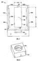
Fig. 1 , anapparatus 100 for purifying an oil-based fluid includes ahousing 110 within which adrum 140 is rotatingly retained, a means for rotating thedrum 160, and ascraper head 170. - The structure of the
housing 110, shown inFigs. 2 , includes twoside walls housing floor 116 extends. Asplash guard 120 may extend upward from thehousing floor 116 around the drum 140 (shown in Fug. 1). Aninlet 122 is through afirst side wall 112 and anoutlet 126 is present through asecond side wall 114. In theinlet 122 and theoutlet 126 are serially aligned with other fluid handling (not shown) through which drilling fluid 106 (shown inFig. 4 ) may be directed. - The
first side wall 112 may be seen inFig. 3 . Thesecond side wall 114 is a mirror image of thefirst side wall 112, with theinlet 122 on thefirst side wall 112 being replaced with the outlet 126 (shown inFig. 2 ) on thesecond side wall 114. Aslot 130 may be present through both first andsecond side walls slot 130 will permit the height, known as the drum height 142 (shown inFig. 4 ), between the drum 140 (shown inFig. 4 ) and the housing floor 116 (shown inFig. 4 ) to be adjusted. - As depicted in
Fig. 5 , thedrum 140 has a drumouter surface 144 extending betweendrum ends Figs. 1 and4 , eachdrum end outer surface 144 is adrum height 142 from thehousing floor 116. Eachend housing side wall 112, 114 (shown inFig, 1 ) provided that is insulated between thedrum end housing wall drum 140 is retained at eachdrum end Fig. 1 ), described in detail below, which allows adjustability of thedrum height 142. - As shown in
Fig. 4 , thehousing floor 116 is preferably shaped to complement the drumouter surface 144 while directing the contaminatedfluid 106 along its length 118 (shown inFig. 2 ) from theinlet 122 to theoutlet 126. The complementary shape of thehousing floor 116 ensures that all of thefluid 106 directed between thehousing 110 and thedrum 140 is within range of thedrum height 142. Further, there are no corners for accumulation of solids or other foreign objects. - The means for rotating the
drum 160 includes motors, cranks, or any other power generating means in combination with gears, belts, flywheels, or any other energy-transferring means. The preferred embodiment, shown inFig. 1 , includes avariable speed motor 162 with adrive wheel 164. Anaxle 152 extends from eachdrum end axle wheel 166. Rotation from themotor 162 is transmitted to thedrive wheel 164, which pulls the belt 168. The belt 168 rotates theaxle wheel 166. Theaxle 152 is keyed or affixed to theaxle drive wheel 166 so that as theaxle wheel 166 is rotated by the belt 168, theaxle 152 is also rotated. Thedrum 140 is rotated such that a point on the drum outer surface. 144 is subjected to the contaminatedfluid scream 106 where it contaminants rotated toward thesplash guard 120 and rotated past thescraper heat 170 before being rotated back into the contaminatedfluid stream 106. - Referring to
Figs. 1 and4 , thescraper head 170 preferably contacts the drumouter surface 144 along its downward rotation. Although thescraper head 170 may be positioned such that it contacts the drum outer surface. 144 along its length, a majority of the accumulatedcontaminants 108 may be removed from the drumouter surface 144 by positioning thescraper heat 170 less than a predetermined maximum distance (not shown) from, but not contacting, the drumouter surface 144. Thescraper heat 170 may be replaceable and include ascraper 172 and aflow director 173, Thescraper 172 is preferably made from a plastic or other nonconductive composite material that will resist wear while being of sufficient strength to scrape material from the drum outer surface. 144 without deforming. Thescraper 172 may be attached to theflow director 173 or thescraper 172 andflow director 173 may be formed as a single unit. -
Accumulated contaminants 108 are from the drumouter surface 144 by thescraper 172. After removal from the drumouter surface 144, theflow director 173 may guidecontaminants 108 toward acollection area 176 or processing area (not shown), away from thedrum 140 andhousing 110. Aslide 174 or other conveyance means (not shown) may be used to move contaminants to thecollection area 176. - As referred to earlier, a take up
unit 180, depicted in Fag. 6, may be included to adjust thedrum height 142 between the drum outer surface. 144 and thehousing floor 116, When included, a take upunit 180 is placed on each of the first andsecond side walls unit 180 will be discussed in the context of thefirst side wall 112, and those of skill in the art will appreciate that the same structure is present for the take upunit 180 on thesecond side wall 114, The take upunit 180 includes abracket 182, adrum support 206 and aheight adjuster 216. - The
bracken 182 has a mountingplate 184 having abracket slot 186 through which the axle 152 (shown inFig. 6 ) will extend. Thebracket slot 186 is defined by two opposingslot sides 188 and two opposing slot ends 192. The slot sides 188 have aside length 190 and the slot ends 192 have anend length 194, wherein theend length 194 is less than theside length 190, The mountingplate 184 is affixed to the side wall 112 (shown inFig. 6 ) of thehousing 110 such that thebracket slot 186 and theslot 130 in theside wall 112 are coaligned. - Two
guide members sides plate 184 and extend outward from the mountingplate 184 andhousing side wall 112. The slot sides 188 are aligned with theguide members guide rails surfaces guide members - A
height adjuster retainer 204 is located near one of the slot ends 192 and extends outward from the mountingplate 184. As will be discussed, theheight adjuster retainer 204 holds an intemally-thieaded datum member 218 (shown inFig. 6 ) in a fixed location. - Referring again to
Fig. 6 , thedrum support 206 has a pair ofopposed guide grooves 208, which interface with the guide rails 200. Theguide grooves 208 slide over theguide rails 200a, b so that thedrum support 206 is slidingly retained between theguide members 198a, b. A bearingsurface 210 retains therotatable axle 152. Aguide ring 212 is located at thelower end 214 of thedrum support 206 and provides an interface with theheight adjuster retainer 204. - The
height adjuster 216 includes a threadedadjustment member 222 and thedatum member 218. Thedatum member 218 is retained within theheight adjuster retainer 204 such that it is held with only nominal side-to-side and rotational movement possible. The threadedadjustment member 222 hasexternal threads 224 which interface with the internal threads 220 (shown inFig. 8 ) on thedatum member 218 to retain the threadedadjustment member 222 in a predetermined location. Afirst end 226 of theadjustment member 222, guided by theguide ring 212, contacts thedrum support 206. Asecond end 228 of theadjustment member 222 is located outside of the mountingbracket 182 where it is accessible to an operator wanting to adjust thedrum height 142. - When an operator wants to raise or lower the
drum 140, thesecond end 228 of theadjustment member 222 is rotated in the desired direction. Rotation in a first direction causes theadjustment member 222 to move linearly in a first direction with respect to the fixed location of thedatum member 218, Thedrum support 206, resting on theadjustment member 222, is raised or lowered by the linear movement of theadjustment member 222. Preferably, theadjustment members 222 on the take upunits 180 on eachside wall drum height 142 is uniform along the length 118 of thehousing floor 116. As will be discussed below, the take upunit 180 electrically isolates thedrum 160 from thehousing 110. - Referring again to
Fig. 1 ,motor height adjusters 230 are located on the skid on which themotor 162 is located. Proper tension of the belt 168 between theaxle wheel 166 and thedrive wheel 164 is necessary to ensure that themotor 162 efficiently rotates thedrum 140. Improper belt tension may cause the belt 168 to slip or break, depending upon whether the belt is under too little, or too much, tension. - The
housing 110 and themotor 162, when included, may be mounted onskids 102 for ease of handling and integrating into existing fluid processing systems. - In practice, tanks (not shown) or processing devices (not shown) are fluidly connected to the
inlet 122 and theoutlet 126 of thehousing 110, Turning toFig. 2 , aninlet valve 124 may be used to regulate or stop fluid flow through theinlet 122 into thehousing 110. Anoutlet valve 128 may be used to regulate or stop fluid flow through theoutlet 126 of thehousing 110. - Referring again to
Figs. 1 and4 , to separate thecontaminants 108 from the fluid 106, the contaminatedfluid 106 will be subjected to an electrical field caused by opposing electrical charges applied to thehousing 110 and thedrum 140. Thedrum 140 and thehousing 110 must be formed from a conductive material. As is discussed in detail below, certain interfaces between thedrum 140,housing 110, andground 104, therefore, must be insulated to insure the integrity of the electrical field. - Referring to
Figs. 1 and5 , theaxle 152, which is affixed to thedrum end housing side walls unit 180 is included, thehousing side wall plate 184, which may further be in electrical contact with thedrum support 206. Thus, the bearing surface 210 (shown inFig. 6 ) of thedrum support 206 must insulate theaxle 152 from thedrum support 206 to ensure that the electrical field between thedrum 140 and thehousing 110 is maintained. As theaxle 152 is operable by themotor 162, any contact between theaxle 152 and themotor 162 should also be insulated. As such, it may be preferable to fabricate theaxle wheel 166 from a nonconductive material. - The
housing 110 should be insulated from theground 104, as shown inFigs. 1 and4 . To accomplish this, thehousing 110 may be retained on one ormore pedestals 138 made from a non-conductive material. - The
scraper 172 may contact the drumouter surface 144. Theflow director 173, to which thescraper 172 may be attached or with which thescraper 172 may be formed, may contact theslide 174 or other conveyance means (not shown). Theslide 174 or conveyance means may, in turn,contact ground 104 or thehousing 110. Through such contact, the difference between the charge applied to thedrum 140 and the charge applied to thehousing 110 may be lost, resulting in a loss of the electrical field formed between them through which the contaminatedfluid 106 is directed. To provide insulated contact between thedrum 140 and thescraper head 170, thescraper 172 may be made from a nonconductive material. - Continuing to refer to
Figs. 1 and4 , thedrum height 142 should be adjusted so that the drumouter surface 144 is in contact with the fluid 106 along thehousing floor 116. One or more overflow valves 136 may be included on thehousing 110 to ensure that the fluid 106 does not overflow thehousing 110 in an uncontrolled flow. - A negative charge is applied to the
drum 140 and a positive charge is applied to thehousing 110. The negative charge attracts thecontaminants 108 in thefluid 106. Thecontaminants 108 migrate toward thedrum 140 and are held against the drumouter surface 144 by the electrical charge. - Once an electrical charge is applied to
housing 110 and an opposite electrical charge is applied to thedrum 140, thedrum 140 should be rotated to provide a clean surface upon which additional contaminants may collect and to extract collected contaminants from the fluid. Thedrum 140 may be rotated by any means, such as any type ofmotor 162 or a manual crank (not shown). In the preferred embodiment, amotor 162 is used to rotate thedrum 140. Themotor 162 may adjustable to vary the rotational speed of thedrum 140. - The
contaminants 108 collected on the drumouter surface 144 are removed by ascraper 172, which contacts the drumouter surface 144 as it begins its downward rotation. Thecontaminants 108 may then be directed to acollection area 176 away from thedrum 140 andhousing 110 by aslide 174. Thecollection area 176 may includeboxes 178 havingsensors 179 to alert an operator (not shown) when abox 178 is nearly full. Alternatively, thecollection area 176 may include conveyor (not shown) of other means to direct thecontaminants 108 away from theapparatus 100. - The ultra fine contaminants present in the oil-based fluid may be collected as the fluid flows through the
housing 110 or as batches of fluid are periodically contained within thehousing 110 and released. To collectcontaminants 108 from a batch offluid 106, theoutlet valve 128 is closed and theinlet valve 124 is opened to direct contaminatedfluid 106 into thehousing 110. After thehousing 110 is adequately filled, thedrum 140 may be adjusted to contact the contaminatedfluid 106. The means for rotating thedrum 160 is powered to provide rotation to thedrum 140 and opposing electrical charges are applied to thehousing 110 and thedrum 140. The ultrafine contaminants 108 are removed from the fluid when nofurther contaminants 108 are detected on the drumouter surface 144. - Alternatively, the contaminated oil-based
fluid 106 may be directed through thehousing 110 in a controlled flow. The contaminatedfluid 106 is directed through theinlet 122 and theoutlet valve 128 is opened such that the fluid will egress thehousing 110 through theoutlet 126. The flow should be controlled such that the fluid has adequate exposure to the electrical field between thehousing 110 and thedrum 140 forcontaminants 108 to collect on the drumouter surface 144. - Referring to
Figs. 9 and10 , a first alternative of theapparatus 300 is depicted. Theapparatus 300 has a plurality ofrotatable drums housing floor 316 preferably shaped to substantially complement the drumouter surfaces housing floor 316 and thedrums drum heights - The rotational direction of each
drum arrows Fig. 10 . As can be seen, thedrums drum scraper head housing 310, removes contaminants from the drumouter surface outer surface scraper head slide areas -
Multiple inlets 322 having avalve 324 may be used to direct fluid into thehousing 310. When a stream of contaminated fluid is to be treated by theapparatus 300, theinlets 322 are preferably located near opposite sides of the horsing 310 to maximize contact with the charged drumouter surface inlets 322 andoutlets 326 include avalve 324 to regulate flow of a contaminated fluid stream or to stop the fluid stream for batch processing. - A plurality of
drums Figs. 11 and12 . In this alternative, thedrums drums outer surfaces common slide 474. Theslide 474 may be slanted slightly downward, utilizing gravity to direct the contaminants to acollection area 476. - Each
scraper head common slide 474. Thus, as thedrums adjusting mechanism 475. Theadjusting mechanism 475 may include apositioning rod 476 having aslot 477 therethrough. Thepositioning rod 476, located at anend 473 of theslide 474, is flanked bylinkages linkages corresponding end scraper head linkages slot 477, resulting in a desired angular location of the scraper heads 470, 471. - The
housing 410 in thesecond alternative 400, has ahousing floor 416, preferably shaped to substantially complement shape of the drumouter surfaces valve 424 may be included through thehousing 410 to direct fluid into the space between thehousing floor 416 and thedrums apparatus 400, the inlets 422 are preferably located such that fluid initially is directed toward the area between thedrums 441. The complementary shape of thehousing floor 416 serves to direct the fluid flow such that contact with the charged drumouter surface outlets 426 include avalve 424 to regulate flow of a contaminated fluid stream or to stop the fluid stream for batch processing. - In an embodiment, shown in
Fig. 13 , a plurality ofdisks 540 may be spaced apart and retained on acommon axle 552 in place ofdrum 140. A first charge may be applied to thedisks 540 throughaxle 552 while an opposing charge is applied tohousing 110. Contaminants collect ondisks 540. Asdisks 540 rotate, contaminants from the fluid are adhered to the sides and end of eachdisk 540. Ascraper head 570 is used to remove the contaminants from eachdisk 540.Scraper head 570 includes a plurality oftines 571 positioned betweendisks 540 to remove collected contaminants from thedisks 540. Anonconductive lip 572 surrounds eachdisk 540 to insulate the chargeddisks 540 fromscraper head 570. - As depicted in
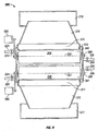
Fig. 14 , in an alternative embodiment, a plurality ofdisks 640 may be spaced apart and retained on acommon axle 652 in place ofdrum 140. A plurality ofplates 642 are placed in alternating positions with thedisks 640. Theplates 642 are configured with anotch 644 in atop surface 646 to avoid contact withaxle 652.Disks 640 are given a first charge whileplates 642 are given an opposing charge to create an electric field between eachdisk 640 andadjacent plate 642. Contaminants in the fluid collect ondisks 640. Asdisks 640 rotate, contaminants from the fluid adhere to the sides and end of eachdisk 640. Ascraper head 670 includes a plurality oftines 671 positioned betweendisks 640 andplates 642. Anonconductive lip 672 surrounds eachdisk 640 to insulate the chargeddisk 640 fromscraper head 670. Agap 674 is present between eachtine 671 and eachplate 642. - In each embodiment described,
housing 110 may include a means forheating 154, shown inFig. 4 , to heathousing floor 116. It has been found that as the viscosity of the contaminated fluid decreases, the collection of contaminants upon the drumouter surface 144 increases. Means forheating 154 may include heating elements beneath thehousing floor 116, which should be of a heat-conductive material. Means forheating 154 may include other beating sources such as a hot oil bath. - Each embodiment described may also include a
controller 156 operable to control the voltage between thedisks housing 110 orplates 642. Increasing the voltage between the opposingly charged surfaces while the current at a constant has been found to improve the performance of thedisks - For each of the alternative embodiments described, at least one means for rotating the
disks 560 is included. A single means for rotating thedrums 560 may be used to rotate bothdrums drums 560 may be included to rotate eachdrum drum 560 may include a motor, manual crank or other mechanical rotational device. - Also, take up
units 580 may be included at the interface between thehousing unit 580 may be used to raise or lower therespective drum housing floor - While the claimed subject matter has been described with respect to a limited number of embodiments, those skilled in the art, having benefit of this disclosure, will appreciate that other embodiments can be devised which do not depart from the scope of the claimed subject matter as disclosed herein. Accordingly, the scope of the claimed subject matter should be limited only by the attached claims.
Claims (5)
- An apparatus for removing contaminants from an oil-based fluid comprising:a housing (110) having a housing floor and a plurality of walls, wherein a contaminated oil-based fluid is contained within the walls and housing floor;a plurality of rotatable disks (540, 640), each disk having a disk outer surface retained a height above the housing floor and contacting the contaminated oil-based fluid;a means for rotating the disks (560); anda scraper head (570, 670) to remove contaminants collected on each disk, said scraper head including a plurality of tines (571, 671) located between the disks;characterised in that:said housing is electrically charged;said disks are oppositely charged to said housing; andsaid scraper head further includes a nonconductive lip (572, 672) which surrounds each disk.
- The apparatus of claim 1, further comprising:a plurality of electrically charged plates (642) extending from the housing floor between each disk.
- The apparatus of claim 1, further comprising:a means for heating the housing floor to decrease the viscosity of the fluid.
- The apparatus of claim 3 wherein the means for heating the housing floor includes a heating element retained beneath the housing floor.
- The apparatus of claim 1, further comprising:a controller operable to increase the voltage between the disks and the housing floor while maintaining a constant current.
Applications Claiming Priority (2)
| Application Number | Priority Date | Filing Date | Title |
|---|---|---|---|
| US63863104P | 2004-12-22 | 2004-12-22 | |
| EP05854438A EP1833613B1 (en) | 2004-12-22 | 2005-12-16 | Method and apparatus for purifying an oil-based fluid |
Related Parent Applications (2)
| Application Number | Title | Priority Date | Filing Date |
|---|---|---|---|
| EP05854438.8 Division | 2005-12-16 | ||
| EP05854438A Division EP1833613B1 (en) | 2004-12-22 | 2005-12-16 | Method and apparatus for purifying an oil-based fluid |
Publications (2)
| Publication Number | Publication Date |
|---|---|
| EP2474362A1 EP2474362A1 (en) | 2012-07-11 |
| EP2474362B1 true EP2474362B1 (en) | 2014-01-22 |
Family
ID=36602234
Family Applications (2)
| Application Number | Title | Priority Date | Filing Date |
|---|---|---|---|
| EP12158904.8A Not-in-force EP2474362B1 (en) | 2004-12-22 | 2005-12-16 | Method and apparatus for purifying an oil-based fluid |
| EP05854438A Not-in-force EP1833613B1 (en) | 2004-12-22 | 2005-12-16 | Method and apparatus for purifying an oil-based fluid |
Family Applications After (1)
| Application Number | Title | Priority Date | Filing Date |
|---|---|---|---|
| EP05854438A Not-in-force EP1833613B1 (en) | 2004-12-22 | 2005-12-16 | Method and apparatus for purifying an oil-based fluid |
Country Status (8)
| Country | Link |
|---|---|
| US (1) | US7686933B2 (en) |
| EP (2) | EP2474362B1 (en) |
| AR (1) | AR054718A1 (en) |
| CA (1) | CA2590128C (en) |
| EA (1) | EA010080B1 (en) |
| MX (1) | MX2007007749A (en) |
| NO (1) | NO20072877L (en) |
| WO (1) | WO2006068968A2 (en) |
Families Citing this family (13)
| Publication number | Priority date | Publication date | Assignee | Title |
|---|---|---|---|---|
| US7807047B2 (en) * | 2006-11-16 | 2010-10-05 | Gibson Energy Ulc | Reconditioning process for used hydrocarbon based stimulation fluid |
| US8088275B2 (en) * | 2006-11-16 | 2012-01-03 | Gibson Energy Ulc | Reconditioning process for used hydrocarbon based stimulation fluid |
| US8142634B2 (en) * | 2007-03-09 | 2012-03-27 | M-I L.L.C. | Method and apparatus for electrophoretic separation of solids and water from oil based mud |
| US20100122912A1 (en) * | 2008-11-19 | 2010-05-20 | Chardon Laboratories, Inc. | Water treatment device |
| US20100163415A1 (en) * | 2008-12-30 | 2010-07-01 | Chardon Laboratories, Inc. | Water treatment device |
| CA2776215A1 (en) | 2012-05-08 | 2013-11-08 | Sean Frisky | Electro-separation of oil-based drilling fluids |
| US9617811B2 (en) * | 2014-05-13 | 2017-04-11 | National Oilwell Varco, L.P. | Drilling mud cooling system |
| US10041314B2 (en) | 2014-07-08 | 2018-08-07 | National Oilwell Varco, L.P. | Closed loop drilling mud cooling system for land-based drilling operations |
| GB2552099B (en) | 2015-02-27 | 2021-05-12 | Halliburton Energy Services Inc | Solvent-induced separation of oilfield emulsions |
| US12023611B2 (en) | 2018-11-29 | 2024-07-02 | Hewlett-Packard Development Company, L.P. | Liquid carrier filtration |
| KR102150767B1 (en) * | 2018-12-06 | 2020-09-02 | (주)하나하드닝 | oil separator |
| CN113597581A (en) * | 2019-07-31 | 2021-11-02 | 惠普发展公司,有限责任合伙企业 | Filtration of carrier liquid using electric field |
| MX2024003508A (en) * | 2021-09-22 | 2024-04-08 | Nat Oilwell Varco Lp | Drilling fluid conditioning systems and methods. |
Family Cites Families (10)
| Publication number | Priority date | Publication date | Assignee | Title |
|---|---|---|---|---|
| US2109131A (en) * | 1935-05-25 | 1938-02-22 | Union Oil Co | Process and apparatus for dewaxing oil |
| FR1533226A (en) * | 1967-01-24 | 1968-07-19 | Manufactures De Carrelages Cer | Firming and drying process for ceramic pastes |
| US3825484A (en) * | 1971-04-29 | 1974-07-23 | N Fronsman | Electrolytic regenerator for chemical etchants including scraper means and rotating cathodes |
| US3970536A (en) * | 1974-08-22 | 1976-07-20 | Hydromation Filter Company | Liquid treating method and apparatus |
| US4090937A (en) * | 1976-07-28 | 1978-05-23 | Vish Minno-Geoloshki Institute | Electrophoretic technique for varying the concentration of a colloidal solution |
| SU919710A1 (en) * | 1980-03-04 | 1982-04-15 | Ленинградский Ордена Трудового Красного Знамени Инженерно-Строительный Институт | Liquid cleaning method |
| US4305797A (en) * | 1980-11-24 | 1981-12-15 | Carpco, Inc. | Material separation by dielectrophoresis |
| US4323445A (en) * | 1980-11-26 | 1982-04-06 | Alekhin S | Apparatus for electrokinetically separating drilling mud |
| US4444637A (en) | 1983-04-28 | 1984-04-24 | King Arthur S | Electrical treating apparatus having electrode cleaner |
| DE3832674A1 (en) * | 1988-09-27 | 1990-03-29 | Kodak Ag | METAL RECOVERY DEVICE |
-
2005
- 2005-12-16 MX MX2007007749A patent/MX2007007749A/en active IP Right Grant
- 2005-12-16 EP EP12158904.8A patent/EP2474362B1/en not_active Not-in-force
- 2005-12-16 CA CA2590128A patent/CA2590128C/en not_active Expired - Fee Related
- 2005-12-16 EP EP05854438A patent/EP1833613B1/en not_active Not-in-force
- 2005-12-16 WO PCT/US2005/045720 patent/WO2006068968A2/en active Application Filing
- 2005-12-16 US US11/303,111 patent/US7686933B2/en not_active Expired - Fee Related
- 2005-12-16 EA EA200701323A patent/EA010080B1/en not_active IP Right Cessation
- 2005-12-20 AR ARP050105386A patent/AR054718A1/en active IP Right Grant
-
2007
- 2007-06-06 NO NO20072877A patent/NO20072877L/en not_active Application Discontinuation
Also Published As
| Publication number | Publication date |
|---|---|
| WO2006068968A2 (en) | 2006-06-29 |
| EA010080B1 (en) | 2008-06-30 |
| CA2590128C (en) | 2013-12-03 |
| EP2474362A1 (en) | 2012-07-11 |
| WO2006068968A3 (en) | 2007-05-24 |
| EP1833613A4 (en) | 2010-12-22 |
| EA200701323A1 (en) | 2007-10-26 |
| CA2590128A1 (en) | 2006-06-29 |
| EP1833613B1 (en) | 2012-05-30 |
| US20060131247A1 (en) | 2006-06-22 |
| AR054718A1 (en) | 2007-07-11 |
| NO20072877L (en) | 2007-09-18 |
| EP1833613A2 (en) | 2007-09-19 |
| WO2006068968A8 (en) | 2007-07-19 |
| MX2007007749A (en) | 2007-08-21 |
| US7686933B2 (en) | 2010-03-30 |
Similar Documents
| Publication | Publication Date | Title |
|---|---|---|
| EP2474362B1 (en) | Method and apparatus for purifying an oil-based fluid | |
| US8142634B2 (en) | Method and apparatus for electrophoretic separation of solids and water from oil based mud | |
| CN111189313B (en) | Sediment drying device | |
| US11639640B2 (en) | Electro-separation cell with solids removal | |
| JP2006326445A (en) | Separation recovery device and method of contained material in waste liquid such as recovery coolant | |
| CA2704047C (en) | Pressure filter with vibrator | |
| KR102118229B1 (en) | Compartmentally expandable rotating belt filter for energy use reduction | |
| EP0825895B1 (en) | Improvements in and relating to vibratory screening apparatus | |
| KR101109551B1 (en) | Semiconductor Wastewater treatment plant | |
| CN210559512U (en) | Automatic oil-water separator with lead screw oil scraping device | |
| EP3052245B1 (en) | Centrifugal separator | |
| JPH0418641Y2 (en) | ||
| CN213175563U (en) | High-efficient clean processing system of well drilling waste liquid | |
| RU2048463C1 (en) | Device for cleaning suspensions of organomineral substances, mainly sapropel and/or peat from solid fraction | |
| KR101309906B1 (en) | Apparatus for separating off bottom dross from polluted water | |
| SU1666189A2 (en) | Filtering centrifuge | |
| RU57269U1 (en) | INTEGRATED TECHNOLOGICAL MODULE FOR THIN-LAYER CLEANING OF LARGE VOLUMES OF WATER FROM MECHANICAL IMPURITIES AND OIL PRODUCTS | |
| JP2007237051A (en) | Magnetic separation conveying device | |
| JP2018034120A (en) | Separation device for separating and recovering oil and impurities from liquid (emulsion) emulsified by mixing of oil and water | |
| JP2009112983A (en) | Electrostatic oil cleaning apparatus | |
| NL8002632A (en) | Separating drill cuttings from drilling mud - by applying DC field to layer of mud adhering to rotating drum partly immersed in mud |
Legal Events
| Date | Code | Title | Description |
|---|---|---|---|
| PUAI | Public reference made under article 153(3) epc to a published international application that has entered the european phase |
Free format text: ORIGINAL CODE: 0009012 |
|
| 17P | Request for examination filed |
Effective date: 20120322 |
|
| AC | Divisional application: reference to earlier application |
Ref document number: 1833613 Country of ref document: EP Kind code of ref document: P |
|
| AK | Designated contracting states |
Kind code of ref document: A1 Designated state(s): AT BE BG CH CY CZ DE DK EE ES FI FR GB GR HU IE IS IT LI LT LU LV MC NL PL PT RO SE SI SK TR |
|
| GRAP | Despatch of communication of intention to grant a patent |
Free format text: ORIGINAL CODE: EPIDOSNIGR1 |
|
| INTG | Intention to grant announced |
Effective date: 20130823 |
|
| GRAS | Grant fee paid |
Free format text: ORIGINAL CODE: EPIDOSNIGR3 |
|
| GRAA | (expected) grant |
Free format text: ORIGINAL CODE: 0009210 |
|
| AC | Divisional application: reference to earlier application |
Ref document number: 1833613 Country of ref document: EP Kind code of ref document: P |
|
| AK | Designated contracting states |
Kind code of ref document: B1 Designated state(s): AT BE BG CH CY CZ DE DK EE ES FI FR GB GR HU IE IS IT LI LT LU LV MC NL PL PT RO SE SI SK TR |
|
| REG | Reference to a national code |
Ref country code: GB Ref legal event code: FG4D |
|
| REG | Reference to a national code |
Ref country code: CH Ref legal event code: EP |
|
| REG | Reference to a national code |
Ref country code: AT Ref legal event code: REF Ref document number: 650511 Country of ref document: AT Kind code of ref document: T Effective date: 20140215 |
|
| REG | Reference to a national code |
Ref country code: IE Ref legal event code: FG4D |
|
| REG | Reference to a national code |
Ref country code: DE Ref legal event code: R096 Ref document number: 602005042615 Country of ref document: DE Effective date: 20140306 |
|
| REG | Reference to a national code |
Ref country code: NL Ref legal event code: VDEP Effective date: 20140122 |
|
| REG | Reference to a national code |
Ref country code: AT Ref legal event code: MK05 Ref document number: 650511 Country of ref document: AT Kind code of ref document: T Effective date: 20140122 |
|
| REG | Reference to a national code |
Ref country code: LT Ref legal event code: MG4D |
|
| PG25 | Lapsed in a contracting state [announced via postgrant information from national office to epo] |
Ref country code: LT Free format text: LAPSE BECAUSE OF FAILURE TO SUBMIT A TRANSLATION OF THE DESCRIPTION OR TO PAY THE FEE WITHIN THE PRESCRIBED TIME-LIMIT Effective date: 20140122 Ref country code: IS Free format text: LAPSE BECAUSE OF FAILURE TO SUBMIT A TRANSLATION OF THE DESCRIPTION OR TO PAY THE FEE WITHIN THE PRESCRIBED TIME-LIMIT Effective date: 20140522 |
|
| PG25 | Lapsed in a contracting state [announced via postgrant information from national office to epo] |
Ref country code: CY Free format text: LAPSE BECAUSE OF FAILURE TO SUBMIT A TRANSLATION OF THE DESCRIPTION OR TO PAY THE FEE WITHIN THE PRESCRIBED TIME-LIMIT Effective date: 20140122 Ref country code: NL Free format text: LAPSE BECAUSE OF FAILURE TO SUBMIT A TRANSLATION OF THE DESCRIPTION OR TO PAY THE FEE WITHIN THE PRESCRIBED TIME-LIMIT Effective date: 20140122 Ref country code: PT Free format text: LAPSE BECAUSE OF FAILURE TO SUBMIT A TRANSLATION OF THE DESCRIPTION OR TO PAY THE FEE WITHIN THE PRESCRIBED TIME-LIMIT Effective date: 20140522 Ref country code: ES Free format text: LAPSE BECAUSE OF FAILURE TO SUBMIT A TRANSLATION OF THE DESCRIPTION OR TO PAY THE FEE WITHIN THE PRESCRIBED TIME-LIMIT Effective date: 20140122 Ref country code: AT Free format text: LAPSE BECAUSE OF FAILURE TO SUBMIT A TRANSLATION OF THE DESCRIPTION OR TO PAY THE FEE WITHIN THE PRESCRIBED TIME-LIMIT Effective date: 20140122 Ref country code: FI Free format text: LAPSE BECAUSE OF FAILURE TO SUBMIT A TRANSLATION OF THE DESCRIPTION OR TO PAY THE FEE WITHIN THE PRESCRIBED TIME-LIMIT Effective date: 20140122 Ref country code: SE Free format text: LAPSE BECAUSE OF FAILURE TO SUBMIT A TRANSLATION OF THE DESCRIPTION OR TO PAY THE FEE WITHIN THE PRESCRIBED TIME-LIMIT Effective date: 20140122 |
|
| PG25 | Lapsed in a contracting state [announced via postgrant information from national office to epo] |
Ref country code: LV Free format text: LAPSE BECAUSE OF FAILURE TO SUBMIT A TRANSLATION OF THE DESCRIPTION OR TO PAY THE FEE WITHIN THE PRESCRIBED TIME-LIMIT Effective date: 20140122 Ref country code: BE Free format text: LAPSE BECAUSE OF FAILURE TO SUBMIT A TRANSLATION OF THE DESCRIPTION OR TO PAY THE FEE WITHIN THE PRESCRIBED TIME-LIMIT Effective date: 20140122 |
|
| REG | Reference to a national code |
Ref country code: DE Ref legal event code: R097 Ref document number: 602005042615 Country of ref document: DE |
|
| PG25 | Lapsed in a contracting state [announced via postgrant information from national office to epo] |
Ref country code: EE Free format text: LAPSE BECAUSE OF FAILURE TO SUBMIT A TRANSLATION OF THE DESCRIPTION OR TO PAY THE FEE WITHIN THE PRESCRIBED TIME-LIMIT Effective date: 20140122 Ref country code: CZ Free format text: LAPSE BECAUSE OF FAILURE TO SUBMIT A TRANSLATION OF THE DESCRIPTION OR TO PAY THE FEE WITHIN THE PRESCRIBED TIME-LIMIT Effective date: 20140122 Ref country code: DK Free format text: LAPSE BECAUSE OF FAILURE TO SUBMIT A TRANSLATION OF THE DESCRIPTION OR TO PAY THE FEE WITHIN THE PRESCRIBED TIME-LIMIT Effective date: 20140122 Ref country code: RO Free format text: LAPSE BECAUSE OF FAILURE TO SUBMIT A TRANSLATION OF THE DESCRIPTION OR TO PAY THE FEE WITHIN THE PRESCRIBED TIME-LIMIT Effective date: 20140122 |
|
| PG25 | Lapsed in a contracting state [announced via postgrant information from national office to epo] |
Ref country code: SK Free format text: LAPSE BECAUSE OF FAILURE TO SUBMIT A TRANSLATION OF THE DESCRIPTION OR TO PAY THE FEE WITHIN THE PRESCRIBED TIME-LIMIT Effective date: 20140122 Ref country code: PL Free format text: LAPSE BECAUSE OF FAILURE TO SUBMIT A TRANSLATION OF THE DESCRIPTION OR TO PAY THE FEE WITHIN THE PRESCRIBED TIME-LIMIT Effective date: 20140122 |
|
| PLBE | No opposition filed within time limit |
Free format text: ORIGINAL CODE: 0009261 |
|
| STAA | Information on the status of an ep patent application or granted ep patent |
Free format text: STATUS: NO OPPOSITION FILED WITHIN TIME LIMIT |
|
| 26N | No opposition filed |
Effective date: 20141023 |
|
| REG | Reference to a national code |
Ref country code: DE Ref legal event code: R097 Ref document number: 602005042615 Country of ref document: DE Effective date: 20141023 |
|
| PG25 | Lapsed in a contracting state [announced via postgrant information from national office to epo] |
Ref country code: SI Free format text: LAPSE BECAUSE OF FAILURE TO SUBMIT A TRANSLATION OF THE DESCRIPTION OR TO PAY THE FEE WITHIN THE PRESCRIBED TIME-LIMIT Effective date: 20140122 |
|
| REG | Reference to a national code |
Ref country code: DE Ref legal event code: R119 Ref document number: 602005042615 Country of ref document: DE |
|
| PG25 | Lapsed in a contracting state [announced via postgrant information from national office to epo] |
Ref country code: LU Free format text: LAPSE BECAUSE OF FAILURE TO SUBMIT A TRANSLATION OF THE DESCRIPTION OR TO PAY THE FEE WITHIN THE PRESCRIBED TIME-LIMIT Effective date: 20141216 |
|
| REG | Reference to a national code |
Ref country code: CH Ref legal event code: PL |
|
| GBPC | Gb: european patent ceased through non-payment of renewal fee |
Effective date: 20141216 |
|
| REG | Reference to a national code |
Ref country code: IE Ref legal event code: MM4A |
|
| REG | Reference to a national code |
Ref country code: FR Ref legal event code: ST Effective date: 20150831 |
|
| PG25 | Lapsed in a contracting state [announced via postgrant information from national office to epo] |
Ref country code: GB Free format text: LAPSE BECAUSE OF NON-PAYMENT OF DUE FEES Effective date: 20141216 Ref country code: LI Free format text: LAPSE BECAUSE OF NON-PAYMENT OF DUE FEES Effective date: 20141231 Ref country code: DE Free format text: LAPSE BECAUSE OF NON-PAYMENT OF DUE FEES Effective date: 20150701 Ref country code: CH Free format text: LAPSE BECAUSE OF NON-PAYMENT OF DUE FEES Effective date: 20141231 Ref country code: IE Free format text: LAPSE BECAUSE OF NON-PAYMENT OF DUE FEES Effective date: 20141216 |
|
| PG25 | Lapsed in a contracting state [announced via postgrant information from national office to epo] |
Ref country code: FR Free format text: LAPSE BECAUSE OF NON-PAYMENT OF DUE FEES Effective date: 20141231 |
|
| PG25 | Lapsed in a contracting state [announced via postgrant information from national office to epo] |
Ref country code: BG Free format text: LAPSE BECAUSE OF FAILURE TO SUBMIT A TRANSLATION OF THE DESCRIPTION OR TO PAY THE FEE WITHIN THE PRESCRIBED TIME-LIMIT Effective date: 20140122 Ref country code: MC Free format text: LAPSE BECAUSE OF FAILURE TO SUBMIT A TRANSLATION OF THE DESCRIPTION OR TO PAY THE FEE WITHIN THE PRESCRIBED TIME-LIMIT Effective date: 20140122 |
|
| PG25 | Lapsed in a contracting state [announced via postgrant information from national office to epo] |
Ref country code: GR Free format text: LAPSE BECAUSE OF FAILURE TO SUBMIT A TRANSLATION OF THE DESCRIPTION OR TO PAY THE FEE WITHIN THE PRESCRIBED TIME-LIMIT Effective date: 20140423 Ref country code: IT Free format text: LAPSE BECAUSE OF FAILURE TO SUBMIT A TRANSLATION OF THE DESCRIPTION OR TO PAY THE FEE WITHIN THE PRESCRIBED TIME-LIMIT Effective date: 20140122 |
|
| PG25 | Lapsed in a contracting state [announced via postgrant information from national office to epo] |
Ref country code: HU Free format text: LAPSE BECAUSE OF FAILURE TO SUBMIT A TRANSLATION OF THE DESCRIPTION OR TO PAY THE FEE WITHIN THE PRESCRIBED TIME-LIMIT; INVALID AB INITIO Effective date: 20051216 Ref country code: TR Free format text: LAPSE BECAUSE OF FAILURE TO SUBMIT A TRANSLATION OF THE DESCRIPTION OR TO PAY THE FEE WITHIN THE PRESCRIBED TIME-LIMIT Effective date: 20140122 |
|
| P01 | Opt-out of the competence of the unified patent court (upc) registered |
Effective date: 20231216 |