EP2473322B1 - An automated system and method for disassembling, handling and reassembling devices for containing animals in a lab animal room - Google Patents
An automated system and method for disassembling, handling and reassembling devices for containing animals in a lab animal room Download PDFInfo
- Publication number
- EP2473322B1 EP2473322B1 EP10759828.6A EP10759828A EP2473322B1 EP 2473322 B1 EP2473322 B1 EP 2473322B1 EP 10759828 A EP10759828 A EP 10759828A EP 2473322 B1 EP2473322 B1 EP 2473322B1
- Authority
- EP
- European Patent Office
- Prior art keywords
- cage
- cages
- feeder
- previous
- automated
- Prior art date
- Legal status (The legal status is an assumption and is not a legal conclusion. Google has not performed a legal analysis and makes no representation as to the accuracy of the status listed.)
- Active
Links
- 241001465754 Metazoa Species 0.000 title claims description 24
- 238000000034 method Methods 0.000 title claims description 22
- 238000001514 detection method Methods 0.000 claims 5
- 230000002093 peripheral effect Effects 0.000 claims 1
- 238000005406 washing Methods 0.000 description 20
- 230000000694 effects Effects 0.000 description 7
- 230000000903 blocking effect Effects 0.000 description 4
- 239000000463 material Substances 0.000 description 3
- 239000002184 metal Substances 0.000 description 3
- 230000009471 action Effects 0.000 description 2
- 239000013566 allergen Substances 0.000 description 2
- 239000010794 food waste Substances 0.000 description 2
- 206010051841 Exposure to allergen Diseases 0.000 description 1
- 230000008878 coupling Effects 0.000 description 1
- 238000010168 coupling process Methods 0.000 description 1
- 238000005859 coupling reaction Methods 0.000 description 1
- 239000006185 dispersion Substances 0.000 description 1
- 238000006073 displacement reaction Methods 0.000 description 1
- 239000000428 dust Substances 0.000 description 1
- 230000007613 environmental effect Effects 0.000 description 1
- 230000006872 improvement Effects 0.000 description 1
- 230000001939 inductive effect Effects 0.000 description 1
- 239000007769 metal material Substances 0.000 description 1
- 238000012986 modification Methods 0.000 description 1
- 230000004048 modification Effects 0.000 description 1
- 230000001681 protective effect Effects 0.000 description 1
- 230000003252 repetitive effect Effects 0.000 description 1
- 238000007789 sealing Methods 0.000 description 1
Images


Classifications
-
- B—PERFORMING OPERATIONS; TRANSPORTING
- B25—HAND TOOLS; PORTABLE POWER-DRIVEN TOOLS; MANIPULATORS
- B25J—MANIPULATORS; CHAMBERS PROVIDED WITH MANIPULATION DEVICES
- B25J15/00—Gripping heads and other end effectors
- B25J15/02—Gripping heads and other end effectors servo-actuated
- B25J15/0253—Gripping heads and other end effectors servo-actuated comprising parallel grippers
-
- A—HUMAN NECESSITIES
- A01—AGRICULTURE; FORESTRY; ANIMAL HUSBANDRY; HUNTING; TRAPPING; FISHING
- A01K—ANIMAL HUSBANDRY; CARE OF BIRDS, FISHES, INSECTS; FISHING; REARING OR BREEDING ANIMALS, NOT OTHERWISE PROVIDED FOR; NEW BREEDS OF ANIMALS
- A01K1/00—Housing animals; Equipment therefor
- A01K1/02—Pigsties; Dog-kennels; Rabbit-hutches or the like
- A01K1/03—Housing for domestic or laboratory animals
- A01K1/031—Cages for laboratory animals; Cages for measuring metabolism of animals
Definitions
- the present invention concerns an automated system for handling devices for containing animals, and particularly for the containment devices used to house animals used in scientific research.
- cages suitable for containing lab animals under controlled environmental conditions.
- such cages include a plurality of structural elements that are designed to serve various purposes, but they all comprise at least one tray suitable for containing the animals, at least one feeder, generally with a mesh structure or metal grid, and at least one lid for hermetically sealing the cage.
- the tray containing the animals is filled with a litter or bedding of material, normally sawdust, suitable for absorbing the animals' excrement, and this bedding material must consequently be periodically replaced.
- the containment cage must also be suitably washed and sterilised, a procedure that is normally done by the operator with the aid of a discontinuous procedure, typically using machines for washing general items or trays, or by means of continuous washing machines, based on the use of a conveyor belt, for instance.
- the operator has to collect the soiled cage containing the bedding from a shelf coming from the lab animal room, then open the cage or at least remove the lid and the feeder, emptying it into a specific hopper for collecting the bedding and then place all the disassembled parts in the washing machine or on the conveyor belt serving the continuous washing machine.
- US-A-2005 166 860 discloses the automated handling of disassembled parts of animal cages, in particular bottoms and lids.
- the main aim of the present invention is thus to produce a system and a method for the automated handling of lab animal containment devices.
- one object of the present invention is to reduce the time it takes to disassemble, empty, wash and reassemble the cages, with a consequent optimisation of the laboratory activity times.
- the system 1 comprises automated means for handling and moving the cages.
- said automated means may preferably comprise a robot and, even more preferably, an anthropomorphous robotic arm 2.
- Said automated means of movement also comprise at least one gripping member 3, connected to the movable end of said robotic arm 2, and specifically structured to be able to hold the assembled cage and/or single components thereof.
- the robotic arm 2 is designed so that it can be oriented in space in order to position the gripping member 3 in any point in space, thanks to the simultaneous presence of a plurality of axes of movement A, B , C, D and E.
- the closed, soiled cages are carried with the aid of a transport cart 20, in which they are stacked tidily.
- the transport cart 20 is then placed alongside the robotic arm 2, in a position that enables the robotic arm to reach each cage. Since the transport carts of known type are normally mounted on wheels specifically to facilitate their displacement, for such a cart 20 to be suitable for use with the automated system according to the present invention special locking means must be provided to block the cart firmly in a previously-established position, so that it is held steady, in the right position in relation to the robotic arm, while said arm transfers the cages.
- Said blocking means suitably comprise a clamping hook designed to hold the cart within a corresponding slot fixed to the wall or floor, said clamping hook being suitable for being operated by an electro-hydraulic device, and said device being capable of communicating with the system's central control unit.
- the system according to the present invention also comprises a disassembly station 60.
- Said disassembly station 60 comprises a supporting surface 61 and a plurality of control sensors suitable for detecting a plurality of data and transferring it to the robot's control unit.
- the disassembly station 60 comprises a plurality of sensors. At least one sensor 62 is preferably for checking for the presence of a cage, at least one control sensor 63 checks the orientation of the cage, and at least one sensor 64 checks for the presence of the feeder. Said sensor 64 for checking for the president of a feeder may consist of an inductive sensor, for instance, that is capable of identifying the presence of any metal material.
- the lab animal containment cages are generally made of plastic, while the feeder is normally the only component of the cage to be made of metal.
- At least one blocking actuator 65 designed to retain the cage on the supporting surface 61, and a plurality of devices 66 to position the cage correctly on the supporting surface 61.
- FIGS 3 and 4 show an example of a lab animal containment cage suitable for handling by the system 1 according to the present invention.
- Said cage 100 consists substantially of three components, i.e. a tray 101 suitable for containing animals and for being filled with a material for use as bedding, a lid 102 suitable for closing the cage, and a feeder 103 that can consist of a metal grid, for instance.
- the cage may be of the type comprising a closing system with a push button control 104 for releasing the lid.
- a closing system with a push button control 104 for releasing the lid.
- One type of cage widely used in lab animal rooms involves the presence of two buttons for releasing the lid, located on two opposite sides of the cage.
- the disassembly station 60 comprises means for opening the cage, comprising an actuator 67, for instance, capable of releasing the lid 102 by means of a pressure on the buttons 104.
- an actuator 67 for instance, capable of releasing the lid 102 by means of a pressure on the buttons 104.
- the content illustrated herein as regards the lab animal containment cages may not be construed to limit the present invention in any way, because the cages may be of any, even very different shape, since the system 1 according to the present invention is easily adaptable to other types of cage.
- the robotic arm 2 of the system 1 comprises a gripper 3 suitable for holding the whole cage and each single component thereof.
- the gripper 3 comprises a head 3d with which cage gripping means are associated, said cage gripping means comprising, for instance, a clamp consisting of two jaws 3a and 3b slidingly associated with said head 3d in the direction identified by the arrows A in figure 8a , i.e. so that they can be moved closer together or further apart.
- the gripping member 3 also comprises further gripping means for holding the feeder 103.
- Said gripping means for holding the feeder comprise at least one actuator 3g consisting of a piston terminating with a head 3e, first locator means 3h on the feeder 103 comprising, for instance, a pair of slots 3f designed to contain a stretch of the perimeter of said feeder 103, as shown in figures 8c and 8d , and at least second locator means 3c shaped like a flange, for instance, against which said head 3e (that is movable perpendicularly to said locator means 3c, in the direction B of figure 8b ) is designed to close the perimeter stretch of feeder positioned between the portions inserted in the two slots 3f. Being capable of movement perpendicular to said locator means 3c, said head 3e holds the feeder 103 by gripping a stretch of one of its ends.
- the soiled cages are generally placed on a storage device that may, for instance, consist of a transport cart 20; they may be deposited in a storage area inside the lab animal room before they are carried to the area for the disassembly and emptying of the cages.
- an extractor hood with a laminar flow 40 comprising a hopper 41 where the bedding or litter from the cage is collected, while the hood prevents the dispersion of any allergens in the environment.
- the system according to the present invention enables the automated disassembly of the cages 100.
- the cages are collected from the transport cart 20 by the robotic arm 2, the cage being held by the gripping member 3 as shown in figure 5 .
- the gripping action achieved by the two juxtaposed jaws 3a and 3b makes contact with the cage in line with two opposite lateral surfaces and the tightening of the jaws ensures the gripping of the cage.
- the cage While still assembled, the cage is thus deposited at the disassembly station 60 in line with locator devices 66 designed to orient its position.
- the sensors 62, 63 and 64 respectively detect the presence of a cage at the disassembly station 60, the orientation of said cage, and the presence of a feeder 103, and they transfer this information to the control unit governing the robotic arm 2.
- the control unit monitors the movements of the robotic arm and controls its operation.
- the blocking actuator 65 holds the cage in position on the surface 61.
- the lid 102 of the cage is released from the tray 101, while the sensor 63 checks the orientation of the cage, so that the robotic arm can grasp the lid 102 in the correct position.
- the gripping member 3 of the robotic arm 2 hold the lid 102 by means of the jaws 3a and 3b of the gripping member 3 and the lid is removed from the cage, the robotic arm 2 again moving on the strength of information relating to the orientation of the cage provided by the sensors at the disassembly station 60.
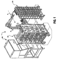
- the robotic arm 2 can then deposit the lid on a cart or delivery shelf 30, in the case of a discontinuous washing procedure, as shown in figure 1 , or directly on a conveyor belt leading into a tunnel washer 50, as shown in figure 2 , in the case of a continuous washing procedure.
- the gripper 3 of the robotic arm 2 picks up the feeder 103 with the aid of the means for the feeder.
- the sensor 64 for detecting the presence of the feeder informs the control unit of the presence or absence of the feeder so that the robotic arm can skip this phase if there is no feeder to remove.
- the control software can make the robot turn the feeder 103 upside down, so that any contents in the feeder, e.g. any food scraps remaining on its surface, can drop back into the tray 101.
- the robotic arm 2 After the robotic arm 2 has completed, where necessary, this procedure to empty the feeder 103 of any food scraps, it again deposits the feeder on the cart or delivery shelf 30 in the case of a discontinuous washing procedure, or directly on the conveyor belt leading into the tunnel washer 50, shown in figure 2 , in the case of a continuous washing procedure.
- the robot's gripping jaws 3a, 3b grasp the tray 101 (that has been released in the meantime from the constraint exerted by the blocking actuator 65), lifting the tray off the surface 61 of the disassembly station 60 and bringing it into line with the hopper 41 under the extractor hood with a laminar flow 40, where it is turned upside down in order to empty its contents into the hopper.
- the tray After the tray has been emptied, it too is loaded onto the cart or delivery shelf 30 in the case of a discontinuous washing procedure, or directly onto the conveyor belt for delivery to the tunnel washer 50 in the case of a continuous washing procedure.
- This sequence of operations or disassembly of the cages and emptying of the bedding contained in the trays is repeated automatically by the robot for every cage contained on the transport shelf 20, or other generic storage structure, and a tray sensor can be suitably provided in line with the gripper 3 too, so that the system automatically identifies the presence of a cage on the storage shelf.
- a similar system comprising a robotic arm and a re-assembly station can be provided at the outlet from the tunnel washer so as to automate the procedure for the reassembly of the cages too, after they have been washed - procedures that otherwise have to be completed by hand.
- the system according to the present invention enables the completely automated disassembly and emptying of the cages without any need for the operator to take any manual action, thereby optimising the research personnel's activities at the laboratory by leaving them free to dedicate themselves to their research activities.
- Another object achieved by the system according to the present invention is that of drastically reducing the time it takes to disassemble, empty and wash the cages, with a consequent optimisation of the time available for the laboratory activities, and consequently also of the related costs.
- the automated system reduces to a minimum any risk of the operator coming into contact with allergens and dust in relation to the devices used in the lab animal room to contain the animals and their bedding.
- system according to the present invention may also be used to reassemble the cages at the end of the washing procedure.
- a possible application might, for instance, include the presence of one system according to the present invention at the inlet to a continuous tunnel washer, such as the one described herein, and the presence of a second system according to the present invention that performs the same operations in reverse order, reassembling the cages when they exit from the tunnel washer.
- the reassembly of the cages might be handled automatically by the system according to the present invention, controlled by suitable software, also in combination with discontinuous washing machines.
Description
- The present invention concerns an automated system for handling devices for containing animals, and particularly for the containment devices used to house animals used in scientific research.
- It is common knowledge that research laboratories use shelves to contain a plurality of devices (generally cages) suitable for containing lab animals under controlled environmental conditions. In particular, such cages include a plurality of structural elements that are designed to serve various purposes, but they all comprise at least one tray suitable for containing the animals, at least one feeder, generally with a mesh structure or metal grid, and at least one lid for hermetically sealing the cage.
- The tray containing the animals is filled with a litter or bedding of material, normally sawdust, suitable for absorbing the animals' excrement, and this bedding material must consequently be periodically replaced. In addition, the containment cage must also be suitably washed and sterilised, a procedure that is normally done by the operator with the aid of a discontinuous procedure, typically using machines for washing general items or trays, or by means of continuous washing machines, based on the use of a conveyor belt, for instance.
- In any case, before the washing procedure, be it continuous or discontinuous, the operator has to collect the soiled cage containing the bedding from a shelf coming from the lab animal room, then open the cage or at least remove the lid and the feeder, emptying it into a specific hopper for collecting the bedding and then place all the disassembled parts in the washing machine or on the conveyor belt serving the continuous washing machine.
-
US-A-2005 166 860 discloses the automated handling of disassembled parts of animal cages, in particular bottoms and lids. - All these procedures for emptying and disassembling the cage, and placing them in the washing machine or on a movable shelf for feeding them into the washing machine, are currently handled manually by operators with a considerable loss of time, and at the risk of their direct exposure to allergens (which makes it compulsory for them to use a number of items of protective equipment) and with repeated movements that make this job boring, and consequently lowering the operators' attention levels and further slowing the procedures or extending the time it takes to clean the cages. The time that the operators or researchers spend disassembling and emptying the cages is time subtracted from the research activity proper.
- The main aim of the present invention is thus to produce a system and a method for the automated handling of lab animal containment devices.
- Within the context of this aim, one object of the present invention is to reduce the time it takes to disassemble, empty, wash and reassemble the cages, with a consequent optimisation of the laboratory activity times.
- This aim and this and other objects that will emerge more clearly later on are achieved by a system according to
claim 1 and a method according to claim 12. - Further characteristics and advantages of the present invention will emerge more clearly from the following detailed description, given as a non-limiting example and illustrated in the attached figures, wherein:
-
figure 1 shows an overall perspective view of the system according to the present invention in a possible embodiment suitable for application to a discontinuous washing process; -
figure 2 shows an overall perspective view of the system according to the present invention in a possible embodiment suitable for application to a continuous washing process; -
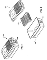
figure 3 shows a perspective view of a possible animal containment device suitable for being handled by the system according to the present invention; -
figure 4 shows an exploded view of the same containment cage as infigure 3 ; -
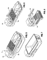
figure 5 shows a perspective view of the cage infigure 3 , held by a mechanical gripping member forming part of the system according to the present invention; -
figure 6 shows a perspective view of the lid on the cage as infigure 3 , held by a mechanical gripping member forming part of the system according to the present invention; -
figure 7 shows a perspective view of the tray forming part of the cage infigure 3 , held by a mechanical gripping member forming part of the system according to the present invention; -
figure 8 shows a perspective view of the feeder in the cage as infigure 3 , held by a mechanical gripping member forming part of the system according to the present invention; - figures from 8a to 8d show perspective views and views from below of the gripping member forming part of the system according to the present invention;
-
figure 9 shows a perspective view of the bench for supporting the system according to the present invention; -
figure 10 shows a perspective view of the supporting bench infigure 9 , as seen from a different angle. - With reference to
figure 1 , thesystem 1 according to the present invention comprises automated means for handling and moving the cages. - In particular, said automated means may preferably comprise a robot and, even more preferably, an anthropomorphous robotic arm 2.
- Said automated means of movement also comprise at least one gripping
member 3, connected to the movable end of said robotic arm 2, and specifically structured to be able to hold the assembled cage and/or single components thereof. The robotic arm 2 is designed so that it can be oriented in space in order to position the grippingmember 3 in any point in space, thanks to the simultaneous presence of a plurality of axes of movement A, B , C, D and E. - The closed, soiled cages are carried with the aid of a
transport cart 20, in which they are stacked tidily. Thetransport cart 20 is then placed alongside the robotic arm 2, in a position that enables the robotic arm to reach each cage. Since the transport carts of known type are normally mounted on wheels specifically to facilitate their displacement, for such acart 20 to be suitable for use with the automated system according to the present invention special locking means must be provided to block the cart firmly in a previously-established position, so that it is held steady, in the right position in relation to the robotic arm, while said arm transfers the cages. - Said blocking means suitably comprise a clamping hook designed to hold the cart within a corresponding slot fixed to the wall or floor, said clamping hook being suitable for being operated by an electro-hydraulic device, and said device being capable of communicating with the system's central control unit.
- In the vicinity of said robotic arm 2, the system according to the present invention also comprises a
disassembly station 60. Saiddisassembly station 60 comprises a supportingsurface 61 and a plurality of control sensors suitable for detecting a plurality of data and transferring it to the robot's control unit. - According to a preferred embodiment of the
system 1 according to the present invention, thedisassembly station 60 comprises a plurality of sensors. At least onesensor 62 is preferably for checking for the presence of a cage, at least onecontrol sensor 63 checks the orientation of the cage, and at least onesensor 64 checks for the presence of the feeder. Saidsensor 64 for checking for the president of a feeder may consist of an inductive sensor, for instance, that is capable of identifying the presence of any metal material. In fact, the lab animal containment cages are generally made of plastic, while the feeder is normally the only component of the cage to be made of metal. - Moreover, there is at least one blocking
actuator 65 designed to retain the cage on the supportingsurface 61, and a plurality ofdevices 66 to position the cage correctly on the supportingsurface 61. -
Figures 3 and 4 show an example of a lab animal containment cage suitable for handling by thesystem 1 according to the present invention. Saidcage 100 consists substantially of three components, i.e. atray 101 suitable for containing animals and for being filled with a material for use as bedding, alid 102 suitable for closing the cage, and afeeder 103 that can consist of a metal grid, for instance. - According to the illustration shown as an example in the attached figures, the cage may be of the type comprising a closing system with a
push button control 104 for releasing the lid. One type of cage widely used in lab animal rooms involves the presence of two buttons for releasing the lid, located on two opposite sides of the cage. - The
disassembly station 60 comprises means for opening the cage, comprising anactuator 67, for instance, capable of releasing thelid 102 by means of a pressure on thebuttons 104. There may be two of said actuators or, as in the example shown in the figures, there may be only one, the button concerned being pressed against afixed plate 66. - The content illustrated herein as regards the lab animal containment cages may not be construed to limit the present invention in any way, because the cages may be of any, even very different shape, since the
system 1 according to the present invention is easily adaptable to other types of cage. - With particular reference to figures from 5 to 8, and from 8a to 8d, the robotic arm 2 of the
system 1 according to the present invention comprises agripper 3 suitable for holding the whole cage and each single component thereof. According to the preferred embodiment illustrated, thegripper 3 comprises ahead 3d with which cage gripping means are associated, said cage gripping means comprising, for instance, a clamp consisting of twojaws head 3d in the direction identified by the arrows A infigure 8a , i.e. so that they can be moved closer together or further apart. With particular reference to figures from 8a to 8d, the grippingmember 3 also comprises further gripping means for holding thefeeder 103. Said gripping means for holding the feeder comprise at least oneactuator 3g consisting of a piston terminating with ahead 3e, first locator means 3h on thefeeder 103 comprising, for instance, a pair ofslots 3f designed to contain a stretch of the perimeter of saidfeeder 103, as shown infigures 8c and 8d , and at least second locator means 3c shaped like a flange, for instance, against which saidhead 3e (that is movable perpendicularly to said locator means 3c, in the direction B offigure 8b ) is designed to close the perimeter stretch of feeder positioned between the portions inserted in the twoslots 3f. Being capable of movement perpendicular to said locator means 3c, saidhead 3e holds thefeeder 103 by gripping a stretch of one of its ends. - The operation of the
system 1 according to the present invention is as follows. - The soiled cages are generally placed on a storage device that may, for instance, consist of a
transport cart 20; they may be deposited in a storage area inside the lab animal room before they are carried to the area for the disassembly and emptying of the cages. - In the area where the cages are disassembled and emptied there is generally an extractor hood with a
laminar flow 40 comprising ahopper 41 where the bedding or litter from the cage is collected, while the hood prevents the dispersion of any allergens in the environment. - The system according to the present invention enables the automated disassembly of the
cages 100. The cages are collected from thetransport cart 20 by the robotic arm 2, the cage being held by the grippingmember 3 as shown infigure 5 . The gripping action achieved by the two juxtaposedjaws - While still assembled, the cage is thus deposited at the
disassembly station 60 in line withlocator devices 66 designed to orient its position. Thesensors disassembly station 60, the orientation of said cage, and the presence of afeeder 103, and they transfer this information to the control unit governing the robotic arm 2. By means of a dedicated software, the control unit monitors the movements of the robotic arm and controls its operation. - Once the cage has been correctly positioned at the
disassembly station 60, the blockingactuator 65 holds the cage in position on thesurface 61. By means of theactuator 67, and thelocator 66, which take effect on thebuttons 104, thelid 102 of the cage is released from thetray 101, while thesensor 63 checks the orientation of the cage, so that the robotic arm can grasp thelid 102 in the correct position. Once o thelid 102 has been released, the grippingmember 3 of the robotic arm 2 hold thelid 102 by means of thejaws member 3 and the lid is removed from the cage, the robotic arm 2 again moving on the strength of information relating to the orientation of the cage provided by the sensors at thedisassembly station 60. - The robotic arm 2 can then deposit the lid on a cart or
delivery shelf 30, in the case of a discontinuous washing procedure, as shown infigure 1 , or directly on a conveyor belt leading into atunnel washer 50, as shown infigure 2 , in the case of a continuous washing procedure. - After disassembling and positioning the
lid 102, thegripper 3 of the robotic arm 2 picks up thefeeder 103 with the aid of the means for the feeder. - Here again, the
sensor 64 for detecting the presence of the feeder informs the control unit of the presence or absence of the feeder so that the robotic arm can skip this phase if there is no feeder to remove. - If there is a feeder, the control software can make the robot turn the
feeder 103 upside down, so that any contents in the feeder, e.g. any food scraps remaining on its surface, can drop back into thetray 101. After the robotic arm 2 has completed, where necessary, this procedure to empty thefeeder 103 of any food scraps, it again deposits the feeder on the cart ordelivery shelf 30 in the case of a discontinuous washing procedure, or directly on the conveyor belt leading into thetunnel washer 50, shown infigure 2 , in the case of a continuous washing procedure. - Finally, the robot's
gripping jaws surface 61 of thedisassembly station 60 and bringing it into line with thehopper 41 under the extractor hood with alaminar flow 40, where it is turned upside down in order to empty its contents into the hopper. - After the tray has been emptied, it too is loaded onto the cart or
delivery shelf 30 in the case of a discontinuous washing procedure, or directly onto the conveyor belt for delivery to thetunnel washer 50 in the case of a continuous washing procedure. - This sequence of operations or disassembly of the cages and emptying of the bedding contained in the trays is repeated automatically by the robot for every cage contained on the
transport shelf 20, or other generic storage structure, and a tray sensor can be suitably provided in line with thegripper 3 too, so that the system automatically identifies the presence of a cage on the storage shelf. - In the case of a discontinuous washing procedure, it will then be up to the operator to collect the
delivery cart 30 on which the disassembled cages are located and place them in a washing machine of known type, whereas in the case of a continuous washing procedure, in which the disassembled cage components are positioned on the conveyor belt leading into thetunnel washer 50, a similar system, based on the content of the present invention, comprising a robotic arm and a re-assembly station can be provided at the outlet from the tunnel washer so as to automate the procedure for the reassembly of the cages too, after they have been washed - procedures that otherwise have to be completed by hand. - It has thus been demonstrated that the coupling according to the present invention achieves the previously-stated technical aim and objects.
- In particular, it has been demonstrated that the system according to the present invention enables the completely automated disassembly and emptying of the cages without any need for the operator to take any manual action, thereby optimising the research personnel's activities at the laboratory by leaving them free to dedicate themselves to their research activities.
- Another object achieved by the system according to the present invention is that of drastically reducing the time it takes to disassemble, empty and wash the cages, with a consequent optimisation of the time available for the laboratory activities, and consequently also of the related costs.
- Again, by means of the system according to the present invention, the currently-implemented manual activities that can increase the operators' risk of stress due to repetitive and boring movements are kept to a minimum, with a consequent improvement in the operators' working conditions.
- In addition, the automated system reduces to a minimum any risk of the operator coming into contact with allergens and dust in relation to the devices used in the lab animal room to contain the animals and their bedding.
- Numerous modifications may be made by a person skilled in the art without departing from the patent-protected scope of the present invention as defined in the appended claims. For instance, the system according to the present invention may also be used to reassemble the cages at the end of the washing procedure.
- A possible application might, for instance, include the presence of one system according to the present invention at the inlet to a continuous tunnel washer, such as the one described herein, and the presence of a second system according to the present invention that performs the same operations in reverse order, reassembling the cages when they exit from the tunnel washer.
- Similarly, the reassembly of the cages might be handled automatically by the system according to the present invention, controlled by suitable software, also in combination with discontinuous washing machines.
Claims (13)
- System for handling animal cages (100) comprising at least a cage bottom (101) and a cage lid (102) in an animal room, comprising:- automated means (2, 3) to handle, move and disassemble cages;- at least a disassembly station (60) to lay such cages during disassembly and provided with various detection sensors (62, 63, 64) to detect cage presence and cage positioning parameters;- control unit of such automated means (2, 3) receiving the signal corresponding to parameters detected by such detection sensors (62, 63, 64) and controlling such automated means (2, 3) according to such positioning parameters.
- System according to the above claim, characterized in that said automated means comprise a robot arm (2) provided with a gripper (3).
- System according to the previous claim, characterized in that said gripper (3) includes a head (3d) with associated grip for picking up a cage (100) or parts (101, 102) of a cage and including at least a couple of arms (3a, 3b) slidingly associated to such head (3d) in order for the two to be approached or separated.
- System according to claim 2 or 3, characterized in that said gripper also includes further gripper means (3c, 3e, 3f, 3g, 3h) to grip a further part of said cage, said further part being a feeder (103).
- System according to the previous claim, characterized in that said feeder (103) gripper means include at least first devices (3h) comprising one or more slot (3f) suitable to receive a portion of such feeder (103).
- System according to the previous claim, characterized in that said feeder gripper means also include second devices comprising at least an element shaped as flange (3c) and positioned in front of such head (3d).
- System according to the previous claim, characterized in that said gripper means to grip the feeder (103) also include at least an actuator (3g) suitable to move a head (3e), in a direction substantially perpendicular to such flange (3c) direction, and in that such head (3e) is able to tight against such device (3c) at least a peripheral section of such feeder (103) previously fit in such housings of said first means (3h).
- System according to the previous claim, characterized in that said disassembly station (60) includes at least a cage presence control sensor (62).
- System according to the previous claim, characterized in that said disassembly station (60) includes at least a cage orientation control sensor (63).
- System according to the previous claim, characterized in that said disassembly station (60) also includes at least a feeder presence detection sensor (64).
- System according to the previous claim, characterized in that such disassembly station (60) also includes at least a locking actuator (65) suitable to securely hold a cage on the plane (61) of such disassembly station and various devices (66) for the correct positioning of the cage on the plane (61).
- Method for handling animal cages (100) comprising at least a cage bottom (101) and a cage lid (102) in an animal room, comprising the following stages:- Arrangement of one or more cage (100), assembled or disassembled, on a supporting structure;- Arrangement of various sensors (62, 63, 64) suitable to detect the position in the space and orientation of such assembled cages (100) or disassembled components (101, 102, 103) of such cages;- Arrangement of a central control unit suitable to detect signals coming from said sensors (62, 63, 64);- Arrangement of automated means (2, 3) for handling and/or moving the cages, Disassembly of such cages (100) or assembly of disassembled components (101, 102, 103) of such cages by means of such automated means (2, 3) controlled by such central control unit on the basis of signals coming from such sensors.
- Method according to the previous claim, further comprising the following stages:- Arrangement of various cages (100) assembled and ordered in a storage structure (20);- Pick up of a cage (100) from such storage structure (20) through automated means (2, 3) for handling and moving cages and controlled by a central control unit;- Positioning of such cage by means of such automated handling means (2, 3) on a disassembly station (60);- Detection of the presence and direction of the cage on the disassembly station (60) by means of sensors (62, 63) communicating with such central control unit;- Unhook of the lid by means of one or more cage opening devices (66, 67) provided on the disassembly station (60) and controlled by such central control unit;- Grip, by means of such automated means (2, 3), the lid (102) of such cage (100) and separate the lid from the cage bottom by laying it on a cart or presentation rack (30) for stacking disassembled cages or directly on a tunnel washer (50) conveyor belt;- Detection of the presence of a feeder (103) by means of a feeder detecting sensor (64) communicating with such central control unit and, in case of feeder presence, grip, by such automated means (2, 3), the feeder (103) of such cage and separate it from the cage by laying it on a cart or presentation rack (30) for the storage of disassembled cages or directly on a tunnel washer (50) conveyor belt;- Grip, by such automated means (2, 3), the cage bottom (101) of such cage and its content emptying by overturning over a hopper (41) collecting the bedding and conveying of such cage bottom (101) on a cart or presentation rack (30) for colleting disassembled cage bottoms or directly on a tunnel washer conveyor belt.- Repetition of the previous stages for each cage (100) stacked in such storage device (20).
Applications Claiming Priority (2)
| Application Number | Priority Date | Filing Date | Title |
|---|---|---|---|
| ITMI2009A001521A IT1395508B1 (en) | 2009-09-01 | 2009-09-01 | SYSTEM AND AUTOMATED METHOD FOR DISASSEMBLING, HANDLING AND REPLACEMENT OF ANIMAL CONTAINMENT DEVICES FOR A STABULARY |
| PCT/EP2010/062793 WO2011026859A1 (en) | 2009-09-01 | 2010-09-01 | An automated system and method for disassembling, handling and reassembling devices for containing animals in a lab animal room |
Publications (2)
| Publication Number | Publication Date |
|---|---|
| EP2473322A1 EP2473322A1 (en) | 2012-07-11 |
| EP2473322B1 true EP2473322B1 (en) | 2013-09-11 |
Family
ID=41728223
Family Applications (1)
| Application Number | Title | Priority Date | Filing Date |
|---|---|---|---|
| EP10759828.6A Active EP2473322B1 (en) | 2009-09-01 | 2010-09-01 | An automated system and method for disassembling, handling and reassembling devices for containing animals in a lab animal room |
Country Status (5)
| Country | Link |
|---|---|
| US (1) | US8714110B2 (en) |
| EP (1) | EP2473322B1 (en) |
| CA (1) | CA2772803A1 (en) |
| IT (1) | IT1395508B1 (en) |
| WO (1) | WO2011026859A1 (en) |
Families Citing this family (13)
| Publication number | Priority date | Publication date | Assignee | Title |
|---|---|---|---|---|
| US20120272919A1 (en) * | 2011-04-26 | 2012-11-01 | The University Of Utah | Animal euthanasia systems and methods |
| CN103929952B (en) * | 2011-09-30 | 2017-08-29 | 泰科尼普拉斯特(共同)股份公司 | Electronic equipment includes the system and automatic detection cage situation and the method for presence of the equipment |
| US9545078B1 (en) * | 2012-06-07 | 2017-01-17 | Lely Patent N.V. | Electro-hydraulical actuator for a robot arm |
| KR101376977B1 (en) * | 2013-12-23 | 2014-03-26 | (주) 쓰리샤인 | Automated management system for pollution-infection prevention of laboratory animals |
| KR101566608B1 (en) * | 2014-01-28 | 2015-11-06 | 호서대학교 산학협력단 | Auto device for breeding animal |
| EP3203831B1 (en) * | 2014-10-08 | 2018-09-12 | Steelco S.p.A. | Apparatus and method for processing containing devices for animals |
| US20170332602A1 (en) * | 2014-11-04 | 2017-11-23 | The Governors Of The University Of Alberta | Systems and methods for behavioral and task training of laboratory animals |
| DE102018114037A1 (en) * | 2018-06-12 | 2019-12-12 | Salmet Gmbh & Co Kg | Cage battery for poultry farming |
| IT201900002331A1 (en) | 2019-02-18 | 2020-08-18 | Steelco Spa | OVERTURNING APPARATUS FOR BOX CONTAINMENT BODIES AND RELATIVE METHOD |
| JP7240668B2 (en) * | 2019-02-28 | 2023-03-16 | 伊勢屋金網工業株式会社 | ASSEMBLY SYSTEM AND METHOD FOR ANIMAL CAGE |
| IT202000010921A1 (en) * | 2020-05-13 | 2021-11-13 | Tecniplast Spa | CAGE FOR LABORATORY ANIMALS AND SHELVING SUITABLE TO HOUSE A MULTIPLE CAGES FOR LABORATORY ANIMALS |
| CN112655587B (en) * | 2020-11-26 | 2023-06-02 | 西安医学院 | Full-automatic intelligent water maze experimental device |
| CN113996349B (en) * | 2021-10-18 | 2023-01-20 | 绍兴上虞申丰制冷设备有限公司 | Separated environment simulation experiment box |
Family Cites Families (6)
| Publication number | Priority date | Publication date | Assignee | Title |
|---|---|---|---|---|
| JP2648794B2 (en) * | 1991-07-08 | 1997-09-03 | 富士通株式会社 | Robot holding device |
| US5735664A (en) * | 1995-12-29 | 1998-04-07 | Jerome; Wallace H. | Apparatus and method for unloading poultry from multilayer containers |
| WO2001024618A1 (en) * | 1999-10-01 | 2001-04-12 | Steris Inc. | Transfer system for animal cages, baskets, and pallets |
| US7114462B2 (en) * | 2004-01-12 | 2006-10-03 | Matrix Scientific, Llc | Automated cage cleaning apparatus and method |
| US20060185611A1 (en) * | 2004-12-21 | 2006-08-24 | Kent Copeland | Robotic animal handling system for biosafety laboratories |
| JP5016087B2 (en) | 2010-06-08 | 2012-09-05 | 浩 澤崎 | keyboard |
-
2009
- 2009-09-01 IT ITMI2009A001521A patent/IT1395508B1/en active
- 2009-11-05 US US12/613,021 patent/US8714110B2/en active Active
-
2010
- 2010-09-01 CA CA2772803A patent/CA2772803A1/en not_active Abandoned
- 2010-09-01 EP EP10759828.6A patent/EP2473322B1/en active Active
- 2010-09-01 WO PCT/EP2010/062793 patent/WO2011026859A1/en active Application Filing
Also Published As
| Publication number | Publication date |
|---|---|
| US8714110B2 (en) | 2014-05-06 |
| EP2473322A1 (en) | 2012-07-11 |
| WO2011026859A1 (en) | 2011-03-10 |
| CA2772803A1 (en) | 2011-03-10 |
| IT1395508B1 (en) | 2012-09-28 |
| US20110054669A1 (en) | 2011-03-03 |
| ITMI20091521A1 (en) | 2011-03-02 |
Similar Documents
| Publication | Publication Date | Title |
|---|---|---|
| EP2473322B1 (en) | An automated system and method for disassembling, handling and reassembling devices for containing animals in a lab animal room | |
| US20180133893A1 (en) | Sample treatment system | |
| EP2650237B1 (en) | Method and device for collecting products from product containers in collecting containers according to orders | |
| US20080105515A1 (en) | Systems and methods for feeding articles to and removing articles from an automatic washer | |
| KR20180081741A (en) | Picking system and method | |
| JP2004077395A (en) | Automatic storing device | |
| JP2005526977A5 (en) | ||
| US20200205926A1 (en) | Instrument tray for surgical instruments | |
| US8342124B2 (en) | Apparatus and method for cleaning a milking system | |
| JP2014226086A (en) | Animal rearing system | |
| WO2005067565A2 (en) | Automated cage cleaning apparatus and method | |
| JP2022534195A (en) | Equipment handling sensitive products, especially packaging equipment | |
| EP3203831B1 (en) | Apparatus and method for processing containing devices for animals | |
| DK174193B1 (en) | robotic systems | |
| JP4007204B2 (en) | Robot system | |
| WO2001024618A1 (en) | Transfer system for animal cages, baskets, and pallets | |
| KR101740568B1 (en) | multi-type pathogene spore collecting Apparatus | |
| CN106903698B (en) | Short baking system of intelligent robot | |
| JP2022504277A (en) | Cleaning equipment and methods for cleaning the object to be cleaned | |
| JP7321992B2 (en) | Dishwashing aids and dishwashing systems | |
| CN111487915A (en) | Medicine decocting system based on truss robot and control method thereof | |
| EP2674093B1 (en) | Device for loading a washing machine with components to be washed and apparatus comprising this device | |
| CN109573428A (en) | Unattended intelligent safedeposit, the system and method applied to the equipment | |
| CN212421331U (en) | Mechanical paw | |
| EP4101295A1 (en) | Breeding system of insect larvae |
Legal Events
| Date | Code | Title | Description |
|---|---|---|---|
| PUAI | Public reference made under article 153(3) epc to a published international application that has entered the european phase |
Free format text: ORIGINAL CODE: 0009012 |
|
| 17P | Request for examination filed |
Effective date: 20120330 |
|
| AK | Designated contracting states |
Kind code of ref document: A1 Designated state(s): AL AT BE BG CH CY CZ DE DK EE ES FI FR GB GR HR HU IE IS IT LI LT LU LV MC MK MT NL NO PL PT RO SE SI SK SM TR |
|
| DAX | Request for extension of the european patent (deleted) | ||
| GRAP | Despatch of communication of intention to grant a patent |
Free format text: ORIGINAL CODE: EPIDOSNIGR1 |
|
| INTG | Intention to grant announced |
Effective date: 20130408 |
|
| GRAS | Grant fee paid |
Free format text: ORIGINAL CODE: EPIDOSNIGR3 |
|
| GRAA | (expected) grant |
Free format text: ORIGINAL CODE: 0009210 |
|
| AK | Designated contracting states |
Kind code of ref document: B1 Designated state(s): AL AT BE BG CH CY CZ DE DK EE ES FI FR GB GR HR HU IE IS IT LI LT LU LV MC MK MT NL NO PL PT RO SE SI SK SM TR |
|
| REG | Reference to a national code |
Ref country code: GB Ref legal event code: FG4D |
|
| REG | Reference to a national code |
Ref country code: CH Ref legal event code: EP |
|
| REG | Reference to a national code |
Ref country code: AT Ref legal event code: REF Ref document number: 631352 Country of ref document: AT Kind code of ref document: T Effective date: 20130915 |
|
| REG | Reference to a national code |
Ref country code: IE Ref legal event code: FG4D |
|
| REG | Reference to a national code |
Ref country code: DE Ref legal event code: R096 Ref document number: 602010010241 Country of ref document: DE Effective date: 20131107 |
|
| REG | Reference to a national code |
Ref country code: SE Ref legal event code: TRGR |
|
| PG25 | Lapsed in a contracting state [announced via postgrant information from national office to epo] |
Ref country code: NO Free format text: LAPSE BECAUSE OF FAILURE TO SUBMIT A TRANSLATION OF THE DESCRIPTION OR TO PAY THE FEE WITHIN THE PRESCRIBED TIME-LIMIT Effective date: 20131211 Ref country code: CY Free format text: LAPSE BECAUSE OF FAILURE TO SUBMIT A TRANSLATION OF THE DESCRIPTION OR TO PAY THE FEE WITHIN THE PRESCRIBED TIME-LIMIT Effective date: 20130904 Ref country code: LT Free format text: LAPSE BECAUSE OF FAILURE TO SUBMIT A TRANSLATION OF THE DESCRIPTION OR TO PAY THE FEE WITHIN THE PRESCRIBED TIME-LIMIT Effective date: 20130911 Ref country code: HR Free format text: LAPSE BECAUSE OF FAILURE TO SUBMIT A TRANSLATION OF THE DESCRIPTION OR TO PAY THE FEE WITHIN THE PRESCRIBED TIME-LIMIT Effective date: 20130911 |
|
| REG | Reference to a national code |
Ref country code: NL Ref legal event code: VDEP Effective date: 20130911 |
|
| REG | Reference to a national code |
Ref country code: AT Ref legal event code: MK05 Ref document number: 631352 Country of ref document: AT Kind code of ref document: T Effective date: 20130911 |
|
| REG | Reference to a national code |
Ref country code: LT Ref legal event code: MG4D |
|
| PG25 | Lapsed in a contracting state [announced via postgrant information from national office to epo] |
Ref country code: FI Free format text: LAPSE BECAUSE OF FAILURE TO SUBMIT A TRANSLATION OF THE DESCRIPTION OR TO PAY THE FEE WITHIN THE PRESCRIBED TIME-LIMIT Effective date: 20130911 Ref country code: SI Free format text: LAPSE BECAUSE OF FAILURE TO SUBMIT A TRANSLATION OF THE DESCRIPTION OR TO PAY THE FEE WITHIN THE PRESCRIBED TIME-LIMIT Effective date: 20130911 Ref country code: LV Free format text: LAPSE BECAUSE OF FAILURE TO SUBMIT A TRANSLATION OF THE DESCRIPTION OR TO PAY THE FEE WITHIN THE PRESCRIBED TIME-LIMIT Effective date: 20130911 Ref country code: GR Free format text: LAPSE BECAUSE OF FAILURE TO SUBMIT A TRANSLATION OF THE DESCRIPTION OR TO PAY THE FEE WITHIN THE PRESCRIBED TIME-LIMIT Effective date: 20131212 |
|
| PG25 | Lapsed in a contracting state [announced via postgrant information from national office to epo] |
Ref country code: CY Free format text: LAPSE BECAUSE OF FAILURE TO SUBMIT A TRANSLATION OF THE DESCRIPTION OR TO PAY THE FEE WITHIN THE PRESCRIBED TIME-LIMIT Effective date: 20130911 Ref country code: BE Free format text: LAPSE BECAUSE OF FAILURE TO SUBMIT A TRANSLATION OF THE DESCRIPTION OR TO PAY THE FEE WITHIN THE PRESCRIBED TIME-LIMIT Effective date: 20130911 |
|
| PG25 | Lapsed in a contracting state [announced via postgrant information from national office to epo] |
Ref country code: SK Free format text: LAPSE BECAUSE OF FAILURE TO SUBMIT A TRANSLATION OF THE DESCRIPTION OR TO PAY THE FEE WITHIN THE PRESCRIBED TIME-LIMIT Effective date: 20130911 Ref country code: NL Free format text: LAPSE BECAUSE OF FAILURE TO SUBMIT A TRANSLATION OF THE DESCRIPTION OR TO PAY THE FEE WITHIN THE PRESCRIBED TIME-LIMIT Effective date: 20130911 Ref country code: CZ Free format text: LAPSE BECAUSE OF FAILURE TO SUBMIT A TRANSLATION OF THE DESCRIPTION OR TO PAY THE FEE WITHIN THE PRESCRIBED TIME-LIMIT Effective date: 20130911 Ref country code: IS Free format text: LAPSE BECAUSE OF FAILURE TO SUBMIT A TRANSLATION OF THE DESCRIPTION OR TO PAY THE FEE WITHIN THE PRESCRIBED TIME-LIMIT Effective date: 20140111 Ref country code: EE Free format text: LAPSE BECAUSE OF FAILURE TO SUBMIT A TRANSLATION OF THE DESCRIPTION OR TO PAY THE FEE WITHIN THE PRESCRIBED TIME-LIMIT Effective date: 20130911 Ref country code: RO Free format text: LAPSE BECAUSE OF FAILURE TO SUBMIT A TRANSLATION OF THE DESCRIPTION OR TO PAY THE FEE WITHIN THE PRESCRIBED TIME-LIMIT Effective date: 20130911 |
|
| PG25 | Lapsed in a contracting state [announced via postgrant information from national office to epo] |
Ref country code: ES Free format text: LAPSE BECAUSE OF FAILURE TO SUBMIT A TRANSLATION OF THE DESCRIPTION OR TO PAY THE FEE WITHIN THE PRESCRIBED TIME-LIMIT Effective date: 20130911 Ref country code: PL Free format text: LAPSE BECAUSE OF FAILURE TO SUBMIT A TRANSLATION OF THE DESCRIPTION OR TO PAY THE FEE WITHIN THE PRESCRIBED TIME-LIMIT Effective date: 20130911 Ref country code: AT Free format text: LAPSE BECAUSE OF FAILURE TO SUBMIT A TRANSLATION OF THE DESCRIPTION OR TO PAY THE FEE WITHIN THE PRESCRIBED TIME-LIMIT Effective date: 20130911 |
|
| REG | Reference to a national code |
Ref country code: DE Ref legal event code: R097 Ref document number: 602010010241 Country of ref document: DE |
|
| PG25 | Lapsed in a contracting state [announced via postgrant information from national office to epo] |
Ref country code: PT Free format text: LAPSE BECAUSE OF FAILURE TO SUBMIT A TRANSLATION OF THE DESCRIPTION OR TO PAY THE FEE WITHIN THE PRESCRIBED TIME-LIMIT Effective date: 20140113 |
|
| PLBE | No opposition filed within time limit |
Free format text: ORIGINAL CODE: 0009261 |
|
| STAA | Information on the status of an ep patent application or granted ep patent |
Free format text: STATUS: NO OPPOSITION FILED WITHIN TIME LIMIT |
|
| 26N | No opposition filed |
Effective date: 20140612 |
|
| REG | Reference to a national code |
Ref country code: DE Ref legal event code: R097 Ref document number: 602010010241 Country of ref document: DE Effective date: 20140612 |
|
| PG25 | Lapsed in a contracting state [announced via postgrant information from national office to epo] |
Ref country code: DK Free format text: LAPSE BECAUSE OF FAILURE TO SUBMIT A TRANSLATION OF THE DESCRIPTION OR TO PAY THE FEE WITHIN THE PRESCRIBED TIME-LIMIT Effective date: 20130911 |
|
| REG | Reference to a national code |
Ref country code: DE Ref legal event code: R119 Ref document number: 602010010241 Country of ref document: DE |
|
| PG25 | Lapsed in a contracting state [announced via postgrant information from national office to epo] |
Ref country code: MC Free format text: LAPSE BECAUSE OF FAILURE TO SUBMIT A TRANSLATION OF THE DESCRIPTION OR TO PAY THE FEE WITHIN THE PRESCRIBED TIME-LIMIT Effective date: 20130911 Ref country code: LU Free format text: LAPSE BECAUSE OF FAILURE TO SUBMIT A TRANSLATION OF THE DESCRIPTION OR TO PAY THE FEE WITHIN THE PRESCRIBED TIME-LIMIT Effective date: 20140901 |
|
| REG | Reference to a national code |
Ref country code: CH Ref legal event code: PL |
|
| GBPC | Gb: european patent ceased through non-payment of renewal fee |
Effective date: 20140901 |
|
| REG | Reference to a national code |
Ref country code: IE Ref legal event code: MM4A |
|
| REG | Reference to a national code |
Ref country code: DE Ref legal event code: R119 Ref document number: 602010010241 Country of ref document: DE Effective date: 20150401 |
|
| REG | Reference to a national code |
Ref country code: FR Ref legal event code: ST Effective date: 20150529 |
|
| PG25 | Lapsed in a contracting state [announced via postgrant information from national office to epo] |
Ref country code: GB Free format text: LAPSE BECAUSE OF NON-PAYMENT OF DUE FEES Effective date: 20140901 Ref country code: CH Free format text: LAPSE BECAUSE OF NON-PAYMENT OF DUE FEES Effective date: 20140930 Ref country code: DE Free format text: LAPSE BECAUSE OF NON-PAYMENT OF DUE FEES Effective date: 20150401 Ref country code: LI Free format text: LAPSE BECAUSE OF NON-PAYMENT OF DUE FEES Effective date: 20140930 |
|
| PG25 | Lapsed in a contracting state [announced via postgrant information from national office to epo] |
Ref country code: IE Free format text: LAPSE BECAUSE OF NON-PAYMENT OF DUE FEES Effective date: 20140901 Ref country code: FR Free format text: LAPSE BECAUSE OF NON-PAYMENT OF DUE FEES Effective date: 20140930 |
|
| PG25 | Lapsed in a contracting state [announced via postgrant information from national office to epo] |
Ref country code: SM Free format text: LAPSE BECAUSE OF FAILURE TO SUBMIT A TRANSLATION OF THE DESCRIPTION OR TO PAY THE FEE WITHIN THE PRESCRIBED TIME-LIMIT Effective date: 20130911 |
|
| PG25 | Lapsed in a contracting state [announced via postgrant information from national office to epo] |
Ref country code: BG Free format text: LAPSE BECAUSE OF FAILURE TO SUBMIT A TRANSLATION OF THE DESCRIPTION OR TO PAY THE FEE WITHIN THE PRESCRIBED TIME-LIMIT Effective date: 20130911 Ref country code: MT Free format text: LAPSE BECAUSE OF FAILURE TO SUBMIT A TRANSLATION OF THE DESCRIPTION OR TO PAY THE FEE WITHIN THE PRESCRIBED TIME-LIMIT Effective date: 20130911 |
|
| PG25 | Lapsed in a contracting state [announced via postgrant information from national office to epo] |
Ref country code: TR Free format text: LAPSE BECAUSE OF FAILURE TO SUBMIT A TRANSLATION OF THE DESCRIPTION OR TO PAY THE FEE WITHIN THE PRESCRIBED TIME-LIMIT Effective date: 20130911 Ref country code: HU Free format text: LAPSE BECAUSE OF FAILURE TO SUBMIT A TRANSLATION OF THE DESCRIPTION OR TO PAY THE FEE WITHIN THE PRESCRIBED TIME-LIMIT; INVALID AB INITIO Effective date: 20100901 |
|
| PG25 | Lapsed in a contracting state [announced via postgrant information from national office to epo] |
Ref country code: MK Free format text: LAPSE BECAUSE OF FAILURE TO SUBMIT A TRANSLATION OF THE DESCRIPTION OR TO PAY THE FEE WITHIN THE PRESCRIBED TIME-LIMIT Effective date: 20130911 |
|
| PG25 | Lapsed in a contracting state [announced via postgrant information from national office to epo] |
Ref country code: AL Free format text: LAPSE BECAUSE OF FAILURE TO SUBMIT A TRANSLATION OF THE DESCRIPTION OR TO PAY THE FEE WITHIN THE PRESCRIBED TIME-LIMIT Effective date: 20130911 |
|
| P01 | Opt-out of the competence of the unified patent court (upc) registered |
Effective date: 20230525 |
|
| PGFP | Annual fee paid to national office [announced via postgrant information from national office to epo] |
Ref country code: IT Payment date: 20230830 Year of fee payment: 14 |
|
| PGFP | Annual fee paid to national office [announced via postgrant information from national office to epo] |
Ref country code: SE Payment date: 20230726 Year of fee payment: 14 |