EP2473129B1 - Solenoid system for magnetically guided capsule endoscopy - Google Patents
Solenoid system for magnetically guided capsule endoscopy Download PDFInfo
- Publication number
- EP2473129B1 EP2473129B1 EP10757177.0A EP10757177A EP2473129B1 EP 2473129 B1 EP2473129 B1 EP 2473129B1 EP 10757177 A EP10757177 A EP 10757177A EP 2473129 B1 EP2473129 B1 EP 2473129B1
- Authority
- EP
- European Patent Office
- Prior art keywords
- coil
- solenoid system
- flat plane
- plane
- central
- Prior art date
- Legal status (The legal status is an assumption and is not a legal conclusion. Google has not performed a legal analysis and makes no representation as to the accuracy of the status listed.)
- Not-in-force
Links
Images

Classifications
-
- A—HUMAN NECESSITIES
- A61—MEDICAL OR VETERINARY SCIENCE; HYGIENE
- A61B—DIAGNOSIS; SURGERY; IDENTIFICATION
- A61B34/00—Computer-aided surgery; Manipulators or robots specially adapted for use in surgery
- A61B34/30—Surgical robots
-
- A—HUMAN NECESSITIES
- A61—MEDICAL OR VETERINARY SCIENCE; HYGIENE
- A61B—DIAGNOSIS; SURGERY; IDENTIFICATION
- A61B1/00—Instruments for performing medical examinations of the interior of cavities or tubes of the body by visual or photographical inspection, e.g. endoscopes; Illuminating arrangements therefor
- A61B1/005—Flexible endoscopes
- A61B1/01—Guiding arrangements therefore
-
- A—HUMAN NECESSITIES
- A61—MEDICAL OR VETERINARY SCIENCE; HYGIENE
- A61B—DIAGNOSIS; SURGERY; IDENTIFICATION
- A61B1/00—Instruments for performing medical examinations of the interior of cavities or tubes of the body by visual or photographical inspection, e.g. endoscopes; Illuminating arrangements therefor
- A61B1/12—Instruments for performing medical examinations of the interior of cavities or tubes of the body by visual or photographical inspection, e.g. endoscopes; Illuminating arrangements therefor with cooling or rinsing arrangements
-
- A—HUMAN NECESSITIES
- A61—MEDICAL OR VETERINARY SCIENCE; HYGIENE
- A61B—DIAGNOSIS; SURGERY; IDENTIFICATION
- A61B34/00—Computer-aided surgery; Manipulators or robots specially adapted for use in surgery
- A61B34/70—Manipulators specially adapted for use in surgery
-
- A—HUMAN NECESSITIES
- A61—MEDICAL OR VETERINARY SCIENCE; HYGIENE
- A61B—DIAGNOSIS; SURGERY; IDENTIFICATION
- A61B34/00—Computer-aided surgery; Manipulators or robots specially adapted for use in surgery
- A61B34/70—Manipulators specially adapted for use in surgery
- A61B34/73—Manipulators for magnetic surgery
- A61B2034/731—Arrangement of the coils or magnets
- A61B2034/733—Arrangement of the coils or magnets arranged only on one side of the patient, e.g. under a table
Definitions
- the invention relates to a coil system, by means of which a magnetically guided capsule endoscopy on a patient is feasible.
- Magnetic guided capsule endoscopy introduces an endoscopy capsule that can perform various medical tasks into a patient.
- the capsule contains a magnetic element, by means of which by applying an external magnetic field, a force or torque can be exerted on the capsule. Through targeted application of force, the capsule can be moved without contact in the patient and there correspondingly fulfill medical tasks.
- the external magnetic field for exerting force on the capsule is generated by a so-called guide magnet arranged outside the patient.
- a corresponding coil system is for example from the DE 103 40 925 B3 known.
- the present invention is concerned with a specific application of MGCE, namely the esophageal gaster duodenum (German: ⁇ GD / English: EGD) endoscopy, in which just only the esophagus and stomach and possibly also the duodenum of a patient can be reached with the help of capsule endoscopy are.
- MGCE esophageal gaster duodenum
- EGD esophageal gaster duodenum
- the stomach is filled eg half or more with water.
- the capsule has a volume of about 2-3cm 3 .
- the endoscopy capsule with a mass of about 2-3 g is performed with a corresponding density, which is close, preferably just below that of water.
- the endoscopy capsule then floats in the stomach in the water and, together with its buoyancy, has an effective mass of, for example, -0.1 g.
- the internals in the capsule are arranged so that the center of gravity of the capsule on the capsule longitudinal axis located a short distance from the center of the capsule.
- the elongated shaped capsule is therefore vertically in the water without external force, the built-in tip of the camera has at rest down.
- the capsule By a corresponding guide magnet, the capsule can be pulled down against the buoyancy in the stomach of the water surface, moved horizontally and tilted.
- the MGCE only much lower forces are exerted on the capsule than if it is to be moved through the entire intestinal tract of the patient.
- ⁇ GD guide magnet English: EGD Guidance Magnet
- DE 10 2008 004 871 A1 a coil arrangement for the contactless guidance of an endoscopy capsule is known.
- a corresponding magnet system is also, for example, a coil cooling concept from the DE 10 2007 007 801 A1 gripped back.
- EGD Guidance Magnet In addition, from the WO 2006/014011 A1 an alternative EGD Guidance Magnet known: The magnet system consists of three coils, which together form a so-called block magnet. This block magnet is arranged under a patient table and two-dimensional mechanically movable under this. Alternatively, the patient table is two-dimensionally movable relative to the block magnet. The access to a patient, which is arranged on the upper side of the patient table, is not obstructed by the block magnet.
- the object is achieved by a coil system according to claim 1, which serves to generate the magnetic fields for a magnetically guided capsule endoscopy.
- the coil system has the following components, with all components below, i. are arranged on the underside of a patient table, wherein on the top of a patient is storable.
- the plate of the patient table defines this - usually horizontal - Plane level, but does not have to be even plan.
- the plane plane may e.g. be defined over the outer longitudinal edges of the patient table.
- the coil system comprises a central coil whose normal direction is perpendicular to the plane Plane.
- the central coil is arranged parallel below the patient table.
- the coil system also has four coil pairs also arranged under the table, which are arranged crosswise around the central coil.
- Each coil pair comprises two individual coils whose normal directions are parallel to the plane of the plane and are additionally oriented offset by 90 ° relative to one another.
- the coil pairs thus consist of crossed, each perpendicular to the central coil individual coils.
- the central coil and a coil pair are thus perpendicular to each other in pairs and thus cover all spatial directions for magenta fields. There are no coils above and at the side of the patient table.
- a Cartesian coordinate system (x, y, z):
- the patient table lies with its horizontal plane plane in the (x, z) plane of the coordinate system.
- the y-direction forms the vertical and thus the surface normal at the patient table.
- the central coil is then oriented in the y-direction, ie, the surface normal of the spanned by the coil level shows in the y-direction.
- the individual coils of the coil pairs are respectively oriented in the x and z directions.
- the invention thus consists in the idea or conception of the coil geometry and arrangement. This results in a maximum patient accessibility during an examination or procedure which is to be performed on the patient because the magnet, ie the entire coil system, is completely arranged or "hidden" under the patient bed.
- the coil system according to the invention comprises only nine coils in contrast to 10 or 12 coils of the known systems.
- the coil system is rigidly arranged, i.
- the Guidance Magnet contains no mechanical moving parts.
- amplifiers of higher maximum amperage and power of approximately 350A and 40kW, respectively, must be used in comparison to 90A or 10kW for the coils.
- Each individual coil of a coil pair has a section which is closest to the plane of the plane, that is, is located closest to the plane of the plane. In a preferred embodiment of the invention, this section is parallel to the plane Plane.
- the individual coil thus has at least one planar section, which is arranged as close as possible to the patient table and thus can generate the strongest possible field in the region of the patient. The remaining coil parts move away from the plane plane or the patient table, and their field shares occur at the top of the patient table in the background.
- the central coil and / or the individual coils have a rectangular shape with rounded corners.
- the winding of the coils thus runs along a curve which describes approximately a rectangle or the area delimited by the winding is approximately rectangular.
- these then have one side, that is to say a section which is arranged closest to the plane plane or patient couch and runs parallel to it. At this section then join the two perpendicular to this extending sides of the rectangle, but which generate because of the 90 ° angle in the rectangle by 90 ° offset field components.
- the fourth side of the rectangle is then as far as possible from the plane Plane, in order to weaken the field generated by the first section practically only slightly.
- the four coil pairs can be arranged crosswise at the corners of the central coil.
- the individual coils are then aligned parallel to the respective sides of the rectangular central coil.
- the respective one individual coil of a coil pair is inserted into the respective other individual coil.
- the production of the coil pair is particularly easy because no crossover of the windings is necessary.
- all coil pairs have the same orientation.
- all the first coils of the four coil pairs are then aligned in the x direction and all the second coils of the four coil pairs are aligned in the z direction, for example. This creates an extremely symmetrical arrangement.
- the central coil and / or the individual coil is a racetrack coil.
- Racetrack coils are flat and can be made, for example, as aluminum or copper tape winding.
- Racetrackspule on a tape winding.
- the tape winding is cooled on one or both side surfaces of the tape winding. With one-sided cooling, the cooling takes place at that Side of the tape winding, so that the most compact possible design of the coil assembly results in the greatest possible proximity to the working volume.
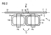
- FIGS. 1 and 2 each show in the direction of the view arrows I and II a patient table 2, on the upper side 4 on a patient, not shown, a magnetically guided capsule endoscopy (MGCE) should be performed.
- MGCE magnetically guided capsule endoscopy
- a coil system 8 is fixedly attached to the underside 6 of the patient table 2.
- the patient table or its table top spans a plane plane 22.
- the coil system 8 comprises a central coil 10 and four coil pairs 12, which each consist of a first single coil 14a and a second single coil 14b.
- the individual coils 14b are in each case inserted into the individual coils 14a.
- the central coil 10 is a Hy coil with respect to the orientation of a coordinate system 16, i. whose normal direction points in the y-direction.
- the individual coils 14a are Hz coils, the individual coils 14b Hx coils.
- the coils 14a are inserted into the coils 14b.
- all individual coils 14a, b and the central coil 10 each have a rectangular shape, which is particularly in Fig. 1 for the central coil 10 and in Fig. 2 for the two illustrated individual coils 14b can be seen.
- Fig. 2 the rectangular shape is symbolized by the line of the rectangle 18 for the single coil 14b.
- All coils are designed as so-called Racetrackspulen, i. they are flat and designed with an aluminum or copper band winding.
- the coil dimensions below refer to a copper coil - which does not necessarily have to be a ribbon coil - with an assumed fill factor including cooling of 85%.
- the outer dimensions of the central coil 10 in the x and z directions is approximately 60cm each.
- the wrapping package has a width of about 10cm in the y-direction to 7.5cm in the x- or z-direction.
- the individual coils 14a, b have a winding cross-section of about 25cm to 9cm, the outer dimensions of the individual coils 14a are in this case about 80 to 100cm in the y-direction and about 80cm in the x-direction.
- the outer dimensions of the individual coils 14b are about 60 to 80cm in the y-direction and about 80cm in the z-direction.
- Fig. 1 It can be seen how the coil pairs 12 are cross-shaped, indicated by the cross 20, with respect to the plane plane 22 around the central coil 10 around grouped. In this case, the cross 20 meets the respective corners of the central coil 10. In the region of the patient table 2, the respective most proximate, ie uppermost sections of the individual coils 14a, b run parallel to one side of the central coil 10.
- both the central coil 10 is parallel to the plane plane 22 and the respective upper portions 24 of the individual coils 14a, b which are closest to the patient table, each parallel to the plane plane 22.
Abstract
Description
Die Erfindung betrifft ein Spulensystem, mit dessen Hilfe eine magnetisch geführte Kapselendoskopie an einem Patienten durchführbar ist.The invention relates to a coil system, by means of which a magnetically guided capsule endoscopy on a patient is feasible.
Bei der magnetisch geführten Kapselendoskopie (MGCE) wird eine Endoskopiekapsel, welche verschiedene medizinische Aufgaben erfüllen kann, in einen Patienten eingebracht. Die Kapsel enthält ein magnetisches Element, mittels dessen durch Anlegen eines äußeren Magnetfeldes eine Kraft bzw. Drehmoment auf die Kapsel ausgeübt werden kann. Durch gezielte Krafteinwirkung kann die Kapsel im Patienten berührungslos fortbewegt werden und dort entsprechend medizinische Aufgaben erfüllen.Magnetic guided capsule endoscopy (MGCE) introduces an endoscopy capsule that can perform various medical tasks into a patient. The capsule contains a magnetic element, by means of which by applying an external magnetic field, a force or torque can be exerted on the capsule. Through targeted application of force, the capsule can be moved without contact in the patient and there correspondingly fulfill medical tasks.
Das äußere Magnetfeld zur Kraftausübung auf die Kapsel wird von einem außerhalb des Patienten angeordneten sogenannten Führungsmagneten (Guidance Magnet) erzeugt. Ein entsprechendes Spulensystem ist z.B. aus der
Die vorliegende Erfindung befasst sich mit einer speziellen Anwendung der MGCE, nämlich der Ösophagus-Gaster-Duodenum(deutsch:ÖGD/englisch:EGD)-Endoskopie, bei welcher eben lediglich Speiseröhre und Magen und gegebenenfalls auch der Zwölffingerdarm eines Patienten mit Hilfe der Kapselendoskopie erreichbar sind.The present invention is concerned with a specific application of MGCE, namely the esophageal gaster duodenum (German: ÖGD / English: EGD) endoscopy, in which just only the esophagus and stomach and possibly also the duodenum of a patient can be reached with the help of capsule endoscopy are.
Für eine derartige ÖGD-Untersuchung wird der Magen z.B. zur Hälfte oder mehr mit Wasser gefüllt. Die Kapsel hat ein Volumen von ca. 2-3cm3. Die Endoskopiekapsel mit einer Masse von ca. 2-3g wird mit einer entsprechenden Dichte ausgeführt, welche nahe, bevorzugt knapp unterhalb der von Wasser ist. Die Endoskopiekapsel schwimmt dann im Magen im Wasser und hat dabei zusammen mit ihrem Auftrieb eine effektive Masse von z.B. -0,1g. Die Einbauten in der Kapsel sind so angeordnet, dass sich der Schwerpunkt der Kapsel auf der Kapsellängsachse ein Stück entfernt vom Kapselmittelpunkt befindet. Die länglich geformte Kapsel steht daher im Wasser ohne äußere Krafteinwirkung senkrecht, deren an der Spitze eingebaute Kamera weist im Ruhezustand nach unten.For such an ÖGD examination, the stomach is filled eg half or more with water. The capsule has a volume of about 2-3cm 3 . The endoscopy capsule with a mass of about 2-3 g is performed with a corresponding density, which is close, preferably just below that of water. The endoscopy capsule then floats in the stomach in the water and, together with its buoyancy, has an effective mass of, for example, -0.1 g. The internals in the capsule are arranged so that the center of gravity of the capsule on the capsule longitudinal axis located a short distance from the center of the capsule. The elongated shaped capsule is therefore vertically in the water without external force, the built-in tip of the camera has at rest down.
Durch einen entsprechenden Führungsmagneten kann die Kapsel gegen deren Auftrieb im Magen von der Wasseroberfläche nach unten gezogen werden, horizontal verfahren und gekippt werden. Bei dieser entsprechenden Spezialanwendung der MGCE sind nur wesentlich geringere Kräfte auf die Kapsel auszuüben, als wenn diese durch den gesamten Intestinaltrakt des Patienten bewegt werden soll.By a corresponding guide magnet, the capsule can be pulled down against the buoyancy in the stomach of the water surface, moved horizontally and tilted. In this particular special application of the MGCE, only much lower forces are exerted on the capsule than if it is to be moved through the entire intestinal tract of the patient.
Im Vergleich zum oben genannten allgemeinen Spulensystem wird für die vorliegende ÖGD-Anwendung daher nur ein sogenannter ÖGD-Führungsmagnet (englisch:EGD Guidance Magnet) verwendet, welcher wesentlich einfacher aufgebaut sein kann als der in der
Darüber hinaus ist aus der
In der
Die Aufgabe wird gelöst durch ein Spulensystem gemäß Patentanspruch 1, welches zur Erzeugung der Magnetfelder für eine magnetisch geführte Kapselendoskopie dient. Das Spulensystem weist folgende Komponenten auf, wobei sämtliche Komponenten unter, d.h. an der Unterseite eines Patiententisches angeordnet sind, wobei auf der Oberseite ein Patient lagerbar ist. Die Platte des Patiententisches definiert hierbei eine - in der Regel horizontale - Planebene, muss aber selbst nicht plan sein. Die Planebene kann z.B. über die Außenlängskanten des Patiententisches definiert sein.The object is achieved by a coil system according to claim 1, which serves to generate the magnetic fields for a magnetically guided capsule endoscopy. The coil system has the following components, with all components below, i. are arranged on the underside of a patient table, wherein on the top of a patient is storable. The plate of the patient table defines this - usually horizontal - Plane level, but does not have to be even plan. The plane plane may e.g. be defined over the outer longitudinal edges of the patient table.
Das Spulensystem umfasst eine Zentralspule, deren Normalenrichtung senkrecht zur Planebene steht. Mit anderen Worten ist die Zentralspule parallel unterhalb des Patiententisches angeordnet. Das Spulensystem weist außerdem vier ebenfalls unter dem Tisch angeordnete Spulenpaare auf, welche kreuzweise um die zentrale Spule herum angeordnet sind. Jedes Spulenpaar umfasst zwei Einzelspulen, deren Normalenrichtungen parallel zur Planebene verlaufen und zusätzlich zueinander um 90° versetzt orientiert sind. Mit anderen Worten bestehen die Spulenpaare also aus gekreuzten, jeweils senkrecht zur Zentralspule stehenden Einzelspulen. Die Zentralspule und ein Spulenpaar stehen damit paarweise aufeinander senkrecht und decken damit alle Raumrichtungen für magentische Felder ab. Oberhalb und seitlich des Patiententisches befinden sich keine Spulen.The coil system comprises a central coil whose normal direction is perpendicular to the plane Plane. In other words, the central coil is arranged parallel below the patient table. The coil system also has four coil pairs also arranged under the table, which are arranged crosswise around the central coil. Each coil pair comprises two individual coils whose normal directions are parallel to the plane of the plane and are additionally oriented offset by 90 ° relative to one another. In other words, the coil pairs thus consist of crossed, each perpendicular to the central coil individual coils. The central coil and a coil pair are thus perpendicular to each other in pairs and thus cover all spatial directions for magenta fields. There are no coils above and at the side of the patient table.
Zur Erläuterung sei ein kartesisches Koordinatensystem (x,y,z) angenommen: Der Patiententisch liegt mit seiner horizontalen Planebene in der (x,z)-Ebene des Koordinatensystems. Die y-Richtung bildet die Vertikale und also die Flächennormale am Patiententisch. Die Zentralspule ist dann auch in y-Richtung orientiert, d.h. die Flächennormale der von der Spule umgespannten Ebene zeigt in y-Richtung. Die Einzelspulen der Spulenpaare sind entsprechend jeweils in x- und z-Richtung orientiert.For explanation, assume a Cartesian coordinate system (x, y, z): The patient table lies with its horizontal plane plane in the (x, z) plane of the coordinate system. The y-direction forms the vertical and thus the surface normal at the patient table. The central coil is then oriented in the y-direction, ie, the surface normal of the spanned by the coil level shows in the y-direction. The individual coils of the coil pairs are respectively oriented in the x and z directions.
Die Erfindung besteht damit in der Idee bzw. Konzeption der Spulengeometrie und -anordnung. Es ergibt sich eine maximale Patientenzugänglichkeit während einer Untersuchung bzw. Prozedur, welche am Patienten auszuführen ist, weil der Magnet, also das gesamte Spulensystem, vollständig unter der Patientenliege angeordnet bzw. "versteckt" ist. Das erfindungsgemäße Spulensystem umfasst nur neun Spulen im Gegensatz zu 10 oder 12 Spulen der bekannten Systeme. Im Gegensatz zum o.g. bekannten Konzept des Blockmagneten ist das Spulensystem starr angeordnet, d.h. der Guidance Magnet enthält keine mechanisch beweglichen Teile.The invention thus consists in the idea or conception of the coil geometry and arrangement. This results in a maximum patient accessibility during an examination or procedure which is to be performed on the patient because the magnet, ie the entire coil system, is completely arranged or "hidden" under the patient bed. The coil system according to the invention comprises only nine coils in contrast to 10 or 12 coils of the known systems. In contrast to the o.g. known concept of the block magnet, the coil system is rigidly arranged, i. The Guidance Magnet contains no mechanical moving parts.
Gegenüber einem System, welches den Patienten umschließt müssen allerdings Verstärker höherer maximaler Stromstärke und Leistung von ca. 350A bzw. 40kW im Vergleich zu 90A bzw. 10kW für die Spulen eingesetzt werden.However, compared to a system that encloses the patient, amplifiers of higher maximum amperage and power of approximately 350A and 40kW, respectively, must be used in comparison to 90A or 10kW for the coils.
Jede Einzelspule eines Spulenpaares weist einen Abschnitt auf, welcher der Planebene am nächsten gelegen ist, also sich nächstliegend an der Planebene befindet. In einer bevorzugten Ausführungsform der Erfindung verläuft dieser Abschnitt parallel zur Planebene. Die Einzelspule weist somit zumindest einen planen Abschnitt auf, der möglichst nahe am Patiententisch angeordnet ist und somit ein möglichst starkes Feld im Bereich des Patienten erzeugen kann. Die restlichen Spulenteile entfernen sich von der Planebene bzw. dem Patiententisch, und deren Feldanteile treten an der Oberseite des Patiententisches in den Hintergrund.Each individual coil of a coil pair has a section which is closest to the plane of the plane, that is, is located closest to the plane of the plane. In a preferred embodiment of the invention, this section is parallel to the plane Plane. The individual coil thus has at least one planar section, which is arranged as close as possible to the patient table and thus can generate the strongest possible field in the region of the patient. The remaining coil parts move away from the plane plane or the patient table, and their field shares occur at the top of the patient table in the background.
In einer weiteren bevorzugten Ausführungsform weisen die Zentralspule und/oder die Einzelspulen eine rechteckige Form mit abgerundeten Ecken auf. Die Wicklung der Spulen verläuft also entlang einer Kurve, die annähernd ein Rechteck beschreibt bzw. die von der Wicklung umgrenzte Fläche ist annähernd rechteckig. Insbesondere für die Einzelspulen verfügen diese dann über eine Seiten, also einen Abschnitt, welche nächstliegend der Planebene bzw. Patientenliege angeordnet ist und parallel zu dieser verläuft. An diesen Abschnitt schließen sich dann die beiden senkrecht hierzu verlaufenden Seiten des Rechtecks an, welche jedoch wegen des 90° Winkels im Rechteck um 90° versetzte Feldkomponenten erzeugen. Die vierte Seite des Rechteckes ist dann von der Planebene möglichst weit entfernt, um das vom ersten Abschnitt erzeugte Feld praktisch nur noch geringfügig zu schwächen.In a further preferred embodiment, the central coil and / or the individual coils have a rectangular shape with rounded corners. The winding of the coils thus runs along a curve which describes approximately a rectangle or the area delimited by the winding is approximately rectangular. In particular for the individual coils, these then have one side, that is to say a section which is arranged closest to the plane plane or patient couch and runs parallel to it. At this section then join the two perpendicular to this extending sides of the rectangle, but which generate because of the 90 ° angle in the rectangle by 90 ° offset field components. The fourth side of the rectangle is then as far as possible from the plane Plane, in order to weaken the field generated by the first section practically only slightly.
Bei der Ausführung der Zentralspule als Rechteck oder Quadrat können insbesondere die vier Spulenpaare kreuzweise an den Ecken der Zentralspule angeordnet sein. Die Einzelspulen sind dann parallel zu den jeweiligen Seiten der rechteckigen Zentralspule ausgerichtet.In the embodiment of the central coil as a rectangle or square, in particular, the four coil pairs can be arranged crosswise at the corners of the central coil. The individual coils are then aligned parallel to the respective sides of the rectangular central coil.
In einer weiteren bevorzugten Ausführungsform der Erfindung ist die jeweils eine Einzelspule eines Spulenpaares in die jeweils andere Einzelspule eingesteckt. Die Herstellung des Spulenpaares ist dadurch besonders einfach möglich, da keine Überkreuzung der Wicklungen nötig ist.In a further preferred embodiment of the invention, the respective one individual coil of a coil pair is inserted into the respective other individual coil. The production of the coil pair is particularly easy because no crossover of the windings is necessary.
In einer weiteren vorteilhaften Ausführungsform der Erfindung weisen alle Spulenpaare gleich Ausrichtung auf. Mit obiger Nomenklatur einer in y-Richtung orientierten Zentralspule sind dann beispielsweise sämtliche erste Spulen der vier Spulenpaare in x-Richtung und sämtliche zweiten Spulen der vier Spulenpaare in z-Richtung ausgerichtet. So entsteht eine äußert symmetrische Anordnung.In a further advantageous embodiment of the invention, all coil pairs have the same orientation. With the above nomenclature of a center coil oriented in the y direction, all the first coils of the four coil pairs are then aligned in the x direction and all the second coils of the four coil pairs are aligned in the z direction, for example. This creates an extremely symmetrical arrangement.
In einer weiteren bevorzugten Ausführungsform ist die Zentralspule und/oder die Einzelspule eine Racetrackspule. Racetrackspulen sind eben und können beispielsweise als Aluminium oder Kupferbandwicklung ausgeführt werden.In a further preferred embodiment, the central coil and / or the individual coil is a racetrack coil. Racetrack coils are flat and can be made, for example, as aluminum or copper tape winding.
In einer bevorzugten Variante weist daher die Racetrackspule eine Bandwicklung auf.In a preferred variant, therefore, the Racetrackspule on a tape winding.
In einer bevorzugten Ausführungsform erfolgt eine Kühlung der Bandwicklung an einer oder an beiden Seitenflächen der Bandwicklung. Bei einseitiger Kühlung erfolgt die Kühlung an derjenigen Seite der Bandwicklung, so dass sich ein möglichst kompaktes Design der Spulenanordnung bei größtmöglicher Nähe zum Arbeitsvolumen ergibt.In a preferred embodiment, the tape winding is cooled on one or both side surfaces of the tape winding. With one-sided cooling, the cooling takes place at that Side of the tape winding, so that the most compact possible design of the coil assembly results in the greatest possible proximity to the working volume.
Für eine weitere Beschreibung der Erfindung wird auf die Ausführungsbeispiele der Zeichnungen verwiesen. Es zeigen, jeweils in einer schematischen Prinzipskizze:
- Fig. 1
- einen Patiententisch mit erfindungsgemäßem Spulensystem in Draufsicht,
- Fig. 2
- das Spulensystem in
Fig. 1 .in Richtung des Pfeils II.
- Fig. 1
- a patient table with inventive coil system in plan view,
- Fig. 2
- the coil system in
Fig. 1 in the direction of arrow II.
Die
Das Spulensystem 8 umfasst eine Zentralspule 10 sowie vier Spulenpaare 12, welche jeweils aus einer ersten Einzelspule 14a und einer zweiten Einzelspule 14b bestehen. Die Einzelspulen 14b sind hierbei jeweils in die Einzelspulen 14a eingesteckt. Die Zentralspule 10 ist bezüglich der Orientierung eines Koordinatensystems 16 eine Hy-Spule, d.h. deren Normalenrichtung zeigt in y-Richtung. Die Einzelspulen 14a sind Hz-Spulen, die Einzelspulen 14b Hx-Spulen.The
In einer alternativen, nicht dargestellten Ausführungsform sind die Spulen 14a in die Spulen 14b eingesteckt. Im Ausführungsbeispiel weisen sämtliche Einzelspulen 14a,b sowie die Zentralspule 10 jeweils rechteckige Form auf, was insbesondere in
Alle Spulen sind als sogenannte Racetrackspulen ausgeführt, d.h. sie sind eben und mit einer Aluminium- oder Kupferbandwicklung ausgeführt. Die im Folgenden angegebenen Spulenabmessungen beziehen sich auf eine Kupferwicklung - welche nicht notwendigerweise eine Bandwicklung sein muss - mit einem angenommenen Füllfaktor einschließlich Kühlung von 85%. Die Außenabmessungen der Zentralspule 10 in x- und z-Richtung beträgt jeweils ca. 60cm. Das Wickelpaket hat eine Breite von ca. 10cm in y-Richtung auf 7,5cm in x- bzw. z-Richtung.All coils are designed as so-called Racetrackspulen, i. they are flat and designed with an aluminum or copper band winding. The coil dimensions below refer to a copper coil - which does not necessarily have to be a ribbon coil - with an assumed fill factor including cooling of 85%. The outer dimensions of the
Die Einzelspulen 14a,b haben einen Wicklungsquerschnitt von ca. 25cm auf 9cm, die Außenabmessungen der Einzelspulen 14a sind hierbei ca. 80 bis 100cm in y-Richtung und ca. 80cm in x-Richtung. Die Außenabmessungen der Einzelspulen 14b sind ca. 60 bis 80cm in y-Richtung und ca. 80cm in z-Richtung.The
In
In
Claims (8)
- Solenoid system (8) for magnetically guided capsule endoscopy, comprising a patient table (2) defining a flat plane (22) and the following components arranged under the patient table (2):- a central coil (10) with a normal direction (y) perpendicular to the flat plane (22),- four coil pairs (12), which, in respect of the flat plane (22), are arranged around the central coil (10) to form a cross (20) and which respectively comprise two single coils (14a, b), the normal directions (z, x) of which are oriented parallel to the flat plane (22) and offset by 90° with respect to one another.
- Solenoid system (8) according to Claim 1, in which the single coil (14a, b) has a section (24), closest to the flat plane (22), which runs parallel to the flat plane (22).
- Solenoid system (8) according to one of the preceding claims, in which the central coil (10) and/or the single coil (14a, b) has the shape of a rectangle (18).
- Solenoid system (8) according to one of the preceding claims, in which the one single coil (14b) of a coil pair (12) is inserted into the other single coil (14a).
- Solenoid system (8) according to one of the preceding claims, in which all coil pairs (12) have the same alignment (z, x).
- Solenoid system (8) according to one of the preceding claims, in which the central coil (10) and/or the single coil (14a, b) is a racetrack coil.
- Solenoid system (8) according to Claim 6, in which the racetrack coil has a strip winding.
- Solenoid system (8) according to Claim 7, in which the strip winding is cooled on one or on both lateral sides of the strip winding.
Applications Claiming Priority (2)
| Application Number | Priority Date | Filing Date | Title |
|---|---|---|---|
| DE102009039484A DE102009039484A1 (en) | 2009-08-31 | 2009-08-31 | Coil system for a magnetically guided capsule endoscopy |
| PCT/EP2010/062365 WO2011023710A1 (en) | 2009-08-31 | 2010-08-25 | Solenoid system for magnetically guided capsule endoscopy |
Publications (2)
| Publication Number | Publication Date |
|---|---|
| EP2473129A1 EP2473129A1 (en) | 2012-07-11 |
| EP2473129B1 true EP2473129B1 (en) | 2013-11-20 |
Family
ID=43416551
Family Applications (1)
| Application Number | Title | Priority Date | Filing Date |
|---|---|---|---|
| EP10757177.0A Not-in-force EP2473129B1 (en) | 2009-08-31 | 2010-08-25 | Solenoid system for magnetically guided capsule endoscopy |
Country Status (7)
| Country | Link |
|---|---|
| US (1) | US9283044B2 (en) |
| EP (1) | EP2473129B1 (en) |
| JP (1) | JP5506930B2 (en) |
| KR (1) | KR101314484B1 (en) |
| CN (1) | CN102481174B (en) |
| DE (1) | DE102009039484A1 (en) |
| WO (1) | WO2011023710A1 (en) |
Families Citing this family (6)
| Publication number | Priority date | Publication date | Assignee | Title |
|---|---|---|---|---|
| DE102009039484A1 (en) | 2009-08-31 | 2011-03-03 | Siemens Aktiengesellschaft | Coil system for a magnetically guided capsule endoscopy |
| US10199147B2 (en) * | 2012-10-18 | 2019-02-05 | University Of Utah Research Foundation | Omnidirectional electromagnet |
| JP6376847B2 (en) * | 2014-05-31 | 2018-08-22 | 株式会社ミュー | Medical equipment |
| KR102260162B1 (en) * | 2019-10-21 | 2021-06-03 | 전남대학교산학협력단 | Apparatus for Controlling Micro Robot |
| US11883007B2 (en) | 2021-08-07 | 2024-01-30 | Brian Michael Coyle | Controlled motion capsule |
| KR102436113B1 (en) * | 2021-11-02 | 2022-08-25 | 주식회사 아임시스템 | Magnetic field generator for precision procedure |
Family Cites Families (17)
| Publication number | Priority date | Publication date | Assignee | Title |
|---|---|---|---|---|
| GB1035205A (en) | 1962-11-30 | 1966-07-06 | Yeda Res & Dev | Improvements in the remote controlled propulsion of a body |
| US5592939A (en) * | 1995-06-14 | 1997-01-14 | Martinelli; Michael A. | Method and system for navigating a catheter probe |
| AU1240801A (en) * | 1999-10-28 | 2001-05-08 | Enterprise Medical Technology, Inc. | Coil structures and methods for generating magnetic fields |
| US6493573B1 (en) * | 1999-10-28 | 2002-12-10 | Winchester Development Associates | Method and system for navigating a catheter probe in the presence of field-influencing objects |
| GB0031287D0 (en) * | 2000-12-21 | 2001-01-31 | Oxford Instr Ltd | Magnetic field generating system and method |
| US7224252B2 (en) * | 2003-06-06 | 2007-05-29 | Magno Corporation | Adaptive magnetic levitation apparatus and method |
| DE10340925B3 (en) * | 2003-09-05 | 2005-06-30 | Siemens Ag | Magnetic coil system for non-contact movement of a magnetic body in a working space |
| US7751866B2 (en) | 2004-03-08 | 2010-07-06 | Olympus Corporation | Detecting system of position and posture of capsule medical device |
| JP4426875B2 (en) | 2004-03-08 | 2010-03-03 | オリンパス株式会社 | Capsule medical device magnetic guidance system |
| JP4709594B2 (en) * | 2004-08-03 | 2011-06-22 | オリンパス株式会社 | Magnetic guidance medical system |
| KR101092867B1 (en) * | 2005-12-28 | 2011-12-14 | 올림푸스 메디칼 시스템즈 가부시키가이샤 | Into-examinee observation apparatus |
| DE102007007801B4 (en) | 2007-02-16 | 2015-02-26 | Siemens Aktiengesellschaft | Magnetic coil system with a navigation coil system and a location system |
| JP4668967B2 (en) | 2007-09-26 | 2011-04-13 | オリンパス株式会社 | Capsule type medical device direction detection system |
| DE102008004871B4 (en) | 2008-01-17 | 2013-05-16 | Siemens Aktiengesellschaft | Coil arrangement for guiding a magnetic element in a working space |
| US8235888B2 (en) * | 2008-07-08 | 2012-08-07 | Olympus Medical Systems Corp. | System for guiding capsule medical device |
| DE102009039484A1 (en) | 2009-08-31 | 2011-03-03 | Siemens Aktiengesellschaft | Coil system for a magnetically guided capsule endoscopy |
| CN102665530B (en) * | 2010-03-26 | 2014-11-26 | 奥林巴斯医疗株式会社 | Capsule medical device guidance system and method for guiding capsule medical device |
-
2009
- 2009-08-31 DE DE102009039484A patent/DE102009039484A1/en not_active Withdrawn
-
2010
- 2010-08-25 JP JP2012526043A patent/JP5506930B2/en not_active Expired - Fee Related
- 2010-08-25 WO PCT/EP2010/062365 patent/WO2011023710A1/en active Application Filing
- 2010-08-25 KR KR1020127008353A patent/KR101314484B1/en active IP Right Grant
- 2010-08-25 EP EP10757177.0A patent/EP2473129B1/en not_active Not-in-force
- 2010-08-25 CN CN201080038717.5A patent/CN102481174B/en not_active Expired - Fee Related
- 2010-08-25 US US13/393,417 patent/US9283044B2/en not_active Expired - Fee Related
Also Published As
| Publication number | Publication date |
|---|---|
| US20120232337A1 (en) | 2012-09-13 |
| JP2013502953A (en) | 2013-01-31 |
| CN102481174B (en) | 2015-04-08 |
| KR101314484B1 (en) | 2013-10-07 |
| WO2011023710A1 (en) | 2011-03-03 |
| DE102009039484A8 (en) | 2011-06-01 |
| EP2473129A1 (en) | 2012-07-11 |
| DE102009039484A1 (en) | 2011-03-03 |
| JP5506930B2 (en) | 2014-05-28 |
| KR20120062858A (en) | 2012-06-14 |
| US9283044B2 (en) | 2016-03-15 |
| CN102481174A (en) | 2012-05-30 |
Similar Documents
| Publication | Publication Date | Title |
|---|---|---|
| EP2473129B1 (en) | Solenoid system for magnetically guided capsule endoscopy | |
| DE10340925B3 (en) | Magnetic coil system for non-contact movement of a magnetic body in a working space | |
| DE102005010489B4 (en) | Coil system for non-contact magnetic navigation of a magnetic body in a patient located in a working space | |
| DE10241178B4 (en) | Isokinetic gantry arrangement for the isocentric guidance of a particle beam and method for its design | |
| DE102008004871B4 (en) | Coil arrangement for guiding a magnetic element in a working space | |
| DE4422782C2 (en) | Actively shielded transverse gradient coil for magnetic resonance imaging devices | |
| EP1988552A1 (en) | Beam guidance magnet for guiding a beam of electrically charged particles along a curved particle pathway and beam assembly with such a magnet | |
| DE102008007245A1 (en) | Combined radiotherapy and magnetic resonance device | |
| DE102008019380A1 (en) | Bipolar clamp for HF surgery | |
| DE10341092A1 (en) | Non-contact type probe device used in medical surgery, has fourteen coils for generating three magnetic field component and five magnetic field gradient from the diagonally symmetrical gradient matrices | |
| DE102009013352B4 (en) | Coil arrangements for guiding a magnetic object in a working space | |
| DE102018114905A1 (en) | INTEGRATED MAGNETIC ASSEMBLIES AND METHOD FOR ASSEMBLING THEM | |
| DE102008030833A1 (en) | Patient bedding device for use during treatment of patient in tube of e.g. computer tomography device, has rotating device mounted at retaining plate in bearing at rotating axis that is oriented parallel to longitudinal axis of stretcher | |
| DE102018215457A1 (en) | Customizable MR local coil | |
| DE102007046508A1 (en) | Irradiation plant with a beam guiding magnet | |
| DE2029005A1 (en) | Arrangement for radiation especially neutron radiation therapy | |
| DE102008064379A1 (en) | Magnetic coil arrangement with fixed and movable coils | |
| DE102013013633A1 (en) | Electrical terminal for use in high current applications, has spring head that is in contact with arms toward distal end of contact portion for applying force in direction toward central axis of contact portion | |
| DE1008817B (en) | Rectangular magnetic core made of laminated sheet metal for electrical induction devices, especially transformers | |
| DE10160610B4 (en) | Filters for an X-ray examination device for absorbing X-rays and medical X-ray device with such a filter | |
| DE102011004825A1 (en) | Method and device for controlling the transport of a magnetic moment endoscope capsule | |
| DE102005060834A1 (en) | Magnetic field | |
| DE202012100245U1 (en) | Device for generating magnetic fields for magnetic field therapy | |
| DE3010674C2 (en) | Ribbon conductor for the formation of poles for a dipole or multipole which is used to deflect and / or focus particle beams and can be operated in pulsed mode | |
| DE102010012073B4 (en) | Device for reducing the heating of a vacuum chamber |
Legal Events
| Date | Code | Title | Description |
|---|---|---|---|
| PUAI | Public reference made under article 153(3) epc to a published international application that has entered the european phase |
Free format text: ORIGINAL CODE: 0009012 |
|
| 17P | Request for examination filed |
Effective date: 20120223 |
|
| AK | Designated contracting states |
Kind code of ref document: A1 Designated state(s): AL AT BE BG CH CY CZ DE DK EE ES FI FR GB GR HR HU IE IS IT LI LT LU LV MC MK MT NL NO PL PT RO SE SI SK SM TR |
|
| DAX | Request for extension of the european patent (deleted) | ||
| RAP1 | Party data changed (applicant data changed or rights of an application transferred) |
Owner name: SIEMENS AKTIENGESELLSCHAFT |
|
| GRAP | Despatch of communication of intention to grant a patent |
Free format text: ORIGINAL CODE: EPIDOSNIGR1 |
|
| INTG | Intention to grant announced |
Effective date: 20130517 |
|
| GRAP | Despatch of communication of intention to grant a patent |
Free format text: ORIGINAL CODE: EPIDOSNIGR1 |
|
| INTG | Intention to grant announced |
Effective date: 20130621 |
|
| GRAS | Grant fee paid |
Free format text: ORIGINAL CODE: EPIDOSNIGR3 |
|
| GRAA | (expected) grant |
Free format text: ORIGINAL CODE: 0009210 |
|
| AK | Designated contracting states |
Kind code of ref document: B1 Designated state(s): AL AT BE BG CH CY CZ DE DK EE ES FI FR GB GR HR HU IE IS IT LI LT LU LV MC MK MT NL NO PL PT RO SE SI SK SM TR |
|
| REG | Reference to a national code |
Ref country code: GB Ref legal event code: FG4D Free format text: NOT ENGLISH |
|
| REG | Reference to a national code |
Ref country code: CH Ref legal event code: EP |
|
| REG | Reference to a national code |
Ref country code: AT Ref legal event code: REF Ref document number: 641107 Country of ref document: AT Kind code of ref document: T Effective date: 20131215 |
|
| REG | Reference to a national code |
Ref country code: IE Ref legal event code: FG4D Free format text: LANGUAGE OF EP DOCUMENT: GERMAN |
|
| REG | Reference to a national code |
Ref country code: DE Ref legal event code: R096 Ref document number: 502010005438 Country of ref document: DE Effective date: 20140116 |
|
| REG | Reference to a national code |
Ref country code: NL Ref legal event code: VDEP Effective date: 20131120 |
|
| REG | Reference to a national code |
Ref country code: LT Ref legal event code: MG4D |
|
| PG25 | Lapsed in a contracting state [announced via postgrant information from national office to epo] |
Ref country code: IS Free format text: LAPSE BECAUSE OF FAILURE TO SUBMIT A TRANSLATION OF THE DESCRIPTION OR TO PAY THE FEE WITHIN THE PRESCRIBED TIME-LIMIT Effective date: 20140320 Ref country code: NL Free format text: LAPSE BECAUSE OF FAILURE TO SUBMIT A TRANSLATION OF THE DESCRIPTION OR TO PAY THE FEE WITHIN THE PRESCRIBED TIME-LIMIT Effective date: 20131120 Ref country code: SE Free format text: LAPSE BECAUSE OF FAILURE TO SUBMIT A TRANSLATION OF THE DESCRIPTION OR TO PAY THE FEE WITHIN THE PRESCRIBED TIME-LIMIT Effective date: 20131120 Ref country code: NO Free format text: LAPSE BECAUSE OF FAILURE TO SUBMIT A TRANSLATION OF THE DESCRIPTION OR TO PAY THE FEE WITHIN THE PRESCRIBED TIME-LIMIT Effective date: 20140220 Ref country code: FI Free format text: LAPSE BECAUSE OF FAILURE TO SUBMIT A TRANSLATION OF THE DESCRIPTION OR TO PAY THE FEE WITHIN THE PRESCRIBED TIME-LIMIT Effective date: 20131120 Ref country code: LT Free format text: LAPSE BECAUSE OF FAILURE TO SUBMIT A TRANSLATION OF THE DESCRIPTION OR TO PAY THE FEE WITHIN THE PRESCRIBED TIME-LIMIT Effective date: 20131120 Ref country code: HR Free format text: LAPSE BECAUSE OF FAILURE TO SUBMIT A TRANSLATION OF THE DESCRIPTION OR TO PAY THE FEE WITHIN THE PRESCRIBED TIME-LIMIT Effective date: 20131120 |
|
| PG25 | Lapsed in a contracting state [announced via postgrant information from national office to epo] |
Ref country code: ES Free format text: LAPSE BECAUSE OF FAILURE TO SUBMIT A TRANSLATION OF THE DESCRIPTION OR TO PAY THE FEE WITHIN THE PRESCRIBED TIME-LIMIT Effective date: 20131120 Ref country code: LV Free format text: LAPSE BECAUSE OF FAILURE TO SUBMIT A TRANSLATION OF THE DESCRIPTION OR TO PAY THE FEE WITHIN THE PRESCRIBED TIME-LIMIT Effective date: 20131120 |
|
| PG25 | Lapsed in a contracting state [announced via postgrant information from national office to epo] |
Ref country code: PT Free format text: LAPSE BECAUSE OF FAILURE TO SUBMIT A TRANSLATION OF THE DESCRIPTION OR TO PAY THE FEE WITHIN THE PRESCRIBED TIME-LIMIT Effective date: 20140320 |
|
| PG25 | Lapsed in a contracting state [announced via postgrant information from national office to epo] |
Ref country code: EE Free format text: LAPSE BECAUSE OF FAILURE TO SUBMIT A TRANSLATION OF THE DESCRIPTION OR TO PAY THE FEE WITHIN THE PRESCRIBED TIME-LIMIT Effective date: 20131120 |
|
| REG | Reference to a national code |
Ref country code: DE Ref legal event code: R097 Ref document number: 502010005438 Country of ref document: DE |
|
| PG25 | Lapsed in a contracting state [announced via postgrant information from national office to epo] |
Ref country code: SK Free format text: LAPSE BECAUSE OF FAILURE TO SUBMIT A TRANSLATION OF THE DESCRIPTION OR TO PAY THE FEE WITHIN THE PRESCRIBED TIME-LIMIT Effective date: 20131120 Ref country code: RO Free format text: LAPSE BECAUSE OF FAILURE TO SUBMIT A TRANSLATION OF THE DESCRIPTION OR TO PAY THE FEE WITHIN THE PRESCRIBED TIME-LIMIT Effective date: 20131120 Ref country code: CZ Free format text: LAPSE BECAUSE OF FAILURE TO SUBMIT A TRANSLATION OF THE DESCRIPTION OR TO PAY THE FEE WITHIN THE PRESCRIBED TIME-LIMIT Effective date: 20131120 Ref country code: PL Free format text: LAPSE BECAUSE OF FAILURE TO SUBMIT A TRANSLATION OF THE DESCRIPTION OR TO PAY THE FEE WITHIN THE PRESCRIBED TIME-LIMIT Effective date: 20131120 |
|
| PLBE | No opposition filed within time limit |
Free format text: ORIGINAL CODE: 0009261 |
|
| STAA | Information on the status of an ep patent application or granted ep patent |
Free format text: STATUS: NO OPPOSITION FILED WITHIN TIME LIMIT |
|
| PG25 | Lapsed in a contracting state [announced via postgrant information from national office to epo] |
Ref country code: DK Free format text: LAPSE BECAUSE OF FAILURE TO SUBMIT A TRANSLATION OF THE DESCRIPTION OR TO PAY THE FEE WITHIN THE PRESCRIBED TIME-LIMIT Effective date: 20131120 |
|
| 26N | No opposition filed |
Effective date: 20140821 |
|
| REG | Reference to a national code |
Ref country code: DE Ref legal event code: R097 Ref document number: 502010005438 Country of ref document: DE Effective date: 20140821 |
|
| PG25 | Lapsed in a contracting state [announced via postgrant information from national office to epo] |
Ref country code: SI Free format text: LAPSE BECAUSE OF FAILURE TO SUBMIT A TRANSLATION OF THE DESCRIPTION OR TO PAY THE FEE WITHIN THE PRESCRIBED TIME-LIMIT Effective date: 20131120 |
|
| PG25 | Lapsed in a contracting state [announced via postgrant information from national office to epo] |
Ref country code: LU Free format text: LAPSE BECAUSE OF FAILURE TO SUBMIT A TRANSLATION OF THE DESCRIPTION OR TO PAY THE FEE WITHIN THE PRESCRIBED TIME-LIMIT Effective date: 20140825 Ref country code: MC Free format text: LAPSE BECAUSE OF FAILURE TO SUBMIT A TRANSLATION OF THE DESCRIPTION OR TO PAY THE FEE WITHIN THE PRESCRIBED TIME-LIMIT Effective date: 20131120 |
|
| REG | Reference to a national code |
Ref country code: CH Ref legal event code: PL |
|
| GBPC | Gb: european patent ceased through non-payment of renewal fee |
Effective date: 20140825 |
|
| PG25 | Lapsed in a contracting state [announced via postgrant information from national office to epo] |
Ref country code: LI Free format text: LAPSE BECAUSE OF NON-PAYMENT OF DUE FEES Effective date: 20140831 Ref country code: CH Free format text: LAPSE BECAUSE OF NON-PAYMENT OF DUE FEES Effective date: 20140831 Ref country code: IT Free format text: LAPSE BECAUSE OF FAILURE TO SUBMIT A TRANSLATION OF THE DESCRIPTION OR TO PAY THE FEE WITHIN THE PRESCRIBED TIME-LIMIT Effective date: 20131120 Ref country code: BE Free format text: LAPSE BECAUSE OF NON-PAYMENT OF DUE FEES Effective date: 20140831 |
|
| REG | Reference to a national code |
Ref country code: IE Ref legal event code: MM4A |
|
| REG | Reference to a national code |
Ref country code: FR Ref legal event code: ST Effective date: 20150430 |
|
| PG25 | Lapsed in a contracting state [announced via postgrant information from national office to epo] |
Ref country code: GB Free format text: LAPSE BECAUSE OF NON-PAYMENT OF DUE FEES Effective date: 20140825 |
|
| PG25 | Lapsed in a contracting state [announced via postgrant information from national office to epo] |
Ref country code: IE Free format text: LAPSE BECAUSE OF NON-PAYMENT OF DUE FEES Effective date: 20140825 Ref country code: FR Free format text: LAPSE BECAUSE OF NON-PAYMENT OF DUE FEES Effective date: 20140901 |
|
| PG25 | Lapsed in a contracting state [announced via postgrant information from national office to epo] |
Ref country code: SM Free format text: LAPSE BECAUSE OF FAILURE TO SUBMIT A TRANSLATION OF THE DESCRIPTION OR TO PAY THE FEE WITHIN THE PRESCRIBED TIME-LIMIT Effective date: 20131120 |
|
| REG | Reference to a national code |
Ref country code: DE Ref legal event code: R081 Ref document number: 502010005438 Country of ref document: DE Owner name: INVANDUS GMBH, DE Free format text: FORMER OWNER: SIEMENS AKTIENGESELLSCHAFT, 80333 MUENCHEN, DE Ref country code: DE Ref legal event code: R081 Ref document number: 502010005438 Country of ref document: DE Owner name: SIEMENS HEALTHCARE GMBH, DE Free format text: FORMER OWNER: SIEMENS AKTIENGESELLSCHAFT, 80333 MUENCHEN, DE |
|
| PG25 | Lapsed in a contracting state [announced via postgrant information from national office to epo] |
Ref country code: MT Free format text: LAPSE BECAUSE OF FAILURE TO SUBMIT A TRANSLATION OF THE DESCRIPTION OR TO PAY THE FEE WITHIN THE PRESCRIBED TIME-LIMIT Effective date: 20131120 Ref country code: GR Free format text: LAPSE BECAUSE OF FAILURE TO SUBMIT A TRANSLATION OF THE DESCRIPTION OR TO PAY THE FEE WITHIN THE PRESCRIBED TIME-LIMIT Effective date: 20140221 Ref country code: CY Free format text: LAPSE BECAUSE OF FAILURE TO SUBMIT A TRANSLATION OF THE DESCRIPTION OR TO PAY THE FEE WITHIN THE PRESCRIBED TIME-LIMIT Effective date: 20131120 Ref country code: BG Free format text: LAPSE BECAUSE OF FAILURE TO SUBMIT A TRANSLATION OF THE DESCRIPTION OR TO PAY THE FEE WITHIN THE PRESCRIBED TIME-LIMIT Effective date: 20131120 |
|
| PG25 | Lapsed in a contracting state [announced via postgrant information from national office to epo] |
Ref country code: HU Free format text: LAPSE BECAUSE OF FAILURE TO SUBMIT A TRANSLATION OF THE DESCRIPTION OR TO PAY THE FEE WITHIN THE PRESCRIBED TIME-LIMIT; INVALID AB INITIO Effective date: 20100825 Ref country code: TR Free format text: LAPSE BECAUSE OF FAILURE TO SUBMIT A TRANSLATION OF THE DESCRIPTION OR TO PAY THE FEE WITHIN THE PRESCRIBED TIME-LIMIT Effective date: 20131120 |
|
| REG | Reference to a national code |
Ref country code: AT Ref legal event code: MM01 Ref document number: 641107 Country of ref document: AT Kind code of ref document: T Effective date: 20150825 |
|
| PG25 | Lapsed in a contracting state [announced via postgrant information from national office to epo] |
Ref country code: AT Free format text: LAPSE BECAUSE OF NON-PAYMENT OF DUE FEES Effective date: 20150825 |
|
| PG25 | Lapsed in a contracting state [announced via postgrant information from national office to epo] |
Ref country code: MK Free format text: LAPSE BECAUSE OF FAILURE TO SUBMIT A TRANSLATION OF THE DESCRIPTION OR TO PAY THE FEE WITHIN THE PRESCRIBED TIME-LIMIT Effective date: 20131120 |
|
| REG | Reference to a national code |
Ref country code: DE Ref legal event code: R081 Ref document number: 502010005438 Country of ref document: DE Owner name: INVANDUS GMBH, DE Free format text: FORMER OWNER: SIEMENS HEALTHCARE GMBH, 91052 ERLANGEN, DE |
|
| PG25 | Lapsed in a contracting state [announced via postgrant information from national office to epo] |
Ref country code: AL Free format text: LAPSE BECAUSE OF FAILURE TO SUBMIT A TRANSLATION OF THE DESCRIPTION OR TO PAY THE FEE WITHIN THE PRESCRIBED TIME-LIMIT Effective date: 20131120 |
|
| PGFP | Annual fee paid to national office [announced via postgrant information from national office to epo] |
Ref country code: DE Payment date: 20211019 Year of fee payment: 12 |
|
| REG | Reference to a national code |
Ref country code: DE Ref legal event code: R081 Ref document number: 502010005438 Country of ref document: DE Owner name: INVANDUS GMBH, DE Free format text: FORMER OWNER: SIEMENS HEALTHCARE GMBH, MUENCHEN, DE |
|
| REG | Reference to a national code |
Ref country code: DE Ref legal event code: R119 Ref document number: 502010005438 Country of ref document: DE |
|
| PG25 | Lapsed in a contracting state [announced via postgrant information from national office to epo] |
Ref country code: DE Free format text: LAPSE BECAUSE OF NON-PAYMENT OF DUE FEES Effective date: 20230301 |