EP2472812A1 - Scalable wireless multicell voip architecture - Google Patents
Scalable wireless multicell voip architecture Download PDFInfo
- Publication number
- EP2472812A1 EP2472812A1 EP10197291A EP10197291A EP2472812A1 EP 2472812 A1 EP2472812 A1 EP 2472812A1 EP 10197291 A EP10197291 A EP 10197291A EP 10197291 A EP10197291 A EP 10197291A EP 2472812 A1 EP2472812 A1 EP 2472812A1
- Authority
- EP
- European Patent Office
- Prior art keywords
- wireless
- base station
- communication
- network
- communication session
- Prior art date
- Legal status (The legal status is an assumption and is not a legal conclusion. Google has not performed a legal analysis and makes no representation as to the accuracy of the status listed.)
- Granted
Links
- 238000004891 communication Methods 0.000 claims abstract description 128
- 238000012545 processing Methods 0.000 claims description 11
- 238000010586 diagram Methods 0.000 description 2
- 238000000034 method Methods 0.000 description 2
- 102100032341 PCNA-interacting partner Human genes 0.000 description 1
- 101710196737 PCNA-interacting partner Proteins 0.000 description 1
- 230000000694 effects Effects 0.000 description 1
- 238000005516 engineering process Methods 0.000 description 1
- 230000002708 enhancing effect Effects 0.000 description 1
- 238000012423 maintenance Methods 0.000 description 1
- 238000013507 mapping Methods 0.000 description 1
- 230000001360 synchronised effect Effects 0.000 description 1
Images


Classifications
-
- H—ELECTRICITY
- H04—ELECTRIC COMMUNICATION TECHNIQUE
- H04W—WIRELESS COMMUNICATION NETWORKS
- H04W36/00—Hand-off or reselection arrangements
- H04W36/24—Reselection being triggered by specific parameters
- H04W36/26—Reselection being triggered by specific parameters by agreed or negotiated communication parameters
- H04W36/28—Reselection being triggered by specific parameters by agreed or negotiated communication parameters involving a plurality of connections, e.g. multi-call or multi-bearer connections
-
- H—ELECTRICITY
- H04—ELECTRIC COMMUNICATION TECHNIQUE
- H04W—WIRELESS COMMUNICATION NETWORKS
- H04W76/00—Connection management
-
- H—ELECTRICITY
- H04—ELECTRIC COMMUNICATION TECHNIQUE
- H04W—WIRELESS COMMUNICATION NETWORKS
- H04W36/00—Hand-off or reselection arrangements
- H04W36/0005—Control or signalling for completing the hand-off
-
- H—ELECTRICITY
- H04—ELECTRIC COMMUNICATION TECHNIQUE
- H04L—TRANSMISSION OF DIGITAL INFORMATION, e.g. TELEGRAPHIC COMMUNICATION
- H04L65/00—Network arrangements, protocols or services for supporting real-time applications in data packet communication
- H04L65/10—Architectures or entities
- H04L65/102—Gateways
- H04L65/1033—Signalling gateways
- H04L65/1036—Signalling gateways at the edge
-
- H—ELECTRICITY
- H04—ELECTRIC COMMUNICATION TECHNIQUE
- H04L—TRANSMISSION OF DIGITAL INFORMATION, e.g. TELEGRAPHIC COMMUNICATION
- H04L65/00—Network arrangements, protocols or services for supporting real-time applications in data packet communication
- H04L65/1066—Session management
- H04L65/1069—Session establishment or de-establishment
-
- H—ELECTRICITY
- H04—ELECTRIC COMMUNICATION TECHNIQUE
- H04W—WIRELESS COMMUNICATION NETWORKS
- H04W36/00—Hand-off or reselection arrangements
- H04W36/0005—Control or signalling for completing the hand-off
- H04W36/0011—Control or signalling for completing the hand-off for data sessions of end-to-end connection
-
- H—ELECTRICITY
- H04—ELECTRIC COMMUNICATION TECHNIQUE
- H04W—WIRELESS COMMUNICATION NETWORKS
- H04W80/00—Wireless network protocols or protocol adaptations to wireless operation
- H04W80/04—Network layer protocols, e.g. mobile IP [Internet Protocol]
-
- H—ELECTRICITY
- H04—ELECTRIC COMMUNICATION TECHNIQUE
- H04W—WIRELESS COMMUNICATION NETWORKS
- H04W80/00—Wireless network protocols or protocol adaptations to wireless operation
- H04W80/08—Upper layer protocols
- H04W80/10—Upper layer protocols adapted for application session management, e.g. SIP [Session Initiation Protocol]
-
- H—ELECTRICITY
- H04—ELECTRIC COMMUNICATION TECHNIQUE
- H04L—TRANSMISSION OF DIGITAL INFORMATION, e.g. TELEGRAPHIC COMMUNICATION
- H04L65/00—Network arrangements, protocols or services for supporting real-time applications in data packet communication
- H04L65/10—Architectures or entities
- H04L65/1053—IP private branch exchange [PBX] functionality entities or arrangements
-
- H—ELECTRICITY
- H04—ELECTRIC COMMUNICATION TECHNIQUE
- H04W—WIRELESS COMMUNICATION NETWORKS
- H04W36/00—Hand-off or reselection arrangements
- H04W36/0005—Control or signalling for completing the hand-off
- H04W36/0055—Transmission or use of information for re-establishing the radio link
- H04W36/0069—Transmission or use of information for re-establishing the radio link in case of dual connectivity, e.g. decoupled uplink/downlink
Definitions
- the invention relates to the field of wireless Radio Frequency communication, such as Digital Enhanced Cordless Telecommunication (DECT) communication devices and networks. More specifically, the invention provides a wireless base station device which can e.g. form part of a wireless VoIP network without requiring a central server, thus providing a VoIP network which is scalable, i.e. which can be extended by further base stations, without requiring the user to reconfigure the system or its components.
- DECT Digital Enhanced Cordless Telecommunication
- DECT or DECT/Cat-iq Cordless Advanced Technology - internet and quality protocols and devices are known to provide efficient and reliable communication of a speech data, e.g. by means of Voice over Internet Protocol (VoIP) communication, between a wireless handset and a base station.
- VoIP Voice over Internet Protocol
- a self-contained base station has a limited number of wireless handsets registered thereto.
- Such systems are rather economic and simple to install, but it is impossible to enhanced wireless coverage and increase the number of handsets outside the limit of the base station, unless repeater devices are used.
- a number of spatially distributed base stations communicate with a central server with software that manages to centrally control calls to/from a plurality of mobile wireless handsets.
- Hand-over or roaming between base stations i.e. when a handset moves out of reach of one base station and into the coverage range of another base station, is also handled by the central the server.
- Such systems offer scalability, since it is often possible for the central server to manage addition of extra base stations.
- central server setups suffer from several drawbacks. For small companies with a limited number of wireless handsets and a limited space covered by few base stations, a rather expensive and maintenance requiring central server is still needed for such system to function. Furthermore, in case an extension of such system is desired, the server configuration must be updated to handle one or more additional base stations. This may be rather complicated and thus requires a specialist, and therefore normal users are unable to perform such extension themselves.
- a dedicated server is a relative large overhead for small system confgurations.
- the system is prepared to be self-configuring.
- the invention provides a wireless base station device arranged to handle wireless communication between a plurality of associated wireless terminals and an IP network, the device comprising
- a number of such base station devices spatially distributed will allow to form e.g. a DECT network, where wireless terminals in the form of mobile handsets can perform e.g. VoIP communication via the base station devices without the need for a central server to handle the each individual communication sessions.
- one single base station device includes communication session management, IP network interface, and wireless radio transceiver, several such base station devices can work together and ensure free roaming and seamless hand-over of on-going communication sessions (calls) because the communication session management is arranged to manage communication sessions where the wireless terminal communication is performed by the base station's own radio transceiver, or via another base station's radio transceiver in the network.
- the session management can remain in the base station which initiated the session, while the physical wireless communication with the wireless terminal is handed over to another base station in the network.
- the functions of the radio transceiver and the processor in the base station are arranged such that they can function separately.
- the function of the traditional central server can be seen as distributed between the base station devices. This means that with such base station devices it is possible to increase system capacity and ability to handle a larger number of wireless terminals and to expand the wireless coverage by simply connecting further base station devices without the need to change software setting in a central server. This is advantageous for e.g. small companies that are growing in size: the wireless, e.g. DECT, network coverage can be easily scaled with the growth of the company withtout the initial large investment in a complicated and expensive server system which is normally required to implement such system scalability.
- the base station device is implemented with the radio transceiver, the network interface and the processor housed within one single casing.
- the device can be powered from the IP network connection, in case the network interface is a wired interface. Otherwise the device may be battery powered or powered from an external or internal power supply power from an external power net. It is to be understood that the various elements of the base station device may alternatively be implemented in two or more casings with wired interconnections.
- the device may be further arranged to handle wireless radio frequency communication with an associated wireless terminal involved with a communication session, while said communication session is controlled by an associated external device, such as an external wireless base station device.
- an associated external device such as an external wireless base station device.
- the base station can both handle management communication sessions which is executed by another base station, and the base station can also execute wireless communication in sessions managed by another base station. This allows the base station to form part of flexible networks where seamless hand-over can be performed both to and from the base station device.
- the device may be seen as divided into “lower layer” functionalities, i.e. radio communication with the wireless terminals, and "upper layer” functionalieis, i.e. session management.
- the lower layer comprises the radio transceiver
- the upper layer comprises the communication application and the communication session management
- the device comprises a routing layer serving to separate the lower layer and the upper layer so as to allow the upper layer to handle communication sessions with associated lower layers physically separate from the upper layer.
- routing layer serves to implement the separtion of upper layer and lower layer functions in the base station device.
- the routing layer can be implemented in various ways, but preferably the routing layer includes logics enabling handling of addressing of messages between the upper and lower layers and the network interface, so as to allow the upper and lower layers to function separately together with upper and lower layers physically present in an external base station device connected to the IP network.
- the lower layer comprises processing means for coding of user data, such as transcoding of audio data. Audio transcoding capabilities will allow the lower layer to translate user data in the form of audio data from a mobile handsets to various audio standards to the IP network.
- the communication session management is arranged to hand-over an on-going communication session with an associated wireless terminal to an associated external wireless base station device.
- hand-over is performed by the device being arranged to receive user data from said external wireless base station device and to relay the user data to the IP network by maintaining an IP address already assigned to the communication session before hand-over.
- the external base station to which the session has been handed-over now performs the wireless terminal communication, while the base station receives and relays the user data, e.g. audio data, to the IP network and still performs management of the session (if the session was initiated by the device).
- communication sessions can be initiated either from network side or wireless terminal side.
- the physical wireless connections are normally only established by the wireless terminal towards suitable basestations.
- the wireless terminals performs a initial or regular locations registration procedure, that initiates upper layer instance in a basestation.
- communications sessions such as incoming calls
- paging messages are broadcasted on one or more basestations in order trig the wireless terminals to establish suitable physical wireless connections to serve the network upper layer communication sessions.
- the device is arranged to receive paging information from the IP network, and to transmit paging information in a wireless signal via the radio transceiver, so as to allow roaming of the plurality of associated wireless terminals.
- a wireless terminal can receive e.g. a VoIP call irrespective of which base station device of the network the terminals can wirelessly reach.
- the processor is arranged to exchange system configuration data and identity information on the plurality of associated wireless terminals via the IP network, such as according to a prestored scheme or upon request.
- the device being arranged to distribute such information, all base stations of the network can be updated of system and wireless terminal information. This allows e.g. a network user or manager to update system configuration on only one base station of the network. This base station then serves to update the other base stations in the network.
- the plurality of associated wireless terminals comprises a plurality of wireless mobile handsets arranged for speech communication, such as wireless mobile handsets arranged for DECT communication.
- the radio transceiver is then arranged for DECT communication, and the device further comprises audio processing means arranged for processing of DECT audio data.
- such embodiments are suited as base stations in a cordless phone network which is easy to expand by further base stations.
- the device may include audio processing arranged to handle wide-band audio data.
- the device is arranged for timing synchronization of the radio transceiver with an associated external wireless base station device.
- the device may be arranged for assignment of an identification number on the IP network. This allows several base stations to identify themselves to each other as belonging to a specific wireless network and thus to be able to cooperate and distribute upper layer and lower layer functionalities as already described.
- the device may be arranged to wirelessly communicate according to a communication standard being one of: DECT/CAT-iq, Bluetooth, WiFi, GSM, LTE, Wimax, 3G, and 4G.
- the communication application may comprise a VoIP application so as to enable the device to handle VoIP communication between wireless terminals and the IP network.
- the network interface may be a wired or wireless IP network interface, e.g. an interface arranged for a wired Ethernet connection or a wired VDSL connection.
- the device may be arranged to receive power to run at least some of or all of the circuits of the base station device via the Ethernet connection.
- the device may be implemented by one single processor, i.e. the processor being arranged to carry out all processing required by the upper layer, routing layer and lower layers. However, in some versions it may be desired to separate different functionalities of the device between two or more processors.
- the base station may include algorithms arranged to distribute communication session management to non-busy base stations in the network, e.g. by the base station device being arranged to transmit, via the IP network, information regarding the number communication sessions currently handled by the base station device. This will allow the base stations to automatically distribute session management to more or less idle base station devices of the network and thus utilize processing capacity in such devices, thereby enhancing the total capacity in a network of base station devices.
- the invention provides a wireless network system comprising
- Fig. 1 illustrates basic elements of a base station device embodiment connected via a network interface NI to an IP network, e.g. a wired Ethernet, and capable of wireless communication with three wireless terminals T1, T2, and T3, e.g. mobile handsets, according to a DECT/CAT-iq protocol.
- IP network e.g. a wired Ethernet
- a processor serves to run a communication application, here illustrated as a VoIP application, and software implementing communication session management functionalities CSM allowing the base station device to handle and control a communication session with one or more of the wireles terminals T1, T2, T3 by means of the wireless radio transceiver RT.
- a communication application here illustrated as a VoIP application
- CSM communication session management functionalities
- the radio transceiver RT here illustrated as a DECT/CAT-iq compatible radio transceiver RT, can be denoted "lower layer” LL since it serves to perform the physical wireless communication with the wireless terminals T1, T2, T3.
- the special feature of the base station device is that it includes a "routing layer" RL, which serves to handle communication between the upper layer UL, the lower layer LL, and the network interface NI. This allows separate operation of the upper layer UL and the lower layer LL.
- a "routing layer” RL which serves to handle communication between the upper layer UL, the lower layer LL, and the network interface NI.
- This allows separate operation of the upper layer UL and the lower layer LL.
- several similar base station devices can be connected to the IP network and distribute upper layer and lower layer handling of one communication session between two base station devices.
- each base station devices can handle:
- the routing layer RL severes to communicate between the upper layer and the lower layer - whether these are physically present within one single device, or whether only the upper layer UL or the lower layer LL in the device is active in the communication session. If for one communication session the upper and lower layer functionalities are in different devices, the routing layer RL will perform the necessary intercommunication via the network interface NI and thus the IP network to its routing layer counter part in the external base station device.
- the base station device is illustrated as contained within one single casing, e.g. with all its circuit elements power from the wired Ethernet connection.
- the device may be in the form of one single casing with with only one or more IP network connection sockets available from outside.
- the radio transceiver may include an internal antenna, or it may be connected to an antenna socket available from outside.
- the processor may be arranged to perform all required processing in both upper layer UL, routing layer RL, and lower layer LL. In simple low cost versions, one single processor can handle all processing required to implement UL, RL, and LL functions.
- Fig. 2 illustrates in more details the functions included in the upper layer UL and in the lower layer LL of one base station device embodiment.
- the upper layer UL includes a communication application, here a VoIP application, and communication management and call control facilities, as already described in relation to Fig. 1 .
- the lower layer includes all audio processing, i.e. audio driver, DSP control and MAC, thus allowing coding of user data from the wireless terminals in the form of audio data.
- the base station device includes processing means to transcode the audio data.
- Information in the information database is exchanged and synchronized via the routing layer.
- Data are formatted and added header information and distributed via the IP network, e.g. using IP multicast. The distribution may be performed at regular time intervals, or upon any update.
- data in the database are supplied with a time stamp which will enable the base station to verify if update of some data in the information database need to be updated.
- Figs. 3a-c illustrate the role of the upper, routing, and lower levels of a base station device in three different scenario, where up to three base station devices B1, B2, B3 are involved in one single communication session with a wireless terminal.
- Fig. 3a shows a simple situation where a base station device B1 has an upper layer which manages a communication session with the wireless terminal, and wherein the lower level of the same base station device B1 handles the physical wireless communication with the wireless terminal.
- Media data are routed from the lower layer via the routing layer to the IP network.
- Session control data are communicated with the wireless terminal via the lower layer, the routing layer, and the upper layer, and again via the routing layer to the IP network.
- Fig. 3b shows a situation where two base station devices B1, B2 are involved in a communication session with the wireless terminal.
- the session has been initiated as described in relation to Fig. 3a , i.e. the session being initiated and solely handled by B1.
- the communication connection can then be handed over to B2, e.g. in case the wireless terminal has moved out of wireless reach of B1, whereas communication session management is still handled by B1.
- the lower layer of B2 handles the wireless communication with the wireless terminal and routes both media data and session control data via its routing layer to the IP network and thus enables the routing layer of B1 to receive both via its routing layer.
- the media data are then routed to the lower layer of B1, while the session control data are routed to the upper layer which still controls the communication session, whereas the upper layer of B2 is not involved in the communication session.
- Fig. 3c shows a situation where a communication session involves three base station devices B1, B2, B3.
- the situation occurs if a communication session is initiated by upper layer of B1 and lower layer of B2, e.g. because the latest location registration of the wireless terminal was performed on B1.
- the communication session may then have been handed over to B3, e.g. due to the wireless terminal having moved out of wireless reach of B2 but into the wireless coverage range of the radio transceiver of the lower level of B3.
- This situation would be similar to that illustrated in Fig. 3b .
- B2 may broadcast a request to hand over upper layer handling of the communication session, or because the latest location registration of the terminal was performed on B1.
- Due B1 being the available base station on the network with the highest extra capacity, it is selected to receive upper layer control of the communication session.
- B1 handles upper layer functions, relayed via routing layers of B2 and B3.
- B3 handles lower layer communication with the wireless terminal and realys media data via routing layers of B3 and B3 to lower layer of B2 and further via B2 routing layer to the IP network.
- Fig. 4 illustrates an example network of three base station devices B1, B2, B3 according to the invention which are connected to an IP network, thus enabling VoIP communication with one of the four wireless terminals distributed within the wireless coverage (circles) of each of the base station devices B1, B2, B3. This allows VoIP calls between the wireless terminals and an IP phone or an IP phone switch, an IP PBX.
- the base station device are configured for automatic distribution of system configuration data via IP network so as to allow a user to update the system by updating data in one of the base stations B1, B2, B3 only.
- IP network IP network
- the network of base stations is also flexible, since maybe only the radio transceiver of the base station fails, while still the routing and upper layer facilities can still be used in the network. Also the risk of loosing an on-going communication session is minimal due to the possibility that two or three base station devices may be involved in the lower layer handling of the communication session. Thus, even if the lower layer of one base station fails, another base station may be able to take over its tasks and keep the communication session running. If the upper layer of one base station fails, then the on-going communication session is lost, but upper layer activities, e.g. location registration, can be performed on another base station in the network.
- upper layer activities e.g. location registration
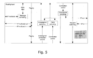
- Fig. 5 illustrates a possible implementation of the routing layer.
- the routing layer has mainly the task of sending connection and session control messages between upper and lower layer software components even when these components are residing in physical separate base stations.
- Establishment of incoming communication sessions is done indirectly by paging the wireless terminal on one of more base stations.
- Paging messages are sent downwards from upper layer to the local lower layer and sent via IP multicast to other base stations.
- IP multicast paging messages the routing layer is sending these downwards to the lower layer and a paging message is broadcasted on the radio transceiver.
- paging messages can be broadcasted on multiple base stations.
- Physical connections between a wireless terminal and the base station are established by the wireless terminal.
- a connection is created using a randomly chosen unassigned PMID (Portable MAC identifier).
- the routing layer "Unassigned switching" will route connection control messages for connections using unassigned PMID to the upper layer in any base station having available resources.
- an upper layer session is created in a basestation and a unique PMID is assigned for addressing the communication with the wireless terminal.
- the PMID is constructed such that a unique basestation identity is included in the PMID.
- connection control messages will include the PMID, and this will allow the "PMID switch” by lookup in a table to send the connection control messages via IP network to basestation in which the upper layer session exists.
- the "Downwards switch” performs lookup in a table containing the mapping between PMID and IP address and forwards connection control messages to the proper lower layer independent of where it physically is located.
- the "Inbound switching" determines whether an incoming message is designated for upper or lower layers.
- the invention provides a wireless base station device for handling wireless communication, e.g. DECT, between a plurality of associated wireless terminals and an IP network.
- the base station device has a radio transceiver, a network interface, and a processor with communication application and a communication session management software.
- the communication session management is arranged to control a communication session with an associated wireless terminal (upper layer management), while wireless communication with said associated wireless terminal involved with said communication session (lower layer) is handled by another base station device.
- the base station can manage separate operation of its upper and lower layers, thereby enabling e.g. hand-over of a session to and from other base stations. This allows self contained single casing base station devices to operate in a network without the need for at central server, and still such network is easy to extend by adding base stations.
Landscapes
- Engineering & Computer Science (AREA)
- Computer Networks & Wireless Communication (AREA)
- Signal Processing (AREA)
- Multimedia (AREA)
- Business, Economics & Management (AREA)
- General Business, Economics & Management (AREA)
- Mobile Radio Communication Systems (AREA)
Abstract
Description
- The invention relates to the field of wireless Radio Frequency communication, such as Digital Enhanced Cordless Telecommunication (DECT) communication devices and networks. More specifically, the invention provides a wireless base station device which can e.g. form part of a wireless VoIP network without requiring a central server, thus providing a VoIP network which is scalable, i.e. which can be extended by further base stations, without requiring the user to reconfigure the system or its components.
- DECT or DECT/Cat-iq (Cordless Advanced Technology - internet and quality) protocols and devices are known to provide efficient and reliable communication of a speech data, e.g. by means of Voice over Internet Protocol (VoIP) communication, between a wireless handset and a base station.
- In small systems, a self-contained base station has a limited number of wireless handsets registered thereto. Such systems are rather economic and simple to install, but it is impossible to enhanced wireless coverage and increase the number of handsets outside the limit of the base station, unless repeater devices are used.
- In traditional larger setups for VoIP, a number of spatially distributed base stations communicate with a central server with software that manages to centrally control calls to/from a plurality of mobile wireless handsets. Hand-over or roaming between base stations, i.e. when a handset moves out of reach of one base station and into the coverage range of another base station, is also handled by the central the server. Such systems offer scalability, since it is often possible for the central server to manage addition of extra base stations.
- However, such central server setups suffer from several drawbacks. For small companies with a limited number of wireless handsets and a limited space covered by few base stations, a rather expensive and maintenance requiring central server is still needed for such system to function. Furthermore, in case an extension of such system is desired, the server configuration must be updated to handle one or more additional base stations. This may be rather complicated and thus requires a specialist, and therefore normal users are unable to perform such extension themselves. A dedicated server is a relative large overhead for small system confgurations.
- Thus, following the above description, it is an object of the present invention to provide a device and a system which is capable of providing a scalable DECT compatible VoIP network still with possibility of seamless hand-over of communication sessions, e.g. calls, between base stations. Preferably, the system is prepared to be self-configuring.
- According to a first aspect, the invention provides a wireless base station device arranged to handle wireless communication between a plurality of associated wireless terminals and an IP network, the device comprising
- a radio transceiver arranged to wirelessly communicate with the plurality of wireless terminals, and
- a network interface arranged to communicate with the IP network,
- a processor with software arranged to implement
- a communication application, and
- a communication session management for controlling sessions of communication with the plurality of associated wireless terminals,
- Given an IP network connection, a number of such base station devices spatially distributed will allow to form e.g. a DECT network, where wireless terminals in the form of mobile handsets can perform e.g. VoIP communication via the base station devices without the need for a central server to handle the each individual communication sessions. Since one single base station device includes communication session management, IP network interface, and wireless radio transceiver, several such base station devices can work together and ensure free roaming and seamless hand-over of on-going communication sessions (calls) because the communication session management is arranged to manage communication sessions where the wireless terminal communication is performed by the base station's own radio transceiver, or via another base station's radio transceiver in the network. This allows free roaming and hand-over of on-going communication sessions if a wireless terminal moves out of coverage of one base station and into the coverage of another base station. The session management can remain in the base station which initiated the session, while the physical wireless communication with the wireless terminal is handed over to another base station in the network.
- In other words, the functions of the radio transceiver and the processor in the base station are arranged such that they can function separately. The function of the traditional central server can be seen as distributed between the base station devices. This means that with such base station devices it is possible to increase system capacity and ability to handle a larger number of wireless terminals and to expand the wireless coverage by simply connecting further base station devices without the need to change software setting in a central server. This is advantageous for e.g. small companies that are growing in size: the wireless, e.g. DECT, network coverage can be easily scaled with the growth of the company withtout the initial large investment in a complicated and expensive server system which is normally required to implement such system scalability.
- The possibility of providing the base station with control software that ensures the base station to be highly self-configurable in the network, it is easy for a user to add a base station and thus extend the network without complicated updating and software configuration procedures.
- In the following various embodiments of the invention will be described.
- In preferred embodiments, the base station device is implemented with the radio transceiver, the network interface and the processor housed within one single casing. E.g. the device can be powered from the IP network connection, in case the network interface is a wired interface. Otherwise the device may be battery powered or powered from an external or internal power supply power from an external power net. It is to be understood that the various elements of the base station device may alternatively be implemented in two or more casings with wired interconnections.
- The device may be further arranged to handle wireless radio frequency communication with an associated wireless terminal involved with a communication session, while said communication session is controlled by an associated external device, such as an external wireless base station device. Thus, the base station can both handle management communication sessions which is executed by another base station, and the base station can also execute wireless communication in sessions managed by another base station. This allows the base station to form part of flexible networks where seamless hand-over can be performed both to and from the base station device.
- The device may be seen as divided into "lower layer" functionalities, i.e. radio communication with the wireless terminals, and "upper layer" functionalieis, i.e. session management. In a preferred embodiment, the lower layer comprises the radio transceiver, and the upper layer comprises the communication application and the communication session management, wherein the device comprises a routing layer serving to separate the lower layer and the upper layer so as to allow the upper layer to handle communication sessions with associated lower layers physically separate from the upper layer. Thus, such routing layer serves to implement the separtion of upper layer and lower layer functions in the base station device. The routing layer can be implemented in various ways, but preferably the routing layer includes logics enabling handling of addressing of messages between the upper and lower layers and the network interface, so as to allow the upper and lower layers to function separately together with upper and lower layers physically present in an external base station device connected to the IP network. Preferably, the lower layer comprises processing means for coding of user data, such as transcoding of audio data. Audio transcoding capabilities will allow the lower layer to translate user data in the form of audio data from a mobile handsets to various audio standards to the IP network.
- Preferably, the communication session management is arranged to hand-over an on-going communication session with an associated wireless terminal to an associated external wireless base station device. Preferably, such hand-over is performed by the device being arranged to receive user data from said external wireless base station device and to relay the user data to the IP network by maintaining an IP address already assigned to the communication session before hand-over. Thus, the external base station to which the session has been handed-over now performs the wireless terminal communication, while the base station receives and relays the user data, e.g. audio data, to the IP network and still performs management of the session (if the session was initiated by the device).
- In a wireless network systems, such as DECT, communication sessions can be initiated either from network side or wireless terminal side. However, the physical wireless connections are normally only established by the wireless terminal towards suitable basestations. In order to support communication sessions to be initiated from network side, the wireless terminals performs a initial or regular locations registration procedure, that initiates upper layer instance in a basestation. When communications sessions, such as incoming calls, have to be initiated from network side, paging messages are broadcasted on one or more basestations in order trig the wireless terminals to establish suitable physical wireless connections to serve the network upper layer communication sessions.
- In one embodiment, the device is arranged to receive paging information from the IP network, and to transmit paging information in a wireless signal via the radio transceiver, so as to allow roaming of the plurality of associated wireless terminals. Thus, by such distribution among base station devices of paging, a wireless terminal can receive e.g. a VoIP call irrespective of which base station device of the network the terminals can wirelessly reach.
- In one embodiment, the processor is arranged to exchange system configuration data and identity information on the plurality of associated wireless terminals via the IP network, such as according to a prestored scheme or upon request. Thus, with the device being arranged to distribute such information, all base stations of the network can be updated of system and wireless terminal information. This allows e.g. a network user or manager to update system configuration on only one base station of the network. This base station then serves to update the other base stations in the network.
- In one embodiment, the plurality of associated wireless terminals comprises a plurality of wireless mobile handsets arranged for speech communication, such as wireless mobile handsets arranged for DECT communication. The radio transceiver is then arranged for DECT communication, and the device further comprises audio processing means arranged for processing of DECT audio data. As already mentioned, such embodiments are suited as base stations in a cordless phone network which is easy to expand by further base stations. Especially, the device may include audio processing arranged to handle wide-band audio data.
- Preferably, the device is arranged for timing synchronization of the radio transceiver with an associated external wireless base station device.
- The device may be arranged for assignment of an identification number on the IP network. This allows several base stations to identify themselves to each other as belonging to a specific wireless network and thus to be able to cooperate and distribute upper layer and lower layer functionalities as already described.
- In general, the device may be arranged to wirelessly communicate according to a communication standard being one of: DECT/CAT-iq, Bluetooth, WiFi, GSM, LTE, Wimax, 3G, and 4G. The communication application may comprise a VoIP application so as to enable the device to handle VoIP communication between wireless terminals and the IP network.
- The network interface may be a wired or wireless IP network interface, e.g. an interface arranged for a wired Ethernet connection or a wired VDSL connection. Especially, the device may be arranged to receive power to run at least some of or all of the circuits of the base station device via the Ethernet connection.
- The device may be implemented by one single processor, i.e. the processor being arranged to carry out all processing required by the upper layer, routing layer and lower layers. However, in some versions it may be desired to separate different functionalities of the device between two or more processors.
- The base station may include algorithms arranged to distribute communication session management to non-busy base stations in the network, e.g. by the base station device being arranged to transmit, via the IP network, information regarding the number communication sessions currently handled by the base station device. This will allow the base stations to automatically distribute session management to more or less idle base station devices of the network and thus utilize processing capacity in such devices, thereby enhancing the total capacity in a network of base station devices.
- In a second aspect, the invention provides a wireless network system comprising
- a plurality of wireless base station devices according to the first aspect, and
- a plurality of wireless terminals arranged for wireless communication via the radio transceiver of at least one of the plurality of wireless base station devices.
- It is appreciated that embodiments mentioned for one aspect may in any way be combined with embodiments of any one or more embodiments of the other aspects.
- In the following, the invention will be described in more details by referring to embodiments illustrated in the accompanying drawings, of which
-
Fig. 1 illustrates a wireless base station device embodiment suited for VoIP communication with mobile terminals, -
Fig. 2 illustrates a block diagram of a base station device embodiment with elements of upper layers and lower layers indicated, and with indication of an intermediate routing layer, -
Figs. 3a, 3b, and 3c illustrate different communication session scenario so as to illustrate the role of the separate upper and lower layers of the base station device, -
Fig. 4 illustrates an example of a VoIP network with three base stations each with one or two mobile handsets within their respective radio ranges, and -
Fig. 5 illustrates a block diagram of an example of elements contained in a routing layer. -
Fig. 1 illustrates basic elements of a base station device embodiment connected via a network interface NI to an IP network, e.g. a wired Ethernet, and capable of wireless communication with three wireless terminals T1, T2, and T3, e.g. mobile handsets, according to a DECT/CAT-iq protocol. - A processor serves to run a communication application, here illustrated as a VoIP application, and software implementing communication session management functionalities CSM allowing the base station device to handle and control a communication session with one or more of the wireles terminals T1, T2, T3 by means of the wireless radio transceiver RT. These functions performed by the processor can be seen as basic parts of what can be denoted "upper layer" UL functionalities. The radio transceiver RT, here illustrated as a DECT/CAT-iq compatible radio transceiver RT, can be denoted "lower layer" LL since it serves to perform the physical wireless communication with the wireless terminals T1, T2, T3. The special feature of the base station device according to the illustrated embodiment is that it includes a "routing layer" RL, which serves to handle communication between the upper layer UL, the lower layer LL, and the network interface NI. This allows separate operation of the upper layer UL and the lower layer LL. Hereby, several similar base station devices can be connected to the IP network and distribute upper layer and lower layer handling of one communication session between two base station devices. Preferably, each base station devices can handle:
- 1) both lower layer and upper layer handling of a communication session,
- 2) only lower layer communication in a communication session where another base station device handles upper layer functions of the session, and
- 3) upper layer communication in a communication session where another base station device handles lower layer communication.
- This allows a network to support free roaming and seamless hand-over. In all cases 1)-3), the routing layer RL severes to communicate between the upper layer and the lower layer - whether these are physically present within one single device, or whether only the upper layer UL or the lower layer LL in the device is active in the communication session. If for one communication session the upper and lower layer functionalities are in different devices, the routing layer RL will perform the necessary intercommunication via the network interface NI and thus the IP network to its routing layer counter part in the external base station device.
- In
Fig. 1 the base station device is illustrated as contained within one single casing, e.g. with all its circuit elements power from the wired Ethernet connection. Thus, the device may be in the form of one single casing with with only one or more IP network connection sockets available from outside. The radio transceiver may include an internal antenna, or it may be connected to an antenna socket available from outside. The processor may be arranged to perform all required processing in both upper layer UL, routing layer RL, and lower layer LL. In simple low cost versions, one single processor can handle all processing required to implement UL, RL, and LL functions. - In the following, a number of abbreviations are used:
- DECT
- Digital Enhanced Cordless Telecommunication
- DLC
- Data Link Control
- DSP
- Digital Signal Processor
- Eth
- Ethernet
- IP
- Internet Protocol
- IWU
- Inter Working Unit
- MAC
- Media Access Control
- NWK if
- Network Interface
- NWK
- Network
- PMID
- Portable MAC identifier
- PARI
- Primary Access Rights Identifier
- PBX
- Private Branch eXchange
- RFP
- Radio Fixed Part
- RFPI
- Radio Fixed Part Identifier
- RPN
- Radio Part Number
- RSSI
- Received Signal Strength Indication
- RTP
- Real Time Protocol
- SIP
- Session Initiated Protocol
- STUN
- Session Traversal Utilities for NAT
- UA
- User Agent
- VoIP
- Voice over IP
- WRS
- Wireless Relay Station
-
Fig. 2 illustrates in more details the functions included in the upper layer UL and in the lower layer LL of one base station device embodiment. The upper layer UL includes a communication application, here a VoIP application, and communication management and call control facilities, as already described in relation toFig. 1 . It is noted that the lower layer includes all audio processing, i.e. audio driver, DSP control and MAC, thus allowing coding of user data from the wireless terminals in the form of audio data. If necessary, the base station device includes processing means to transcode the audio data. - Information in the information database is exchanged and synchronized via the routing layer. Data are formatted and added header information and distributed via the IP network, e.g. using IP multicast. The distribution may be performed at regular time intervals, or upon any update. E.g. data in the database are supplied with a time stamp which will enable the base station to verify if update of some data in the information database need to be updated.
-
Figs. 3a-c illustrate the role of the upper, routing, and lower levels of a base station device in three different scenario, where up to three base station devices B1, B2, B3 are involved in one single communication session with a wireless terminal. -
Fig. 3a shows a simple situation where a base station device B1 has an upper layer which manages a communication session with the wireless terminal, and wherein the lower level of the same base station device B1 handles the physical wireless communication with the wireless terminal. Media data are routed from the lower layer via the routing layer to the IP network. Session control data are communicated with the wireless terminal via the lower layer, the routing layer, and the upper layer, and again via the routing layer to the IP network. -
Fig. 3b shows a situation where two base station devices B1, B2 are involved in a communication session with the wireless terminal. E.g. the session has been initiated as described in relation toFig. 3a , i.e. the session being initiated and solely handled by B1. The communication connection can then be handed over to B2, e.g. in case the wireless terminal has moved out of wireless reach of B1, whereas communication session management is still handled by B1. Thus, now the lower layer of B2 handles the wireless communication with the wireless terminal and routes both media data and session control data via its routing layer to the IP network and thus enables the routing layer of B1 to receive both via its routing layer. The media data are then routed to the lower layer of B1, while the session control data are routed to the upper layer which still controls the communication session, whereas the upper layer of B2 is not involved in the communication session. This free the upper layer of B2 for controlling other communication sessions which may be handled by its own lower layer or by a lower layer of an external base station, e.g. B1. -
Fig. 3c shows a situation where a communication session involves three base station devices B1, B2, B3. E.g. the situation occurs if a communication session is initiated by upper layer of B1 and lower layer of B2, e.g. because the latest location registration of the wireless terminal was performed on B1. The communication session may then have been handed over to B3, e.g. due to the wireless terminal having moved out of wireless reach of B2 but into the wireless coverage range of the radio transceiver of the lower level of B3. This situation would be similar to that illustrated inFig. 3b . However, e.g. due to B2 and B3 being involved in too many communication sessions, while B1 has free upper level capacity, B2 may broadcast a request to hand over upper layer handling of the communication session, or because the latest location registration of the terminal was performed on B1. Due B1 being the available base station on the network with the highest extra capacity, it is selected to receive upper layer control of the communication session. Thus, hereby all three base stations B1, B2, B3 are involved in the communication session. B1 handles upper layer functions, relayed via routing layers of B2 and B3. B3 handles lower layer communication with the wireless terminal and realys media data via routing layers of B3 and B3 to lower layer of B2 and further via B2 routing layer to the IP network. -
Fig. 4 illustrates an example network of three base station devices B1, B2, B3 according to the invention which are connected to an IP network, thus enabling VoIP communication with one of the four wireless terminals distributed within the wireless coverage (circles) of each of the base station devices B1, B2, B3. This allows VoIP calls between the wireless terminals and an IP phone or an IP phone switch, an IP PBX. - Preferably, the base station device are configured for automatic distribution of system configuration data via IP network so as to allow a user to update the system by updating data in one of the base stations B1, B2, B3 only. The same applies to expansion of the system which can be easily done by connecting an extra base station device which has been informed about the identify of the network which it is expected to be a part of. The base station will then automatically be updated with relevant network information that allows the base station to function in the network.
- If a base station device fails, the network of base stations is also flexible, since maybe only the radio transceiver of the base station fails, while still the routing and upper layer facilities can still be used in the network. Also the risk of loosing an on-going communication session is minimal due to the possibility that two or three base station devices may be involved in the lower layer handling of the communication session. Thus, even if the lower layer of one base station fails, another base station may be able to take over its tasks and keep the communication session running. If the upper layer of one base station fails, then the on-going communication session is lost, but upper layer activities, e.g. location registration, can be performed on another base station in the network.
-
Fig. 5 illustrates a possible implementation of the routing layer. As mentioned, the routing layer has mainly the task of sending connection and session control messages between upper and lower layer software components even when these components are residing in physical separate base stations. - Establishment of incoming communication sessions, such as phone calls, is done indirectly by paging the wireless terminal on one of more base stations. Paging messages are sent downwards from upper layer to the local lower layer and sent via IP multicast to other base stations. When receiving IP multicast paging messages the routing layer is sending these downwards to the lower layer and a paging message is broadcasted on the radio transceiver. Hence, paging messages can be broadcasted on multiple base stations.
- Physical connections between a wireless terminal and the base station are established by the wireless terminal. When no upper layer session exists for a wireless terminal, a connection is created using a randomly chosen unassigned PMID (Portable MAC identifier). The routing layer "Unassigned switching" will route connection control messages for connections using unassigned PMID to the upper layer in any base station having available resources. Subsequently, an upper layer session is created in a basestation and a unique PMID is assigned for addressing the communication with the wireless terminal. The PMID is constructed such that a unique basestation identity is included in the PMID. All following connection control messages will include the PMID, and this will allow the "PMID switch" by lookup in a table to send the connection control messages via IP network to basestation in which the upper layer session exists. The "Downwards switch" performs lookup in a table containing the mapping between PMID and IP address and forwards connection control messages to the proper lower layer independent of where it physically is located.
- The "Inbound switching" determines whether an incoming message is designated for upper or lower layers.
- To sum up, the invention provides a wireless base station device for handling wireless communication, e.g. DECT, between a plurality of associated wireless terminals and an IP network. The base station device has a radio transceiver, a network interface, and a processor with communication application and a communication session management software. The communication session management is arranged to control a communication session with an associated wireless terminal (upper layer management), while wireless communication with said associated wireless terminal involved with said communication session (lower layer) is handled by another base station device. Thus, the base station can manage separate operation of its upper and lower layers, thereby enabling e.g. hand-over of a session to and from other base stations. This allows self contained single casing base station devices to operate in a network without the need for at central server, and still such network is easy to extend by adding base stations.
- Although the present invention has been described in connection with the specified embodiments, it is not intended to be limited to the specific form set forth herein. Rather, the scope of the present invention is limited only by the accompanying claims. In the claims, the term "comprising" or "including" does not exclude the presence of other elements. Additionally, although individual features may be included in different claims, these may possibly be advantageously combined, and the inclusion in different claims does not imply that a combination of features is not feasible and/or advantageous. In addition, singular references do not exclude a plurality. Thus, references to "a", "an", "first", "second" etc. do not preclude a plurality. Furthermore, reference signs in the claims shall not be construed as limiting the scope.
Claims (15)
- Wireless base station device arranged to handle wireless communication between a plurality of associated wireless terminals and an IP network, the device comprising- a radio transceiver arranged to wirelessly communicate with the plurality of wireless terminals,- a network interface arranged to communicate with the IP network, and- a processor with software arranged to implementwherein the communication session management is arranged to control a communication session with an associated wireless terminal, while wireless radio frequency communication with said associated wireless terminal involved with said communication session is handled by an associated external device, such as an external wireless base station device.- a communication application, and- a communication session management for controlling sessions of communication with the plurality of associated wireless terminals,
- Device according to claim 1, wherein the wireless base station device is further arranged to handle wireless radio frequency communication with an associated wireless terminal involved with a communication session, while said communication session is controlled by an associated external device, such as an external wireless base station device.
- Device according to claim 1 or 2, wherein a lower layer comprises the radio transceiver, wherein an upper layer comprises the communication application and the communication session management, and wherein the device comprises a routing layer serving to separate the lower layer and the upper layer so as to allow the upper layer to handle communication sessions with associated lower layers physically separate from the upper layer.
- Device according to claim 3, wherein the lower layer further comprises processing means for coding of user data, such as transcoding of audio data.
- Device according to any of the preceding claims, wherein the radio transceiver, the network interface and the processor are housed within one single casing.
- Device according to any of the preceding claims, arranged to hand-over an on-going communication session with an associated wireless terminal to an associated external wireless base station device.
- Device according to claim 6, wherein the device is arranged to receive user data from said external wireless base station device and to relay the user data to the IP network by maintaining an IP address already assigned to the communication session before hand-over.
- Device according to any of the preceding claims, wherein the device is arranged to receive paging information from the IP network, and to transmit paging information in a wireless signal via the radio transceiver, so as to allow roaming of the plurality of associated wireless terminals.
- Device according to any of the preceding claims, wherein the processor is arranged to exchange system configuration data and identity information on the plurality of associated wireless terminals via the IP network, such as according to a prestored scheme or upon request.
- Device according to any of the preceding claims, wherein the plurality of associated wireless terminals comprises a plurality of wireless mobile handsets arranged for speech communication, such as wireless mobile handsets arranged for DECT communication.
- Device according to any of the preceding claims, wherein the wireless base station device is arranged for timing synchronization of the radio transceiver with an associated external wireless base station device.
- Device according to any of the preceding claims, wherein the wireless base station device is arranged for assignment of an identification number on the IP network.
- Device according to any of the preceding claims, wherein the wireless radio transceiver is arranged to wirelessly communicate according to a communication standard being one of: DECT/CAT-iq, Bluetooth, WiFi, GSM, LTE, Wimax, 3G, and 4G.
- Device according to any of the preceding claims, wherein the communication application comprises a VoIP application so as to enable the device to handle VoIP communication between wireless terminals and the IP network.
- Wireless network system comprising- a plurality of wireless base station devices according to any of claims 1-14, and- a plurality of wireless terminals arranged for wireless communication via the radio transceiver of at least one of the plurality of wireless base station devices.
Priority Applications (10)
| Application Number | Priority Date | Filing Date | Title |
|---|---|---|---|
| EP10197291.7A EP2472812B1 (en) | 2010-12-29 | 2010-12-29 | Scalable wireless multicell voip architecture |
| KR1020137019532A KR20140048839A (en) | 2010-12-29 | 2011-12-16 | Scalable wireless multicell voip architecture |
| AU2011351900A AU2011351900B2 (en) | 2010-12-29 | 2011-12-16 | Scalable wireless multicell VoIP architecture |
| CN201180063750.8A CN103348650B (en) | 2010-12-29 | 2011-12-16 | Extendible wireless multicell voip architecture |
| CA2858917A CA2858917C (en) | 2010-12-29 | 2011-12-16 | Scalable wireless multicell voip architecture |
| RU2013135401/08A RU2584487C2 (en) | 2010-12-29 | 2011-12-16 | Scalable wireless multicell voip architecture |
| US13/995,632 US9100928B2 (en) | 2010-12-29 | 2011-12-16 | Scalable wireless multicell VoIP architecture |
| PCT/DK2011/050488 WO2012089209A1 (en) | 2010-12-29 | 2011-12-16 | Scalable wireless multicell voip architecture |
| JP2013546590A JP2014506055A (en) | 2010-12-29 | 2011-12-16 | Scalable wireless multi-cell VoIP architecture |
| ZA2013/04603A ZA201304603B (en) | 2010-12-29 | 2013-06-21 | Scalable wireless multicell voip architecture |
Applications Claiming Priority (1)
| Application Number | Priority Date | Filing Date | Title |
|---|---|---|---|
| EP10197291.7A EP2472812B1 (en) | 2010-12-29 | 2010-12-29 | Scalable wireless multicell voip architecture |
Publications (2)
| Publication Number | Publication Date |
|---|---|
| EP2472812A1 true EP2472812A1 (en) | 2012-07-04 |
| EP2472812B1 EP2472812B1 (en) | 2014-02-12 |
Family
ID=44063691
Family Applications (1)
| Application Number | Title | Priority Date | Filing Date |
|---|---|---|---|
| EP10197291.7A Active EP2472812B1 (en) | 2010-12-29 | 2010-12-29 | Scalable wireless multicell voip architecture |
Country Status (9)
| Country | Link |
|---|---|
| US (1) | US9100928B2 (en) |
| EP (1) | EP2472812B1 (en) |
| JP (1) | JP2014506055A (en) |
| KR (1) | KR20140048839A (en) |
| CN (1) | CN103348650B (en) |
| CA (1) | CA2858917C (en) |
| RU (1) | RU2584487C2 (en) |
| WO (1) | WO2012089209A1 (en) |
| ZA (1) | ZA201304603B (en) |
Cited By (1)
| Publication number | Priority date | Publication date | Assignee | Title |
|---|---|---|---|---|
| CN111867008A (en) * | 2020-05-21 | 2020-10-30 | 厦门亿联网络技术股份有限公司 | Multi-mode base station and cordless communication system |
Citations (3)
| Publication number | Priority date | Publication date | Assignee | Title |
|---|---|---|---|---|
| EP1345462A1 (en) * | 2002-03-02 | 2003-09-17 | Ascom AG | Cordless telecommunication system and operating method therefor |
| US20070280252A1 (en) * | 2006-06-02 | 2007-12-06 | Inventec Multimedia & Telecom Corporation | System and method of realizing voice over internet protocol by means of digital enhanced cordless telecommunication |
| US20080026775A1 (en) * | 2000-04-07 | 2008-01-31 | Nitzan Arazi | Wireless Private Branch Exchange (WPBX) and Communicating Between Mobile Units and Base Stations |
Family Cites Families (16)
| Publication number | Priority date | Publication date | Assignee | Title |
|---|---|---|---|---|
| FI98176C (en) * | 1995-06-07 | 1997-04-25 | Nokia Mobile Phones Ltd | Implementation of mutual rate adaptations in data services between GSM and DECT system |
| US5940758A (en) * | 1996-06-28 | 1999-08-17 | Lucent Technologies Inc. | Wireless handset paging utilizing connection endpoint service identifiers |
| ES2292430T3 (en) * | 1999-02-24 | 2008-03-16 | Telefonaktiebolaget Lm Ericsson (Publ) | METHODS AND SYSTEMS TO DIRECT THE CALL AND NEGOTIATION CODE-DECODER IN VOICE / DATA / INTERNET / RADIO HYBRID SYSTEMS. |
| US7035932B1 (en) * | 2000-10-27 | 2006-04-25 | Eric Morgan Dowling | Federated multiprotocol communication |
| US20030125023A1 (en) * | 2001-03-15 | 2003-07-03 | Eyal Fishler | Method and system for providing a wireless terminal communication session integrated with data and voice services |
| US20030148779A1 (en) * | 2001-04-30 | 2003-08-07 | Winphoria Networks, Inc. | System and method of expediting call establishment in mobile communications |
| EP1257132A1 (en) * | 2001-05-08 | 2002-11-13 | Telefonaktiebolaget L M Ericsson (Publ) | Apparatus for integrating mobile telephones as terminals of a private communication system |
| US6879600B1 (en) * | 2002-06-03 | 2005-04-12 | Sprint Spectrum, L.P. | Method and system for intersystem wireless communication session arbitration |
| KR100800879B1 (en) * | 2004-03-05 | 2008-02-04 | 삼성전자주식회사 | Medium access control protocol structure in wireless communication system and data transmission method and hand-over method and system using the same |
| US7729700B2 (en) * | 2004-06-07 | 2010-06-01 | Nokia Corporation | Vertical network handovers |
| US20080085741A1 (en) * | 2006-10-10 | 2008-04-10 | Sony Ericsson Mobile Communications Ab | Method for providing an alert signal |
| US20080117076A1 (en) * | 2006-11-16 | 2008-05-22 | Arthur John Klaus | System and method for conducting bi-directional communication sessions with utility meters from a mobile device |
| JP4989450B2 (en) * | 2007-04-18 | 2012-08-01 | 京セラ株式会社 | Wireless communication system, base station, and wireless communication method |
| CN101355738B (en) * | 2007-07-25 | 2011-07-13 | 中兴通讯股份有限公司 | Voice transmission equipment and method of Abis interface discontinuousness transmission mode |
| KR101520346B1 (en) * | 2009-02-09 | 2015-05-14 | 노키아 솔루션스 앤드 네트웍스 오와이 | Link layer switching for local breakout |
| US20100329243A1 (en) * | 2009-06-29 | 2010-12-30 | Adrian Buckley | System And Method For Voice Service In An Evolved Packet System |
-
2010
- 2010-12-29 EP EP10197291.7A patent/EP2472812B1/en active Active
-
2011
- 2011-12-16 US US13/995,632 patent/US9100928B2/en active Active
- 2011-12-16 WO PCT/DK2011/050488 patent/WO2012089209A1/en active Application Filing
- 2011-12-16 JP JP2013546590A patent/JP2014506055A/en active Pending
- 2011-12-16 KR KR1020137019532A patent/KR20140048839A/en not_active Application Discontinuation
- 2011-12-16 RU RU2013135401/08A patent/RU2584487C2/en active
- 2011-12-16 CN CN201180063750.8A patent/CN103348650B/en active Active
- 2011-12-16 CA CA2858917A patent/CA2858917C/en active Active
-
2013
- 2013-06-21 ZA ZA2013/04603A patent/ZA201304603B/en unknown
Patent Citations (3)
| Publication number | Priority date | Publication date | Assignee | Title |
|---|---|---|---|---|
| US20080026775A1 (en) * | 2000-04-07 | 2008-01-31 | Nitzan Arazi | Wireless Private Branch Exchange (WPBX) and Communicating Between Mobile Units and Base Stations |
| EP1345462A1 (en) * | 2002-03-02 | 2003-09-17 | Ascom AG | Cordless telecommunication system and operating method therefor |
| US20070280252A1 (en) * | 2006-06-02 | 2007-12-06 | Inventec Multimedia & Telecom Corporation | System and method of realizing voice over internet protocol by means of digital enhanced cordless telecommunication |
Cited By (2)
| Publication number | Priority date | Publication date | Assignee | Title |
|---|---|---|---|---|
| CN111867008A (en) * | 2020-05-21 | 2020-10-30 | 厦门亿联网络技术股份有限公司 | Multi-mode base station and cordless communication system |
| EP3913936A1 (en) * | 2020-05-21 | 2021-11-24 | Yealink (Xiamen) Network Technology Co., Ltd. | Multimode base station and cordless communication system |
Also Published As
| Publication number | Publication date |
|---|---|
| KR20140048839A (en) | 2014-04-24 |
| EP2472812B1 (en) | 2014-02-12 |
| RU2584487C2 (en) | 2016-05-20 |
| JP2014506055A (en) | 2014-03-06 |
| CA2858917A1 (en) | 2013-07-05 |
| US20130272208A1 (en) | 2013-10-17 |
| AU2011351900A1 (en) | 2013-07-18 |
| ZA201304603B (en) | 2014-03-26 |
| CA2858917C (en) | 2019-02-12 |
| CN103348650A (en) | 2013-10-09 |
| CN103348650B (en) | 2015-08-26 |
| US9100928B2 (en) | 2015-08-04 |
| RU2013135401A (en) | 2015-02-10 |
| WO2012089209A1 (en) | 2012-07-05 |
Similar Documents
| Publication | Publication Date | Title |
|---|---|---|
| US10575173B2 (en) | Virtualization of the evolved packet core to create a local EPC | |
| CN101946542B (en) | Method and apparatus for inter-technology handoff of a multi-mode mobile station | |
| US7706796B2 (en) | User terminal-initiated hard handoff from a wireless local area network to a cellular network | |
| EP1762105B1 (en) | Routing calls to facilitate call handover | |
| KR101514955B1 (en) | Method for changing the wireless access point associated with a terminal in a wifi-dect wireless telecommunications network | |
| KR101057815B1 (en) | Tunneling-based mobility support device and method | |
| JPWO2006109462A1 (en) | Wireless communication system and wireless communication method | |
| MX2008014451A (en) | Method and apparatus for supporting an emergency call in a wireless metropolitan area network. | |
| JP2008533761A (en) | Communication method and communication system | |
| CN101203844A (en) | Method and apparatus to facilitate mobile station communications using internet protocol-based communications | |
| CN101142829B (en) | Method and apparatus for updating information within a communication system | |
| CA2858917C (en) | Scalable wireless multicell voip architecture | |
| AU2011351900B2 (en) | Scalable wireless multicell VoIP architecture | |
| JP2012507227A (en) | COMMUNICATION DEVICE AND SERVER, METHOD FOR THEM, AND COMPUTER PROGRAM | |
| KR100845229B1 (en) | Cug/vpn-based mobile voip service system in fmc(fixed-mobile convergence) enterprise networks | |
| KR100403732B1 (en) | Apparatus and method of registering subscriber location at public network in private wireless system | |
| WO2009106791A1 (en) | Mobile communication access point | |
| EP2104395A1 (en) | Mobile communication access point | |
| GB2413733A (en) | Voice over internet communications | |
| JP2005253024A (en) | Roaming system, roaming method, and mobile terminal | |
| JP2011250132A (en) | Wireless base station apparatus, wireless base station system, and method of establishing communication path for handover control | |
| JP2014197758A (en) | Ip telephone switching system | |
| KR20070047136A (en) | Wireless access point and call manager |
Legal Events
| Date | Code | Title | Description |
|---|---|---|---|
| AK | Designated contracting states |
Kind code of ref document: A1 Designated state(s): AL AT BE BG CH CY CZ DE DK EE ES FI FR GB GR HR HU IE IS IT LI LT LU LV MC MK MT NL NO PL PT RO RS SE SI SK SM TR |
|
| AX | Request for extension of the european patent |
Extension state: BA ME |
|
| PUAI | Public reference made under article 153(3) epc to a published international application that has entered the european phase |
Free format text: ORIGINAL CODE: 0009012 |
|
| RAP1 | Party data changed (applicant data changed or rights of an application transferred) |
Owner name: RTX A/S |
|
| 17P | Request for examination filed |
Effective date: 20121030 |
|
| 17Q | First examination report despatched |
Effective date: 20130315 |
|
| REG | Reference to a national code |
Ref country code: DE Ref legal event code: R079 Ref document number: 602010013485 Country of ref document: DE Free format text: PREVIOUS MAIN CLASS: H04L0029060000 Ipc: H04W0036000000 |
|
| GRAP | Despatch of communication of intention to grant a patent |
Free format text: ORIGINAL CODE: EPIDOSNIGR1 |
|
| RIC1 | Information provided on ipc code assigned before grant |
Ipc: H04W 36/00 20090101AFI20130902BHEP |
|
| INTG | Intention to grant announced |
Effective date: 20130919 |
|
| GRAS | Grant fee paid |
Free format text: ORIGINAL CODE: EPIDOSNIGR3 |
|
| GRAA | (expected) grant |
Free format text: ORIGINAL CODE: 0009210 |
|
| AK | Designated contracting states |
Kind code of ref document: B1 Designated state(s): AL AT BE BG CH CY CZ DE DK EE ES FI FR GB GR HR HU IE IS IT LI LT LU LV MC MK MT NL NO PL PT RO RS SE SI SK SM TR |
|
| REG | Reference to a national code |
Ref country code: GB Ref legal event code: FG4D |
|
| REG | Reference to a national code |
Ref country code: CH Ref legal event code: EP |
|
| REG | Reference to a national code |
Ref country code: AT Ref legal event code: REF Ref document number: 652593 Country of ref document: AT Kind code of ref document: T Effective date: 20140215 |
|
| REG | Reference to a national code |
Ref country code: IE Ref legal event code: FG4D |
|
| REG | Reference to a national code |
Ref country code: DE Ref legal event code: R096 Ref document number: 602010013485 Country of ref document: DE Effective date: 20140327 |
|
| REG | Reference to a national code |
Ref country code: NL Ref legal event code: T3 |
|
| REG | Reference to a national code |
Ref country code: SE Ref legal event code: TRGR |
|
| REG | Reference to a national code |
Ref country code: AT Ref legal event code: MK05 Ref document number: 652593 Country of ref document: AT Kind code of ref document: T Effective date: 20140212 |
|
| REG | Reference to a national code |
Ref country code: LT Ref legal event code: MG4D |
|
| PG25 | Lapsed in a contracting state [announced via postgrant information from national office to epo] |
Ref country code: NO Free format text: LAPSE BECAUSE OF FAILURE TO SUBMIT A TRANSLATION OF THE DESCRIPTION OR TO PAY THE FEE WITHIN THE PRESCRIBED TIME-LIMIT Effective date: 20140512 Ref country code: LT Free format text: LAPSE BECAUSE OF FAILURE TO SUBMIT A TRANSLATION OF THE DESCRIPTION OR TO PAY THE FEE WITHIN THE PRESCRIBED TIME-LIMIT Effective date: 20140212 Ref country code: IS Free format text: LAPSE BECAUSE OF FAILURE TO SUBMIT A TRANSLATION OF THE DESCRIPTION OR TO PAY THE FEE WITHIN THE PRESCRIBED TIME-LIMIT Effective date: 20140612 |
|
| PG25 | Lapsed in a contracting state [announced via postgrant information from national office to epo] |
Ref country code: PT Free format text: LAPSE BECAUSE OF FAILURE TO SUBMIT A TRANSLATION OF THE DESCRIPTION OR TO PAY THE FEE WITHIN THE PRESCRIBED TIME-LIMIT Effective date: 20140612 Ref country code: AT Free format text: LAPSE BECAUSE OF FAILURE TO SUBMIT A TRANSLATION OF THE DESCRIPTION OR TO PAY THE FEE WITHIN THE PRESCRIBED TIME-LIMIT Effective date: 20140212 Ref country code: CY Free format text: LAPSE BECAUSE OF FAILURE TO SUBMIT A TRANSLATION OF THE DESCRIPTION OR TO PAY THE FEE WITHIN THE PRESCRIBED TIME-LIMIT Effective date: 20140212 Ref country code: FI Free format text: LAPSE BECAUSE OF FAILURE TO SUBMIT A TRANSLATION OF THE DESCRIPTION OR TO PAY THE FEE WITHIN THE PRESCRIBED TIME-LIMIT Effective date: 20140212 Ref country code: ES Free format text: LAPSE BECAUSE OF FAILURE TO SUBMIT A TRANSLATION OF THE DESCRIPTION OR TO PAY THE FEE WITHIN THE PRESCRIBED TIME-LIMIT Effective date: 20140212 |
|
| PG25 | Lapsed in a contracting state [announced via postgrant information from national office to epo] |
Ref country code: RS Free format text: LAPSE BECAUSE OF FAILURE TO SUBMIT A TRANSLATION OF THE DESCRIPTION OR TO PAY THE FEE WITHIN THE PRESCRIBED TIME-LIMIT Effective date: 20140212 Ref country code: BE Free format text: LAPSE BECAUSE OF FAILURE TO SUBMIT A TRANSLATION OF THE DESCRIPTION OR TO PAY THE FEE WITHIN THE PRESCRIBED TIME-LIMIT Effective date: 20140212 Ref country code: LV Free format text: LAPSE BECAUSE OF FAILURE TO SUBMIT A TRANSLATION OF THE DESCRIPTION OR TO PAY THE FEE WITHIN THE PRESCRIBED TIME-LIMIT Effective date: 20140212 Ref country code: HR Free format text: LAPSE BECAUSE OF FAILURE TO SUBMIT A TRANSLATION OF THE DESCRIPTION OR TO PAY THE FEE WITHIN THE PRESCRIBED TIME-LIMIT Effective date: 20140212 |
|
| PG25 | Lapsed in a contracting state [announced via postgrant information from national office to epo] |
Ref country code: RO Free format text: LAPSE BECAUSE OF FAILURE TO SUBMIT A TRANSLATION OF THE DESCRIPTION OR TO PAY THE FEE WITHIN THE PRESCRIBED TIME-LIMIT Effective date: 20140212 Ref country code: CZ Free format text: LAPSE BECAUSE OF FAILURE TO SUBMIT A TRANSLATION OF THE DESCRIPTION OR TO PAY THE FEE WITHIN THE PRESCRIBED TIME-LIMIT Effective date: 20140212 Ref country code: DK Free format text: LAPSE BECAUSE OF FAILURE TO SUBMIT A TRANSLATION OF THE DESCRIPTION OR TO PAY THE FEE WITHIN THE PRESCRIBED TIME-LIMIT Effective date: 20140212 Ref country code: EE Free format text: LAPSE BECAUSE OF FAILURE TO SUBMIT A TRANSLATION OF THE DESCRIPTION OR TO PAY THE FEE WITHIN THE PRESCRIBED TIME-LIMIT Effective date: 20140212 |
|
| REG | Reference to a national code |
Ref country code: DE Ref legal event code: R097 Ref document number: 602010013485 Country of ref document: DE |
|
| PG25 | Lapsed in a contracting state [announced via postgrant information from national office to epo] |
Ref country code: PL Free format text: LAPSE BECAUSE OF FAILURE TO SUBMIT A TRANSLATION OF THE DESCRIPTION OR TO PAY THE FEE WITHIN THE PRESCRIBED TIME-LIMIT Effective date: 20140212 Ref country code: SK Free format text: LAPSE BECAUSE OF FAILURE TO SUBMIT A TRANSLATION OF THE DESCRIPTION OR TO PAY THE FEE WITHIN THE PRESCRIBED TIME-LIMIT Effective date: 20140212 |
|
| PLBE | No opposition filed within time limit |
Free format text: ORIGINAL CODE: 0009261 |
|
| STAA | Information on the status of an ep patent application or granted ep patent |
Free format text: STATUS: NO OPPOSITION FILED WITHIN TIME LIMIT |
|
| 26N | No opposition filed |
Effective date: 20141113 |
|
| REG | Reference to a national code |
Ref country code: DE Ref legal event code: R097 Ref document number: 602010013485 Country of ref document: DE Effective date: 20141113 |
|
| PG25 | Lapsed in a contracting state [announced via postgrant information from national office to epo] |
Ref country code: IT Free format text: LAPSE BECAUSE OF FAILURE TO SUBMIT A TRANSLATION OF THE DESCRIPTION OR TO PAY THE FEE WITHIN THE PRESCRIBED TIME-LIMIT Effective date: 20140212 |
|
| PG25 | Lapsed in a contracting state [announced via postgrant information from national office to epo] |
Ref country code: SI Free format text: LAPSE BECAUSE OF FAILURE TO SUBMIT A TRANSLATION OF THE DESCRIPTION OR TO PAY THE FEE WITHIN THE PRESCRIBED TIME-LIMIT Effective date: 20140212 |
|
| PG25 | Lapsed in a contracting state [announced via postgrant information from national office to epo] |
Ref country code: LU Free format text: LAPSE BECAUSE OF FAILURE TO SUBMIT A TRANSLATION OF THE DESCRIPTION OR TO PAY THE FEE WITHIN THE PRESCRIBED TIME-LIMIT Effective date: 20141229 |
|
| REG | Reference to a national code |
Ref country code: CH Ref legal event code: PL |
|
| REG | Reference to a national code |
Ref country code: IE Ref legal event code: MM4A |
|
| PG25 | Lapsed in a contracting state [announced via postgrant information from national office to epo] |
Ref country code: LI Free format text: LAPSE BECAUSE OF NON-PAYMENT OF DUE FEES Effective date: 20141231 Ref country code: IE Free format text: LAPSE BECAUSE OF NON-PAYMENT OF DUE FEES Effective date: 20141229 Ref country code: CH Free format text: LAPSE BECAUSE OF NON-PAYMENT OF DUE FEES Effective date: 20141231 |
|
| REG | Reference to a national code |
Ref country code: FR Ref legal event code: PLFP Year of fee payment: 6 |
|
| PG25 | Lapsed in a contracting state [announced via postgrant information from national office to epo] |
Ref country code: SM Free format text: LAPSE BECAUSE OF FAILURE TO SUBMIT A TRANSLATION OF THE DESCRIPTION OR TO PAY THE FEE WITHIN THE PRESCRIBED TIME-LIMIT Effective date: 20140212 |
|
| PG25 | Lapsed in a contracting state [announced via postgrant information from national office to epo] |
Ref country code: MC Free format text: LAPSE BECAUSE OF FAILURE TO SUBMIT A TRANSLATION OF THE DESCRIPTION OR TO PAY THE FEE WITHIN THE PRESCRIBED TIME-LIMIT Effective date: 20140212 |
|
| PG25 | Lapsed in a contracting state [announced via postgrant information from national office to epo] |
Ref country code: GR Free format text: LAPSE BECAUSE OF FAILURE TO SUBMIT A TRANSLATION OF THE DESCRIPTION OR TO PAY THE FEE WITHIN THE PRESCRIBED TIME-LIMIT Effective date: 20140513 Ref country code: BG Free format text: LAPSE BECAUSE OF FAILURE TO SUBMIT A TRANSLATION OF THE DESCRIPTION OR TO PAY THE FEE WITHIN THE PRESCRIBED TIME-LIMIT Effective date: 20140212 |
|
| PG25 | Lapsed in a contracting state [announced via postgrant information from national office to epo] |
Ref country code: TR Free format text: LAPSE BECAUSE OF FAILURE TO SUBMIT A TRANSLATION OF THE DESCRIPTION OR TO PAY THE FEE WITHIN THE PRESCRIBED TIME-LIMIT Effective date: 20140212 Ref country code: MT Free format text: LAPSE BECAUSE OF FAILURE TO SUBMIT A TRANSLATION OF THE DESCRIPTION OR TO PAY THE FEE WITHIN THE PRESCRIBED TIME-LIMIT Effective date: 20140212 Ref country code: HU Free format text: LAPSE BECAUSE OF FAILURE TO SUBMIT A TRANSLATION OF THE DESCRIPTION OR TO PAY THE FEE WITHIN THE PRESCRIBED TIME-LIMIT; INVALID AB INITIO Effective date: 20101229 |
|
| REG | Reference to a national code |
Ref country code: FR Ref legal event code: PLFP Year of fee payment: 7 |
|
| REG | Reference to a national code |
Ref country code: FR Ref legal event code: PLFP Year of fee payment: 8 |
|
| PG25 | Lapsed in a contracting state [announced via postgrant information from national office to epo] |
Ref country code: MK Free format text: LAPSE BECAUSE OF FAILURE TO SUBMIT A TRANSLATION OF THE DESCRIPTION OR TO PAY THE FEE WITHIN THE PRESCRIBED TIME-LIMIT Effective date: 20140212 |
|
| PG25 | Lapsed in a contracting state [announced via postgrant information from national office to epo] |
Ref country code: AL Free format text: LAPSE BECAUSE OF FAILURE TO SUBMIT A TRANSLATION OF THE DESCRIPTION OR TO PAY THE FEE WITHIN THE PRESCRIBED TIME-LIMIT Effective date: 20140212 |
|
| P01 | Opt-out of the competence of the unified patent court (upc) registered |
Effective date: 20230524 |
|
| PGFP | Annual fee paid to national office [announced via postgrant information from national office to epo] |
Ref country code: GB Payment date: 20231220 Year of fee payment: 14 |
|
| PGFP | Annual fee paid to national office [announced via postgrant information from national office to epo] |
Ref country code: SE Payment date: 20231220 Year of fee payment: 14 Ref country code: NL Payment date: 20231220 Year of fee payment: 14 Ref country code: FR Payment date: 20231221 Year of fee payment: 14 Ref country code: DE Payment date: 20231214 Year of fee payment: 14 |