EP2472806B1 - Techniques for improving channel estimation - Google Patents
Techniques for improving channel estimation Download PDFInfo
- Publication number
- EP2472806B1 EP2472806B1 EP11010291.0A EP11010291A EP2472806B1 EP 2472806 B1 EP2472806 B1 EP 2472806B1 EP 11010291 A EP11010291 A EP 11010291A EP 2472806 B1 EP2472806 B1 EP 2472806B1
- Authority
- EP
- European Patent Office
- Prior art keywords
- channel estimate
- subcarriers
- raw
- estimate values
- transmissions
- Prior art date
- Legal status (The legal status is an assumption and is not a legal conclusion. Google has not performed a legal analysis and makes no representation as to the accuracy of the status listed.)
- Not-in-force
Links
Images





Classifications
-
- H—ELECTRICITY
- H04—ELECTRIC COMMUNICATION TECHNIQUE
- H04L—TRANSMISSION OF DIGITAL INFORMATION, e.g. TELEGRAPHIC COMMUNICATION
- H04L25/00—Baseband systems
- H04L25/02—Details ; arrangements for supplying electrical power along data transmission lines
- H04L25/0202—Channel estimation
- H04L25/0224—Channel estimation using sounding signals
- H04L25/0228—Channel estimation using sounding signals with direct estimation from sounding signals
- H04L25/023—Channel estimation using sounding signals with direct estimation from sounding signals with extension to other symbols
- H04L25/0232—Channel estimation using sounding signals with direct estimation from sounding signals with extension to other symbols by interpolation between sounding signals
-
- H—ELECTRICITY
- H04—ELECTRIC COMMUNICATION TECHNIQUE
- H04L—TRANSMISSION OF DIGITAL INFORMATION, e.g. TELEGRAPHIC COMMUNICATION
- H04L25/00—Baseband systems
- H04L25/02—Details ; arrangements for supplying electrical power along data transmission lines
- H04L25/0202—Channel estimation
- H04L25/0212—Channel estimation of impulse response
-
- H—ELECTRICITY
- H04—ELECTRIC COMMUNICATION TECHNIQUE
- H04L—TRANSMISSION OF DIGITAL INFORMATION, e.g. TELEGRAPHIC COMMUNICATION
- H04L25/00—Baseband systems
- H04L25/02—Details ; arrangements for supplying electrical power along data transmission lines
- H04L25/0202—Channel estimation
- H04L25/022—Channel estimation of frequency response
-
- H—ELECTRICITY
- H04—ELECTRIC COMMUNICATION TECHNIQUE
- H04L—TRANSMISSION OF DIGITAL INFORMATION, e.g. TELEGRAPHIC COMMUNICATION
- H04L27/00—Modulated-carrier systems
- H04L27/26—Systems using multi-frequency codes
- H04L27/2601—Multicarrier modulation systems
- H04L27/2647—Arrangements specific to the receiver only
Definitions
- Document US 2007/110172 A1 relates to a method for performing channel estimation in an orthogonal frequency-division multiplexing system, the method including the steps of: receiving transmitting pilot symbols from a plurality of transmit antennas; forming a least-squares estimation matrix from the transmitted pilot symbols; forming a sparse smoothing matrix approximating a fixed weighting matrix, wherein each row vector in the sparse smoothing matrix contains one or more of the strongest weights in each row of the fixed weighting matrix; and deriving a channel estimation matrix from the sparse smoothing matrix and the least-squares estimation matrix.
- This document provide devices, systems and methods for communications, including OFDM and OFDMA communication devices, systems and methods that provide improved channel estimation as part of the process of decoding transmitted signals.
- a method of wireless communication is provided in independent claim 1 and further detailed in dependent claims 2-4.
- LTE OFDMA uplink it is often the case that the reference signal is configured to occupy several adjacent subcarriers. Because the channel response between adjacent subcarriers is typically highly correlated, the channel response from adjacent or nearby subcarriers can be combined and averaged so as to produce improved channel estimates. This technique is sometimes called channel estimate filtering in the frequency domain.
- LTE Long Term Evolution
- FIG. 1 illustrates an exemplary wireless communication system 100 that uses communication channels at different frequencies under OFDM or OFDMA to provide wireless communication services based in accordance with an embodiment.
- the system 100 may include a network of base stations (BSs) or base station transceivers (BSTs) 120 that are spatially distributed in a service area to form a radio access network for wireless subscribers or wireless subscriber stations (SSs) 110.
- BSs base stations
- BSTs base station transceivers
- SSs wireless subscriber stations
- a base station 120 may be designed to have directional antennas and to produce two or more directional beams to further divide each cell into different sections.
- Base station controllers (BSCs) 130 are connected, usually with wires or cables, to BSs 120 and control the connected BSs 120. Each BSC 130 is usually connected to and controls two or more designated BSs 120.
- the wireless system 100 may include a carrier packet network 140 that may be connected to one or more public switched telephone networks (PSTN) 150 and one or more packet data networks 160 (e.g., an IP network).
- PSTN public switched telephone networks
- a mobile switching center (MSC) 152 may be used as an interface between the BSCs 130 and the PSTN 150.
- MSC mobile switching center
- a packet data serving node 142 may be used to provide an interface between the carrier packet network 140 and the packet data network 160.
- a carrier packet network manager 144 may be connected to the carrier packet network 140 to provide various network management functions, such as such as an AAA server for authentication, authorization, and accounting (AAA) functions.
- AAA authentication, authorization, and accounting
- a base station (BSs) or base station transceiver (BSTs) 120 may include an OFDM receiver.
- OFDM receivers often require channel estimation as part of the process of decoding the signal that was transmitted.
- the transmitter is configured to periodically transmit a known reference signal (also known as a pilot signal) on certain subcarriers. By comparing the signal actually received to the signal known to have been transmitted, the receiver can estimate the response of the channel.
- a known reference signal also known as a pilot signal
- the reference signal is configured to occupy several adjacent subcarriers. Because the channel response between adjacent subcarriers is highly correlated, the channel response from adjacent or nearby subcarriers can be combined and averaged so as to produce improved channel estimates.
- the processor executable instructions may be stored in random access memory (RAM) within or in communication with the digital signal processor, or non-volatile memory within or in communication with the digital signal processor, such as a read-only memory (ROM), EEPROM (Electrically Erasable and Programmable Read Only Memory), or E-flash (embedded flash).
- RAM random access memory
- ROM read-only memory
- EEPROM Electrically Erasable and Programmable Read Only Memory
- E-flash embedded flash
- the executable instructions that configure the digital signal processor may implement a number of software modules or applications that communicate with one another and with hardware and software inside and outside of base station, in order to implement the functions of an OFDM receiver 200.
- the received baseband signal 202 is sent into a module 204 which removes the cyclic prefix (CP) from the OFDM symbol.
- the output of this module 204 is sent into the system DFT module 206 which transforms the signal from the time domain to the frequency domain.
- TOE time offset estimation
- D(i) (the i'th element of vector D) represent the e j 2 ⁇ i N DFT frequency component of the received time domain n signal.
- H raw represent the complex-valued vector coming out of the pilot compensation module.
- H raw i T 1 i + P 1 P i , 0 ⁇ i ⁇ N REF ⁇ 1.
- N REF is the number of subcarriers that are occupied by reference symbols.
- P 1 is the location of the first reference symbol in the output of the system DFT.
- P is a length N REF vector that contains the known reference symbols that were sent from the transmitter (it is assumed that no reference symbol has the value 0). For example, suppose it is known that the transmitter has transmitted 35 reference symbols (vector P) on subcarriers 123 through 157. In this case, P 1 would be 123 and N REF would be 35.
- the channel estimate filter (CEF) 212 module attempts to take advantage of the known a-priori auto-correlation properties of the channel response so as to produce refined channel estimates with improved accuracy.
- H actual represent the actual frequency domain channel response from the transmitter to the receiver, here seen as a complex-valued random column vector.
- H actual includes both the effects of the radio channel and of the receiver blocks up to the CEF block 212. Therefore, R H can be different for different TOE and TOC algorithms.
- x e H e ⁇ e + w e
- the ⁇ e column-vector is the parameter to be estimated
- H e is the observation matrix through which the parameter is observed
- w e is the noise column-vector that corrupts the estimates
- the x e column-vector contains the actual observations.
- the noise vector's autocovariance matrix ( Cw e ) is ⁇ n 2 I where ⁇ n 2 is the average power of the noise introduced by the receiver.
- H raw I H actual + N
- H filt will have the lowest mean squared error among all linear estimators.
- FIG. 3 is a diagram illustrating an exemplary OFDM receiver system in accordance with an embodiment.
- the received baseband signal 202 is sent into a module 204 which removes the cyclic prefix (CP) from the OFDM symbol.
- the output of this module 204 is sent into the system DFT 206 which transforms the signal from the time domain to the frequency domain.
- CP cyclic prefix
- the received baseband signal is also processed by the time offset estimation (TOE) module as indicated by the TOE module 212 in FIG. 3 .
- TOE time offset estimation
- TOE algorithms are available in the literature.
- One example TOE algorithm operates in the time domain and performs time domain correlations of the actual received signal against the time domain signal known to have been transmitted. The location of the peak of this time domain correlation is taken to be the time offset of the received signal.
- Time offset compensation (TOC) 208 is performed after the system DFT 206 based on the time offset estimated by the TOE module.
- the vector D of length N DFT represent the output of the system DFT where N DFT is the size of the system DFT.
- D(i) (the i'th element of vector D) represent the e j 2 ⁇ i N DFT frequency component of the received time domain signal. Note that i takes on values 0 through N DFT -1 inclusive.
- t d is, in general, a floating point number but is scaled such that if t d is 1, this indicates that the time offset was estimated as one sample, sampled at the sampling rate of the signal going into the system DFT.
- N REF is the number of subcarriers that are occupied by reference symbols.
- P 1 is the location of the first reference symbol in the output of the system DFT.
- P is a length N REF vector that contains the known reference symbols that were sent from the transmitter (it is assumed that no reference symbol is 0). For example, suppose it is known that the transmitter has transmitted 35 reference symbols (vector P) on subcarriers 123 through 157. In this case, P 1 would be 123 and N REF would be 35.
- H raw is a vector containing the raw channel estimates.
- H raw would perfectly represent the channel response between the transmitter and the receiver (H actual ).
- noise corrupts the channel estimates.
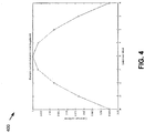
- FIG. 4 An example autocorrelation function r H raw for a typical radio channel is shown in FIG. 4 (graph 400) and FIG. 5 (graph 500).
- FIG. 4 demonstrates the magnitude of the correlation function and one can see that, for this particular channel, subcarriers adjacent to a particular subcarrier have a very high correlation coefficient (about 0.997).
- FIG. 5 demonstrates the angle of the same example autocorrelation function where one sees that in this particular case, the angle is nearly, but not completely linear. In general, it is not necessarily the case that the autocorrelation function is near-linear.
- This system 300 operates by taking advantage of the fact that the channel responses for adjacent subcarriers are highly correlated in many different types of propagation channels.
- the number of adjacent samples which can be considered 'highly correlated' will vary based on the statistical properties of the channel and the performance required from the receiver. For example, in critical implementations where receiver performance is paramount, it may not be reasonable to assume that adjacent carriers are highly correlated and hence one must implement a costly receiver that does not attempt to take advantage of high correlations among adjacent subcarriers. However, in some receiver designs, a tradeoff is possible where some performance loss can be accepted considering that the performance loss brings with it a significant savings in terms of implementation cost. The exact tradeoff between implementation cost and performance may be decided on a case by case basis.
- the number of subcarriers which are considered to be highly correlated is represented by the variable B. For example, if B is 3, then this embodiment assumes that the 3 subcarriers before a particular subcarrier, the subcarrier itself, and the 3 subcarriers after a particular subcarrier are highly correlated. In total, 2B+1 subcarriers are considered to be highly correlated. Although the actual value of B will vary from receiver to receiver and from channel to channel, in one embodiment, B is expected to typically be very small between 1 and 5.
- the system 300 introduces a second TOC module 302 in the receive chain which flattens the phase response of the autocorrelation function.
- the magnitude of the autocorrelation function of the signal coming out of the second TOC module will be the same as the magnitude of the autocorrelation function of the signal coming out of the PC module. The phase, however, will be affected.
- r H raw ′ t E H raw ′ n H raw ′ ⁇ n ⁇ t ⁇ s 2
- t R may be chosen such that the angle of the autocorrelation function of H raw ′ r H raw ′ will be near zero for subcarrier offsets between -B and +B. If the angle of r H raw was in fact a straight line, it would be possible to choose a t R value that would cause the angle of r H raw ′ to be precisely 0 for subcarrier offsets between -B and +B. However, in general, the angle of r H raw will seldom be a straight line and hence the angle of r H raw ′ will seldom be exactly equal to zero.
- t R N DFT 2 ⁇ ⁇ r H raw ⁇ B ⁇ ⁇ r H raw B 2 B where the ⁇ operator returns the angle of its argument as measured in radians.
- LMMSE linear minimum mean squared error estimator
- the noise vector's autocovariance matrix ( C w e ) is ⁇ n 2 Q Q H where ⁇ n 2 is the average power of the noise introduced by the receiver.
- H D Based on H D , the above equation optimally estimates H actual among all linear estimators. Instead of filtering H raw ′ directly which contains N ref samples, H D is filtered and it contains approximately N REF /B samples which is already approximately a factor of B reduction in implementation cost.
- H filt X Q ′ M smooth ′ Q H raw ′
- X is an interpolation matrix
- the parenthesis in the above equation serve to indicate how the implementation of the channel estimation filter 304 is expected to proceed so as to minimize the implementation cost.
- the Q matrix is applied to H raw ′ . This is a simple operation simply requiring several additions to be performed.
- Q H raw ′ will be a vector containing approximately N REF /B elements whereas H raw ′ contains N REF elements.
- M smooth ′ will be calculated based on the received signal power and the received noise power. This will produce a matrix with N REF rows and approximately N REF /B columns. Applying the Q ' matrix to this matrix will simply remove some rows of M smooth ′ and produce a final square matrix where each side is approximately of size (N REF /B)x(N REF /B).
- the Q ′ M smooth ′ matrix is then applied to the vector Q H raw ′ .
- the interpolation matrix X will then interpolate these estimates and produce the final estimates 306 for every subcarrier from 1 through N REF .
- interpolation matrix performs linear interpolation based on the nearest two available smoothed channel estimates.
- a graphical example 600 of the operation of the interpolation matrix is shown in FIG. 6 .
- the three solid vertical arrows (subcarriers 2, 4, and 6) in FIG. 6 represent the estimates produced by applying the Q ′ M smooth ′ matrix to the vector Q H raw ′ . These samples are used unmodified. The remaining samples are created by linear interpolation among the available subcarriers. For example, subcarrier 3 is created by averaging subcarriers 2 and 4.
- Subcarriers 0 and 1 are created by visualizing a line connecting the estimates for subcarrier 2 and 4 (indicated by a dashed line in FIG. 6 ) and calculating the value of that line for subcarriers 0 and 1.
- Subcarriers 5, 7, and 8 are similarly created based on a line connecting the channel estimates for subcarriers 4 and 6.
- the interpolation matrix X 2 ⁇ 1 0 1.5 ⁇ 0.5 0 1 0 0 .5 .5 0 0 1 0 0 .5 .5 0 0 1 0 ⁇ 0.5 1.5 0 ⁇ 1 2
- M simp c 0,0 c 0,1 c 0,2 c 0,3 c 0,4 0 0 0 0 0 0 0 c 1,0 c 1,1 c 1,2 c 1,3 c 1,4 0 0 0 0 0 0 0 c 2,0 c 2,1 c 2,2 c 2,3 c 2,4 0 0 0 0 0 0 0 c 3,0 c 3,1 c 3,2 c 3,3 c 3,4 0 0 0 0 0 0 0 0 c 4,0 c 4,1 c 4,2 c 4,3 c 4,4 0 0 0 0 0 0 0 0 c 4,0 c 4,1 c 4,2 c 4,3 c 4,4 0 0 0 0 0 0 0 0 c 4,0 c 4,1 c 4,2 c 4,3 c 4,4 0 0 0 0 0 0 0 0 c 4,0
- the leftmost L entries of the upper (L+1)/2 rows and the rightmost L entries of the lower (L+1)/2 rows will contain coefficients.
- the coefficient locations of any particular row will be located in the same positions as the non-zero entries of the previous row, but shifted to the right by one position.
- the leftmost L entries of the upper L/2 rows and the rightmost L entries of the lower L/2+1 rows will contain coefficients.
- the coefficient locations of any particular row will be located in the same positions as the non-zero entries of the previous row, but shifted to the right by one position.
- the optimal coefficients for M simp can be solved by calculating Q ′ M smooth ′ as if N ref was equal to L*(B+1)+B.
- This matrix is of size LxL and let d a,b represent the coefficient in row a, column b of M ref .
- the upper (L+1)/2 rows of M ref are assigned to the upper (L+1)/2 rows of M simp and the lower (L+1)/2 rows of M ref are assigned to the lower (L+1)/2 rows of M simp .
- the intermediate rows are all assigned the coefficients of row (L+1)/2-1 of M ref .
- the upper L/2 rows of M ref are assigned to the upper L/2 rows of M simp and the lower L/2 rows of M ref are assigned to the lower L/2 rows of M simp .
- the intermediate rows are all assigned the coefficients of row L/2-1 of M ref .
- the processing may also including interpolating the plurality of raw channel estimate values using an interpolation filter (e.g., averaging), as previously described.
- the processing may depend on the received signal power and received noise power, as previously discussed.
- the revised channel estimate may be obtained by processing 2*B+1 subcarrier results, where B is an integer.
- multiple raw channel estimates obtained on neighboring subcarriers are filtered to obtain a revised channel estimate, to help improve the receiver performance.
- the raw channel estimates may be filtered through a smoothing filter, which may be represented as a matrix multiplication operations, with the number of multiplications of the matrix being less than the length of the channel estimate.
- the disclosed and other embodiments and the functional operations described in this document can be implemented in digital electronic circuitry, or in computer software, firmware, or hardware, including the structures disclosed in this document and their structural equivalents, or in combinations of one or more of them.
- the disclosed and other embodiments can be implemented as one or more computer program products, i.e., one or more modules of computer program instructions encoded on a computer readable medium for execution by, or to control the operation of, data processing apparatus.
- the computer readable medium can be a machine-readable storage device, a machine-readable storage substrate, a memory device, a composition of matter effecting a machine-readable propagated signal, or a combination of one or more them.
- data processing apparatus encompasses all apparatus, devices, and machines for processing data, including by way of example a programmable processor, a computer, or multiple processors or computers.
- the apparatus can include, in addition to hardware, code that creates an execution environment for the computer program in question, e.g., code that constitutes processor firmware, a protocol stack, a database management system, an operating system, or a combination of one or more of them.
- a propagated signal is an artificially generated signal, e.g., a machine-generated electrical, optical, or electromagnetic signal, that is generated to encode information for transmission to suitable receiver apparatus.
- a computer program (also known as a program, software, software application, script, or code) can be written in any form of programming language, including compiled or interpreted languages, and it can be deployed in any form, including as a stand alone program or as a module, component, subroutine, or other unit suitable for use in a computing environment.
- a computer program does not necessarily correspond to a file in a file system.
- a program can be stored in a portion of a file that holds other programs or data (e.g., one or more scripts stored in a markup language document), in a single file dedicated to the program in question, or in multiple coordinated files (e.g., files that store one or more modules, sub programs, or portions of code).
- a computer program can be deployed to be executed on one computer or on multiple computers that are located at one site or distributed across multiple sites and interconnected by a communication network.
- the processes and logic flows described in this document can be performed by one or more programmable processors executing one or more computer programs to perform functions by operating on input data and generating output.
- the processes and logic flows can also be performed by, and apparatus can also be implemented as, special purpose logic circuitry, e.g., an FPGA (field programmable gate array) or an ASIC (application specific integrated circuit).
- Computer readable media suitable for storing computer program instructions and data include all forms of non volatile memory, media and memory devices, including by way of example semiconductor memory devices, e.g., EPROM, EEPROM, and flash memory devices; magnetic disks, e.g., internal hard disks or removable disks; magneto optical disks; and CD ROM and DVD-ROM disks.
- semiconductor memory devices e.g., EPROM, EEPROM, and flash memory devices
- magnetic disks e.g., internal hard disks or removable disks
- magneto optical disks e.g., CD ROM and DVD-ROM disks.
- the processor and the memory can be supplemented by, or incorporated in, special purpose logic circuitry.
Landscapes
- Engineering & Computer Science (AREA)
- Computer Networks & Wireless Communication (AREA)
- Signal Processing (AREA)
- Power Engineering (AREA)
- Mobile Radio Communication Systems (AREA)
- Noise Elimination (AREA)
Description
- This patent document relates to devices, systems and methods for communications based on orthogonal frequency division multiplexing (OFDM) or orthogonal frequency division multiple access (OFDMA).
- Wireless communication systems use electromagnetic waves to communicate with wireless communication devices located within cells of coverage areas of the systems. A radio spectral range or band designated or allocated for a wireless communication service or a particular class of wireless services may be divided into different radio carrier frequencies for generating different communication frequency channels. For a given wireless system, the communication capacity increases as the number of the communication frequency channels increases. Two different frequency channels, when placed too close to each other in frequency, can interfere or cross talk with each other to create noise and thus reduce the signal-to-noise ratio.
- One technique to reduce the minimum frequency spacing between two adjacent channels is to generate different channels within a given band by using the orthogonal frequency division multiplexing (OFDM) to generate channel spectral profiles that are orthogonal to one another without interference when different channels are centered at selected equally-spaced frequencies. Under the OFDM, the frequency spacing can be smaller than the minimum spacing in conventional frequency channels and hence increase the number of channels within a given band.
- The existing and developing specifications under IEEE 806.16x standards and Long Term Evolution (LTE) standards support wireless communications under OFDM and orthogonal frequency division multiple access (OFDMA). For example, the draft for IEEE 806.16d published in January 2004 provides technical specifications for OFDM and OFDMA wireless systems.
- Document
US 2008/137788 A1 relates to an apparatus and method of estimating a channel based on a channel delay spread in a mobile communication system. Pilot subcarriers are inserted between data subcarriers at predetermined intervals to estimate a channel at locations of the pilot subcarriers. An approximate channel delay spread value is estimated by using an autocorrelation value of a pilot signal. Then, a channel for data subcarriers between the pilot subcarriers is estimated by using a Wiener finite impulse response (FIR) filter that has a separate coefficient according to the estimated delay spread value. Accordingly, by changing the Wiener FIR filter coefficient according to the delay spread value of the channel, it is possible to estimate the channel so as to be adaptive for a change of the channel over time. Since the filter coefficients, which are calculated in advance, are used, it is possible to reduce the amount of calculation required when calculating the filter coefficients. As a result, an apparatus for estimating a channel can be easily achieved. - Document
US 2007/110172 A1 relates to a method for performing channel estimation in an orthogonal frequency-division multiplexing system, the method including the steps of: receiving transmitting pilot symbols from a plurality of transmit antennas; forming a least-squares estimation matrix from the transmitted pilot symbols; forming a sparse smoothing matrix approximating a fixed weighting matrix, wherein each row vector in the sparse smoothing matrix contains one or more of the strongest weights in each row of the fixed weighting matrix; and deriving a channel estimation matrix from the sparse smoothing matrix and the least-squares estimation matrix. - Document "A Novel Channel Estimation and Tracking Method for Wireless OFDM Systems Based on Pilots and Kalman Filtering" by Yuanjin relates to an on-line channel estimation and tracking method for wireless OFDM systems based on comb-type pilots. The simulation results are based on 802.11a wireless LAN standard.
- This document provide devices, systems and methods for communications, including OFDM and OFDMA communication devices, systems and methods that provide improved channel estimation as part of the process of decoding transmitted signals.
- The invention is set forth in the independent claims.
- In one aspect, a method of wireless communication is provided in
independent claim 1 and further detailed in dependent claims 2-4. - In another aspect, a system for wireless communication is provided in
independent claim 5 and further detailed in dependent claims 6-8. - In another aspect, a computer program product provided in independent claim 9 and further detailed in dependent claims 10-11.
- The present invention is defined and limited only by the scope of the appended claims. In the following, any embodiment(s) referred to and not falling within the scope of said appended claims is (are) to be interpreted as example(s) useful for understanding the present invention.
- These, and other aspects, are described in greater detail below.
- The components in the figures are not necessarily to scale, emphasis instead being placed upon illustrating various aspects thereof. Moreover, in the figures, like referenced numerals designate corresponding parts throughout the different views.
-
FIG. 1 shows an example of a wireless communication system that may implement an OFDM receiver system in accordance with an embodiment. -
FIG. 2 is a diagram illustrating an exemplary OFDM receiver system. -
FIG. 3 is a diagram illustrating an exemplary OFDM receiver system in accordance with an embodiment. -
FIG. 4 is a graph illustrating exemplary autocorrelation function for a radio channel. -
FIG. 5 is a graph illustrating exemplary autocorrelation function for a radio channel. -
FIG. 6 is a graph illustrating exemplary linear interpolation function implemented by an interpolation matrix multiplication operation. -
FIG. 7 is a block diagram representation of an example wireless network. -
FIG. 8 is a block diagram representation of a radio station. -
FIG. 9 is a flow chart representation of a process of wireless communications. -
FIG. 10 is a block diagram representation of a portion of a wireless communications device. - In one aspect, the disclosed techniques can be used to improve performance of an OFDM receiver. In another aspect, the disclosed techniques maintain the performance and the operation of an OFDM receiver under varying channel noise and signal to noise ratio (SNR) conditions.
- OFDM receivers often require channel estimation as part of the process of decoding the signal that was received. To assist the receiver in estimating channel response, often, the transmitter is configured to periodically transmit a known reference signal (sometimes called a pilot signal) on certain subcarriers. By comparing the signal actually received to the signal known to have been transmitted, the receiver can estimate the channel response.
- Furthermore, as in a Long Term Evolution (LTE) OFDMA uplink, it is often the case that the reference signal is configured to occupy several adjacent subcarriers. Because the channel response between adjacent subcarriers is typically highly correlated, the channel response from adjacent or nearby subcarriers can be combined and averaged so as to produce improved channel estimates. This technique is sometimes called channel estimate filtering in the frequency domain.
- Filtering may be a computationally intensive operation. In some cases, the number of multiplication operations may be reduced by taking advantage of the correlation of adjacent subcarriers of the channel for which estimates are being calculated. As further described below, highly correlated adjacent subcarriers may be identified, and the raw channel estimates in the frequency domain may be compensated by a time offset corresponding to a minimal angle of the autocorrelation function of the channel subcarrier and adjacent subcarriers. The resulting compensated raw channel estimate may be filtered by a filter with a length that corresponds to the number of highly correlated adjacent subcarriers, thus reducing the number of multiplication operations required to produce filtered channel estimates.
-
FIG. 1 illustrates an exemplarywireless communication system 100 that uses communication channels at different frequencies under OFDM or OFDMA to provide wireless communication services based in accordance with an embodiment. Thesystem 100 may include a network of base stations (BSs) or base station transceivers (BSTs) 120 that are spatially distributed in a service area to form a radio access network for wireless subscribers or wireless subscriber stations (SSs) 110. In some implementations, abase station 120 may be designed to have directional antennas and to produce two or more directional beams to further divide each cell into different sections. Base station controllers (BSCs) 130 are connected, usually with wires or cables, toBSs 120 and control the connectedBSs 120. EachBSC 130 is usually connected to and controls two or more designatedBSs 120. - The
wireless system 100 may include acarrier packet network 140 that may be connected to one or more public switched telephone networks (PSTN) 150 and one or more packet data networks 160 (e.g., an IP network). A mobile switching center (MSC) 152 may be used as an interface between theBSCs 130 and thePSTN 150. A packetdata serving node 142 may be used to provide an interface between thecarrier packet network 140 and thepacket data network 160. In addition, a carrierpacket network manager 144 may be connected to thecarrier packet network 140 to provide various network management functions, such as such as an AAA server for authentication, authorization, and accounting (AAA) functions. - Each
subscriber station 110 may be a stationary or mobile wireless communication device. Examples of a stationary wireless device may include desktop computers and computer servers. Examples of a mobile wireless device may include mobile wireless phones, Personal Digital Assistants (PDAs), and mobile computers. Asubscriber station 110 may be any communication device capable of wirelessly communicating withbase stations 120. - In one embodiment, the system in
FIG. 1 may be applied to the communication bands from 2 to 11 GHz under OFDM and OFDMA provided in IEEE 802.16x standards such as IEEE 802.16d (January, 2004). In OFDM and OFDMA systems, the available frequency band is divided into subcarriers at different frequencies that are orthogonal. In an OFDMA system, a subchannel is formed from a subset of subcarriers. In OFDMA, a total of 32 sub channels are allocated to each radio cell. - A base station (BSs) or base station transceiver (BSTs) 120 may include an OFDM receiver. OFDM receivers often require channel estimation as part of the process of decoding the signal that was transmitted. To assist the receiver in calculating the response of the channel, often, the transmitter is configured to periodically transmit a known reference signal (also known as a pilot signal) on certain subcarriers. By comparing the signal actually received to the signal known to have been transmitted, the receiver can estimate the response of the channel.
- Furthermore, as in an LTE OFDMA uplink, it is often the case that the reference signal is configured to occupy several adjacent subcarriers. Because the channel response between adjacent subcarriers is highly correlated, the channel response from adjacent or nearby subcarriers can be combined and averaged so as to produce improved channel estimates.
-
FIG. 2 shows a schematic diagram of an OFDM receiver which performs channel estimate filtering in the frequency domain. The exemplary processing shown insystem 200 to generate filtered channel estimates may be performed using any combination of hardware and software suitable to implement the required functionality disclosed herein. In one embodiment, the hardware may include a digital signal processor, such as a TMS320TCI6616 wireless base station system-on-a-chip from Texas Instruments Incorporated of Dallas, Texas. The digital signal processor may be configured with processor executable instructions. The processor executable instructions may be stored in random access memory (RAM) within or in communication with the digital signal processor, or non-volatile memory within or in communication with the digital signal processor, such as a read-only memory (ROM), EEPROM (Electrically Erasable and Programmable Read Only Memory), or E-flash (embedded flash). The executable instructions that configure the digital signal processor may implement a number of software modules or applications that communicate with one another and with hardware and software inside and outside of base station, in order to implement the functions of anOFDM receiver 200. - The received
baseband signal 202 is sent into amodule 204 which removes the cyclic prefix (CP) from the OFDM symbol. The output of thismodule 204 is sent into thesystem DFT module 206 which transforms the signal from the time domain to the frequency domain. - In order to filter channel estimates in the frequency domain, a fundamental requirement of an OFDM receiver is that it must perform time offset estimation (TOE) as indicated by the
TOE module 216 inFIG. 2 . Several TOE algorithms are available in the literature. One example TOE algorithm operates in the time domain and performs time domain correlations of the actual received signal against the time domain signal known to have been transmitted. The location of the peak of this time domain correlation is taken to be the time offset of the received signal. - Time offset compensation (TOC) 208 is performed after the
system DFT 206 based on the time offset estimated by theTOE module 216. Let the vector D of length NDFT represent the output of the system DFT where NDFT is the size of the system DFT. - Furthermore, let D(i) (the i'th element of vector D) represent the

n signal. - Note that in this document, all vectors are assumed to be column vectors unless stated otherwise. Furthermore, indices into vectors or matrices start at the
value 0. Therefore, for the D(i) vector described above, i takes onvalues 0 through NDFT- 1 inclusive. - If T1 is the vector representing the output of the
TOC module 208, then:
system DFT 206. - After the time offset has been compensated, the signal goes into a pilot compensation (PC)
module 210 which extracts the subcarriers that were used to transmit the reference sequence and also compensates for the known reference signal that was transmitted. Let Hraw represent the complex-valued vector coming out of the pilot compensation module.
- Put simply, Hraw is a vector containing the raw channel estimates. In an ideal system containing no noise, Hraw would perfectly represent the channel response between the transmitter and the receiver (Hactual) since then T1(i+P1)=Hactual(i)P(i). However, in a real world system, noise corrupts the channel estimates.
- The channel estimate filter (CEF) 212 module attempts to take advantage of the known a-priori auto-correlation properties of the channel response so as to produce refined channel estimates with improved accuracy.
- Let Hactual represent the actual frequency domain channel response from the transmitter to the receiver, here seen as a complex-valued random column vector. Furthermore, let RH represent the autocorrelation matrix of this channel as:


- Note that Hactual includes both the effects of the radio channel and of the receiver blocks up to the
CEF block 212. Therefore, RH can be different for different TOE and TOC algorithms. - In estimation theory, a linear system model is written as:

- For the linear system model in
Eq 4, the linear minimum mean squared error estimator (LMMSE) is given by:
- Applied to the present problem, the parameter to be estimated, θe , is Hactual. It is being observed through an identity matrix (He = I) and is being corrupted by a white Gaussian receiver noise vector N (i.e., we = N). The noise vector's autocovariance matrix (Cwe ) is


- Since the channel estimates can be assumed to have zero mean, one has µθ
e = 0. Assigning: θ̂e = Hfilt,


- Therefore, if the raw channel estimates (Hraw) are multiplied by the NREFxNREF matrix Msmooth, the result will be a smoothened and filtered set of channel estimates
H filt 214 which will have better noise properties than the original raw channel estimates. Actually, Hfilt will have the lowest mean squared error among all linear estimators. - One issue is that applying the Msmooth matrix to the raw channel estimates is very costly. For each filtered channel estimate, NREF complex multiplications are required.
-
FIG. 3 is a diagram illustrating an exemplary OFDM receiver system in accordance with an embodiment. The receivedbaseband signal 202 is sent into amodule 204 which removes the cyclic prefix (CP) from the OFDM symbol. The output of thismodule 204 is sent into thesystem DFT 206 which transforms the signal from the time domain to the frequency domain. - The received baseband signal is also processed by the time offset estimation (TOE) module as indicated by the
TOE module 212 inFIG. 3 . Several TOE algorithms are available in the literature. One example TOE algorithm operates in the time domain and performs time domain correlations of the actual received signal against the time domain signal known to have been transmitted. The location of the peak of this time domain correlation is taken to be the time offset of the received signal. - Time offset compensation (TOC) 208 is performed after the
system DFT 206 based on the time offset estimated by the TOE module. Let the vector D of length NDFT represent the output of the system DFT where NDFT is the size of the system DFT. - Furthermore, let D(i) (the i'th element of vector D) represent the

values 0 through NDFT-1 inclusive. - If T1 is the vector representing the output of the
TOC module 208, then:
- After the time offset has been compensated, the signal goes into a pilot compensation (PC)
module 302 which extracts the subcarriers that were used to transmit the reference sequence and also compensates for the known reference signal that was transmitted. Let Hraw represent the vector coming out of thepilot compensation module 210.
- NREF is the number of subcarriers that are occupied by reference symbols. P1 is the location of the first reference symbol in the output of the system DFT. P is a length NREF vector that contains the known reference symbols that were sent from the transmitter (it is assumed that no reference symbol is 0). For example, suppose it is known that the transmitter has transmitted 35 reference symbols (vector P) on subcarriers 123 through 157. In this case, P1 would be 123 and NREF would be 35.
- Put simply, Hraw is a vector containing the raw channel estimates. In an ideal system containing no noise, Hraw would perfectly represent the channel response between the transmitter and the receiver (Hactual). However, in a real world system, noise corrupts the channel estimates.
- It should be noted that for simplicity reasons, the discussion in this document assumes that E[Hraw] is zero. It should be straightforward to one skilled in the art to generalize the equations presented in this document to the non-zero mean case.
- At this point, the autocorrelation function of the raw channel estimates rH
raw is:
- An example autocorrelation function rH
raw for a typical radio channel is shown inFIG. 4 (graph 400) andFIG. 5 (graph 500).FIG. 4 demonstrates the magnitude of the correlation function and one can see that, for this particular channel, subcarriers adjacent to a particular subcarrier have a very high correlation coefficient (about 0.997).FIG. 5 , on the other hand, demonstrates the angle of the same example autocorrelation function where one sees that in this particular case, the angle is nearly, but not completely linear. In general, it is not necessarily the case that the autocorrelation function is near-linear. - This
system 300 operates by taking advantage of the fact that the channel responses for adjacent subcarriers are highly correlated in many different types of propagation channels. The number of adjacent samples which can be considered 'highly correlated' will vary based on the statistical properties of the channel and the performance required from the receiver. For example, in critical implementations where receiver performance is paramount, it may not be reasonable to assume that adjacent carriers are highly correlated and hence one must implement a costly receiver that does not attempt to take advantage of high correlations among adjacent subcarriers. However, in some receiver designs, a tradeoff is possible where some performance loss can be accepted considering that the performance loss brings with it a significant savings in terms of implementation cost. The exact tradeoff between implementation cost and performance may be decided on a case by case basis. - In one embodiment, the number of subcarriers which are considered to be highly correlated is represented by the variable B. For example, if B is 3, then this embodiment assumes that the 3 subcarriers before a particular subcarrier, the subcarrier itself, and the 3 subcarriers after a particular subcarrier are highly correlated. In total, 2B+1 subcarriers are considered to be highly correlated. Although the actual value of B will vary from receiver to receiver and from channel to channel, in one embodiment, B is expected to typically be very small between 1 and 5.
- A variety of methods may be used to determine the appropriate value of B. For example, link level simulations may be performed to quantify the performance lost for various values of B. Another estimation of the implementation savings may also be performed for various values of B. In one embodiment, the value of B selected has a small impact on performance but a large impact on implementation cost.
- It is difficult to provide a precise definition of how one can determine how many subcarriers are 'highly correlated'. Instead, the techniques described in the paragraph above can be used to tradeoff the B value between performance an implementation cost.
- In order to fully take advantage of the high degree of correlation among nearby subcarriers, the
system 300 introduces asecond TOC module 302 in the receive chain which flattens the phase response of the autocorrelation function. In one embodiment, no matter what the value of the tR parameter of the second TOC module, the magnitude of the autocorrelation function of the signal coming out of the second TOC module will be the same as the magnitude of the autocorrelation function of the signal coming out of the PC module. The phase, however, will be affected. - The signal coming out of the second TOC module (T2) 302 is:

- One can define the autocorrelation function of the output of the second TOC module 302:


raw was in fact a straight line, it would be possible to choose a tR value that would cause the angle of
raw will seldom be a straight line and hence the angle of
- One simple strategy is to ignore all points of rH
raw except for rHraw (- B) and rHraw (B). tR can then be assigned as:
- Alternatively, one can only use rH
raw (-1) and r Hraw (1) regardless of the value of B:
- The autocorrelation function of the output of the
second TOC module 302,
raw , but has a phase which is closer to 0 in the range -B to +B. Specifically:
- The output of the
second TOC module 302 is sent into the improved channel estimate filter (improved CEF)module 304. - The first step that may be taken in the
improved CEF module 302 is that a filter, such as a simple all-ones filter, is applied to the input data so as to reduce the amount of data that needs to be processed. This filter can be represented as a matrix operation:
- In one embodiment, the Q matrix in the
CEF module 302 is constructed by first creating a NREFxNREF matrix where all the entries are zero except for the main diagonal and the 2*B diagonals above the main diagonal which will all have thevalue 1. In total, 2*B+1 diagonals contain thevalue 1 and all other diagonals contain thevalue 0. From this matrix one retains therow 1, row B+1,row 2*B+1,row 3*B+1, and so on until, at most, row NREF-2*B. For example, if NREF is 9 and B is 2: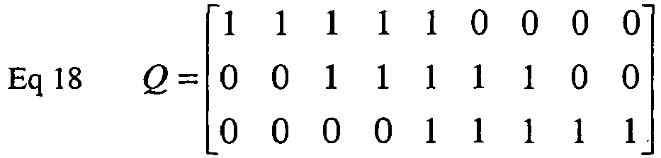
- In all cases, each row of Q contains exactly 2*B+1 ones and the remaining values are 0. Other similar or equivalent Q matrix values or arrangements are possible.
- Note that multiplying the

- In estimation theory, a linear system model is written as:

- For the linear system model in Eq 19, the linear minimum mean squared error estimator (LMMSE) is given by:

- Applied to the present problem, the system equation is:

- The parameter to be estimated, θe , is Hactual. It is being observed through the Q matrix (He = Q) and is being corrupted by a noise vector QN (i.e., we = QN). The noise vector's autocovariance matrix (Cw
e ) is

- Assigning: θ̂e = Hfilt , µθ
e = 0,



- Based on HD, the above equation optimally estimates Hactual among all linear estimators. Instead of filtering

- Further improvements can be made to the implementation cost of the
channel estimation filter 304 by recognizing that the
- A Q' matrix can be created which will be applied to the


- The final form of the channel estimate filtering equation is:

- The parenthesis in the above equation serve to indicate how the implementation of the
channel estimation filter 304 is expected to proceed so as to minimize the implementation cost. First, the Q matrix is applied to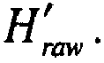


- Next,


- The


final estimates 306 for every subcarrier from 1 through NREF. - Several possible interpolation matrices are available. The simplest interpolation matrix performs linear interpolation based on the nearest two available smoothed channel estimates. A graphical example 600 of the operation of the interpolation matrix is shown in
FIG. 6 . The three solid vertical arrows (subcarriers FIG. 6 represent the estimates produced by applying the

subcarrier 3 is created by averagingsubcarriers subcarrier 2 and 4 (indicated by a dashed line inFIG. 6 ) and calculating the value of that line forsubcarriers Subcarriers subcarriers - For example, if NREF is 9 and B is 2, the interpolation matrix X would be:

- Other interpolation matrices are available. Linear interpolation using two samples may be the best matrix to use in many cases because of the ease of its implementation. Specifically, at most, two real valued multiplications per filtered channel estimate are required with linear interpolation.
- The advantage of the embodiments can be seen by comparing Eq 26 to a filtering equation that does not take advantage of the high correlation between adjacent subcarriers.


- Applying the Q matrix to

- A comparison is made between the application of Msmooth to Hraw in Eq 29 and the application of


- Further implementation reductions are possible when one recognizes that typically, the


- The size of square matrix


- If L is odd, the leftmost L entries of the upper (L+1)/2 rows and the rightmost L entries of the lower (L+1)/2 rows will contain coefficients. For rows (L+1)/2 through W-(L+1)/2-1, the coefficient locations of any particular row will be located in the same positions as the non-zero entries of the previous row, but shifted to the right by one position.
- If L is even, the leftmost L entries of the upper L/2 rows and the rightmost L entries of the lower L/2+1 rows will contain coefficients. For rows L/2 through W-L/2-2, the coefficient locations of any particular row will be located in the same positions as the non-zero entries of the previous row, but shifted to the right by one position.
- The optimal coefficients for Msimp can be solved by calculating


- Therefore, for odd L, the upper (L+1)/2 rows of Mref are assigned to the upper (L+1)/2 rows of Msimp and the lower (L+1)/2 rows of Mref are assigned to the lower (L+1)/2 rows of Msimp. The intermediate rows are all assigned the coefficients of row (L+1)/2-1 of Mref. For even L, the upper L/2 rows of Mref are assigned to the upper L/2 rows of Msimp and the lower L/2 rows of Mref are assigned to the lower L/2 rows of Msimp. The intermediate rows are all assigned the coefficients of row L/2-1 of Mref.
- This extra reduction further reduces the number of multiplications that are necessary. Whereas applying the


- The actual value chosen for L will depend on simulations which tradeoff the performance that may be lost by using a small L value against the simplified implementation cost.
- It should be clear to those skilled in the art that several modifications to the embodiments are possibly without deviating in substance from the embodiments. For example, whereas the exemplary embodiments contained two TOC modules, it should be clear to one skilled in the art that the TOC and PC modules in
system 300 can be freely interchanged and performed in any order. Furthermore, performing a TOC operation with parameter a followed by a TOC operation with parameter b is the same as performing a TOC operation with parameter a+b. In the exemplary embodiments, the TOC operations were separated so as to simplify the narrative explanation of the embodiments. A real world implementation may simply perform a single TOC operation by combining the two TOC operations described in the embodiments. - Furthermore, although the
TOE module 212 was located at the input to thesystem 300, it should be clear to those skilled in the art that different TOE algorithms are available and that some of them operate by examining the output of thesystem DFT 206 so as to determine the time offset. -
Figure 9 is a flow chart representation of aprocess 900 of wireless communications. At 902, a plurality of reference signal transmissions are received on a plurality of subcarriers. The subcarriers that carry reference signals may, e.g., be contiguous or apart from each other and may be known a priori to a receiver. At 904, a plurality of raw channel estimate values may be calculated based on the received plurality of reference signals. The calculations may, e.g., include calculating Hraw, as previously described. At 904, the plurality of raw channel estimates may be processed to obtain a revised channel estimate. In some implementations, the processing may include filtering the raw channel estimates using a linear filter (e.g., represented as a matrix multiplication in the discussion above). The processing may also including interpolating the plurality of raw channel estimate values using an interpolation filter (e.g., averaging), as previously described. In some implementations, the processing may depend on the received signal power and received noise power, as previously discussed. In some implementations, the revised channel estimate may be obtained by processing 2*B+1 subcarrier results, where B is an integer. -
Figure 10 is a block diagram representation of a portion of awireless communications apparatus 1000. The module 1002 (e.g., a receiver) is for receiving a plurality of reference signal transmissions on a plurality of subcarriers. The module 1004 (e.g., a raw channel estimator) is for calculating a plurality of raw channel estimate values based on the received plurality of reference signals. The module 1006 (e.g., a revised channel estimator) is for processing the plurality of raw channel estimate values to obtain a revised channel estimate. Theapparatus 1000 andmodules - It will be appreciated that several techniques have been disclosed to perform channel estimation in an orthogonal frequency domain multiplexing (OFDM) reception operation. In one aspect, multiple raw channel estimates obtained on neighboring subcarriers are filtered to obtain a revised channel estimate, to help improve the receiver performance. In another aspect, the raw channel estimates may be filtered through a smoothing filter, which may be represented as a matrix multiplication operations, with the number of multiplications of the matrix being less than the length of the channel estimate.
- The disclosed and other embodiments and the functional operations described in this document can be implemented in digital electronic circuitry, or in computer software, firmware, or hardware, including the structures disclosed in this document and their structural equivalents, or in combinations of one or more of them. The disclosed and other embodiments can be implemented as one or more computer program products, i.e., one or more modules of computer program instructions encoded on a computer readable medium for execution by, or to control the operation of, data processing apparatus. The computer readable medium can be a machine-readable storage device, a machine-readable storage substrate, a memory device, a composition of matter effecting a machine-readable propagated signal, or a combination of one or more them. The term "data processing apparatus" encompasses all apparatus, devices, and machines for processing data, including by way of example a programmable processor, a computer, or multiple processors or computers. The apparatus can include, in addition to hardware, code that creates an execution environment for the computer program in question, e.g., code that constitutes processor firmware, a protocol stack, a database management system, an operating system, or a combination of one or more of them. A propagated signal is an artificially generated signal, e.g., a machine-generated electrical, optical, or electromagnetic signal, that is generated to encode information for transmission to suitable receiver apparatus.
- A computer program (also known as a program, software, software application, script, or code) can be written in any form of programming language, including compiled or interpreted languages, and it can be deployed in any form, including as a stand alone program or as a module, component, subroutine, or other unit suitable for use in a computing environment. A computer program does not necessarily correspond to a file in a file system. A program can be stored in a portion of a file that holds other programs or data (e.g., one or more scripts stored in a markup language document), in a single file dedicated to the program in question, or in multiple coordinated files (e.g., files that store one or more modules, sub programs, or portions of code). A computer program can be deployed to be executed on one computer or on multiple computers that are located at one site or distributed across multiple sites and interconnected by a communication network.
- The processes and logic flows described in this document can be performed by one or more programmable processors executing one or more computer programs to perform functions by operating on input data and generating output. The processes and logic flows can also be performed by, and apparatus can also be implemented as, special purpose logic circuitry, e.g., an FPGA (field programmable gate array) or an ASIC (application specific integrated circuit).
- Processors suitable for the execution of a computer program include, by way of example, both general and special purpose microprocessors, and any one or more processors of any kind of digital computer. Generally, a processor will receive instructions and data from a read only memory or a random access memory or both. The essential elements of a computer are a processor for performing instructions and one or more memory devices for storing instructions and data. Generally, a computer will also include, or be operatively coupled to receive data from or transfer data to, or both, one or more mass storage devices for storing data, e.g., magnetic, magneto optical disks, or optical disks. However, a computer need not have such devices. Computer readable media suitable for storing computer program instructions and data include all forms of non volatile memory, media and memory devices, including by way of example semiconductor memory devices, e.g., EPROM, EEPROM, and flash memory devices; magnetic disks, e.g., internal hard disks or removable disks; magneto optical disks; and CD ROM and DVD-ROM disks. The processor and the memory can be supplemented by, or incorporated in, special purpose logic circuitry.
- While this document contains many specifics, these should not be construed as limitations on the scope of an invention as defined in the appended claims, but rather as descriptions of features specific to particular embodiments. Certain features that are described in this document in the context of separate embodiments can also be implemented in combination in a single embodiment. Conversely, various features that are described in the context of a single embodiment can also be implemented in multiple embodiments separately or in any suitable sub-combination. Similarly, while operations are depicted in the drawings in a particular order, this should not be understood as requiring that such operations be performed in the particular order shown or in sequential order, or that all illustrated operations be performed, to achieve desirable results. The present invention is defined and limited only by the scope of the appended claims.
Claims (11)
- A channel estimation method in an orthogonal frequency division multiplexing, OFDM, based communication system, said method comprising:receiving (902) a plurality of transmissions of a reference signal on a plurality of subcarriers; andcalculating (904) a plurality of raw channel estimate values based on the received plurality of transmissions of the reference signal, wherein the calculating includes compensating the plurality of transmissions of the reference signal by a first time offset;said method being characterized by:processing (906) the plurality of raw channel estimate values to obtain a revised channel estimate, wherein the processing includes multiplying the plurality of raw channel estimate values by a term whose phase is a function of a second time offset to flatten a phase response of an autocorrelation function of the plurality of raw channel estimate values.
- The method of claim 1, wherein the processing operation comprises:filtering the plurality of raw channel estimate values using a linear filter to reduce an amount of data to be processed; andinterpolating the reduced amount of data of raw channel estimate values using an interpolation filter, wherein the interpolation filter preferably implements linear interpolation.
- The method of claim 1 or 2, wherein the processing operation is based on received signal power and received noise power, and/or wherein the plurality of subcarriers includes (2*B + 1) subcarriers, where B is an integer.
- The method of claim 3, wherein, when the plurality of transmissions of the reference signal comprises Nref reference symbols, then selecting the plurality of subcarriers to include (2*B+1) subcarriers such that B satisfies Nref= L*(B+1) + B, where L is an integer.
- A channel estimation system in an orthogonal frequency division multiplexing, OFDM, based communication system, said system comprising:a receiver for receiving a plurality of transmissions of a reference signal on a plurality of subcarriers; anda raw channel estimator for calculating a plurality of raw channel estimate values based on the received plurality of transmissions of the reference signal, wherein the calculating includes compensating the plurality of transmissions of the reference signal by a first time offset;characterized in that the channel estimation system further comprises:a revised channel estimator for processing the plurality of raw channel estimate values to obtain a revised channel estimate, wherein the processing includes multiplying the plurality of raw channel estimate values by a term whose phase is a function of a second time offset to flatten a phase response of an autocorrelation function of the plurality of raw channel estimate values.
- The system of claim 5, further comprising:a channel estimation filter for filtering the plurality of raw channel estimate values using a linear filter to reduce an amount of data to be processed; andan interpolator for interpolating the reduced amount of data of raw channel estimate values using an interpolation filter, wherein the interpolation filter preferably implements linear interpolation.
- The system of claim 5 or 6, wherein the revised channel estimator is responsive to a received signal power and a received noise power, and/or wherein the plurality of subcarriers includes 2*B + 1 subcarriers, where B is an integer.
- The system of claim 7, wherein, when the plurality of transmissions of the reference signal comprises Nref reference symbols, then the plurality of subcarriers are selected to include (2*B+1) subcarriers such that B satisfies Nref = L*(B+1) + B, where L is an integer.
- A computer program product comprising a non-volatile computer readable medium with computer-executable instructions stored thereupon, the instructions, when executed by a computer, causing said computer to implement a channel estimation method in an orthogonal frequency division multiplexing, OFDM, based communication system, said method, comprising:receiving a plurality of transmissions of a reference signal on a plurality of subcarriers; andcalculating a plurality of raw channel estimate values based on the received plurality of transmissions of the reference signal, wherein the calculating includes compensating the plurality of transmissions of the reference signal by a first time offset;characterized byprocessing the plurality of raw channel estimate values to obtain a revised channel estimate, wherein the processing includes multiplying the plurality of raw channel estimate values by a term whose phase is a function of a second time offset selected to flatten a phase response of an autocorrelation function of the plurality of raw channel estimate values.
- The computer program product of claim 9, wherein the processing operation comprises:filtering the plurality of raw channel estimate values using a linear filter to reduce an amount of data to be processed; andinterpolating the reduced amount of data of raw channel estimate values using an interpolation filter.
- The computer product of claim 10, wherein, when the plurality of transmissions of the reference signal comprises Nref reference symbols, then the plurality subcarriers are selected to include (2*B+1) subcarriers such that B satisfies Nref = L*(B+1) + B, where L is an integer.
Applications Claiming Priority (1)
| Application Number | Priority Date | Filing Date | Title |
|---|---|---|---|
| US201061428222P | 2010-12-29 | 2010-12-29 |
Publications (2)
| Publication Number | Publication Date |
|---|---|
| EP2472806A1 EP2472806A1 (en) | 2012-07-04 |
| EP2472806B1 true EP2472806B1 (en) | 2018-01-31 |
Family
ID=45507330
Family Applications (1)
| Application Number | Title | Priority Date | Filing Date |
|---|---|---|---|
| EP11010291.0A Not-in-force EP2472806B1 (en) | 2010-12-29 | 2011-12-29 | Techniques for improving channel estimation |
Country Status (3)
| Country | Link |
|---|---|
| US (1) | US9258150B2 (en) |
| EP (1) | EP2472806B1 (en) |
| CN (1) | CN102611669B (en) |
Families Citing this family (8)
| Publication number | Priority date | Publication date | Assignee | Title |
|---|---|---|---|---|
| US8995515B2 (en) | 2010-12-29 | 2015-03-31 | Zte Wistron Telecom Ab | Dynamically adjusted OFDM channel estimation filtering in OFDM communications |
| WO2014098737A1 (en) * | 2012-12-17 | 2014-06-26 | Zte Wistron Telecom Ab | Tracking received power in wireless communications |
| US9419770B2 (en) | 2014-03-31 | 2016-08-16 | Huawei Technologies Co., Ltd. | Method and apparatus for asynchronous OFDMA/SC-FDMA |
| US10701685B2 (en) * | 2014-03-31 | 2020-06-30 | Huawei Technologies Co., Ltd. | Method and apparatus for asynchronous OFDMA/SC-FDMA |
| US10531432B2 (en) | 2015-03-25 | 2020-01-07 | Huawei Technologies Co., Ltd. | System and method for resource allocation for sparse code multiple access transmissions |
| US12170584B2 (en) * | 2021-04-01 | 2024-12-17 | Telefonaktiebolaget Lm Ericsson (Publ) | Channel estimation for wireless communication network |
| CN114613383B (en) * | 2022-03-14 | 2023-07-18 | 中国电子科技集团公司第十研究所 | A multi-input speech signal beamforming information complementary method in an airborne environment |
| CN118827284B (en) * | 2023-10-07 | 2025-11-18 | 中国移动通信有限公司研究院 | Channel estimation methods, apparatus, communication equipment and storage media |
Family Cites Families (8)
| Publication number | Priority date | Publication date | Assignee | Title |
|---|---|---|---|---|
| CN1890935A (en) | 2003-12-03 | 2007-01-03 | 澳大利亚电信合作研究中心 | Channel estimation for OFDM systems |
| US7848463B2 (en) | 2005-04-07 | 2010-12-07 | Qualcomm Incorporated | Adaptive time-filtering for channel estimation in OFDM system |
| KR100764012B1 (en) | 2006-12-08 | 2007-10-08 | 한국전자통신연구원 | Channel Estimation Apparatus and Method for Delay Spread of Channel in Mobile Communication System |
| CN101325568B (en) | 2007-06-12 | 2012-02-22 | 华为技术有限公司 | Channel estimation method and apparatus based on OFDM system |
| US7821916B2 (en) * | 2008-04-04 | 2010-10-26 | Newport Media, Inc. | Timing and frequency acquisition for mediaflo systems |
| US8761230B2 (en) * | 2009-06-08 | 2014-06-24 | Adeptence, Llc | Method and apparatus for continuous phase modulation preamble encoding and decoding |
| US8428163B2 (en) * | 2009-07-28 | 2013-04-23 | Broadcom Corporation | Method and system for Doppler spread and delay spread matching with channel estimation by circular convolution in OFDM communication networks |
| US8995515B2 (en) | 2010-12-29 | 2015-03-31 | Zte Wistron Telecom Ab | Dynamically adjusted OFDM channel estimation filtering in OFDM communications |
-
2011
- 2011-12-28 US US13/339,341 patent/US9258150B2/en active Active
- 2011-12-29 EP EP11010291.0A patent/EP2472806B1/en not_active Not-in-force
- 2011-12-29 CN CN201110452499.6A patent/CN102611669B/en not_active Expired - Fee Related
Non-Patent Citations (1)
| Title |
|---|
| None * |
Also Published As
| Publication number | Publication date |
|---|---|
| US20120170630A1 (en) | 2012-07-05 |
| HK1173868A1 (en) | 2013-05-24 |
| CN102611669A (en) | 2012-07-25 |
| EP2472806A1 (en) | 2012-07-04 |
| CN102611669B (en) | 2015-05-06 |
| US9258150B2 (en) | 2016-02-09 |
Similar Documents
| Publication | Publication Date | Title |
|---|---|---|
| US11968144B2 (en) | Channel acquisition using orthogonal time frequency space modulated pilot signals | |
| EP2472805B1 (en) | Dynamically adjusted channel estimation filtering in an OFDM communications system | |
| US9258150B2 (en) | Channel estimation filtering | |
| US6765969B1 (en) | Method and device for multi-user channel estimation | |
| US12621190B2 (en) | Reference signal channel estimation | |
| US8842655B2 (en) | Communication apparatus for multi antenna signal processing | |
| US20080137788A1 (en) | Apparatus and method of estimating channel based on channel delay spread in mobile communication system | |
| EP3086524A1 (en) | Otdoa in lte networks | |
| US9210004B2 (en) | Radio channel estimation | |
| US8594582B2 (en) | Receiver for a radio network and an method for determining a channel estimate for a radio channel | |
| US20090280747A1 (en) | Method and Apparatus for Interference Cancellation in a Wireless Communication System | |
| JP5431498B2 (en) | Receiver and method for mobile communication | |
| KR20160140018A (en) | Method and apparatus for base station synchronization tracking in filter bank multicarrier system | |
| US9100228B2 (en) | Long term evolution (LTE) uplink canonical channel estimation | |
| CN105337907B (en) | A method and device for acquiring channel state information | |
| CN102281216B (en) | Method and device for estimating down channel in orthogonal frequency division multiplexing system | |
| US10931351B2 (en) | Methods and devices for handling transmissions with non-orthogonalty losses | |
| EP4053581A2 (en) | Method and apparatus for obtaining angle information of reference signal | |
| HK1173868B (en) | Channel estimation filtering | |
| CN103428118B (en) | Channel estimation methods and device | |
| WO2025116790A1 (en) | Methods and control units for determining an absent part of a bin coefficient of a first complex frequency-domain signal | |
| EP2728923B1 (en) | Measurement method and apparatus | |
| KR20070080263A (en) | Apparatus and method for removing co-channel interference in broadband wireless communication system supporting space division multiple access |
Legal Events
| Date | Code | Title | Description |
|---|---|---|---|
| 17P | Request for examination filed |
Effective date: 20120102 |
|
| AK | Designated contracting states |
Kind code of ref document: A1 Designated state(s): AL AT BE BG CH CY CZ DE DK EE ES FI FR GB GR HR HU IE IS IT LI LT LU LV MC MK MT NL NO PL PT RO RS SE SI SK SM TR |
|
| AX | Request for extension of the european patent |
Extension state: BA ME |
|
| PUAI | Public reference made under article 153(3) epc to a published international application that has entered the european phase |
Free format text: ORIGINAL CODE: 0009012 |
|
| 17Q | First examination report despatched |
Effective date: 20130417 |
|
| GRAP | Despatch of communication of intention to grant a patent |
Free format text: ORIGINAL CODE: EPIDOSNIGR1 |
|
| INTG | Intention to grant announced |
Effective date: 20170818 |
|
| GRAJ | Information related to disapproval of communication of intention to grant by the applicant or resumption of examination proceedings by the epo deleted |
Free format text: ORIGINAL CODE: EPIDOSDIGR1 |
|
| GRAR | Information related to intention to grant a patent recorded |
Free format text: ORIGINAL CODE: EPIDOSNIGR71 |
|
| GRAS | Grant fee paid |
Free format text: ORIGINAL CODE: EPIDOSNIGR3 |
|
| GRAA | (expected) grant |
Free format text: ORIGINAL CODE: 0009210 |
|
| INTG | Intention to grant announced |
Effective date: 20171220 |
|
| AK | Designated contracting states |
Kind code of ref document: B1 Designated state(s): AL AT BE BG CH CY CZ DE DK EE ES FI FR GB GR HR HU IE IS IT LI LT LU LV MC MK MT NL NO PL PT RO RS SE SI SK SM TR |
|
| REG | Reference to a national code |
Ref country code: GB Ref legal event code: FG4D Ref country code: CH Ref legal event code: EP |
|
| REG | Reference to a national code |
Ref country code: AT Ref legal event code: REF Ref document number: 968280 Country of ref document: AT Kind code of ref document: T Effective date: 20180215 |
|
| REG | Reference to a national code |
Ref country code: IE Ref legal event code: FG4D |
|
| REG | Reference to a national code |
Ref country code: DE Ref legal event code: R096 Ref document number: 602011045429 Country of ref document: DE |
|
| REG | Reference to a national code |
Ref country code: NL Ref legal event code: MP Effective date: 20180131 |
|
| REG | Reference to a national code |
Ref country code: LT Ref legal event code: MG4D |
|
| REG | Reference to a national code |
Ref country code: AT Ref legal event code: MK05 Ref document number: 968280 Country of ref document: AT Kind code of ref document: T Effective date: 20180131 |
|
| PG25 | Lapsed in a contracting state [announced via postgrant information from national office to epo] |
Ref country code: ES Free format text: LAPSE BECAUSE OF FAILURE TO SUBMIT A TRANSLATION OF THE DESCRIPTION OR TO PAY THE FEE WITHIN THE PRESCRIBED TIME-LIMIT Effective date: 20180131 Ref country code: HR Free format text: LAPSE BECAUSE OF FAILURE TO SUBMIT A TRANSLATION OF THE DESCRIPTION OR TO PAY THE FEE WITHIN THE PRESCRIBED TIME-LIMIT Effective date: 20180131 Ref country code: FI Free format text: LAPSE BECAUSE OF FAILURE TO SUBMIT A TRANSLATION OF THE DESCRIPTION OR TO PAY THE FEE WITHIN THE PRESCRIBED TIME-LIMIT Effective date: 20180131 Ref country code: NO Free format text: LAPSE BECAUSE OF FAILURE TO SUBMIT A TRANSLATION OF THE DESCRIPTION OR TO PAY THE FEE WITHIN THE PRESCRIBED TIME-LIMIT Effective date: 20180430 Ref country code: LT Free format text: LAPSE BECAUSE OF FAILURE TO SUBMIT A TRANSLATION OF THE DESCRIPTION OR TO PAY THE FEE WITHIN THE PRESCRIBED TIME-LIMIT Effective date: 20180131 Ref country code: NL Free format text: LAPSE BECAUSE OF FAILURE TO SUBMIT A TRANSLATION OF THE DESCRIPTION OR TO PAY THE FEE WITHIN THE PRESCRIBED TIME-LIMIT Effective date: 20180131 |
|
| PG25 | Lapsed in a contracting state [announced via postgrant information from national office to epo] |
Ref country code: AT Free format text: LAPSE BECAUSE OF FAILURE TO SUBMIT A TRANSLATION OF THE DESCRIPTION OR TO PAY THE FEE WITHIN THE PRESCRIBED TIME-LIMIT Effective date: 20180131 Ref country code: PL Free format text: LAPSE BECAUSE OF FAILURE TO SUBMIT A TRANSLATION OF THE DESCRIPTION OR TO PAY THE FEE WITHIN THE PRESCRIBED TIME-LIMIT Effective date: 20180131 Ref country code: RS Free format text: LAPSE BECAUSE OF FAILURE TO SUBMIT A TRANSLATION OF THE DESCRIPTION OR TO PAY THE FEE WITHIN THE PRESCRIBED TIME-LIMIT Effective date: 20180131 Ref country code: SE Free format text: LAPSE BECAUSE OF FAILURE TO SUBMIT A TRANSLATION OF THE DESCRIPTION OR TO PAY THE FEE WITHIN THE PRESCRIBED TIME-LIMIT Effective date: 20180131 Ref country code: IS Free format text: LAPSE BECAUSE OF FAILURE TO SUBMIT A TRANSLATION OF THE DESCRIPTION OR TO PAY THE FEE WITHIN THE PRESCRIBED TIME-LIMIT Effective date: 20180531 Ref country code: LV Free format text: LAPSE BECAUSE OF FAILURE TO SUBMIT A TRANSLATION OF THE DESCRIPTION OR TO PAY THE FEE WITHIN THE PRESCRIBED TIME-LIMIT Effective date: 20180131 Ref country code: BG Free format text: LAPSE BECAUSE OF FAILURE TO SUBMIT A TRANSLATION OF THE DESCRIPTION OR TO PAY THE FEE WITHIN THE PRESCRIBED TIME-LIMIT Effective date: 20180430 Ref country code: GR Free format text: LAPSE BECAUSE OF FAILURE TO SUBMIT A TRANSLATION OF THE DESCRIPTION OR TO PAY THE FEE WITHIN THE PRESCRIBED TIME-LIMIT Effective date: 20180501 |
|
| PG25 | Lapsed in a contracting state [announced via postgrant information from national office to epo] |
Ref country code: AL Free format text: LAPSE BECAUSE OF FAILURE TO SUBMIT A TRANSLATION OF THE DESCRIPTION OR TO PAY THE FEE WITHIN THE PRESCRIBED TIME-LIMIT Effective date: 20180131 Ref country code: RO Free format text: LAPSE BECAUSE OF FAILURE TO SUBMIT A TRANSLATION OF THE DESCRIPTION OR TO PAY THE FEE WITHIN THE PRESCRIBED TIME-LIMIT Effective date: 20180131 Ref country code: IT Free format text: LAPSE BECAUSE OF FAILURE TO SUBMIT A TRANSLATION OF THE DESCRIPTION OR TO PAY THE FEE WITHIN THE PRESCRIBED TIME-LIMIT Effective date: 20180131 Ref country code: EE Free format text: LAPSE BECAUSE OF FAILURE TO SUBMIT A TRANSLATION OF THE DESCRIPTION OR TO PAY THE FEE WITHIN THE PRESCRIBED TIME-LIMIT Effective date: 20180131 |
|
| REG | Reference to a national code |
Ref country code: DE Ref legal event code: R097 Ref document number: 602011045429 Country of ref document: DE |
|
| PG25 | Lapsed in a contracting state [announced via postgrant information from national office to epo] |
Ref country code: SM Free format text: LAPSE BECAUSE OF FAILURE TO SUBMIT A TRANSLATION OF THE DESCRIPTION OR TO PAY THE FEE WITHIN THE PRESCRIBED TIME-LIMIT Effective date: 20180131 Ref country code: SK Free format text: LAPSE BECAUSE OF FAILURE TO SUBMIT A TRANSLATION OF THE DESCRIPTION OR TO PAY THE FEE WITHIN THE PRESCRIBED TIME-LIMIT Effective date: 20180131 Ref country code: CZ Free format text: LAPSE BECAUSE OF FAILURE TO SUBMIT A TRANSLATION OF THE DESCRIPTION OR TO PAY THE FEE WITHIN THE PRESCRIBED TIME-LIMIT Effective date: 20180131 Ref country code: DK Free format text: LAPSE BECAUSE OF FAILURE TO SUBMIT A TRANSLATION OF THE DESCRIPTION OR TO PAY THE FEE WITHIN THE PRESCRIBED TIME-LIMIT Effective date: 20180131 |
|
| PLBE | No opposition filed within time limit |
Free format text: ORIGINAL CODE: 0009261 |
|
| STAA | Information on the status of an ep patent application or granted ep patent |
Free format text: STATUS: NO OPPOSITION FILED WITHIN TIME LIMIT |
|
| 26N | No opposition filed |
Effective date: 20181102 |
|
| PG25 | Lapsed in a contracting state [announced via postgrant information from national office to epo] |
Ref country code: SI Free format text: LAPSE BECAUSE OF FAILURE TO SUBMIT A TRANSLATION OF THE DESCRIPTION OR TO PAY THE FEE WITHIN THE PRESCRIBED TIME-LIMIT Effective date: 20180131 |
|
| REG | Reference to a national code |
Ref country code: CH Ref legal event code: PL |
|
| PG25 | Lapsed in a contracting state [announced via postgrant information from national office to epo] |
Ref country code: LU Free format text: LAPSE BECAUSE OF NON-PAYMENT OF DUE FEES Effective date: 20181229 Ref country code: MC Free format text: LAPSE BECAUSE OF FAILURE TO SUBMIT A TRANSLATION OF THE DESCRIPTION OR TO PAY THE FEE WITHIN THE PRESCRIBED TIME-LIMIT Effective date: 20180131 |
|
| REG | Reference to a national code |
Ref country code: IE Ref legal event code: MM4A |
|
| REG | Reference to a national code |
Ref country code: BE Ref legal event code: MM Effective date: 20181231 |
|
| PG25 | Lapsed in a contracting state [announced via postgrant information from national office to epo] |
Ref country code: IE Free format text: LAPSE BECAUSE OF NON-PAYMENT OF DUE FEES Effective date: 20181229 |
|
| PG25 | Lapsed in a contracting state [announced via postgrant information from national office to epo] |
Ref country code: BE Free format text: LAPSE BECAUSE OF NON-PAYMENT OF DUE FEES Effective date: 20181231 |
|
| PG25 | Lapsed in a contracting state [announced via postgrant information from national office to epo] |
Ref country code: LI Free format text: LAPSE BECAUSE OF NON-PAYMENT OF DUE FEES Effective date: 20181231 Ref country code: CH Free format text: LAPSE BECAUSE OF NON-PAYMENT OF DUE FEES Effective date: 20181231 |
|
| PG25 | Lapsed in a contracting state [announced via postgrant information from national office to epo] |
Ref country code: MT Free format text: LAPSE BECAUSE OF NON-PAYMENT OF DUE FEES Effective date: 20181229 |
|
| PG25 | Lapsed in a contracting state [announced via postgrant information from national office to epo] |
Ref country code: TR Free format text: LAPSE BECAUSE OF FAILURE TO SUBMIT A TRANSLATION OF THE DESCRIPTION OR TO PAY THE FEE WITHIN THE PRESCRIBED TIME-LIMIT Effective date: 20180131 |
|
| PG25 | Lapsed in a contracting state [announced via postgrant information from national office to epo] |
Ref country code: PT Free format text: LAPSE BECAUSE OF FAILURE TO SUBMIT A TRANSLATION OF THE DESCRIPTION OR TO PAY THE FEE WITHIN THE PRESCRIBED TIME-LIMIT Effective date: 20180131 |
|
| PG25 | Lapsed in a contracting state [announced via postgrant information from national office to epo] |
Ref country code: MK Free format text: LAPSE BECAUSE OF NON-PAYMENT OF DUE FEES Effective date: 20180131 Ref country code: CY Free format text: LAPSE BECAUSE OF FAILURE TO SUBMIT A TRANSLATION OF THE DESCRIPTION OR TO PAY THE FEE WITHIN THE PRESCRIBED TIME-LIMIT Effective date: 20180131 Ref country code: HU Free format text: LAPSE BECAUSE OF FAILURE TO SUBMIT A TRANSLATION OF THE DESCRIPTION OR TO PAY THE FEE WITHIN THE PRESCRIBED TIME-LIMIT; INVALID AB INITIO Effective date: 20111229 |
|
| PGFP | Annual fee paid to national office [announced via postgrant information from national office to epo] |
Ref country code: GB Payment date: 20221110 Year of fee payment: 12 Ref country code: FR Payment date: 20221110 Year of fee payment: 12 Ref country code: DE Payment date: 20221102 Year of fee payment: 12 |
|
| REG | Reference to a national code |
Ref country code: GB Ref legal event code: 732E Free format text: REGISTERED BETWEEN 20240104 AND 20240110 |
|
| REG | Reference to a national code |
Ref country code: DE Ref legal event code: R081 Ref document number: 602011045429 Country of ref document: DE Owner name: ZTE CORPORATION, SHENZHEN, CN Free format text: FORMER OWNER: ZTE WISTRON TELECOM AB, STOCKHOLM, SE |
|
| REG | Reference to a national code |
Ref country code: DE Ref legal event code: R119 Ref document number: 602011045429 Country of ref document: DE |
|
| GBPC | Gb: european patent ceased through non-payment of renewal fee |
Effective date: 20231229 |
|
| PG25 | Lapsed in a contracting state [announced via postgrant information from national office to epo] |
Ref country code: DE Free format text: LAPSE BECAUSE OF NON-PAYMENT OF DUE FEES Effective date: 20240702 |
|
| PG25 | Lapsed in a contracting state [announced via postgrant information from national office to epo] |
Ref country code: GB Free format text: LAPSE BECAUSE OF NON-PAYMENT OF DUE FEES Effective date: 20231229 |
|
| PG25 | Lapsed in a contracting state [announced via postgrant information from national office to epo] |
Ref country code: FR Free format text: LAPSE BECAUSE OF NON-PAYMENT OF DUE FEES Effective date: 20231231 |
|
| PG25 | Lapsed in a contracting state [announced via postgrant information from national office to epo] |
Ref country code: GB Free format text: LAPSE BECAUSE OF NON-PAYMENT OF DUE FEES Effective date: 20231229 Ref country code: FR Free format text: LAPSE BECAUSE OF NON-PAYMENT OF DUE FEES Effective date: 20231231 Ref country code: DE Free format text: LAPSE BECAUSE OF NON-PAYMENT OF DUE FEES Effective date: 20240702 |