EP2472635A1 - Assembled battery and assembled battery manufacturing method - Google Patents
Assembled battery and assembled battery manufacturing method Download PDFInfo
- Publication number
- EP2472635A1 EP2472635A1 EP10811625A EP10811625A EP2472635A1 EP 2472635 A1 EP2472635 A1 EP 2472635A1 EP 10811625 A EP10811625 A EP 10811625A EP 10811625 A EP10811625 A EP 10811625A EP 2472635 A1 EP2472635 A1 EP 2472635A1
- Authority
- EP
- European Patent Office
- Prior art keywords
- voltage detection
- battery pack
- terminals
- battery modules
- battery
- Prior art date
- Legal status (The legal status is an assumption and is not a legal conclusion. Google has not performed a legal analysis and makes no representation as to the accuracy of the status listed.)
- Withdrawn
Links
Images






Classifications
-
- H—ELECTRICITY
- H01—ELECTRIC ELEMENTS
- H01M—PROCESSES OR MEANS, e.g. BATTERIES, FOR THE DIRECT CONVERSION OF CHEMICAL ENERGY INTO ELECTRICAL ENERGY
- H01M10/00—Secondary cells; Manufacture thereof
- H01M10/42—Methods or arrangements for servicing or maintenance of secondary cells or secondary half-cells
- H01M10/48—Accumulators combined with arrangements for measuring, testing or indicating the condition of cells, e.g. the level or density of the electrolyte
-
- H—ELECTRICITY
- H01—ELECTRIC ELEMENTS
- H01M—PROCESSES OR MEANS, e.g. BATTERIES, FOR THE DIRECT CONVERSION OF CHEMICAL ENERGY INTO ELECTRICAL ENERGY
- H01M50/00—Constructional details or processes of manufacture of the non-active parts of electrochemical cells other than fuel cells, e.g. hybrid cells
- H01M50/50—Current conducting connections for cells or batteries
- H01M50/543—Terminals
-
- H—ELECTRICITY
- H01—ELECTRIC ELEMENTS
- H01M—PROCESSES OR MEANS, e.g. BATTERIES, FOR THE DIRECT CONVERSION OF CHEMICAL ENERGY INTO ELECTRICAL ENERGY
- H01M50/00—Constructional details or processes of manufacture of the non-active parts of electrochemical cells other than fuel cells, e.g. hybrid cells
- H01M50/10—Primary casings; Jackets or wrappings
- H01M50/102—Primary casings; Jackets or wrappings characterised by their shape or physical structure
- H01M50/103—Primary casings; Jackets or wrappings characterised by their shape or physical structure prismatic or rectangular
-
- H—ELECTRICITY
- H01—ELECTRIC ELEMENTS
- H01M—PROCESSES OR MEANS, e.g. BATTERIES, FOR THE DIRECT CONVERSION OF CHEMICAL ENERGY INTO ELECTRICAL ENERGY
- H01M50/00—Constructional details or processes of manufacture of the non-active parts of electrochemical cells other than fuel cells, e.g. hybrid cells
- H01M50/20—Mountings; Secondary casings or frames; Racks, modules or packs; Suspension devices; Shock absorbers; Transport or carrying devices; Holders
-
- H—ELECTRICITY
- H01—ELECTRIC ELEMENTS
- H01M—PROCESSES OR MEANS, e.g. BATTERIES, FOR THE DIRECT CONVERSION OF CHEMICAL ENERGY INTO ELECTRICAL ENERGY
- H01M50/00—Constructional details or processes of manufacture of the non-active parts of electrochemical cells other than fuel cells, e.g. hybrid cells
- H01M50/50—Current conducting connections for cells or batteries
-
- H—ELECTRICITY
- H01—ELECTRIC ELEMENTS
- H01M—PROCESSES OR MEANS, e.g. BATTERIES, FOR THE DIRECT CONVERSION OF CHEMICAL ENERGY INTO ELECTRICAL ENERGY
- H01M50/00—Constructional details or processes of manufacture of the non-active parts of electrochemical cells other than fuel cells, e.g. hybrid cells
- H01M50/50—Current conducting connections for cells or batteries
- H01M50/502—Interconnectors for connecting terminals of adjacent batteries; Interconnectors for connecting cells outside a battery casing
- H01M50/503—Interconnectors for connecting terminals of adjacent batteries; Interconnectors for connecting cells outside a battery casing characterised by the shape of the interconnectors
-
- H—ELECTRICITY
- H01—ELECTRIC ELEMENTS
- H01M—PROCESSES OR MEANS, e.g. BATTERIES, FOR THE DIRECT CONVERSION OF CHEMICAL ENERGY INTO ELECTRICAL ENERGY
- H01M50/00—Constructional details or processes of manufacture of the non-active parts of electrochemical cells other than fuel cells, e.g. hybrid cells
- H01M50/50—Current conducting connections for cells or batteries
- H01M50/543—Terminals
- H01M50/547—Terminals characterised by the disposition of the terminals on the cells
- H01M50/55—Terminals characterised by the disposition of the terminals on the cells on the same side of the cell
-
- H—ELECTRICITY
- H01—ELECTRIC ELEMENTS
- H01M—PROCESSES OR MEANS, e.g. BATTERIES, FOR THE DIRECT CONVERSION OF CHEMICAL ENERGY INTO ELECTRICAL ENERGY
- H01M50/00—Constructional details or processes of manufacture of the non-active parts of electrochemical cells other than fuel cells, e.g. hybrid cells
- H01M50/50—Current conducting connections for cells or batteries
- H01M50/543—Terminals
- H01M50/552—Terminals characterised by their shape
- H01M50/553—Terminals adapted for prismatic, pouch or rectangular cells
-
- H—ELECTRICITY
- H01—ELECTRIC ELEMENTS
- H01M—PROCESSES OR MEANS, e.g. BATTERIES, FOR THE DIRECT CONVERSION OF CHEMICAL ENERGY INTO ELECTRICAL ENERGY
- H01M50/00—Constructional details or processes of manufacture of the non-active parts of electrochemical cells other than fuel cells, e.g. hybrid cells
- H01M50/50—Current conducting connections for cells or batteries
- H01M50/569—Constructional details of current conducting connections for detecting conditions inside cells or batteries, e.g. details of voltage sensing terminals
-
- H—ELECTRICITY
- H01—ELECTRIC ELEMENTS
- H01M—PROCESSES OR MEANS, e.g. BATTERIES, FOR THE DIRECT CONVERSION OF CHEMICAL ENERGY INTO ELECTRICAL ENERGY
- H01M10/00—Secondary cells; Manufacture thereof
- H01M10/42—Methods or arrangements for servicing or maintenance of secondary cells or secondary half-cells
- H01M10/48—Accumulators combined with arrangements for measuring, testing or indicating the condition of cells, e.g. the level or density of the electrolyte
- H01M10/482—Accumulators combined with arrangements for measuring, testing or indicating the condition of cells, e.g. the level or density of the electrolyte for several batteries or cells simultaneously or sequentially
-
- H—ELECTRICITY
- H01—ELECTRIC ELEMENTS
- H01M—PROCESSES OR MEANS, e.g. BATTERIES, FOR THE DIRECT CONVERSION OF CHEMICAL ENERGY INTO ELECTRICAL ENERGY
- H01M50/00—Constructional details or processes of manufacture of the non-active parts of electrochemical cells other than fuel cells, e.g. hybrid cells
- H01M50/10—Primary casings; Jackets or wrappings
- H01M50/172—Arrangements of electric connectors penetrating the casing
- H01M50/174—Arrangements of electric connectors penetrating the casing adapted for the shape of the cells
- H01M50/178—Arrangements of electric connectors penetrating the casing adapted for the shape of the cells for pouch or flexible bag cells
-
- Y—GENERAL TAGGING OF NEW TECHNOLOGICAL DEVELOPMENTS; GENERAL TAGGING OF CROSS-SECTIONAL TECHNOLOGIES SPANNING OVER SEVERAL SECTIONS OF THE IPC; TECHNICAL SUBJECTS COVERED BY FORMER USPC CROSS-REFERENCE ART COLLECTIONS [XRACs] AND DIGESTS
- Y02—TECHNOLOGIES OR APPLICATIONS FOR MITIGATION OR ADAPTATION AGAINST CLIMATE CHANGE
- Y02E—REDUCTION OF GREENHOUSE GAS [GHG] EMISSIONS, RELATED TO ENERGY GENERATION, TRANSMISSION OR DISTRIBUTION
- Y02E60/00—Enabling technologies; Technologies with a potential or indirect contribution to GHG emissions mitigation
- Y02E60/10—Energy storage using batteries
-
- Y—GENERAL TAGGING OF NEW TECHNOLOGICAL DEVELOPMENTS; GENERAL TAGGING OF CROSS-SECTIONAL TECHNOLOGIES SPANNING OVER SEVERAL SECTIONS OF THE IPC; TECHNICAL SUBJECTS COVERED BY FORMER USPC CROSS-REFERENCE ART COLLECTIONS [XRACs] AND DIGESTS
- Y10—TECHNICAL SUBJECTS COVERED BY FORMER USPC
- Y10T—TECHNICAL SUBJECTS COVERED BY FORMER US CLASSIFICATION
- Y10T29/00—Metal working
- Y10T29/49—Method of mechanical manufacture
- Y10T29/49002—Electrical device making
- Y10T29/49108—Electric battery cell making
Definitions
- the present invention relates to a battery pack including multiple battery modules each housing a stacked body in which multiple secondary batteries are stacked, and a method of manufacturing the battery pack.
- Japanese Patent Application Publication 2007-59088 discloses the following battery pack as a battery pack formed by combining multiple battery modules each housing multiple secondary batteries.
- a voltage detection line is connected to an electrode tab of each of the secondary batteries housed in each of the battery modules forming the battery pack.
- the battery pack detects the voltages of the secondary batteries via the voltage detection wires, and controls charging and discharging of the secondary batteries housed in the battery modules forming the battery pack on the basis of the detected voltages.
- the voltage detection wires are connected respectively to the electrode tabs of the secondary batteries housed in the battery modules forming the battery pack.
- the number of voltage detection wires is large, and wiring work of the voltage detection wires is thereby cumbersome.
- the number of secondary batteries forming the battery pack is generally increased.
- the number of voltage detection wires is further increased, and wiring work of the voltage detection wires is thereby cumbersome.
- An object of the present invention is to provide a battery pack having multiple battery modules each housing a stacked body in which multiple secondary batteries are stacked, and a method of manufacturing such a battery pack, which are capable of reducing the number of voltage detection wires for detecting voltages of the respective secondary batteries housed in the battery modules forming the battery pack.
- a first aspect of the present invention is a battery pack including: multiple battery modules each including a stacked body in which multiple secondary batteries are stacked, a pair of output terminals, and a voltage detection terminal which is used to detect terminal voltages of the respective secondary batteries and which has a rated current equal to or larger than a rated current of the pair of output terminals; and a bus bar electrically connecting the voltage detection terminals of the multiple battery modules to each other.
- a second aspect of the present invention is a method of manufacturing a battery pack including multiple battery modules including: stacking multiple secondary batteries; obtaining a cell unit by electrically connecting electrode tabs of each of the multiple stacked secondary batteries respectively to a voltage detection terminal and a pair of output terminals, in conformity with an electrical circuit of the multiple battery modules, the voltage detection terminal used to detect terminal voltages of the respective secondary batteries and having a rated current equal to or larger than a rated current of the pair of output terminals; obtaining each of the multiple battery modules by housing the cell unit in a case; and stacking the multiple battery modules and electrically connecting the voltage detection terminals of the multiple battery modules to each other with a bus bar.
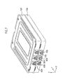
- a battery module 10 of an embodiment is a unit in assembling a battery pack 90 to be described later, and includes a cell unit 20 (see Figs. 2 and 3 ) and a case 50.
- the cell unit 20 includes multiple (four in this example) single cells 30 and the case 50 houses the cell unit 20 therein.
- the cell unit 20 includes four single cells 30A to 30D (a first single cell 30A, a second single cell 30B, a third single cell 30C, and a fourth single cell 30D), spacers 41 to 45 (first spacer 41, second spacer 42, third spacer 43, fourth spacer 44, fifth spacer 45) fitted to both ends of the single cells 30A to 30D, an external output positive terminal 60, an external output negative terminal 70, and a voltage detection terminal 80.
- each of the single cells (cells) 30 is, for example, a flat-shaped lithium ion secondary battery in which a power generation element formed of an electrolyte and an electrode stacked body is housed inside an external member 31 and which has an almost rectangular shape in a plan view.
- the electrode stacked body positive plates and negative plates are alternately stacked with a separator interposed between one another.
- the single cell 30 is a generic term for the single cells 30A to 30D.
- the external member 31 of each single cell 30 is formed of, for example, a laminated film formed by laminating synthetic resin layers on both faces of a metal foil.
- Four sides of the external member 31 are thermal-fusion-bonded to form a flange 32 with the power generation element housed in the external member 31.
- the external member 31 houses the power generation element therein in a sealed manner.
- the positive plates and the negative plates forming the power generation element described above are connected to a positive tab 34 and a negative tab 35 led out to the outside from the external member 31, respectively, in the external member 31.
- the positive tab 34 and the negative tab 35 are both led out to the outside from a short side of the external member 31 on one end side in a longitudinal direction.
- Fixing holes 33 to which fixing pins of the spacers to be described later are respectively inserted are formed in short sides of the flange 32 which are on both end sides in the longitudinal direction.
- the four single cells 30A to 30D form a stacked body in which the four single cells 30A to 30D are stacked to be in direct contact with one another on main surfaces thereof.
- the electrode tabs 34, 35 of the respective single cells 30A to 30D extend outward in a same direction orthogonal to the stacked direction (Z direction) of the single cells 30A to 30D.
- the five spacers 41 to 45 are fitted in end portions of the single cells 30A to 30D where the electrode tabs 34 are led out.
- the spacers 41 to 45 are locked and connected in a state stacked one on top of another, and thus determine a pitch in the stacked direction of the single cells 30A to 30D.
- the flange 32 of the first single cell 30A of the lowest stage is positioned between the first spacer 41 and the second spacer 42.
- the flange 32 of the second single cell 30B is positioned between the second spacer 42 and the third spacer 43
- the flange 32 of the third single cell 30C is positioned between the third spacer 43 and the fourth spacer 44.
- the flange 32 of the fourth single cell 30D is positioned between the fourth spacer 44 and the fifth spacer 45. Note that, although not particularly illustrated, five spacers are fitted to end portions of the four single cells 30A to 30D where no electrode tabs 34, 35 are led out.
- the external output positive terminal 60 and the external output negative terminal 70 being output terminals of the battery module 10 as well as the voltage detection terminal 80 used to detect voltages of the single cells 30A to 30D forming the battery module 10 are led out from the first to fifth spacers 41 to 45.
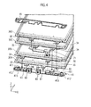
- Fig. 4 is a perspective view showing the single cells 30 housed in the battery module 10.
- the positive tabs 34 of the first single cell 30A and the second single cell 30B are joined to an internal bus bar 61 by ultrasonic welding or the like, the internal bus bar 61 electrically connected to the external output positive terminal 60.
- the negative tabs 35 of the first single cell 30A and the second single cell 30B are joined to an internal bus bar 81 together with the positive tabs 34 of the third single cell 30C and the fourth single cell 30D by ultrasonic welding or the like, the internal bus bar 81 electrically connected to the voltage detection terminal 80.
- the negative tabs 35 of the third single cell 30C and the fourth single cell 30D are joined to an internal bus bar 71 by ultrasonic welding or the like, the internal bus bar 71 electrically connected to the external output negative terminal 70.
- the external output positive terminal 60, the external output negative terminal 70, and the voltage detection terminal 80 are fixed to the first to fifth spacers 41 to 45 fitted to the end portions of the single cells 30A to 30D (specifically, to the flanges 32 on the one end side in the longitudinal direction).
- external forces inputted from the terminals 60, 70, 80 are not transmitted to the positive tabs 34 and the negative tabs 35 of the respective cells via the internal bus bars 61, 71, 81.
- L parallel M series (L, M are each an integer equal to or larger than two) means a circuit configuration in which M blocks (hereinafter, referred to as parallel block) each having L single cells connected in parallel are connected in series.
- the two parallel two series in the embodiment means a circuit configuration in which a parallel block P1 having the single cell 30A and the single cell 30B connected in parallel and a parallel block P2 having the single cell 30C and the single cell 30D connected in parallel are connected to each other in series.
- the voltage detection terminal 80 is a terminal used to detect the voltages of the single cells 30A to 30D forming the battery module 10. Specifically, the voltages of the first single cell 30A and the second single cell 30B can be detected by using the external output positive terminal 60 and the voltage detection terminal 80 to measure a voltage between these terminals. Moreover, the voltages of the third single cell 30C and the fourth single cell 30D can be detected by using the external output negative terminal 70 and the voltage detection terminal 80 to measure a voltage between these terminals.
- the external output positive terminal 60, the external output negative terminal 70, and the voltage detection terminal 80 are formed of terminals through which currents corresponding to battery capacities of the respective single cells 30 housed in the battery module 10 can flow.
- the embodiment uses, as the voltage detection terminal 80, a terminal having a rated current equal to or larger than those of the external output positive terminal 60 and the external output negative terminal 70 (or a terminal having a maximum allowable current equal to or larger than those of the external output positive terminal 60 and the external output negative terminal 70, the maximum allowable current being the maximum value of a current allowed to flow through the terminal).
- any terminal having a rated current equal to or larger than those of the external output positive terminal 60 and the external output negative terminal 70 can be used as the voltage detection terminal 80, manufacturing steps of the battery module 10 can be made simple by using the same terminal as the external output positive terminal 60 and the external output negative terminal 70 (i.e. a terminal having a rated current equal to those of the external output positive terminal 60 and the external output negative terminal 70).
- the first spacer 41 is an almost-plate-shaped member made of a material having an excellent electric insulating property, such as a synthetic resin. As shown in Fig. 4 , two fixing pins 411 to be inserted into the fixing holes 33 of the flange 32 of the first single cell 30A are formed on an upper surface of the first spacer 41. Moreover, sleeve insertion holes 412 to which sleeves 46 (see Fig. 2 ) are to be inserted are formed in both ends of the first spacer 41, respectively. The engagement claws 413 protruding upward are formed near the respective sleeve insertion holes 412. The first spacer 41 and the second spacer 42 are connected to each other by causing the engagement claws 413 to engage with engagement holes (not illustrated) formed in a lower surface of the second spacer 42.
- each of the second to fourth spacers 42 to 44 shown in Fig. 2 is also made of a material having an excellent electric insulating property, such as a synthetic resin, and has fixing pins, sleeve insertion holes, and engagement claws formed therein as in the first spacer 41.
- the fixing pins of the spacers 41 to 44 are inserted into the fixing holes 33 formed in the flanges 32 in both end portions of the single cells 30 in the longitudinal direction, and thus positions of the respective single cells 30A to 30D in a surface direction (X direction or Y direction) are determined.
- the fifth spacer 45 is also made of a material having an excellent electric insulating property, such as a synthetic resin. However, in the fifth spacer 45, no fixing pins or engagement claws are formed, and only sleeve insertion holes are formed. Note that, the second to fourth spacers 42 to 44 are not illustrated in Fig. 4 .
- the case 50 is a case protecting the fragile single cells 30A to 30D of the cell unit 20.
- the case 50 has a lower case 51 having a box shape with a bottom and an opening in an upper portion, and an upper case 52 closing the opening of the lower case 51.
- the lower case 51 and the upper case 52 are seamed together in their edge portions, and are thus fixed to each other. Forming the battery module 10 by housing the cell unit 20 in the case 50 allows the battery pack 90 to be described later to be assembled without worrying about the fragility of the single cells 30A to 30D.
- the upper case 52 has four bolt insertion holes 521 formed at positions corresponding to the sleeves 46 of the cell unit 20, respectively.
- the lower case 51 also has four bolt insertion holes formed at positions corresponding to the sleeves 46 of the cell unit 20, respectively.
- the position of the cell unit 20 is fixed in the case 50 by inserting bolts into the insertion holes 521 of the upper case 52, the sleeves 46 of the cell unit 20, and the insertion holes of the lower case 51.
- three cutouts 511, 512, 513 are formed in a side surface of the lower case 51 on the one end side in the longitudinal direction.
- the external output positive terminal 60, the external output negative terminal 70, and the voltage detection terminal 80 are led out respectively from the cutouts 511, 512, 513.
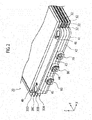
- Fig. 6 is a perspective view showing the battery pack 90 of the embodiment
- Fig. 7 is a view showing the battery pack 90 in a state before external bus bars 910, 920, 930 are attached thereto.
- the battery modules forming the battery pack 90 are respectively a first battery module 10A and a second battery module 10B.
- the battery pack 90 of the embodiment is configured by stacking the first battery module 10A and the second battery module 10B to form a stacked body, and also by electrically connecting external output positive terminals 60A, 60B, external output negative terminals 70A, 70B, and voltage detection terminals 80A, 80B of the battery modules 10A, 10B to each other by the external bus bars 910, 920, 930.
- the external output positive terminals 60A, 60B of the respective battery modules 10A, 10B are electrically connected to each other by the external bus bar 910.
- each of the terminals 60A, 60B. 70A, 70B, 80A, 80B and corresponding one of the external bus bars 910, 920, 930 can be fixed to each other at a female screw portion (not illustrated) formed in each of the terminals 60A, 60B, 70A, 70B, 80A, 80B, by using a fixing bolt.
- each of the terminals 60A, 60B, 70A, 70B, 80A, 80B and corresponding one of the external bus bars 910, 920, 930 are in tight contact with each other, and are thereby electrically connected to each other.
- each of the external bus bars 910, 920, 930 is desirably made of such a material and in such a shape (cross-sectional shape, particularly) that currents corresponding to battery capacities of the single cells 30 housed in the battery modules 10A, 10B can flow therethrough.
- the external bus bars 910, 920, 930 are configured such that a current equal to or larger than rated currents (or the maximum allowable current) of the external output positive terminals 60A, 60B, the external output negative terminals 70A, 70B, and the voltage detection terminals 80A, 80B can flow therethrough without causing defects such as heat generation.
- each of the external bus bars 910, 920, 930 can be formed of a plate-shaped conductive member.
- voltage detection wires 911, 921, 931 are connected respectively to the external bus bars 910, 920, 930, and these wires are connected to a voltage sensor not illustrated.
- Fig. 8 shows an electrical connection configuration of single cells housed in the battery modules 10A, 10B forming the battery pack 90. Note that, in Fig. 8 , single cells forming the battery module 10A are shown as single cells 30E to 30H and single cells forming the battery module 10B are shown as single cells 30I to 30L.
- the battery modules 10A, 10B forming the battery pack 90 have the external output positive terminals 60A, 60B, the external output negative terminals 70A, 70B, and the voltage detection terminals 80A, 80B connected to each other by the external bus bars 910, 920, 930, and thus have a circuit configuration of four parallel two series.
- the four parallel two series in the embodiment means a circuit configuration in which a parallel block P1 and a parallel block P2 are connected in series, the parallel block P1 having the single cell 30E and the single cell 30F in the battery module 10A and the single cell 30I and the single cell 30J in the battery module 10B connected in parallel, the parallel block P2 having the single cell 30G and the single cell 30H of the battery module 10A and the single cell 30K and the single cell 30L of the battery module 10B connected in parallel.
- parallel blocks in one battery module forming a stacked body are connected in parallel respectively to parallel blocks in another battery module forming the stacked body.
- the voltage detection wire 911 connected to the external bus bar 910 and the voltage detection wire 931 connected to the external bus bar 930 are connected to the voltage sensor (not illustrated), and thus the voltages of the single cells 30E, 30F, 30I, 30J can be detected.
- the voltage detection wire 921 connected to the external bus bar 920 and the voltage detection wire 931 connected to the external bus bar 930 are connected to the voltage sensor (not illustrated), and thus the voltages of the single cells 30G 30H, 30K, 30L can be detected.
- the battery modules 10A, 10B forming the battery pack 90 are configured to include the voltage detection terminals 80A, 80B for voltage detection which has a rated currents equal to or larger than those of the external output positive terminals 60A, 60B and the external output negative terminals 70A, 70B, and the voltage detection terminals 80A, 80B of the battery module 10A, 10B are electrically connected to each other by the external bus bar 930.
- the number of voltage detection wires for detecting the terminal voltages of the single cells 30E to 30H and the single cells 301 to 30L forming the battery modules 10A are configured to include the voltage detection terminals 80A, 80B for voltage detection which has a rated currents equal to or larger than those of the external output positive terminals 60A, 60B and the external output negative terminals 70A, 70B, and the voltage detection terminals 80A, 80B of the battery module 10A, 10B are electrically connected to each other by the external bus bar 930.
- the 10B forming the battery pack 90 can be reduced to three (can be reduced to the minimum), which are the voltage detection wires 911, 921, 931.
- wiring work of the voltage detection wires can be made simple.
- the number of voltage detection wires are reduced, the number of pins in a control substrate can be reduced and so on, thus achieving reduction in cost and space.
- the voltage detection terminals 80A, 80B are each formed of a terminal having a rated current equal to or larger than those of the external output positive terminals 60A, 60B and the external output negative terminals 70A. 70B (or having a maximum allowable current equal to or larger than those of the external output positive terminals 60A, 60B and the external output negative terminals 70A, 70B).
- the external bus bar 930 electrically connecting the voltage detection terminals 80A, 80B to each other are configured such that a current equal to or larger than the rated current (or the maximum allowable current) of the voltage detection terminals 80A, 80B can flow therethrough. Accordingly, as described above, even when there is a failure in one of the single cells forming the battery modules 10A, 10B, troubles such as heat generation, breakage, and disconnection of the external bus bar 930 can be effectively prevented from occurring.
- the external output positive terminals 60A, 60B, the external output negative terminals 70A, 70B and the voltage detection terminals 80A, 80B are connected to each other by the external bus bars 910, 920, 930 by using the fixing bolts.
- the terminals 60A, 60B, 70A, 70B, 80A, 80B can be electrically connected to each other more easily.
- the single cells 30 correspond to secondary batteries of the present invention
- the external output positive terminals 60, 60A, 60B and the external output negative terminals 70, 70A, 70B correspond to output terminals of the present invention
- the external bus bars 910, 920, 930 correspond to bus bars of the present invention.
- the battery module 10 having the two parallel two series connection configuration is used, and the battery pack 90 configured by combining the two battery modules 10 to have the connection configuration of four parallel two series is given as an example.
- the connection configuration of the battery modules forming the battery pack and the number of battery modules forming the battery pack are not particularly limited, and can be set as appropriate.
- a configuration as shown in Fig. 9 may be employed.
- the configuration includes 12 battery modules 10, and the terminals 60 of these 12 battery modules 10 are electrically connected to one another by an external bus bars 910a, the terminals 70 thereof are electrically connected to one another by an external bus bars 920a, and the terminals 80 are electrically connected to one another by an external bus bars 930a to form a battery pack 90a of 24 parallel two series.
- voltage detection wires 911a, 921 a, 931a are connected respectively to the external bus bars 910a, 920a, 930a, and these wires are connected to a voltage sensor not illustrated.
- the number of voltage detection terminals 80 to be formed in the battery module 10 is set to a number corresponding to the number of single cells 30 connected in series.
- the number of voltage detection terminals 80 in the battery module 10 is N-1.
- each battery module 10 has a connection configuration of L parallel N series
- the number of battery modules forming the stacked body of the battery pack is K (K is an integer equal to or larger than two)
- the battery pack has a connection configuration of K ⁇ L parallel N series.
- the invention can reduce the number of voltage detection wires for detecting voltages of secondary batteries housed in multiple battery modules forming a battery pack, by electrically connecting voltage detection terminals of the battery modules by a bus bar.
Landscapes
- Chemical & Material Sciences (AREA)
- Chemical Kinetics & Catalysis (AREA)
- Electrochemistry (AREA)
- General Chemical & Material Sciences (AREA)
- Engineering & Computer Science (AREA)
- Manufacturing & Machinery (AREA)
- Battery Mounting, Suspending (AREA)
- Connection Of Batteries Or Terminals (AREA)
- Secondary Cells (AREA)
Abstract
Description
- The present invention relates to a battery pack including multiple battery modules each housing a stacked body in which multiple secondary batteries are stacked, and a method of manufacturing the battery pack.
- Japanese Patent Application Publication
2007-59088 - However, in the battery pack described above, the voltage detection wires are connected respectively to the electrode tabs of the secondary batteries housed in the battery modules forming the battery pack. Thus, the number of voltage detection wires is large, and wiring work of the voltage detection wires is thereby cumbersome. Particularly, in a battery pack using flat-shaped secondary batteries, the number of secondary batteries forming the battery pack is generally increased. Thus, the number of voltage detection wires is further increased, and wiring work of the voltage detection wires is thereby cumbersome.
- An object of the present invention is to provide a battery pack having multiple battery modules each housing a stacked body in which multiple secondary batteries are stacked, and a method of manufacturing such a battery pack, which are capable of reducing the number of voltage detection wires for detecting voltages of the respective secondary batteries housed in the battery modules forming the battery pack.
- A first aspect of the present invention is a battery pack including: multiple battery modules each including a stacked body in which multiple secondary batteries are stacked, a pair of output terminals, and a voltage detection terminal which is used to detect terminal voltages of the respective secondary batteries and which has a rated current equal to or larger than a rated current of the pair of output terminals; and a bus bar electrically connecting the voltage detection terminals of the multiple battery modules to each other.
- In addition, a second aspect of the present invention is a method of manufacturing a battery pack including multiple battery modules including: stacking multiple secondary batteries; obtaining a cell unit by electrically connecting electrode tabs of each of the multiple stacked secondary batteries respectively to a voltage detection terminal and a pair of output terminals, in conformity with an electrical circuit of the multiple battery modules, the voltage detection terminal used to detect terminal voltages of the respective secondary batteries and having a rated current equal to or larger than a rated current of the pair of output terminals; obtaining each of the multiple battery modules by housing the cell unit in a case; and stacking the multiple battery modules and electrically connecting the voltage detection terminals of the multiple battery modules to each other with a bus bar.
-
- [
Fig. 1] Fig. 1 is a perspective view showing a battery module of an embodiment of the present invention. - [
Fig. 2] Fig. 2 is a perspective view of a cell unit of the battery module viewed from a side where tabs are led out. - [
Fig. 3] Fig. 3 is a perspective view showing a single cell housed in the battery module of the embodiment of the present invention. - [
Fig. 4] Fig. 4 is an exploded perspective view showing an inner structure of the battery module of the embodiment of the present invention. - [
Fig. 5] Fig. 5 is a view showing an electrical connection configuration of single cells forming the battery module. - [
Fig. 6] Fig. 6 is a perspective view showing a battery pack of the embodiment of the present invention. - [
Fig. 7] Fig. 7 is a view showing the battery pack of the embodiment the present invention in a state before external bus bars are attached thereto. - [
Fig. 8] Fig. 8 is a view showing an electrical connection configuration of the single cells housed in the battery modules forming the battery pack of the embodiment of the present invention. - [
Fig. 9] Fig. 9 is a plan view showing a battery pack of another embodiment of the present invention. - Specific embodiments to which the present invention is applied are described below in detail with reference to the drawings.
- As shown in
Fig. 1 , abattery module 10 of an embodiment is a unit in assembling abattery pack 90 to be described later, and includes a cell unit 20 (seeFigs. 2 and3 ) and acase 50. Thecell unit 20 includes multiple (four in this example)single cells 30 and thecase 50 houses thecell unit 20 therein. - As shown in
Fig. 2 , thecell unit 20 includes foursingle cells 30A to 30D (a firstsingle cell 30A, a secondsingle cell 30B, a thirdsingle cell 30C, and a fourthsingle cell 30D),spacers 41 to 45 (first spacer 41,second spacer 42,third spacer 43,fourth spacer 44, fifth spacer 45) fitted to both ends of thesingle cells 30A to 30D, an external outputpositive terminal 60, an external outputnegative terminal 70, and avoltage detection terminal 80. - As shown in
Fig. 3 , each of the single cells (cells) 30 is, for example, a flat-shaped lithium ion secondary battery in which a power generation element formed of an electrolyte and an electrode stacked body is housed inside anexternal member 31 and which has an almost rectangular shape in a plan view. In the electrode stacked body, positive plates and negative plates are alternately stacked with a separator interposed between one another. Note that, thesingle cell 30 is a generic term for thesingle cells 30A to 30D. - The
external member 31 of eachsingle cell 30 is formed of, for example, a laminated film formed by laminating synthetic resin layers on both faces of a metal foil. Four sides of theexternal member 31 are thermal-fusion-bonded to form aflange 32 with the power generation element housed in theexternal member 31. Thus, theexternal member 31 houses the power generation element therein in a sealed manner. - Moreover, the positive plates and the negative plates forming the power generation element described above are connected to a
positive tab 34 and anegative tab 35 led out to the outside from theexternal member 31, respectively, in theexternal member 31. Thepositive tab 34 and thenegative tab 35 are both led out to the outside from a short side of theexternal member 31 on one end side in a longitudinal direction. Fixingholes 33 to which fixing pins of the spacers to be described later are respectively inserted are formed in short sides of theflange 32 which are on both end sides in the longitudinal direction. - In the
cell unit 20, the foursingle cells 30A to 30D form a stacked body in which the foursingle cells 30A to 30D are stacked to be in direct contact with one another on main surfaces thereof. Moreover, theelectrode tabs single cells 30A to 30D extend outward in a same direction orthogonal to the stacked direction (Z direction) of thesingle cells 30A to 30D. As shown inFig. 2 , in end portions of thesingle cells 30A to 30D where theelectrode tabs 34 are led out, the fivespacers 41 to 45 are fitted. Thespacers 41 to 45 are locked and connected in a state stacked one on top of another, and thus determine a pitch in the stacked direction of thesingle cells 30A to 30D. - The
flange 32 of the firstsingle cell 30A of the lowest stage is positioned between thefirst spacer 41 and thesecond spacer 42. Moreover, theflange 32 of the secondsingle cell 30B is positioned between thesecond spacer 42 and thethird spacer 43, and theflange 32 of the thirdsingle cell 30C is positioned between thethird spacer 43 and thefourth spacer 44. Furthermore, theflange 32 of the fourthsingle cell 30D is positioned between thefourth spacer 44 and thefifth spacer 45. Note that, although not particularly illustrated, five spacers are fitted to end portions of the foursingle cells 30A to 30D where noelectrode tabs - Moreover, as shown in
Fig. 2 , the external outputpositive terminal 60 and the external outputnegative terminal 70 being output terminals of thebattery module 10 as well as thevoltage detection terminal 80 used to detect voltages of thesingle cells 30A to 30D forming thebattery module 10 are led out from the first tofifth spacers 41 to 45. -
Fig. 4 is a perspective view showing thesingle cells 30 housed in thebattery module 10. As shown inFig. 4 , thepositive tabs 34 of the firstsingle cell 30A and the secondsingle cell 30B are joined to aninternal bus bar 61 by ultrasonic welding or the like, theinternal bus bar 61 electrically connected to the external outputpositive terminal 60. Meanwhile, thenegative tabs 35 of the firstsingle cell 30A and the secondsingle cell 30B are joined to aninternal bus bar 81 together with thepositive tabs 34 of the thirdsingle cell 30C and the fourthsingle cell 30D by ultrasonic welding or the like, theinternal bus bar 81 electrically connected to thevoltage detection terminal 80. Moreover, thenegative tabs 35 of the thirdsingle cell 30C and the fourthsingle cell 30D are joined to aninternal bus bar 71 by ultrasonic welding or the like, theinternal bus bar 71 electrically connected to the external outputnegative terminal 70.
The external outputpositive terminal 60, the external outputnegative terminal 70, and thevoltage detection terminal 80 are fixed to the first tofifth spacers 41 to 45 fitted to the end portions of thesingle cells 30A to 30D (specifically, to theflanges 32 on the one end side in the longitudinal direction). Thus, external forces inputted from theterminals positive tabs 34 and thenegative tabs 35 of the respective cells via theinternal bus bars - The
electrode tabs single cells 30A to 30D are connected to the external outputpositive terminal 60, the external outputnegative terminal 70, and thevoltage detection terminal 80 via theinternal bus bars single cells 30A to 30D form a connection configuration of two parallel two series as shown inFig. 5 . In the description, L parallel M series (L, M are each an integer equal to or larger than two) means a circuit configuration in which M blocks (hereinafter, referred to as parallel block) each having L single cells connected in parallel are connected in series. Accordingly, the two parallel two series in the embodiment means a circuit configuration in which a parallel block P1 having thesingle cell 30A and thesingle cell 30B connected in parallel and a parallel block P2 having thesingle cell 30C and thesingle cell 30D connected in parallel are connected to each other in series. - As shown in
Fig. 5 , thevoltage detection terminal 80 is a terminal used to detect the voltages of thesingle cells 30A to 30D forming thebattery module 10. Specifically, the voltages of the firstsingle cell 30A and the secondsingle cell 30B can be detected by using the external outputpositive terminal 60 and thevoltage detection terminal 80 to measure a voltage between these terminals. Moreover, the voltages of the thirdsingle cell 30C and the fourthsingle cell 30D can be detected by using the external outputnegative terminal 70 and thevoltage detection terminal 80 to measure a voltage between these terminals. - It is desirable that the external output
positive terminal 60, the external outputnegative terminal 70, and thevoltage detection terminal 80 are formed of terminals through which currents corresponding to battery capacities of the respectivesingle cells 30 housed in thebattery module 10 can flow. Particularly, the embodiment uses, as thevoltage detection terminal 80, a terminal having a rated current equal to or larger than those of the external outputpositive terminal 60 and the external output negative terminal 70 (or a terminal having a maximum allowable current equal to or larger than those of the external outputpositive terminal 60 and the external outputnegative terminal 70, the maximum allowable current being the maximum value of a current allowed to flow through the terminal). Although any terminal having a rated current equal to or larger than those of the external outputpositive terminal 60 and the external outputnegative terminal 70 can be used as thevoltage detection terminal 80, manufacturing steps of thebattery module 10 can be made simple by using the same terminal as the external outputpositive terminal 60 and the external output negative terminal 70 (i.e. a terminal having a rated current equal to those of the external outputpositive terminal 60 and the external output negative terminal 70). - The
first spacer 41 is an almost-plate-shaped member made of a material having an excellent electric insulating property, such as a synthetic resin. As shown inFig. 4 , twofixing pins 411 to be inserted into thefixing holes 33 of theflange 32 of the firstsingle cell 30A are formed on an upper surface of thefirst spacer 41. Moreover, sleeve insertion holes 412 to which sleeves 46 (seeFig. 2 ) are to be inserted are formed in both ends of thefirst spacer 41, respectively. Theengagement claws 413 protruding upward are formed near the respective sleeve insertion holes 412. Thefirst spacer 41 and thesecond spacer 42 are connected to each other by causing theengagement claws 413 to engage with engagement holes (not illustrated) formed in a lower surface of thesecond spacer 42. - Moreover, each of the second to
fourth spacers 42 to 44 shown inFig. 2 is also made of a material having an excellent electric insulating property, such as a synthetic resin, and has fixing pins, sleeve insertion holes, and engagement claws formed therein as in thefirst spacer 41. The fixing pins of thespacers 41 to 44 are inserted into the fixing holes 33 formed in theflanges 32 in both end portions of thesingle cells 30 in the longitudinal direction, and thus positions of the respectivesingle cells 30A to 30D in a surface direction (X direction or Y direction) are determined. Meanwhile, thefifth spacer 45 is also made of a material having an excellent electric insulating property, such as a synthetic resin. However, in thefifth spacer 45, no fixing pins or engagement claws are formed, and only sleeve insertion holes are formed. Note that, the second tofourth spacers 42 to 44 are not illustrated inFig. 4 . - Returning to
Fig. 1 , thecell unit 20 configured as described above are housed inside thecase 50 shown inFig. 1 . Thecase 50 is a case protecting the fragilesingle cells 30A to 30D of thecell unit 20. Thecase 50 has alower case 51 having a box shape with a bottom and an opening in an upper portion, and anupper case 52 closing the opening of thelower case 51. Thelower case 51 and theupper case 52 are seamed together in their edge portions, and are thus fixed to each other. Forming thebattery module 10 by housing thecell unit 20 in thecase 50 allows thebattery pack 90 to be described later to be assembled without worrying about the fragility of thesingle cells 30A to 30D. - As shown in
Fig. 1 , theupper case 52 has four bolt insertion holes 521 formed at positions corresponding to thesleeves 46 of thecell unit 20, respectively. Although not particularly illustrated, thelower case 51 also has four bolt insertion holes formed at positions corresponding to thesleeves 46 of thecell unit 20, respectively. The position of thecell unit 20 is fixed in thecase 50 by inserting bolts into the insertion holes 521 of theupper case 52, thesleeves 46 of thecell unit 20, and the insertion holes of thelower case 51. - As shown in
Fig. 1 , threecutouts lower case 51 on the one end side in the longitudinal direction. The external outputpositive terminal 60, the external outputnegative terminal 70, and thevoltage detection terminal 80 are led out respectively from thecutouts - Moreover, in the embodiment, two
battery modules 10 of the embodiment which are configured as described above can be combined as shown inFig. 6 to form thebattery pack 90.Fig. 6 is a perspective view showing thebattery pack 90 of the embodiment, andFig. 7 is a view showing thebattery pack 90 in a state before external bus bars 910, 920, 930 are attached thereto. Note that, inFigs. 6 and7 , the battery modules forming thebattery pack 90 are respectively afirst battery module 10A and asecond battery module 10B. - As shown in
Figs. 6 and7 , thebattery pack 90 of the embodiment is configured by stacking thefirst battery module 10A and thesecond battery module 10B to form a stacked body, and also by electrically connecting external outputpositive terminals negative terminals voltage detection terminals battery modules positive terminals respective battery modules external bus bar 910. the external outputnegative terminals 70Aexternal bus bar 920, and thevoltage detection terminals external bus bar 930. Note that, each of theterminals terminals terminals - Note that, in the embodiment, each of the external bus bars 910, 920, 930 is desirably made of such a material and in such a shape (cross-sectional shape, particularly) that currents corresponding to battery capacities of the
single cells 30 housed in thebattery modules positive terminals negative terminals voltage detection terminals Fig. 6 , each of the external bus bars 910, 920, 930 can be formed of a plate-shaped conductive member. - Moreover, as shown in
Fig. 6 ,voltage detection wires -
Fig. 8 shows an electrical connection configuration of single cells housed in thebattery modules battery pack 90. Note that, inFig. 8 , single cells forming thebattery module 10A are shown assingle cells 30E to 30H and single cells forming thebattery module 10B are shown as single cells 30I to 30L. - As shown in
Fig. 8 , thebattery modules battery pack 90 have the external outputpositive terminals negative terminals voltage detection terminals single cell 30E and thesingle cell 30F in thebattery module 10A and the single cell 30I and thesingle cell 30J in thebattery module 10B connected in parallel, the parallel block P2 having thesingle cell 30G and thesingle cell 30H of thebattery module 10A and thesingle cell 30K and thesingle cell 30L of thebattery module 10B connected in parallel. In other words, in thebattery pack 90, parallel blocks in one battery module forming a stacked body are connected in parallel respectively to parallel blocks in another battery module forming the stacked body. - Then, the
voltage detection wire 911 connected to theexternal bus bar 910 and thevoltage detection wire 931 connected to theexternal bus bar 930 are connected to the voltage sensor (not illustrated), and thus the voltages of thesingle cells voltage detection wire 921 connected to theexternal bus bar 920 and thevoltage detection wire 931 connected to theexternal bus bar 930 are connected to the voltage sensor (not illustrated), and thus the voltages of thesingle cells 30G - As described above, in the embodiment, the
battery modules battery pack 90 are configured to include thevoltage detection terminals positive terminals negative terminals voltage detection terminals battery module external bus bar 930. Thus, in the embodiment, the number of voltage detection wires for detecting the terminal voltages of thesingle cells 30E to 30H and thesingle cells 301 to 30L forming thebattery modules 10A. 10B forming thebattery pack 90 can be reduced to three (can be reduced to the minimum), which are thevoltage detection wires - Furthermore, in the embodiment, the
voltage detection terminals positive terminals negative terminals 70A. 70B (or having a maximum allowable current equal to or larger than those of the external outputpositive terminals negative terminals battery module 10A (or 10B) among thesingle cells 30E to 30H forming thebattery module 10A and thesingle cells 301 to 30L forming thebattery module 10B, and this failure causes increase in the amount of currents flowing to the working single cells, particularly to the single cells forming theother battery module 10B (or 10A). Even in such a case, troubles such as heat generation and breakage of thevoltage detection terminal 80B (or 80A) of theother battery module 10B (or 10A) can be effectively prevented from occurring. Particularly, when the single cell forming thebattery modules voltage detection terminal 80 can be effectively prevented from occurring. - Moreover, in the embodiment, the
external bus bar 930 electrically connecting thevoltage detection terminals voltage detection terminals battery modules external bus bar 930 can be effectively prevented from occurring. - Furthermore, in the embodiment, the external output
positive terminals negative terminals voltage detection terminals terminals - Note that, in the embodiment described above, the
single cells 30 correspond to secondary batteries of the present invention, the external outputpositive terminals negative terminals - The embodiment of the present invention has been described above. However, the embodiment is merely an example described to facilitate the understanding of the present invention, and the present invention is not limited to the embodiment. The elements disclosed in the embodiment described above are intended to include any types of design modifications and equivalents pertaining to the technical scope of the invention.
- For example, in the embodiment described above, the
battery module 10 having the two parallel two series connection configuration is used, and thebattery pack 90 configured by combining the twobattery modules 10 to have the connection configuration of four parallel two series is given as an example. However, the connection configuration of the battery modules forming the battery pack and the number of battery modules forming the battery pack are not particularly limited, and can be set as appropriate. For example, a configuration as shown inFig. 9 may be employed. Specifically, the configuration includes 12battery modules 10, and theterminals 60 of these 12battery modules 10 are electrically connected to one another by anexternal bus bars 910a, theterminals 70 thereof are electrically connected to one another by anexternal bus bars 920a, and theterminals 80 are electrically connected to one another by anexternal bus bars 930a to form abattery pack 90a of 24 parallel two series. Note that, as shown inFig. 9 , in thebattery pack 90a,voltage detection wires external bus bars - Note that, for example, when the number of
single cells 30 forming thebattery module 10 which are connected in series is three in the embodiment described above, the number ofvoltage detection terminals 80 to be formed in thebattery module 10 is set to a number corresponding to the number ofsingle cells 30 connected in series. For example, when the number ofsingle cells 30 connected in series is N (N is an integer equal to or larger than three), the number ofvoltage detection terminals 80 in thebattery module 10 is N-1. Here, eachbattery module 10 has a connection configuration of L parallel N series, and when the number of battery modules forming the stacked body of the battery pack is K (K is an integer equal to or larger than two), the battery pack has a connection configuration of K×L parallel N series. - The present application claims the priority based on Japanese Patent Application No.
2009-197734 filed on August 28, 2009 - The invention can reduce the number of voltage detection wires for detecting voltages of secondary batteries housed in multiple battery modules forming a battery pack, by electrically connecting voltage detection terminals of the battery modules by a bus bar.
-
- 10, 10A, 10B
- BATTERY MODULE
- 20
- CELL UNIT
-
30A TO 30D - SINGLE CELL
- 34
- POSITIVE TAB
- 35
- NEGATIVE TAB
- 50
- CASE
- 60, 60A, 60B
- EXTERNAL OUTPUT POSITIVE TERMINAL
- 61
- INTERNAL BUS BAR
- 70, 70A, 70B
- EXTERNAL OUTPUT NEGATIVE TERMINAL
- 71
- INTERNAL BUS BAR
- 80, 80A, 80B
- VOLTAGE DETECTION TERMINAL
- 81
- INTERNAL BUS BAR
- 90, 90A
- BATTERY PACK
- 910, 920, 930
- EXTERNAL BUS BAR
- 911,921,931
- VOLTAGE DETECTION WIRE
Claims (5)
- A battery pack comprising:a plurality of battery modules each including a stacked body in which a plurality of secondary batteries are stacked, a pair of output terminals, and a voltage detection terminal which is used to detect terminal voltages of the respective secondary batteries and which has a rated current equal to or larger than a rated current of the pair of output terminals; anda bus bar electrically connecting the voltage detection terminals of the plurality of battery modules to each other.
- The battery pack according to claim 1, wherein the bus bar is a bus bar capable of conducting a current equal to or larger than the rated current of the voltage detection terminal.
- The battery pack according to claim 1 or 2, wherein the bus bar is formed of a plate-shaped conductive member.
- The battery pack according to any one of claims 1 to 3, wherein one output terminals of the respective pairs of output terminals of the plurality of battery modules are connected to each other and the other output terminals of the respective pairs of output terminals are connected to each other respectively by bus bars different from the bus bar electrically connecting the voltage detection terminals to each other.
- A method of manufacturing a battery pack including a plurality of battery modules comprising:stacking a plurality of secondary batteries;obtaining a cell unit by electrically connecting electrode tabs of each of the plurality of stacked secondary batteries respectively to a voltage detection terminal and a pair of output terminals, in conformity with an electrical circuit of the plurality of battery modules, the voltage detection terminal used to detect terminal voltages of the respective secondary batteries and having a rated current equal to or larger than a rated current of the pair of output terminals;obtaining each of the plurality of battery modules by housing the cell unit in a case; andstacking the plurality of battery modules and electrically connecting the voltage detection terminals of the plurality of battery modules to each other with a bus bar.
Applications Claiming Priority (2)
| Application Number | Priority Date | Filing Date | Title |
|---|---|---|---|
| JP2009197734A JP4877373B2 (en) | 2009-08-28 | 2009-08-28 | Assembled battery and manufacturing method of assembled battery |
| PCT/JP2010/061914 WO2011024574A1 (en) | 2009-08-28 | 2010-07-14 | Assembled battery and assembled battery manufacturing method |
Publications (2)
| Publication Number | Publication Date |
|---|---|
| EP2472635A1 true EP2472635A1 (en) | 2012-07-04 |
| EP2472635A4 EP2472635A4 (en) | 2013-09-18 |
Family
ID=43627685
Family Applications (1)
| Application Number | Title | Priority Date | Filing Date |
|---|---|---|---|
| EP10811625.2A Withdrawn EP2472635A4 (en) | 2009-08-28 | 2010-07-14 | Assembled battery and assembled battery manufacturing method |
Country Status (10)
| Country | Link |
|---|---|
| US (1) | US20120141847A1 (en) |
| EP (1) | EP2472635A4 (en) |
| JP (1) | JP4877373B2 (en) |
| KR (1) | KR101249184B1 (en) |
| CN (1) | CN102473879A (en) |
| BR (1) | BR112012004425A2 (en) |
| MX (1) | MX2012001972A (en) |
| MY (1) | MY154198A (en) |
| RU (1) | RU2490755C1 (en) |
| WO (1) | WO2011024574A1 (en) |
Cited By (2)
| Publication number | Priority date | Publication date | Assignee | Title |
|---|---|---|---|---|
| CN104078636A (en) * | 2013-03-27 | 2014-10-01 | 丰田合成株式会社 | Battery device |
| EP2911217A1 (en) * | 2014-02-19 | 2015-08-26 | Delta Electronics, Inc. | Cell and manufacture method thereof |
Families Citing this family (20)
| Publication number | Priority date | Publication date | Assignee | Title |
|---|---|---|---|---|
| JP5500518B2 (en) * | 2009-06-10 | 2014-05-21 | 矢崎総業株式会社 | Battery terminal with current sensor |
| JP5737046B2 (en) * | 2011-08-10 | 2015-06-17 | 株式会社オートネットワーク技術研究所 | Battery wiring module |
| JP5836147B2 (en) * | 2012-02-08 | 2015-12-24 | 株式会社ニフコ | Cover for external connection of battery |
| JP5606480B2 (en) * | 2012-03-22 | 2014-10-15 | 株式会社東芝 | Battery and battery manufacturing method |
| JP6135246B2 (en) * | 2013-03-29 | 2017-05-31 | 株式会社Gsユアサ | Power storage device |
| KR102063601B1 (en) * | 2013-06-21 | 2020-01-08 | 에스케이이노베이션 주식회사 | battery module |
| US10084218B2 (en) | 2014-05-09 | 2018-09-25 | Lg Chem, Ltd. | Battery pack and method of assembling the battery pack |
| US10770762B2 (en) | 2014-05-09 | 2020-09-08 | Lg Chem, Ltd. | Battery module and method of assembling the battery module |
| US9786894B2 (en) * | 2014-11-03 | 2017-10-10 | Lg Chem, Ltd. | Battery pack |
| EP3131171B1 (en) * | 2014-11-11 | 2019-01-30 | Guangdong Oppo Mobile Telecommunications Corp., Ltd | Power adaptor, terminal and charging system |
| US20170025661A1 (en) * | 2015-07-23 | 2017-01-26 | Ford Global Technologies, Llc | Sensor lead securing assembly and method |
| US9960465B2 (en) | 2015-07-30 | 2018-05-01 | Lg Chem, Ltd. | Battery pack |
| EP3367462A4 (en) * | 2015-10-22 | 2018-09-26 | Nissan Motor Co., Ltd. | Battery pack |
| JP6479924B1 (en) | 2017-10-03 | 2019-03-06 | カルソニックカンセイ株式会社 | Manufacturing method of assembled battery and assembled battery |
| JP6567620B2 (en) | 2017-10-03 | 2019-08-28 | カルソニックカンセイ株式会社 | Manufacturing method of assembled battery and assembled battery |
| KR102699573B1 (en) * | 2019-05-14 | 2024-08-27 | 에스케이온 주식회사 | Bettery module |
| CN111564660A (en) * | 2020-06-19 | 2020-08-21 | 义乌易换骑电池有限公司 | Lithium battery pack capable of preventing voltage acquisition interference |
| JP7647261B2 (en) * | 2021-04-08 | 2025-03-18 | トヨタ自動車株式会社 | Battery pack manufacturing method |
| KR102637525B1 (en) * | 2021-10-26 | 2024-02-19 | 주식회사 엘지에너지솔루션 | Battery moule and battery pack including the same |
| JP7825710B2 (en) * | 2022-05-25 | 2026-03-06 | 日産自動車株式会社 | Battery module |
Family Cites Families (17)
| Publication number | Priority date | Publication date | Assignee | Title |
|---|---|---|---|---|
| SU121828A1 (en) * | 1958-05-30 | 1958-11-30 | Н.М. Емельянов | Device for joining positive lead battery plates during their formation |
| RU2187865C2 (en) * | 1997-01-13 | 2002-08-20 | Овоник Бэттери Компани, Инк. | Mechanical and thermal perfection of nickel-cadmium-hybrid batteries, battery modules and blocks of batteries |
| KR100456857B1 (en) * | 2002-11-25 | 2004-11-10 | 현대자동차주식회사 | Cell connecting device of hybrid electric vehicle |
| JP4581326B2 (en) * | 2002-12-27 | 2010-11-17 | 日産自動車株式会社 | Multilayer battery manufacturing equipment |
| JP4238645B2 (en) * | 2003-06-12 | 2009-03-18 | 日産自動車株式会社 | Bipolar battery |
| JP3894182B2 (en) * | 2003-10-10 | 2007-03-14 | 日産自動車株式会社 | Assembled battery |
| BRPI0519442B8 (en) * | 2004-12-24 | 2023-01-10 | Lg Chemical Ltd | SET OF SENSOR PLATES MOUNTED ON A BATTERY MODULE AND BATTERY MODULE INCLUDING SAID SET |
| KR100891079B1 (en) * | 2005-02-07 | 2009-03-30 | 주식회사 엘지화학 | Battery Cartridge Connection System for Battery Module |
| JP4857710B2 (en) * | 2005-06-01 | 2012-01-18 | 日産自動車株式会社 | Battery pack and vehicle equipped with the same |
| JP4894198B2 (en) | 2005-08-22 | 2012-03-14 | 日産自動車株式会社 | Assembled battery |
| JP2007265945A (en) * | 2006-03-30 | 2007-10-11 | Tokyo R & D Co Ltd | Lamination cell accumulation type battery and battery module |
| US7960943B2 (en) * | 2006-11-17 | 2011-06-14 | Cobasys, Llc | Modular battery system having battery monitoring and data collection capability |
| JP4379467B2 (en) * | 2006-12-11 | 2009-12-09 | 日産自動車株式会社 | Battery module |
| JP5018203B2 (en) * | 2007-04-19 | 2012-09-05 | パナソニック株式会社 | Power storage unit |
| JP2009112111A (en) * | 2007-10-30 | 2009-05-21 | Toshiba Corp | Battery pack, charger and battery pack system |
| CA2646925A1 (en) * | 2007-12-12 | 2009-06-12 | Westward Industries Ltd. | Battery management system |
| JP2009197734A (en) | 2008-02-22 | 2009-09-03 | Toyota Motor Corp | Method of converting solar heat energy |
-
2009
- 2009-08-28 JP JP2009197734A patent/JP4877373B2/en not_active Expired - Fee Related
-
2010
- 2010-07-14 US US13/390,189 patent/US20120141847A1/en not_active Abandoned
- 2010-07-14 EP EP10811625.2A patent/EP2472635A4/en not_active Withdrawn
- 2010-07-14 MX MX2012001972A patent/MX2012001972A/en active IP Right Grant
- 2010-07-14 KR KR1020127004000A patent/KR101249184B1/en not_active Expired - Fee Related
- 2010-07-14 BR BR112012004425A patent/BR112012004425A2/en not_active IP Right Cessation
- 2010-07-14 MY MYPI2012000666A patent/MY154198A/en unknown
- 2010-07-14 WO PCT/JP2010/061914 patent/WO2011024574A1/en not_active Ceased
- 2010-07-14 CN CN2010800362765A patent/CN102473879A/en active Pending
- 2010-07-14 RU RU2012107105/07A patent/RU2490755C1/en not_active IP Right Cessation
Cited By (3)
| Publication number | Priority date | Publication date | Assignee | Title |
|---|---|---|---|---|
| CN104078636A (en) * | 2013-03-27 | 2014-10-01 | 丰田合成株式会社 | Battery device |
| EP2911217A1 (en) * | 2014-02-19 | 2015-08-26 | Delta Electronics, Inc. | Cell and manufacture method thereof |
| US10205140B2 (en) | 2014-02-19 | 2019-02-12 | Delta Electronics, Inc. | Cell and manufacture method thereof |
Also Published As
| Publication number | Publication date |
|---|---|
| US20120141847A1 (en) | 2012-06-07 |
| JP2011049080A (en) | 2011-03-10 |
| KR101249184B1 (en) | 2013-04-03 |
| MY154198A (en) | 2015-05-15 |
| KR20120048631A (en) | 2012-05-15 |
| BR112012004425A2 (en) | 2017-05-30 |
| EP2472635A4 (en) | 2013-09-18 |
| CN102473879A (en) | 2012-05-23 |
| WO2011024574A1 (en) | 2011-03-03 |
| MX2012001972A (en) | 2012-03-29 |
| JP4877373B2 (en) | 2012-02-15 |
| RU2490755C1 (en) | 2013-08-20 |
Similar Documents
| Publication | Publication Date | Title |
|---|---|---|
| US20120141847A1 (en) | Battery pack and method for manufacturing battery pack | |
| EP2482361B1 (en) | Battery pack | |
| KR100920207B1 (en) | Power switching module for manufacturing battery module assembly | |
| US9640790B2 (en) | Middle or large-sized battery module | |
| JP2011243561A (en) | Battery pack | |
| EP2662922B1 (en) | Battery pack provided with stable measurement means | |
| KR101765024B1 (en) | Battery pack | |
| CN105612630A (en) | Battery cell, battery module and motor vehicle with prismatic or cylindrical housing | |
| CN116247384A (en) | battery stack | |
| CN104103801B (en) | battery module | |
| KR102760922B1 (en) | Batteries, electrical appliances and methods for manufacturing batteries | |
| KR20180124090A (en) | Battery and battery manufacturing method | |
| EP2874204B1 (en) | Battery assembly | |
| US12494521B2 (en) | Voltage detection line and voltage detection line module | |
| KR101652653B1 (en) | Battery module and battery pack | |
| EP3496179A1 (en) | Connector for a battery pack | |
| CN111033811B (en) | Battery laminate | |
| KR101822879B1 (en) | Secondary battery module | |
| US12463291B2 (en) | Pouch-type battery pack having folding structure and manufacturing method there-of | |
| WO2013108786A1 (en) | Power supply device, vehicle provided with same, electrical storage device, and circuit board for power supply device |
Legal Events
| Date | Code | Title | Description |
|---|---|---|---|
| PUAI | Public reference made under article 153(3) epc to a published international application that has entered the european phase |
Free format text: ORIGINAL CODE: 0009012 |
|
| 17P | Request for examination filed |
Effective date: 20120227 |
|
| AK | Designated contracting states |
Kind code of ref document: A1 Designated state(s): AL AT BE BG CH CY CZ DE DK EE ES FI FR GB GR HR HU IE IS IT LI LT LU LV MC MK MT NL NO PL PT RO SE SI SK SM TR |
|
| DAX | Request for extension of the european patent (deleted) | ||
| A4 | Supplementary search report drawn up and despatched |
Effective date: 20130819 |
|
| RIC1 | Information provided on ipc code assigned before grant |
Ipc: H01M 10/48 20060101ALI20130812BHEP Ipc: H01M 2/20 20060101ALI20130812BHEP Ipc: H01M 2/02 20060101ALN20130812BHEP Ipc: H01M 2/10 20060101AFI20130812BHEP Ipc: G01R 31/00 20060101ALI20130812BHEP Ipc: H01M 2/30 20060101ALI20130812BHEP |
|
| STAA | Information on the status of an ep patent application or granted ep patent |
Free format text: STATUS: THE APPLICATION HAS BEEN WITHDRAWN |
|
| 18W | Application withdrawn |
Effective date: 20140922 |