EP2472633A1 - Battery module - Google Patents
Battery module Download PDFInfo
- Publication number
- EP2472633A1 EP2472633A1 EP20120150051 EP12150051A EP2472633A1 EP 2472633 A1 EP2472633 A1 EP 2472633A1 EP 20120150051 EP20120150051 EP 20120150051 EP 12150051 A EP12150051 A EP 12150051A EP 2472633 A1 EP2472633 A1 EP 2472633A1
- Authority
- EP
- European Patent Office
- Prior art keywords
- head
- protrusion
- barrier
- plate
- battery module
- Prior art date
- Legal status (The legal status is an assumption and is not a legal conclusion. Google has not performed a legal analysis and makes no representation as to the accuracy of the status listed.)
- Granted
Links
Images


Classifications
-
- H—ELECTRICITY
- H01—ELECTRIC ELEMENTS
- H01M—PROCESSES OR MEANS, e.g. BATTERIES, FOR THE DIRECT CONVERSION OF CHEMICAL ENERGY INTO ELECTRICAL ENERGY
- H01M50/00—Constructional details or processes of manufacture of the non-active parts of electrochemical cells other than fuel cells, e.g. hybrid cells
- H01M50/20—Mountings; Secondary casings or frames; Racks, modules or packs; Suspension devices; Shock absorbers; Transport or carrying devices; Holders
- H01M50/258—Modular batteries; Casings provided with means for assembling
-
- H—ELECTRICITY
- H01—ELECTRIC ELEMENTS
- H01M—PROCESSES OR MEANS, e.g. BATTERIES, FOR THE DIRECT CONVERSION OF CHEMICAL ENERGY INTO ELECTRICAL ENERGY
- H01M10/00—Secondary cells; Manufacture thereof
- H01M10/60—Heating or cooling; Temperature control
-
- H—ELECTRICITY
- H01—ELECTRIC ELEMENTS
- H01M—PROCESSES OR MEANS, e.g. BATTERIES, FOR THE DIRECT CONVERSION OF CHEMICAL ENERGY INTO ELECTRICAL ENERGY
- H01M10/00—Secondary cells; Manufacture thereof
- H01M10/60—Heating or cooling; Temperature control
- H01M10/61—Types of temperature control
- H01M10/613—Cooling or keeping cold
-
- H—ELECTRICITY
- H01—ELECTRIC ELEMENTS
- H01M—PROCESSES OR MEANS, e.g. BATTERIES, FOR THE DIRECT CONVERSION OF CHEMICAL ENERGY INTO ELECTRICAL ENERGY
- H01M10/00—Secondary cells; Manufacture thereof
- H01M10/60—Heating or cooling; Temperature control
- H01M10/62—Heating or cooling; Temperature control specially adapted for specific applications
- H01M10/625—Vehicles
-
- H—ELECTRICITY
- H01—ELECTRIC ELEMENTS
- H01M—PROCESSES OR MEANS, e.g. BATTERIES, FOR THE DIRECT CONVERSION OF CHEMICAL ENERGY INTO ELECTRICAL ENERGY
- H01M10/00—Secondary cells; Manufacture thereof
- H01M10/60—Heating or cooling; Temperature control
- H01M10/64—Heating or cooling; Temperature control characterised by the shape of the cells
- H01M10/647—Prismatic or flat cells, e.g. pouch cells
-
- H—ELECTRICITY
- H01—ELECTRIC ELEMENTS
- H01M—PROCESSES OR MEANS, e.g. BATTERIES, FOR THE DIRECT CONVERSION OF CHEMICAL ENERGY INTO ELECTRICAL ENERGY
- H01M10/00—Secondary cells; Manufacture thereof
- H01M10/60—Heating or cooling; Temperature control
- H01M10/65—Means for temperature control structurally associated with the cells
- H01M10/655—Solid structures for heat exchange or heat conduction
- H01M10/6551—Surfaces specially adapted for heat dissipation or radiation, e.g. fins or coatings
-
- H—ELECTRICITY
- H01—ELECTRIC ELEMENTS
- H01M—PROCESSES OR MEANS, e.g. BATTERIES, FOR THE DIRECT CONVERSION OF CHEMICAL ENERGY INTO ELECTRICAL ENERGY
- H01M10/00—Secondary cells; Manufacture thereof
- H01M10/60—Heating or cooling; Temperature control
- H01M10/65—Means for temperature control structurally associated with the cells
- H01M10/655—Solid structures for heat exchange or heat conduction
- H01M10/6554—Rods or plates
- H01M10/6555—Rods or plates arranged between the cells
-
- H—ELECTRICITY
- H01—ELECTRIC ELEMENTS
- H01M—PROCESSES OR MEANS, e.g. BATTERIES, FOR THE DIRECT CONVERSION OF CHEMICAL ENERGY INTO ELECTRICAL ENERGY
- H01M10/00—Secondary cells; Manufacture thereof
- H01M10/60—Heating or cooling; Temperature control
- H01M10/65—Means for temperature control structurally associated with the cells
- H01M10/656—Means for temperature control structurally associated with the cells characterised by the type of heat-exchange fluid
- H01M10/6561—Gases
- H01M10/6563—Gases with forced flow, e.g. by blowers
-
- H—ELECTRICITY
- H01—ELECTRIC ELEMENTS
- H01M—PROCESSES OR MEANS, e.g. BATTERIES, FOR THE DIRECT CONVERSION OF CHEMICAL ENERGY INTO ELECTRICAL ENERGY
- H01M50/00—Constructional details or processes of manufacture of the non-active parts of electrochemical cells other than fuel cells, e.g. hybrid cells
- H01M50/50—Current conducting connections for cells or batteries
- H01M50/572—Means for preventing undesired use or discharge
- H01M50/574—Devices or arrangements for the interruption of current
- H01M50/578—Devices or arrangements for the interruption of current in response to pressure
-
- H—ELECTRICITY
- H01—ELECTRIC ELEMENTS
- H01M—PROCESSES OR MEANS, e.g. BATTERIES, FOR THE DIRECT CONVERSION OF CHEMICAL ENERGY INTO ELECTRICAL ENERGY
- H01M50/00—Constructional details or processes of manufacture of the non-active parts of electrochemical cells other than fuel cells, e.g. hybrid cells
- H01M50/50—Current conducting connections for cells or batteries
- H01M50/572—Means for preventing undesired use or discharge
- H01M50/574—Devices or arrangements for the interruption of current
- H01M50/579—Devices or arrangements for the interruption of current in response to shock
-
- H—ELECTRICITY
- H01—ELECTRIC ELEMENTS
- H01M—PROCESSES OR MEANS, e.g. BATTERIES, FOR THE DIRECT CONVERSION OF CHEMICAL ENERGY INTO ELECTRICAL ENERGY
- H01M50/00—Constructional details or processes of manufacture of the non-active parts of electrochemical cells other than fuel cells, e.g. hybrid cells
- H01M50/20—Mountings; Secondary casings or frames; Racks, modules or packs; Suspension devices; Shock absorbers; Transport or carrying devices; Holders
- H01M50/204—Racks, modules or packs for multiple batteries or multiple cells
- H01M50/207—Racks, modules or packs for multiple batteries or multiple cells characterised by their shape
- H01M50/209—Racks, modules or packs for multiple batteries or multiple cells characterised by their shape adapted for prismatic or rectangular cells
-
- H—ELECTRICITY
- H01—ELECTRIC ELEMENTS
- H01M—PROCESSES OR MEANS, e.g. BATTERIES, FOR THE DIRECT CONVERSION OF CHEMICAL ENERGY INTO ELECTRICAL ENERGY
- H01M50/00—Constructional details or processes of manufacture of the non-active parts of electrochemical cells other than fuel cells, e.g. hybrid cells
- H01M50/40—Separators; Membranes; Diaphragms; Spacing elements inside cells
-
- Y—GENERAL TAGGING OF NEW TECHNOLOGICAL DEVELOPMENTS; GENERAL TAGGING OF CROSS-SECTIONAL TECHNOLOGIES SPANNING OVER SEVERAL SECTIONS OF THE IPC; TECHNICAL SUBJECTS COVERED BY FORMER USPC CROSS-REFERENCE ART COLLECTIONS [XRACs] AND DIGESTS
- Y02—TECHNOLOGIES OR APPLICATIONS FOR MITIGATION OR ADAPTATION AGAINST CLIMATE CHANGE
- Y02E—REDUCTION OF GREENHOUSE GAS [GHG] EMISSIONS, RELATED TO ENERGY GENERATION, TRANSMISSION OR DISTRIBUTION
- Y02E60/00—Enabling technologies; Technologies with a potential or indirect contribution to GHG emissions mitigation
- Y02E60/10—Energy storage using batteries
Definitions
- the embodiment relates to a battery module, and more particularly, to a module including a plurality of battery cells and a barrier disposed between the battery cells.
- the high-output battery module is realized by a high-capacity battery module formed by connecting a plurality of battery cells in series so that the battery module is used for devices using high power, for example, a driving motor of an electric car.
- a battery cell includes an electrode assembly formed of a positive plate and a negative plate, and an electrolyte and generates energy through an electrochemical reaction between the plates and the electrolyte.
- gas may be generated in the battery cell due to a side reaction of the electrochemical reaction.
- the gas may deform an external appearance of the battery cell to affect a shape of the battery module constituted by a plurality of arranged battery cells, interrupting securely fixing the battery cell.
- An aspect of the present invention is to provide a battery module which becomes light by using a novel barrier.
- Another aspect of the present invention is to provide a battery module having a barrier being adapted to effectively control swelling of a battery cell.
- a battery module comprising: a plurality of battery cells, at least one barrier arranged between the adjacent battery cells of the plurality of battery cells; wherein the at least one barrier comprises a plate and a protrusion extending from the plate, wherein at least a part of the protrusion comprises an elastic member.
- the protrusion is (at least) partly protruding from the plate.
- the protrusion is formed in a hole which is formed in the plate, the protrusion only partly protrudes from the plate. That is, the portion being located within the hole, does not protrude from the plate while the portion being located outside of the hole, does protrude from the plate.
- the protrusions of the present invention are spacers formed each of the adjacent battery cells such to space the adjacent battery cells apart from each other.
- the elastic member comprises an elastomer.
- the elastic member consist of an elastomer.
- the plate includes at least one opening and at least a part of the protrusion is formed to pass through the opening.
- a barrier is formed between each pair of adjacent battery cells of the plurality of battery cells.
- the plate of the barrier comprises a plurality of openings being formed in a regular pattern.
- the plate of the barrier comprises a plurality of openings being formed in a pattern of equidistant holes being formed along rows and columns.
- the protrusion of the at least one barrier directly contacts each of the adjacent battery cells.
- the protrusion of the at least one barrier comprises a first head formed on a first side of the plate and/or a second head formed on a second side of the plate.
- the protrusion of the at least one barrier further comprises a connecting member being connected to at least one of the first head and the second head and formed to pass through the opening.
- at least one of the first head, the second head and the connecting member is formed of an elastomer.
- the connecting member comprises a spring.
- the material of the first head is different to the material of the second head.
- an end portion of the connecting member and a portion of one selected from the first head and the second head which faces toward the end portion of the connecting member comprise a coupling part.
- the elastomer of the protrusion has a hardness of 30 Hs to 200 Hs according to the Korean Standard KS B 0807 ("METHOD OF SHORE HARDNESS TEST"). More preferably the elastomer of the protrusion has a hardness of 30 Hs to 100 Hs. More preferably the elastomer of the protrusion has a hardness of 40 Hs to 90 Hs. Still more preferably the elastomer of the protrusion has a hardness of 50 Hs to 80 Hs.
- the elastomer of the protrusion comprises at least one material selected from the group consisting of rubber, silicon, and polystyrene.
- the at least one barrier has a size corresponding to the size of the plurality of battery cells. That is, a ratio of the size of the at least one barrier and the size of a battery cell preferably ranges between 0.85 and 1.15, more preferably between 0.95 and 1.05.
- Preferably all batteries of the plurality of battery cells have the same size. More preferably the at least one barrier has a size equal to the size of the plurality of battery cells.
- a cross-section of the connecting member has a shape corresponding to the shape of the opening of the plate. That is, a ratio of the surface area of the cross-section of the connecting member and the surface area of the cross-section of the opening of the plate preferably ranges between 0.85 and 1.00, more preferably between 0.95 and 1.00.
- the cross-sections of all openings have the same size.
- the cross-sections of all connecting member have the same size. More preferably cross-section of the connecting member has a shape equal to the shape of the opening of the plate.
- first head and/or the second head have a round shape or a polygonal tube shape.
- first head and/or the second head comprise a tapering-shape cross section, wherein the sectional axis extends along the longitudinal axis of the connecting member.
- a vehicle comprising a battery module according to at least one of the above disclosed features.
- a battery module including a plurality of battery cells arranged in one direction, a barrier disposed between the plurality of battery cells; and a housing accommodating the battery cells and the barrier, wherein the barrier includes a plate including at least one opening and a protrusion formed to pass through the opening, and at least part of the protrusion is formed of an elastomer.
- the opening may include a plurality of holes formed in the plate at regular intervals.
- the plate may include a first side and a second side
- the protrusion may include a first head or a second head formed in the first side or the second side.
- the protrusion may further include a connecting member connecting the first head to the second head and being formed to pass through the opening of the plate.
- first head or the second head may have a round or polygonal tube shape.
- first heads or the second heads may be formed at regular intervals.
- One of the first head, the second head, and the connecting member may be formed of an elastomer.
- first head and the connecting member may be formed of an elastomer and be integrated.
- a plurality of rows of the first heads or a plurality of rows of the second heads may be arranged in lines on the first side or the second side of the plate, but the rows of the first heads and the rows of the second heads may be alternately arranged on the same side.
- the first head and the second head may be connected by the connecting member and be integrated.
- the connecting member may be formed to have a corresponding size to the opening of the plate.
- the connecting member may include a spring.
- the elastomer may include one of rubber, silicon, and polystyrene.
- the elastomer may have a hardness of 30 Hs to 200 Hs.
- the housing may include a pair of first and second end plates disposed outside the battery cells, and a side plate and a bottom plate connecting the first and second end plates.
- a battery module uses a novel barrier, so that the battery module effectively cools battery cells and becomes light.
- the battery module effectively prevents swelling of battery cells to improve reliability of the battery cells and to enhance production efficiency.
- FIG. 1 is a perspective view of a battery module according to an exemplary embodiment of the present invention
- FIG. 2 is an exploded perspective view of the battery module of FIG. 1 ;
- FIG. 3A is a perspective view of a barrier according to an exemplary embodiment of the present invention.
- FIG. 3B is an exploded perspective view of the barrier of FIG. 3A ;
- FIG. 3C is a cross-sectional view taken along a line A-A of FIG. 3A ;
- FIG. 3D is an exploded cross-sectional of FIG. 3C ;
- FIG. 4A is a perspective of a barrier according to another exemplary example of the present invention.
- FIG. 4B is a cross-sectional view taken along a line A'-A' of FIG. 4A ;
- FIG. 5A is a perspective view of one side of a barrier according to still another exemplary embodiment of the present invention.
- FIG. 5B is a perspective view of another side of the barrier of FIG. 5A ;
- FIG. 5C is a cross-sectional view taken along a line B-B of FIG. 5A ;
- FIG. 5D is an exploded cross-sectional view of FIG. 5C ;
- FIG. 6A is a perspective of a barrier according to yet another exemplary example of the present invention.
- FIG. 6B is a cross-sectional view taken along a line B'-B' of FIG. 6A ;
- FIG. 7A is a perspective of a barrier according to still another exemplary example of the present invention.
- FIG. 7B is a cross-sectional view taken along a line C-C of FIG. 7A ;
- FIG. 8A is a perspective of a barrier according to yet another exemplary example of the present invention.
- FIG. 8B is a cross-sectional view taken along a line D-D of FIG. 8A ;
- FIG. 8C is an exploded cross-sectional view of FIG. 8B .
- FIG. 9A is a perspective of a barrier according to still another exemplary example of the present invention.
- FIG. 9B is a cross-sectional view taken along a line E-E of FIG. 9A ;
- FIG. 9C is an exploded cross-sectional view of FIG. 9B .
- FIGS. 1 to 3D an exemplary embodiment of the present invention is described.
- FIG. 1 is a perspective view of a battery module according to the exemplary embodiment of the present invention
- FIG. 2 is an exploded perspective view of FIG. 1 .
- the battery module 100 includes a plurality of battery cells 10 arranged in one direction; a barrier 150a disposed between the plurality of battery cells 10; and a housing 110, 120, 130, and 140 accommodating the battery cells 10 and the barrier 150a.
- the barrier 150a includes a plate 151 having at least one opening, and a protrusion 152 formed to pass through the opening, wherein at least part of the protrusion 152 includes an elastomer.
- the battery cells 10 may be formed by accommodating an electrode assembly and an electrolyte in a battery case and sealing the battery case with a cap assembly 14.
- the cap assembly 14 may include a positive terminal 11 and a negative terminal 12 which are formed on opposite end portions of the cap assembly 14 and a vent 13 formed between the terminals 11 and 12.
- the electrode assembly may include a positive plate, a negative plate, and a separator disposed between the plates. The positive plate is connected to the positive terminal 11, and the negative plate is connected to the negative terminal 12, so that energy generated by an electrochemical reaction of the electrode assembly and the electrolyte is transmitted to the outside. Further, the vent 13 functions as a path through which gas generated in the battery cell 10 is discharged to the outside.
- the housing 110, 120, 130, and 140 fixes the plurality of battery cells 10 and the barrier 150a to form the battery module 100.
- the housing 110, 120, 130, and 140 may be formed of a pair of first and second end plates 110 and 120 disposed outside the battery cells 10, and a side plate 130 and a bottom plate 140 which connect the end plates.
- the first and second end plates 110 and 120, a pair of side plates 130, and the bottom plate 140 form a space to accommodate the battery cells 10, and the battery cells 10 are arranged in one direction in the formed space.
- the battery cells 10 are arranged side by side with wider front sides facing each other.
- the positive terminal 11 or the negative terminal 12 of two neighboring battery cells 10 may be electrically connected through a bus bar 25.
- the bus bar 15 includes a hole through which the positive terminal 11 and the negative terminal 12 pass, and the bus bar 15 with the positive terminal 11 and the negative terminal 12 passing through the hole to be connected may be fixed by a nut 16 or the like.
- the pair of side plates 130 supports opposite lateral sides of the battery cells 10, and the bottom plate 140 supports a bottom side of the battery cells 10.
- One end portions of the side plates 130 and the bottom plate are respectively coupled with the first end plate 110, and another end portions thereof are coupled with the second end plate 120, so that the first and second end plates 110 and 120 are connected to each other.
- coupling is made through a bolt and a nut, but is not limited thereto.
- the first and second end plates 110 and 120 are disposed to be in surface contact with battery cells 10 disposed at opposite ends to press the plurality of battery cells 10 inwards.
- the battery cells 10 supported by the first and second end plates 110 and 120 are arranged with the positive terminals 11 and the negative terminals 12 being alternately disposed, so that neighboring terminals are connected in series.
- the housing 110, 120, 130, and 140 formed of the first and second end plates 110 and 120, the pair of side plates 130, and the bottom plate 140 is provided to stably fix the battery cells 10 and may be modified variously, not limited to a configuration in the present embodiment. Further, a connected structure and a number of battery cells 10 may be changed based on a design of the battery module 100.
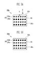
- FIG. 3A is a perspective view of the barrier according to the present invention
- FIG. 3B is an exploded perspective view of the barrier of FIG. 3A
- FIG. 3C is a cross-sectional view taken along a line A-A of FIG. 3A
- FIG. 3D is an exploded cross-sectional view of FIG. 3C .
- the barrier 150a disposed between the plurality of battery cells 10 may include the plate 151 having at least one opening 151a, and the protrusion 152 formed to pass through the opening 151a.
- the protrusion 152 includes an elastomer.
- the barrier 150a is disposed between two neighboring battery cells 10 to space the battery cells 10 from each other. Thus, a space may be formed between the battery cells 10 due to the barrier 150a.
- the space may function as a path to discharge heat through so that heat generated in the battery cells 10 due to a plurality of times of charging and discharging is not accumulated. Further, the space may be a path of a heat transmission medium for cooling or heating of the battery cells 10.
- the openings 151a may be formed at regular intervals, and a plurality of openings 151a may be formed.
- the plate 151 may include a first side 151b and a second side 151c.
- the protrusion 152 may include a first head 152a or a second head 152b formed on the first side 151b or the second side 151c. Further, the protrusion 152 may further include a connecting member 152c connecting the first head 152a and the second head 152b and formed to pass through the opening 151a.
- the first head 152a or the second head 152b may have a round or polygonal tube shape, and the first heads 152a or the second heads 152 may be formed on the plate 151 at regular intervals.
- the battery cells 10 use a structure of pressing the battery cells 10 at a predetermined pressure or more in order to control swelling of the battery cells 10 occurring in charging and discharging processes. Further, neighboring battery cells 10 are spaced so that the battery cells 10 are heated or heat is discharged from the battery cells 10. Thus, the barrier 150a having an approximately corresponding size to the battery cells 10 is disposed between the battery cells 10.
- the barrier 150a may include the protrusion 152 and the plate 151 to support the protrusion 152. Further, the barrier 150a may be disposed so that the protrusion 152 is in direct contact with the battery cells 10.
- an insulating process is applied to at least one of the battery cells 10 and the protrusion 152 to prevent a short circuit from occurring therebetween.
- the insulating process is achieved by performing tubing on a surface of the battery cells 10 using a nonconductive material of an insulating film.
- the tubing formed on the external surface of the battery cells 10 may be broken by external impact or may be damaged by friction between the protrusion 152 and the battery cell 10 due to vibrations in the battery module 100.
- the tubing is damaged, the battery cells 10 may electrically short-circuit with the outside, and an external appearance of the battery cells 10 may become deformed.
- the barrier 150a includes the protrusion 152, a part being in direct contact with the battery cells 10, at least part of which may be formed an elastomer.
- the elastomer is a material which may be restored from deformation by external force and has excellent anti-attrition, elongation, and impact strength.
- At least one of the first head 152a, the second head 152, and the connecting member 152c which constitute the protrusion 152 may be formed of an elastomer. Further, the first head 152a and the connecting member 152c may be formed of an elastomer, and may be integrated or be formed separately.
- the connecting member 152c passes through the opening 151a so that the first head 152a is disposed on the first side 151b of the plate 151, and then the second head 152b is coupled with the passing through connecting member 152c on the second side 151c of the plate 151, thus manufacturing the barrier 150a according to the present embodiment.
- the connecting member 152c may have a corresponding shape to the opening 151a of the plate 151.
- the connecting member 152c is provided to connect and fix the first head 152a and the second head 152b disposed on the first side 151b and the second side 151c of the barrier 150a, passing through the opening 151a of the plate 151.
- the connecting member 152c may have a size enough to pass through the opening 151a, but may preferably have a corresponding size to the opening 151a in order to stably fix the first head 152a and the second head 152b and to improve anti-vibration in the battery module 100.
- an end portion of the connecting member 152c which is not connected to the first head 152a and a portion of the second head 152b corresponding to the end portion of the connecting member 152c may each further include a coupling part.
- the coupling parts are provided to couple and fix the connecting member 152c and the second head 152b, and the coupling part provided on the end portion of the connecting member 152c may be correspondingly coupled with the coupling part provided on the second head 152b.
- the coupling parts may include a groove-protrusion combination, a hook combination, a screw combination, or the like.
- the elastomer forming the at least part of the protrusion 152 may have a hardness of 30 Hs to 100 Hs and may include, for example, at least one of rubber, silicon, and polystyrene.
- the hardness of the elastomer is less than 30 Hs, the elastomer has inferior durability, so that the elastomer part of the protrusion 152 may be easily worn out or damaged.
- the protrusion 152 has an inflexible structure, so that anti-vibration is not sufficiently effective. Thus, the tubing of the battery cells 10 is damaged by external force or vibrations to cause a short circuit.
- FIGS. 4A to 9C Another exemplary embodiment of the present invention is described with reference to FIGS. 4A to 9C . Except for the following description, descriptions with reference to FIGS. 4A to 9C are similar to those described above with reference to FIGS. 1 to 3D , and thus are not repeated.
- FIG. 4A is a perspective view of a barrier according to the other embodiment of the present invention
- FIG. 4B is a cross-sectional view taken along a line A'-A' of FIG. 4A .
- a barrier 150b may include a plate 151 having at least one opening 151a and a protrusion 152 formed to pass through the opening 151a.
- at least part of the protrusion 152 is formed of an elastomer.
- the protrusion 152 may include a first head 252a formed on a first side 151b or a second side 151c of the plate 151. Further, the protrusion 152 may further include a connecting member 152c passing through the opening 151a and being integrated with the first head 152a.
- the first head 152a is formed on the first side 151b of the plate 151, but a second head is omitted.
- One end portion of the connecting member 152c of the protrusion 152 is exposed on the second side 151c.
- battery cells facing the second side 151c are spaced by the exposed end portion of the connecting member 152c, so that a space between the battery cells is formed.
- the connecting member 152c may be integrated with the first head 152a, and a process of forming the second head may be omitted, and thus the protrusion 152 may be formed via a single process, improving processing efficiency.
- the connecting member 152c may be fixed by friction between the connecting member 152c and the opening 151a of the plate 151 without the second head.
- FIG. 5A is a perspective view of one side of a barrier according to still another exemplary embodiment of the present invention
- FIG. 5B is a perspective view of another side of the barrier of FIG. 5A
- FIG. 5C is a cross-sectional view taken along a line B-B of FIG. 5C
- FIG. 5D is an exploded cross-sectional view of FIG. 5C .
- a barrier 250a may include a plate 251 having at least one opening 251a and a protrusion 252 formed to pass through the opening 251a.
- at least part of the protrusion 252 is formed of an elastomer.
- the plate 251 includes a first side 251b and a second side 251c
- the protrusion 252 may include a first head 252a or a second head 252b formed on the first side 251b or the second side 251c.
- the protrusion 252 may further include a connecting member 252c connecting the first head 252a and the second head 252b and integrated with the first head 252a.
- a plurality of rows of the first heads 252a or a plurality of rows of the second heads 252b may be arranged in lines on the first side 251b or the second side 251c of the plate 251, but the rows of the first heads 252a and the rows of the second heads 252b may be alternately arranged on the same side.
- the first head 252a and the second head 252b may be formed of different materials.
- the first head 252a and the second head 252b may be formed of elastomers, which are different types, or at least one of the first head 252a and the second head 252b may be formed an elastomer.
- the connecting member 252c may also be formed of a different material from the first head 252a or the second head 252b.
- the connecting member 252c is integrated with the first head 252a to include the same material as the first head 252a.
- the first head 252a integrated with the connecting member 252c may be formed on the first side 251b or the second side 251c of the plate 251 to pass through the opening 251a.
- the connecting member 252c passing through the opening 251a may be coupled with the second head 252b on the second side 251c or the first side 251b.
- the first heads 252a may be formed on both the first side 251b and the second side 251c, and a row of the first heads 252a arranged in a line and a row of the second heads 252b arranged in a line may be alternately disposed on the first side 251b.
- the coupling may be performed by a groove-protrusion combination, a hook combination, a screw combination, or the like.
- materials or arrangements of the first heads 252a and the second heads 252b may be properly modified based on a design of the battery module, for example, a channel of a refrigerant, anti-vibration of the battery cells, or the like.
- FIG. 6A is a perspective view of a barrier according to yet another exemplary embodiment of the present invention
- FIG. 6B is a cross-sectional view taken along a line B'-B' of FIG. 6A .
- a barrier 250b may include a plate 251 having at least one opening 251a and a protrusion 252 formed to pass through the opening 251a.
- at least part of the protrusion 252 is formed of an elastomer.
- the plate 251 may include a first side 251b and a second side 251c, and the protrusion 252 may include a first head 252a and a connecting member 252c.
- a plurality of rows of first heads 252a may be arranged in lines on the first side 251b or the second side 251c of the plate 251, but the first heads 252a may be omitted in even-number rows on one side and odd-number rows on the other side.
- the protrusions 252 may be provided only in odd-number rows on the first side 251b and be provided only in even-number rows on the second side 251c, and thus end portions of the first heads 252a and end portions of the connecting member 252c are alternately arranged in different rows on the first side 251b or the second side 251c.
- FIG. 7A is a perspective view of a barrier according to still another exemplary embodiment of the present invention
- FIG. 7B is a cross-sectional view taken along a line C-C of FIG. 7A .
- a barrier 350 may include a first side 351b, a second side 351c, and at least one opening 351a formed to extend from the first side 351b and the second side 351c.
- the barrier 350 may include a protrusion 352 formed to pass through the opening 351a.
- at least part of the protrusion 352 is formed of an elastomer.
- the protrusion 352 may include a first head 352a and a second head 352b formed on the first side 351b and the second side 351c of the plate 351, and a connecting member 352c connecting the first head 352a to the second head 352b. Further, the connecting member 352c may include a spring.
- the connecting member 352 is formed to pass through the opening 351a of the plate 351 and connects the first head 352a to the second head 352b to fix the first head 352a and the second head 352b on the plate 351.
- the connecting member 352c includes a spring to be used regardless of a change in a thickness of the plate 351. That is, the connecting member 352c includes a spring having superior elasticity to be free from limitations in a size of the barrier 350, reducing a defect due to an assembly tolerance.
- FIG. 8A is a perspective view of a barrier according to yet another exemplary embodiment of the present invention
- FIG. 8B is a cross-sectional view taken along a line D-D of FIG. 8A
- FIG. 8C is an exploded cross-sectional view of FIG. 8B .
- a barrier 450 may include a first side 451b, a second side 451c, and at least one opening 451a formed to extend from the first side 451b and the second side 451c.
- the barrier 450 may include a protrusion 452 formed to pass through the opening 451a.
- at least part of the protrusion 452 is formed of an elastomer.
- the protrusion 452 may include a pair of a first head 452a and a second head 452b, and a connecting member 452c connecting the first head 452a to the second head 452b.
- the first head 452a, the second head 452b, and the connecting member 452c may be integrated.
- the protrusion 452 may include an elastomer, and thus an external appearance thereof may not be fixed but be easily transformed by external force.
- the protrusion 452 in which the first head 452a, the second head 452b, and the connecting member 452c are integrated passes through the opening 451a on the first side 451b or the second side 451c of the plate 451.
- first head 451b or the second side 451c has a tapering-shape cross section to easily pass through the opening 451a. That is, one end portion of the first head 452a or the second head 452b which is not connected to the connecting member 452c has a smaller diameter than or approximately the same diameter as the opening 451 to easily pass. Further, another end portion of the first head 452a or the second head 452b which is connected to the connecting member 452c has a larger diameter than the opening 451a to be fixed to the opening 451a, not to be separated after passing through the opening 451a.
- the other end portion of the first head 452a or the second head 452b which is formed to be larger than the opening 451a is stuck on an entrance of the opening 451a, so that the protrusion 452 may be stably fixed with the plate 451.
- FIG. 9A is a perspective view of a barrier according to still another exemplary embodiment of the present invention
- FIG. 9B is a cross-sectional view taken along a line E-E of FIG. 9A
- FIG. 9C is an exploded perspective view of FIG. 9B .
- a barrier 550 may include a plate 551 having at least one opening 551a and formed of a first side 551b and a second side 551c, and a protrusion 552 formed to pass through the opening 551a.
- the protrusion 552 is formed of an elastomer.
- the protrusion 552 may include a first head 552a and a connecting member 552c connected to the first head 552a.
- the connecting member 552c may be integrated with the first head 552a or be formed separately.
- the connecting member 552c may be formed to have an approximate half or less of a length of the opening 551a. That is, protrusions 552 formed of the first head 552a and the connecting member 552c are provided both on the first side 551b and the second side 551c of the plate 551, and connecting members 552c provided to pass through the opening 551a on the first side 551b and the second side 551c face each other in the opening 551a.
- the same protrusions 522 may be used to decrease manufacturing costs of the battery module, reducing production costs.
Landscapes
- Chemical & Material Sciences (AREA)
- Chemical Kinetics & Catalysis (AREA)
- Electrochemistry (AREA)
- General Chemical & Material Sciences (AREA)
- Engineering & Computer Science (AREA)
- Manufacturing & Machinery (AREA)
- Battery Mounting, Suspending (AREA)
Abstract
Description
- The embodiment relates to a battery module, and more particularly, to a module including a plurality of battery cells and a barrier disposed between the battery cells.
- Recently, a high-output battery module using a high energy density nonaqueous electrolyte is being developed, and the high-output battery module is realized by a high-capacity battery module formed by connecting a plurality of battery cells in series so that the battery module is used for devices using high power, for example, a driving motor of an electric car.
- A battery cell includes an electrode assembly formed of a positive plate and a negative plate, and an electrolyte and generates energy through an electrochemical reaction between the plates and the electrolyte. Here, gas may be generated in the battery cell due to a side reaction of the electrochemical reaction.
- The gas may deform an external appearance of the battery cell to affect a shape of the battery module constituted by a plurality of arranged battery cells, interrupting securely fixing the battery cell.
- An aspect of the present invention is to provide a battery module which becomes light by using a novel barrier.
- Another aspect of the present invention is to provide a battery module having a barrier being adapted to effectively control swelling of a battery cell.
- According to an aspect of the present invention, there is provided a battery module comprising: a plurality of battery cells, at least one barrier arranged between the adjacent battery cells of the plurality of battery cells; wherein the at least one barrier comprises a plate and a protrusion extending from the plate, wherein at least a part of the protrusion comprises an elastic member.
- In the sense of the present invention, the protrusion is (at least) partly protruding from the plate. In case the protrusion is formed in a hole which is formed in the plate, the protrusion only partly protrudes from the plate. That is, the portion being located within the hole, does not protrude from the plate while the portion being located outside of the hole, does protrude from the plate. In other words, the protrusions of the present invention are spacers formed each of the adjacent battery cells such to space the adjacent battery cells apart from each other.
- Preferably the elastic member comprises an elastomer. Preferably the elastic member consist of an elastomer. Preferably the plate includes at least one opening and at least a part of the protrusion is formed to pass through the opening. Preferably a barrier is formed between each pair of adjacent battery cells of the plurality of battery cells. Preferably the plate of the barrier comprises a plurality of openings being formed in a regular pattern. Preferably the plate of the barrier comprises a plurality of openings being formed in a pattern of equidistant holes being formed along rows and columns.
- Preferably the protrusion of the at least one barrier directly contacts each of the adjacent battery cells. Preferably the protrusion of the at least one barrier comprises a first head formed on a first side of the plate and/or a second head formed on a second side of the plate. Preferably the protrusion of the at least one barrier further comprises a connecting member being connected to at least one of the first head and the second head and formed to pass through the opening. Preferably at least one of the first head, the second head and the connecting member is formed of an elastomer. Preferably the connecting member comprises a spring. Preferably the material of the first head is different to the material of the second head. Preferably an end portion of the connecting member and a portion of one selected from the first head and the second head which faces toward the end portion of the connecting member comprise a coupling part.
- Preferably the elastomer of the protrusion has a hardness of 30 Hs to 200 Hs according to the Korean Standard KS B 0807 ("METHOD OF SHORE HARDNESS TEST"). More preferably the elastomer of the protrusion has a hardness of 30 Hs to 100 Hs. More preferably the elastomer of the protrusion has a hardness of 40 Hs to 90 Hs. Still more preferably the elastomer of the protrusion has a hardness of 50 Hs to 80 Hs.
- Preferably the elastomer of the protrusion comprises at least one material selected from the group consisting of rubber, silicon, and polystyrene. Preferably the at least one barrier has a size corresponding to the size of the plurality of battery cells. That is, a ratio of the size of the at least one barrier and the size of a battery cell preferably ranges between 0.85 and 1.15, more preferably between 0.95 and 1.05. Preferably all batteries of the plurality of battery cells have the same size. More preferably the at least one barrier has a size equal to the size of the plurality of battery cells.
- Preferably a cross-section of the connecting member has a shape corresponding to the shape of the opening of the plate. That is, a ratio of the surface area of the cross-section of the connecting member and the surface area of the cross-section of the opening of the plate preferably ranges between 0.85 and 1.00, more preferably between 0.95 and 1.00. Preferably the cross-sections of all openings have the same size. Preferably the cross-sections of all connecting member have the same size. More preferably cross-section of the connecting member has a shape equal to the shape of the opening of the plate.
- Preferably the first head and/or the second head have a round shape or a polygonal tube shape. Preferably the first head and/or the second head comprise a tapering-shape cross section, wherein the sectional axis extends along the longitudinal axis of the connecting member.
- According to another aspect of the present invention, there is provided a vehicle comprising a battery module according to at least one of the above disclosed features.
- According to another aspect of the present invention, there is provided a battery module including a plurality of battery cells arranged in one direction, a barrier disposed between the plurality of battery cells; and a housing accommodating the battery cells and the barrier, wherein the barrier includes a plate including at least one opening and a protrusion formed to pass through the opening, and at least part of the protrusion is formed of an elastomer.
- The opening may include a plurality of holes formed in the plate at regular intervals.
- The plate may include a first side and a second side, and the protrusion may include a first head or a second head formed in the first side or the second side. Here, the protrusion may further include a connecting member connecting the first head to the second head and being formed to pass through the opening of the plate.
- Further, the first head or the second head may have a round or polygonal tube shape.
- Here, the first heads or the second heads may be formed at regular intervals.
- One of the first head, the second head, and the connecting member may be formed of an elastomer.
- Further, the first head and the connecting member may be formed of an elastomer and be integrated.
- A plurality of rows of the first heads or a plurality of rows of the second heads may be arranged in lines on the first side or the second side of the plate, but the rows of the first heads and the rows of the second heads may be alternately arranged on the same side.
- The first head and the second head may be connected by the connecting member and be integrated.
- The connecting member may be formed to have a corresponding size to the opening of the plate.
- The connecting member may include a spring.
- The elastomer may include one of rubber, silicon, and polystyrene.
- The elastomer may have a hardness of 30 Hs to 200 Hs.
- The housing may include a pair of first and second end plates disposed outside the battery cells, and a side plate and a bottom plate connecting the first and second end plates.
- As described above, according to exemplary embodiments of the present invention, a battery module uses a novel barrier, so that the battery module effectively cools battery cells and becomes light.
- Further, according to exemplary embodiments of the present invention, the battery module effectively prevents swelling of battery cells to improve reliability of the battery cells and to enhance production efficiency.
- The accompanying drawings, together with the specification, illustrate exemplary embodiments of the present invention, and, together with the description, serve to explain the principles of the present invention.
-
FIG. 1 is a perspective view of a battery module according to an exemplary embodiment of the present invention; -
FIG. 2 is an exploded perspective view of the battery module ofFIG. 1 ; -
FIG. 3A is a perspective view of a barrier according to an exemplary embodiment of the present invention; -
FIG. 3B is an exploded perspective view of the barrier ofFIG. 3A ; -
FIG. 3C is a cross-sectional view taken along a line A-A ofFIG. 3A ; -
FIG. 3D is an exploded cross-sectional ofFIG. 3C ; -
FIG. 4A is a perspective of a barrier according to another exemplary example of the present invention; -
FIG. 4B is a cross-sectional view taken along a line A'-A' ofFIG. 4A ; -
FIG. 5A is a perspective view of one side of a barrier according to still another exemplary embodiment of the present invention; -
FIG. 5B is a perspective view of another side of the barrier ofFIG. 5A ; -
FIG. 5C is a cross-sectional view taken along a line B-B ofFIG. 5A ; -
FIG. 5D is an exploded cross-sectional view ofFIG. 5C ; -
FIG. 6A is a perspective of a barrier according to yet another exemplary example of the present invention; -
FIG. 6B is a cross-sectional view taken along a line B'-B' ofFIG. 6A ; -
FIG. 7A is a perspective of a barrier according to still another exemplary example of the present invention; -
FIG. 7B is a cross-sectional view taken along a line C-C ofFIG. 7A ; -
FIG. 8A is a perspective of a barrier according to yet another exemplary example of the present invention; -
FIG. 8B is a cross-sectional view taken along a line D-D ofFIG. 8A ; -
FIG. 8C is an exploded cross-sectional view ofFIG. 8B . -
FIG. 9A is a perspective of a barrier according to still another exemplary example of the present invention; -
FIG. 9B is a cross-sectional view taken along a line E-E ofFIG. 9A ; and -
FIG. 9C is an exploded cross-sectional view ofFIG. 9B . - In the following detailed description, only certain exemplary embodiments of the present invention have been shown and described, simply by way of illustration. As those skilled in the art would realize, the described embodiments may be modified in various different ways, all without departing from the scope of the present invention. Accordingly, the drawings and description are to be regarded as illustrative in nature and not restrictive. In addition, when an element is referred to as being "on" another element, it can be directly on the other element or be indirectly on the other element with one or more intervening elements interposed therebetween. Also, when an element is referred to as being "connected to" another element, it can be directly connected to the other element or be indirectly connected to the other element with one or more intervening elements interposed therebetween. Hereinafter, like reference numerals refer to like elements.
- Referring to
FIGS. 1 to 3D , an exemplary embodiment of the present invention is described. -
FIG. 1 is a perspective view of a battery module according to the exemplary embodiment of the present invention, andFIG. 2 is an exploded perspective view ofFIG. 1 . - Referring to
FIGS. 1 and2 , thebattery module 100 according to the present embodiment includes a plurality ofbattery cells 10 arranged in one direction; abarrier 150a disposed between the plurality ofbattery cells 10; and ahousing battery cells 10 and thebarrier 150a. Thebarrier 150a includes aplate 151 having at least one opening, and aprotrusion 152 formed to pass through the opening, wherein at least part of theprotrusion 152 includes an elastomer. - The
battery cells 10 may be formed by accommodating an electrode assembly and an electrolyte in a battery case and sealing the battery case with acap assembly 14. Thecap assembly 14 may include apositive terminal 11 and anegative terminal 12 which are formed on opposite end portions of thecap assembly 14 and avent 13 formed between theterminals positive terminal 11, and the negative plate is connected to thenegative terminal 12, so that energy generated by an electrochemical reaction of the electrode assembly and the electrolyte is transmitted to the outside. Further, thevent 13 functions as a path through which gas generated in thebattery cell 10 is discharged to the outside. - The
housing battery cells 10 and thebarrier 150a to form thebattery module 100. Thehousing second end plates battery cells 10, and aside plate 130 and abottom plate 140 which connect the end plates. - The first and
second end plates side plates 130, and thebottom plate 140 form a space to accommodate thebattery cells 10, and thebattery cells 10 are arranged in one direction in the formed space. Here, thebattery cells 10 are arranged side by side with wider front sides facing each other. Thepositive terminal 11 or thenegative terminal 12 of two neighboringbattery cells 10 may be electrically connected through a bus bar 25. Thebus bar 15 includes a hole through which thepositive terminal 11 and thenegative terminal 12 pass, and thebus bar 15 with thepositive terminal 11 and thenegative terminal 12 passing through the hole to be connected may be fixed by anut 16 or the like. - The pair of
side plates 130 supports opposite lateral sides of thebattery cells 10, and thebottom plate 140 supports a bottom side of thebattery cells 10. One end portions of theside plates 130 and the bottom plate are respectively coupled with thefirst end plate 110, and another end portions thereof are coupled with thesecond end plate 120, so that the first andsecond end plates - The first and
second end plates battery cells 10 disposed at opposite ends to press the plurality ofbattery cells 10 inwards. Here, thebattery cells 10 supported by the first andsecond end plates positive terminals 11 and thenegative terminals 12 being alternately disposed, so that neighboring terminals are connected in series. - The
housing second end plates side plates 130, and thebottom plate 140 is provided to stably fix thebattery cells 10 and may be modified variously, not limited to a configuration in the present embodiment. Further, a connected structure and a number ofbattery cells 10 may be changed based on a design of thebattery module 100. -
FIG. 3A is a perspective view of the barrier according to the present invention,FIG. 3B is an exploded perspective view of the barrier ofFIG. 3A ,FIG. 3C is a cross-sectional view taken along a line A-A ofFIG. 3A , andFIG. 3D is an exploded cross-sectional view ofFIG. 3C . - Referring to
FIGS. 3A to 3D , thebarrier 150a disposed between the plurality ofbattery cells 10 may include theplate 151 having at least oneopening 151a, and theprotrusion 152 formed to pass through theopening 151a. Here, at least part of theprotrusion 152 includes an elastomer. - The
barrier 150a is disposed between two neighboringbattery cells 10 to space thebattery cells 10 from each other. Thus, a space may be formed between thebattery cells 10 due to thebarrier 150a. The space may function as a path to discharge heat through so that heat generated in thebattery cells 10 due to a plurality of times of charging and discharging is not accumulated. Further, the space may be a path of a heat transmission medium for cooling or heating of thebattery cells 10. - The
openings 151a may be formed at regular intervals, and a plurality ofopenings 151a may be formed. Theplate 151 may include afirst side 151b and asecond side 151c. Theprotrusion 152 may include afirst head 152a or asecond head 152b formed on thefirst side 151b or thesecond side 151c. Further, theprotrusion 152 may further include a connectingmember 152c connecting thefirst head 152a and thesecond head 152b and formed to pass through theopening 151a. - The
first head 152a or thesecond head 152b may have a round or polygonal tube shape, and thefirst heads 152a or thesecond heads 152 may be formed on theplate 151 at regular intervals. - Generally, the
battery cells 10 use a structure of pressing thebattery cells 10 at a predetermined pressure or more in order to control swelling of thebattery cells 10 occurring in charging and discharging processes. Further, neighboringbattery cells 10 are spaced so that thebattery cells 10 are heated or heat is discharged from thebattery cells 10. Thus, thebarrier 150a having an approximately corresponding size to thebattery cells 10 is disposed between thebattery cells 10. Here, thebarrier 150a may include theprotrusion 152 and theplate 151 to support theprotrusion 152. Further, thebarrier 150a may be disposed so that theprotrusion 152 is in direct contact with thebattery cells 10. - When the
battery module 100 is formed, an insulating process is applied to at least one of thebattery cells 10 and theprotrusion 152 to prevent a short circuit from occurring therebetween. Generally, the insulating process is achieved by performing tubing on a surface of thebattery cells 10 using a nonconductive material of an insulating film. However, the tubing formed on the external surface of thebattery cells 10 may be broken by external impact or may be damaged by friction between theprotrusion 152 and thebattery cell 10 due to vibrations in thebattery module 100. When the tubing is damaged, thebattery cells 10 may electrically short-circuit with the outside, and an external appearance of thebattery cells 10 may become deformed. - The
barrier 150a includes theprotrusion 152, a part being in direct contact with thebattery cells 10, at least part of which may be formed an elastomer. Generally, the elastomer is a material which may be restored from deformation by external force and has excellent anti-attrition, elongation, and impact strength. - At least one of the
first head 152a, thesecond head 152, and the connectingmember 152c which constitute theprotrusion 152 may be formed of an elastomer. Further, thefirst head 152a and the connectingmember 152c may be formed of an elastomer, and may be integrated or be formed separately. - When the
first head 152a and the connectingmember 152c are integrated, the connectingmember 152c passes through theopening 151a so that thefirst head 152a is disposed on thefirst side 151b of theplate 151, and then thesecond head 152b is coupled with the passing through connectingmember 152c on thesecond side 151c of theplate 151, thus manufacturing thebarrier 150a according to the present embodiment. - Here, the connecting
member 152c may have a corresponding shape to theopening 151a of theplate 151. The connectingmember 152c is provided to connect and fix thefirst head 152a and thesecond head 152b disposed on thefirst side 151b and thesecond side 151c of thebarrier 150a, passing through theopening 151a of theplate 151. Thus, the connectingmember 152c may have a size enough to pass through theopening 151a, but may preferably have a corresponding size to theopening 151a in order to stably fix thefirst head 152a and thesecond head 152b and to improve anti-vibration in thebattery module 100. - Further, an end portion of the connecting
member 152c which is not connected to thefirst head 152a and a portion of thesecond head 152b corresponding to the end portion of the connectingmember 152c may each further include a coupling part. The coupling parts are provided to couple and fix the connectingmember 152c and thesecond head 152b, and the coupling part provided on the end portion of the connectingmember 152c may be correspondingly coupled with the coupling part provided on thesecond head 152b. For example, the coupling parts may include a groove-protrusion combination, a hook combination, a screw combination, or the like. - The elastomer forming the at least part of the
protrusion 152 may have a hardness of 30 Hs to 100 Hs and may include, for example, at least one of rubber, silicon, and polystyrene. When the hardness of the elastomer is less than 30 Hs, the elastomer has inferior durability, so that the elastomer part of theprotrusion 152 may be easily worn out or damaged. When the hardness of the elastomer is more than 100 Hs, theprotrusion 152 has an inflexible structure, so that anti-vibration is not sufficiently effective. Thus, the tubing of thebattery cells 10 is damaged by external force or vibrations to cause a short circuit. - Hereinafter, another exemplary embodiment of the present invention is described with reference to
FIGS. 4A to 9C . Except for the following description, descriptions with reference toFIGS. 4A to 9C are similar to those described above with reference toFIGS. 1 to 3D , and thus are not repeated. -
FIG. 4A is a perspective view of a barrier according to the other embodiment of the present invention, andFIG. 4B is a cross-sectional view taken along a line A'-A' ofFIG. 4A . - Referring to
FIGS. 4A and 4B , abarrier 150b may include aplate 151 having at least oneopening 151a and aprotrusion 152 formed to pass through theopening 151a. Here, at least part of theprotrusion 152 is formed of an elastomer. Theprotrusion 152 may include afirst head 252a formed on afirst side 151b or asecond side 151c of theplate 151. Further, theprotrusion 152 may further include a connectingmember 152c passing through theopening 151a and being integrated with thefirst head 152a. - In the present embodiment, only the
first head 152a is formed on thefirst side 151b of theplate 151, but a second head is omitted. One end portion of the connectingmember 152c of theprotrusion 152 is exposed on thesecond side 151c. Thus, battery cells facing thesecond side 151c are spaced by the exposed end portion of the connectingmember 152c, so that a space between the battery cells is formed. The connectingmember 152c may be integrated with thefirst head 152a, and a process of forming the second head may be omitted, and thus theprotrusion 152 may be formed via a single process, improving processing efficiency. Here, the connectingmember 152c may be fixed by friction between the connectingmember 152c and theopening 151a of theplate 151 without the second head. -
FIG. 5A is a perspective view of one side of a barrier according to still another exemplary embodiment of the present invention,FIG. 5B is a perspective view of another side of the barrier ofFIG. 5A ,FIG. 5C is a cross-sectional view taken along a line B-B ofFIG. 5C, and FIG. 5D is an exploded cross-sectional view ofFIG. 5C . - Referring to
FIGS. 5A to 5D , abarrier 250a may include aplate 251 having at least oneopening 251a and aprotrusion 252 formed to pass through theopening 251a. Here, at least part of theprotrusion 252 is formed of an elastomer. - The
plate 251 includes afirst side 251b and asecond side 251c, and theprotrusion 252 may include afirst head 252a or asecond head 252b formed on thefirst side 251b or thesecond side 251c. Further, theprotrusion 252 may further include a connectingmember 252c connecting thefirst head 252a and thesecond head 252b and integrated with thefirst head 252a. A plurality of rows of thefirst heads 252a or a plurality of rows of thesecond heads 252b may be arranged in lines on thefirst side 251b or thesecond side 251c of theplate 251, but the rows of thefirst heads 252a and the rows of thesecond heads 252b may be alternately arranged on the same side. - In the present embodiment, the
first head 252a and thesecond head 252b may be formed of different materials. For example, thefirst head 252a and thesecond head 252b may be formed of elastomers, which are different types, or at least one of thefirst head 252a and thesecond head 252b may be formed an elastomer. The connectingmember 252c may also be formed of a different material from thefirst head 252a or thesecond head 252b. However, in the present embodiment, the connectingmember 252c is integrated with thefirst head 252a to include the same material as thefirst head 252a. - The
first head 252a integrated with the connectingmember 252c may be formed on thefirst side 251b or thesecond side 251c of theplate 251 to pass through theopening 251a. The connectingmember 252c passing through theopening 251a may be coupled with thesecond head 252b on thesecond side 251c or thefirst side 251b. Thefirst heads 252a may be formed on both thefirst side 251b and thesecond side 251c, and a row of thefirst heads 252a arranged in a line and a row of thesecond heads 252b arranged in a line may be alternately disposed on thefirst side 251b. - The coupling may be performed by a groove-protrusion combination, a hook combination, a screw combination, or the like. Here, materials or arrangements of the
first heads 252a and thesecond heads 252b may be properly modified based on a design of the battery module, for example, a channel of a refrigerant, anti-vibration of the battery cells, or the like. -
FIG. 6A is a perspective view of a barrier according to yet another exemplary embodiment of the present invention, andFIG. 6B is a cross-sectional view taken along a line B'-B' ofFIG. 6A . - Referring to
FIGS. 6A and 6B , abarrier 250b may include aplate 251 having at least oneopening 251a and aprotrusion 252 formed to pass through theopening 251a. Here, at least part of theprotrusion 252 is formed of an elastomer. - The
plate 251 may include afirst side 251b and asecond side 251c, and theprotrusion 252 may include afirst head 252a and a connectingmember 252c. A plurality of rows offirst heads 252a may be arranged in lines on thefirst side 251b or thesecond side 251c of theplate 251, but thefirst heads 252a may be omitted in even-number rows on one side and odd-number rows on the other side. That is, theprotrusions 252 may be provided only in odd-number rows on thefirst side 251b and be provided only in even-number rows on thesecond side 251c, and thus end portions of thefirst heads 252a and end portions of the connectingmember 252c are alternately arranged in different rows on thefirst side 251b or thesecond side 251c. -
FIG. 7A is a perspective view of a barrier according to still another exemplary embodiment of the present invention, andFIG. 7B is a cross-sectional view taken along a line C-C ofFIG. 7A . - Referring to
FIGS. 7A and 7B , abarrier 350 may include afirst side 351b, asecond side 351c, and at least oneopening 351a formed to extend from thefirst side 351b and thesecond side 351c. Here, thebarrier 350 may include aprotrusion 352 formed to pass through theopening 351a. Here, at least part of theprotrusion 352 is formed of an elastomer. - The
protrusion 352 may include afirst head 352a and asecond head 352b formed on thefirst side 351b and thesecond side 351c of theplate 351, and a connectingmember 352c connecting thefirst head 352a to thesecond head 352b. Further, the connectingmember 352c may include a spring. - The connecting
member 352 is formed to pass through theopening 351a of theplate 351 and connects thefirst head 352a to thesecond head 352b to fix thefirst head 352a and thesecond head 352b on theplate 351. Here, the connectingmember 352c includes a spring to be used regardless of a change in a thickness of theplate 351. That is, the connectingmember 352c includes a spring having superior elasticity to be free from limitations in a size of thebarrier 350, reducing a defect due to an assembly tolerance. -
FIG. 8A is a perspective view of a barrier according to yet another exemplary embodiment of the present invention,FIG. 8B is a cross-sectional view taken along a line D-D ofFIG. 8A, and FIG. 8C is an exploded cross-sectional view ofFIG. 8B . - Referring to
FIGS. 8A to 8C , abarrier 450 may include afirst side 451b, asecond side 451c, and at least oneopening 451a formed to extend from thefirst side 451b and thesecond side 451c. Here, thebarrier 450 may include aprotrusion 452 formed to pass through theopening 451a. Here, at least part of theprotrusion 452 is formed of an elastomer. - The
protrusion 452 may include a pair of afirst head 452a and a second head 452b, and a connectingmember 452c connecting thefirst head 452a to the second head 452b. Here, thefirst head 452a, the second head 452b, and the connectingmember 452c may be integrated. - In the present embodiment, the
protrusion 452 may include an elastomer, and thus an external appearance thereof may not be fixed but be easily transformed by external force. Thus, theprotrusion 452 in which thefirst head 452a, the second head 452b, and the connectingmember 452c are integrated passes through theopening 451a on thefirst side 451b or thesecond side 451c of theplate 451. - Further, the
first head 451b or thesecond side 451c has a tapering-shape cross section to easily pass through theopening 451a. That is, one end portion of thefirst head 452a or the second head 452b which is not connected to the connectingmember 452c has a smaller diameter than or approximately the same diameter as theopening 451 to easily pass. Further, another end portion of thefirst head 452a or the second head 452b which is connected to the connectingmember 452c has a larger diameter than theopening 451a to be fixed to theopening 451a, not to be separated after passing through theopening 451a. That is, the other end portion of thefirst head 452a or the second head 452b which is formed to be larger than theopening 451a is stuck on an entrance of theopening 451a, so that theprotrusion 452 may be stably fixed with theplate 451. -
FIG. 9A is a perspective view of a barrier according to still another exemplary embodiment of the present invention,FIG. 9B is a cross-sectional view taken along a line E-E ofFIG. 9A, and FIG. 9C is an exploded perspective view ofFIG. 9B . - Referring to
FIGS. 9A to 9C , abarrier 550 may include aplate 551 having at least oneopening 551a and formed of afirst side 551b and asecond side 551c, and aprotrusion 552 formed to pass through theopening 551a. Here, at least part of theprotrusion 552 is formed of an elastomer. - In the present embodiment, the
protrusion 552 may include afirst head 552a and a connectingmember 552c connected to thefirst head 552a. The connectingmember 552c may be integrated with thefirst head 552a or be formed separately. - The connecting
member 552c may be formed to have an approximate half or less of a length of theopening 551a. That is,protrusions 552 formed of thefirst head 552a and the connectingmember 552c are provided both on thefirst side 551b and thesecond side 551c of theplate 551, and connectingmembers 552c provided to pass through theopening 551a on thefirst side 551b and thesecond side 551c face each other in theopening 551a. Thus, the same protrusions 522 may be used to decrease manufacturing costs of the battery module, reducing production costs. - While the present invention has been described in connection with certain exemplary embodiments, it is to be understood that the invention is not limited to the disclosed embodiments, but, on the contrary, is intended to cover various modifications and equivalent arrangements included within the scope of the appended claims, and-equivalents thereof.
Claims (15)
- A battery module (100) comprising:a plurality of battery cells (10),at least one barrier (150a, 150b, 250a, 250b, 350, 450, 550) arranged between adjacent battery cells (10) of the plurality of battery cells (10);characterized in thatthe at least one barrier (150a, 150b, 250a, 250b, 350, 450, 550) comprises a plate (151, 251, 351, 451, 551) and a protrusion (152, 252, 352, 452, 552) extending from the plate (151, 251, 351, 451, 551), wherein at least a part of the protrusion (152, 252, 352, 452, 552) comprises an elastic member.
- The battery module (100) of claim 1, wherein the elastic member comprises an elastomer.
- The battery module (100) according to any one of the preceding claims, wherein the plate (151, 251, 351, 451, 551) includes at least one opening (151a, 251a, 351a, 451a, 551a) and at least a part of the protrusion (152, 252, 352, 452, 552) is formed to pass through the opening (151a, 251a, 351a, 451a, 551a).
- The battery module (100) according to any one of the preceding claims, wherein a barrier (150a, 150b, 250a, 250b, 350, 450, 550) is formed between each pair of adjacent battery cells (10) of the plurality of battery cells (10).
- The battery module (100) according to any one of the preceding claims, wherein the plate (151, 251, 351, 451, 551) of the barrier (150a, 150b, 250a, 250b, 350, 450, 550) comprises a plurality of openings (151a, 251a, 351a, 451a, 551a) being formed in a regular pattern.
- The battery module (100) according to any one of the preceding claims, wherein the protrusion (152, 252, 352, 452, 552) of the at least one barrier (150a, 150b, 250a, 250b, 350, 450, 550) directly contacts each of the adjacent battery cells (10).
- The battery module (100) according to any one of the preceding claims, wherein the protrusion (152, 252, 352, 452, 552) of the at least one barrier (150a, 150b, 250a, 250b, 350, 450, 550) comprises a first head (152a, 252a, 352a, 452a, 552a) formed on a first side (151b, 251b, 351b, 451b, 551b) of the plate (151, 251, 351, 451, 551) and/or a second head (152b, 252b, 352b, 452b, 552b) formed on a second side (151c, 251c, 351c, 451c, 551c) of the plate (151, 251, 351, 451, 551).
- The battery module (100) according to claim 6, wherein the protrusion (152, 252, 352, 452, 552) of the at least one barrier (150a, 150b, 250a, 250b, 350, 450, 550) further comprises a connecting member (152c, 252c, 352c, 452c, 552c) being connected to at least one of the first head (152a, 252a, 352a, 452a, 552a) and the second head (152b, 252b, 352b, 452b, 552b) and formed to pass through the opening (151a, 251a, 351a, 451a, 551a).
- The battery module (100) according to any one of claims 7 and 8, wherein at least one of the first head (152a, 252a, 352a, 452a, 552a), the second head (152b, 252b, 352b, 452b, 552b) and the connecting member (152c, 252c, 352c, 452c, 552c) is formed of an elastomer.
- The battery module (100) according to any one of claims 7 to 9, wherein the connecting member (352c) comprises a spring and/or wherein the material of the first head (252a) is different to the material of the second head (252b).
- The battery module (100) according to any one of claims 7 to 10, wherein an end portion of the connecting member (152c, 252c, 352c, 452c, 552c) and a portion of one selected from the first head (152a, 252a, 352a, 452a, 552a) and the second head (152b, 252b, 352b, 452b, 552b) which faces toward the end portion of the connecting member (152c, 252c, 352c, 452c, 552c) comprise a coupling part.
- The battery module (100) according to any one of the preceding claims, wherein the elastomer of the protrusion (152, 252, 352, 452, 552) has a hardness of 30 Hs to 100 Hs and/or wherein the elastomer of the protrusion (152, 252, 352, 452, 552) comprises at least one material selected from the group consisting of rubber, silicon, and polystyrene.
- The battery module (100) according to any one of the preceding claims, wherein the at least one barrier (150a, 150b, 250a, 250b, 350, 450, 550) has a size corresponding to the size of the plurality of battery cells (10) and/or wherein a cross-section of the connecting member (152c, 252c, 352c, 452c, 552c) has a shape corresponding to the shape of the opening (151a, 251a, 351a, 451a, 551a) of the plate (151, 251, 351, 451, 551).
- The battery module (100) according to any one of claims 7 to 13, wherein the first head (152a, 252a, 352a, 452a, 552a) and/or the second head (152b, 252b, 352b, 452b, 552b) has a round shape or a polygonal tube shape and/or wherein the first head (452a) and/or the second head (452b) comprises a tapering-shape cross section, wherein the sectional axis extends along the longitudinal axis of the connecting member (452c).
- A vehicle comprising a battery module (100) according to any one of preceding claims.
Applications Claiming Priority (2)
| Application Number | Priority Date | Filing Date | Title |
|---|---|---|---|
| US201161429707P | 2011-01-04 | 2011-01-04 | |
| US13/272,134 US9142809B2 (en) | 2011-01-04 | 2011-10-12 | Battery module |
Publications (2)
| Publication Number | Publication Date |
|---|---|
| EP2472633A1 true EP2472633A1 (en) | 2012-07-04 |
| EP2472633B1 EP2472633B1 (en) | 2016-06-15 |
Family
ID=45463439
Family Applications (1)
| Application Number | Title | Priority Date | Filing Date |
|---|---|---|---|
| EP12150051.6A Active EP2472633B1 (en) | 2011-01-04 | 2012-01-03 | Battery module |
Country Status (5)
| Country | Link |
|---|---|
| US (1) | US9142809B2 (en) |
| EP (1) | EP2472633B1 (en) |
| JP (1) | JP6053286B2 (en) |
| KR (1) | KR101771085B1 (en) |
| CN (1) | CN102593390B (en) |
Cited By (5)
| Publication number | Priority date | Publication date | Assignee | Title |
|---|---|---|---|---|
| CN104904059A (en) * | 2013-01-11 | 2015-09-09 | 双叶产业株式会社 | Assembled battery restraint, assembled battery restraining member, and battery |
| WO2016144476A1 (en) * | 2015-03-12 | 2016-09-15 | Johnson Controls Technology Company | Battery module separator plates |
| EP3208866B1 (en) | 2016-02-18 | 2018-09-26 | Saft | System to compensate for the swelling of electrochemical elements |
| EP4131599A4 (en) * | 2020-03-31 | 2024-03-27 | SANYO Electric Co., Ltd. | Power supply device, electric vehicle comprising power supply device, and power storage device |
| WO2024068420A1 (en) * | 2022-09-29 | 2024-04-04 | Valeo Systemes Thermiques | Spacer for battery cells, configured to form part of the circulation circuit and sealed with respect to the heat transfer fluid |
Families Citing this family (30)
| Publication number | Priority date | Publication date | Assignee | Title |
|---|---|---|---|---|
| KR101255250B1 (en) * | 2012-03-23 | 2013-04-16 | 삼성에스디아이 주식회사 | Battery module |
| KR101500935B1 (en) * | 2012-08-17 | 2015-03-11 | 주식회사 엘지화학 | Battery Module Having Assembly Coupling Structure |
| KR101934396B1 (en) * | 2012-10-30 | 2019-01-02 | 삼성에스디아이 주식회사 | Battery assembly |
| US10683219B2 (en) | 2014-04-07 | 2020-06-16 | Cameron Solutions, Inc. | Divalent ion removal from monoethylene glycol-water streams |
| DE102014215543A1 (en) * | 2014-08-06 | 2016-02-11 | Robert Bosch Gmbh | Frame device for receiving memory cells of an energy storage module |
| JP6489402B2 (en) | 2014-09-10 | 2019-03-27 | 株式会社Gsユアサ | Power storage device |
| PL3133669T3 (en) | 2014-10-07 | 2020-04-30 | Lg Chem, Ltd. | Battery module having improved safety and operational lifespan |
| KR101979888B1 (en) * | 2015-08-19 | 2019-05-17 | 주식회사 엘지화학 | Battery module, battery pack comprising the battery module and vehicle comprising the battery pack |
| US9929441B2 (en) * | 2015-10-02 | 2018-03-27 | Bosch Battery Systems, Llc | Elastic bellows and battery cell assemblies including same |
| KR102498959B1 (en) * | 2015-10-06 | 2023-02-10 | 에스케이온 주식회사 | Secondary battery |
| DE102015225565A1 (en) * | 2015-12-17 | 2017-06-22 | Robert Bosch Gmbh | Battery module with propagation protection |
| DE102017008102A1 (en) * | 2017-08-29 | 2019-02-28 | Carl Freudenberg Kg | Energy storage system |
| JP7174923B2 (en) * | 2018-01-17 | 2022-11-18 | パナソニックIpマネジメント株式会社 | power storage device |
| JP7181740B2 (en) * | 2018-09-12 | 2022-12-01 | 小島プレス工業株式会社 | battery module |
| US20220013836A1 (en) * | 2018-11-27 | 2022-01-13 | Amogreentech Co., Ltd. | Pouch type battery cartridge and pouch type battery pack comprising same |
| DE102018221541A1 (en) * | 2018-12-12 | 2020-06-18 | Robert Bosch Gmbh | Battery module comprising a plurality of battery cells |
| CN110071243A (en) * | 2019-04-28 | 2019-07-30 | 深圳市富程威科技有限公司 | A kind of battery modules |
| JP7332333B2 (en) * | 2019-05-10 | 2023-08-23 | イビデン株式会社 | Heat transfer suppression sheet and assembled battery |
| CN113906615B (en) * | 2019-06-28 | 2024-04-23 | 三洋电机株式会社 | Power supply device, electric vehicle having the same, and power storage device |
| JP7641582B2 (en) * | 2019-08-30 | 2025-03-07 | パナソニックIpマネジメント株式会社 | Cushioning material and power storage module |
| CN113036299A (en) | 2019-12-09 | 2021-06-25 | 东莞新能安科技有限公司 | Battery module |
| US12489177B2 (en) | 2020-02-03 | 2025-12-02 | Sanyo Electric Co., Ltd. | Power supply device, electric vehicle using same, and power storage device |
| CN114982049A (en) * | 2020-02-28 | 2022-08-30 | 日本瑞翁株式会社 | Battery Cell Spacers and Battery Modules |
| JP7292231B2 (en) * | 2020-03-06 | 2023-06-16 | ニチアス株式会社 | Thermal insulation for batteries and batteries |
| KR102869313B1 (en) | 2020-08-20 | 2025-10-13 | 주식회사 엘지에너지솔루션 | Battery module including heat insulating member |
| KR102949551B1 (en) | 2020-09-10 | 2026-04-06 | 주식회사 엘지에너지솔루션 | A battery pack with thermal propagation prevention structure between battery modules |
| US12283707B2 (en) * | 2020-10-09 | 2025-04-22 | Samsung Sdi Co., Ltd. | Battery cell stack spacer |
| FR3144422A1 (en) * | 2022-12-21 | 2024-06-28 | Valeo Embrayages | Battery holder |
| WO2024144085A1 (en) * | 2022-12-26 | 2024-07-04 | 주식회사 엘지에너지솔루션 | Cell module assembly and battery pack including same |
| WO2024240778A1 (en) * | 2023-05-22 | 2024-11-28 | Newfrey Llc | Thermal barrier for a battery apparatus |
Citations (3)
| Publication number | Priority date | Publication date | Assignee | Title |
|---|---|---|---|---|
| JP2004235110A (en) * | 2003-01-31 | 2004-08-19 | Yuasa Corp | battery |
| EP1701404A1 (en) * | 2005-03-11 | 2006-09-13 | Samsung SDI Co., Ltd. | Battery module |
| US20080292950A1 (en) * | 2007-05-24 | 2008-11-27 | Sanyo Electric Co., Ltd. | Battery module |
Family Cites Families (17)
| Publication number | Priority date | Publication date | Assignee | Title |
|---|---|---|---|---|
| JPH08321329A (en) * | 1995-05-26 | 1996-12-03 | Sanyo Electric Co Ltd | Battery pack |
| KR100320507B1 (en) | 1999-10-11 | 2002-01-12 | 이계안 | Cooling device of battery for electric vehicles |
| US8239935B2 (en) | 2001-10-09 | 2012-08-07 | Lot 27 Acquisition Foundation Llc | Providing notice of patent and other legal rights |
| JP3565207B2 (en) * | 2002-02-27 | 2004-09-15 | 日産自動車株式会社 | Battery pack |
| KR100627335B1 (en) | 2004-06-25 | 2006-09-25 | 삼성에스디아이 주식회사 | Battery Modules and Battery Modules |
| JP4961695B2 (en) | 2004-10-22 | 2012-06-27 | 日産自動車株式会社 | Assembled battery and assembled battery assembly method |
| US7625665B2 (en) | 2004-11-30 | 2009-12-01 | Samsung Sdi Co., Ltd. | Secondary battery module and end-plate used in the same |
| KR100669424B1 (en) | 2005-03-11 | 2007-01-15 | 삼성에스디아이 주식회사 | Battery Modules and Battery Modules |
| KR100696624B1 (en) | 2005-04-14 | 2007-03-19 | 삼성에스디아이 주식회사 | Battery Modules and Battery Modules |
| KR100612239B1 (en) | 2005-04-26 | 2006-08-11 | 삼성에스디아이 주식회사 | Secondary battery partition wall forming the secondary battery module and the secondary battery module |
| KR100684766B1 (en) * | 2005-07-29 | 2007-02-20 | 삼성에스디아이 주식회사 | Secondary battery module |
| KR100709261B1 (en) * | 2005-11-15 | 2007-04-19 | 삼성에스디아이 주식회사 | Secondary battery module |
| KR100669468B1 (en) | 2005-11-30 | 2007-01-16 | 삼성에스디아이 주식회사 | Partition wall of the secondary battery module and the secondary battery module |
| KR100911520B1 (en) | 2007-03-08 | 2009-08-10 | 현대자동차주식회사 | Battery module storage |
| JP4508221B2 (en) * | 2007-08-27 | 2010-07-21 | 豊田合成株式会社 | Battery assembly |
| JP5169471B2 (en) * | 2008-05-16 | 2013-03-27 | トヨタ自動車株式会社 | Power storage device and vehicle |
| KR101116892B1 (en) | 2009-01-07 | 2012-06-13 | 정윤이 | Battery pack |
-
2011
- 2011-10-12 US US13/272,134 patent/US9142809B2/en active Active
- 2011-12-22 KR KR1020110140162A patent/KR101771085B1/en active Active
-
2012
- 2012-01-03 EP EP12150051.6A patent/EP2472633B1/en active Active
- 2012-01-04 CN CN201210001249.5A patent/CN102593390B/en active Active
- 2012-01-04 JP JP2012000091A patent/JP6053286B2/en active Active
Patent Citations (3)
| Publication number | Priority date | Publication date | Assignee | Title |
|---|---|---|---|---|
| JP2004235110A (en) * | 2003-01-31 | 2004-08-19 | Yuasa Corp | battery |
| EP1701404A1 (en) * | 2005-03-11 | 2006-09-13 | Samsung SDI Co., Ltd. | Battery module |
| US20080292950A1 (en) * | 2007-05-24 | 2008-11-27 | Sanyo Electric Co., Ltd. | Battery module |
Cited By (8)
| Publication number | Priority date | Publication date | Assignee | Title |
|---|---|---|---|---|
| CN104904059A (en) * | 2013-01-11 | 2015-09-09 | 双叶产业株式会社 | Assembled battery restraint, assembled battery restraining member, and battery |
| WO2016144476A1 (en) * | 2015-03-12 | 2016-09-15 | Johnson Controls Technology Company | Battery module separator plates |
| EP3208866B1 (en) | 2016-02-18 | 2018-09-26 | Saft | System to compensate for the swelling of electrochemical elements |
| US10840494B2 (en) | 2016-02-18 | 2020-11-17 | Saft | Compensation system for swelling of electrochemical cells |
| EP4131599A4 (en) * | 2020-03-31 | 2024-03-27 | SANYO Electric Co., Ltd. | Power supply device, electric vehicle comprising power supply device, and power storage device |
| US12424698B2 (en) | 2020-03-31 | 2025-09-23 | Sanyo Electric Co., Ltd. | Power supply device, electric vehicle comprising power supply device, and power storage device |
| WO2024068420A1 (en) * | 2022-09-29 | 2024-04-04 | Valeo Systemes Thermiques | Spacer for battery cells, configured to form part of the circulation circuit and sealed with respect to the heat transfer fluid |
| FR3140482A1 (en) * | 2022-09-29 | 2024-04-05 | Valeo Systemes Thermiques | Spacer for battery cells, configured to form part of the circulation circuit sealed against the heat transfer fluid |
Also Published As
| Publication number | Publication date |
|---|---|
| US20120171554A1 (en) | 2012-07-05 |
| CN102593390B (en) | 2016-02-03 |
| JP2012142288A (en) | 2012-07-26 |
| KR20120079441A (en) | 2012-07-12 |
| EP2472633B1 (en) | 2016-06-15 |
| JP6053286B2 (en) | 2016-12-27 |
| KR101771085B1 (en) | 2017-08-25 |
| US9142809B2 (en) | 2015-09-22 |
| CN102593390A (en) | 2012-07-18 |
Similar Documents
| Publication | Publication Date | Title |
|---|---|---|
| EP2472633A1 (en) | Battery module | |
| EP2475027B1 (en) | Battery module | |
| US8999540B2 (en) | Battery cell holder of improved connecting reliability and battery module employed with the same | |
| CN111033797B (en) | Electricity storage device | |
| US9761849B2 (en) | Battery module | |
| US9673540B2 (en) | Secondary battery pack based on mechanical connection manner | |
| US8795877B2 (en) | Electrical connecting member of assembling type and secondary battery pack containing the same | |
| EP2418710B1 (en) | Battery module | |
| CN101841056B (en) | Battery module | |
| US7968222B2 (en) | Assemblable spacer for preparation of battery module | |
| US20130136969A1 (en) | Battery module and battery assembly used in battery module | |
| KR20110128593A (en) | Battery module | |
| US20140356664A1 (en) | Battery module | |
| EP2557612A1 (en) | Battery module | |
| US20120177969A1 (en) | Battery module | |
| US11223084B2 (en) | Energy storage apparatus | |
| KR20140091102A (en) | Battery cell tab connecting apparatus and battery modul by using the same | |
| US20070026304A1 (en) | Battery module and restraint rod | |
| US20130011710A1 (en) | Battery pack | |
| KR20070025735A (en) | Partition wall of the secondary battery module and the secondary battery module | |
| KR20170002082A (en) | Battery pack | |
| US20230411714A1 (en) | Sensing pcb structure of battery unit | |
| KR20100042115A (en) | Battery pack | |
| JP2015015142A (en) | Battery pack |
Legal Events
| Date | Code | Title | Description |
|---|---|---|---|
| 17P | Request for examination filed |
Effective date: 20120326 |
|
| AK | Designated contracting states |
Kind code of ref document: A1 Designated state(s): AL AT BE BG CH CY CZ DE DK EE ES FI FR GB GR HR HU IE IS IT LI LT LU LV MC MK MT NL NO PL PT RO RS SE SI SK SM TR |
|
| AX | Request for extension of the european patent |
Extension state: BA ME |
|
| PUAI | Public reference made under article 153(3) epc to a published international application that has entered the european phase |
Free format text: ORIGINAL CODE: 0009012 |
|
| RAP1 | Party data changed (applicant data changed or rights of an application transferred) |
Owner name: ROBERT BOSCH GMBH Owner name: SAMSUNG SDI CO., LTD. |
|
| 17Q | First examination report despatched |
Effective date: 20150707 |
|
| GRAP | Despatch of communication of intention to grant a patent |
Free format text: ORIGINAL CODE: EPIDOSNIGR1 |
|
| RIC1 | Information provided on ipc code assigned before grant |
Ipc: H01M 10/625 20140101ALI20151130BHEP Ipc: H01M 10/647 20140101ALI20151130BHEP Ipc: H01M 2/02 20060101AFI20151130BHEP Ipc: H01M 10/613 20140101ALI20151130BHEP Ipc: H01M 2/10 20060101ALI20151130BHEP Ipc: H01M 10/6551 20140101ALI20151130BHEP Ipc: H01M 10/6563 20140101ALI20151130BHEP Ipc: H01M 10/6555 20140101ALI20151130BHEP Ipc: H01M 2/14 20060101ALI20151130BHEP Ipc: H01M 2/34 20060101ALN20151130BHEP |
|
| INTG | Intention to grant announced |
Effective date: 20160104 |
|
| GRAS | Grant fee paid |
Free format text: ORIGINAL CODE: EPIDOSNIGR3 |
|
| GRAA | (expected) grant |
Free format text: ORIGINAL CODE: 0009210 |
|
| AK | Designated contracting states |
Kind code of ref document: B1 Designated state(s): AL AT BE BG CH CY CZ DE DK EE ES FI FR GB GR HR HU IE IS IT LI LT LU LV MC MK MT NL NO PL PT RO RS SE SI SK SM TR |
|
| REG | Reference to a national code |
Ref country code: CH Ref legal event code: EP Ref country code: GB Ref legal event code: FG4D |
|
| REG | Reference to a national code |
Ref country code: IE Ref legal event code: FG4D |
|
| REG | Reference to a national code |
Ref country code: AT Ref legal event code: REF Ref document number: 806882 Country of ref document: AT Kind code of ref document: T Effective date: 20160715 |
|
| REG | Reference to a national code |
Ref country code: DE Ref legal event code: R096 Ref document number: 602012019512 Country of ref document: DE |
|
| REG | Reference to a national code |
Ref country code: LT Ref legal event code: MG4D |
|
| REG | Reference to a national code |
Ref country code: NL Ref legal event code: MP Effective date: 20160615 |
|
| PG25 | Lapsed in a contracting state [announced via postgrant information from national office to epo] |
Ref country code: NO Free format text: LAPSE BECAUSE OF FAILURE TO SUBMIT A TRANSLATION OF THE DESCRIPTION OR TO PAY THE FEE WITHIN THE PRESCRIBED TIME-LIMIT Effective date: 20160915 Ref country code: LT Free format text: LAPSE BECAUSE OF FAILURE TO SUBMIT A TRANSLATION OF THE DESCRIPTION OR TO PAY THE FEE WITHIN THE PRESCRIBED TIME-LIMIT Effective date: 20160615 Ref country code: FI Free format text: LAPSE BECAUSE OF FAILURE TO SUBMIT A TRANSLATION OF THE DESCRIPTION OR TO PAY THE FEE WITHIN THE PRESCRIBED TIME-LIMIT Effective date: 20160615 |
|
| REG | Reference to a national code |
Ref country code: AT Ref legal event code: MK05 Ref document number: 806882 Country of ref document: AT Kind code of ref document: T Effective date: 20160615 |
|
| PG25 | Lapsed in a contracting state [announced via postgrant information from national office to epo] |
Ref country code: NL Free format text: LAPSE BECAUSE OF FAILURE TO SUBMIT A TRANSLATION OF THE DESCRIPTION OR TO PAY THE FEE WITHIN THE PRESCRIBED TIME-LIMIT Effective date: 20160615 Ref country code: LV Free format text: LAPSE BECAUSE OF FAILURE TO SUBMIT A TRANSLATION OF THE DESCRIPTION OR TO PAY THE FEE WITHIN THE PRESCRIBED TIME-LIMIT Effective date: 20160615 Ref country code: SE Free format text: LAPSE BECAUSE OF FAILURE TO SUBMIT A TRANSLATION OF THE DESCRIPTION OR TO PAY THE FEE WITHIN THE PRESCRIBED TIME-LIMIT Effective date: 20160615 Ref country code: RS Free format text: LAPSE BECAUSE OF FAILURE TO SUBMIT A TRANSLATION OF THE DESCRIPTION OR TO PAY THE FEE WITHIN THE PRESCRIBED TIME-LIMIT Effective date: 20160615 Ref country code: GR Free format text: LAPSE BECAUSE OF FAILURE TO SUBMIT A TRANSLATION OF THE DESCRIPTION OR TO PAY THE FEE WITHIN THE PRESCRIBED TIME-LIMIT Effective date: 20160916 |
|
| REG | Reference to a national code |
Ref country code: FR Ref legal event code: PLFP Year of fee payment: 6 |
|
| PG25 | Lapsed in a contracting state [announced via postgrant information from national office to epo] |
Ref country code: IT Free format text: LAPSE BECAUSE OF FAILURE TO SUBMIT A TRANSLATION OF THE DESCRIPTION OR TO PAY THE FEE WITHIN THE PRESCRIBED TIME-LIMIT Effective date: 20160615 Ref country code: CZ Free format text: LAPSE BECAUSE OF FAILURE TO SUBMIT A TRANSLATION OF THE DESCRIPTION OR TO PAY THE FEE WITHIN THE PRESCRIBED TIME-LIMIT Effective date: 20160615 Ref country code: SK Free format text: LAPSE BECAUSE OF FAILURE TO SUBMIT A TRANSLATION OF THE DESCRIPTION OR TO PAY THE FEE WITHIN THE PRESCRIBED TIME-LIMIT Effective date: 20160615 Ref country code: RO Free format text: LAPSE BECAUSE OF FAILURE TO SUBMIT A TRANSLATION OF THE DESCRIPTION OR TO PAY THE FEE WITHIN THE PRESCRIBED TIME-LIMIT Effective date: 20160615 Ref country code: EE Free format text: LAPSE BECAUSE OF FAILURE TO SUBMIT A TRANSLATION OF THE DESCRIPTION OR TO PAY THE FEE WITHIN THE PRESCRIBED TIME-LIMIT Effective date: 20160615 Ref country code: IS Free format text: LAPSE BECAUSE OF FAILURE TO SUBMIT A TRANSLATION OF THE DESCRIPTION OR TO PAY THE FEE WITHIN THE PRESCRIBED TIME-LIMIT Effective date: 20161015 |
|
| PG25 | Lapsed in a contracting state [announced via postgrant information from national office to epo] |
Ref country code: AT Free format text: LAPSE BECAUSE OF FAILURE TO SUBMIT A TRANSLATION OF THE DESCRIPTION OR TO PAY THE FEE WITHIN THE PRESCRIBED TIME-LIMIT Effective date: 20160615 Ref country code: SM Free format text: LAPSE BECAUSE OF FAILURE TO SUBMIT A TRANSLATION OF THE DESCRIPTION OR TO PAY THE FEE WITHIN THE PRESCRIBED TIME-LIMIT Effective date: 20160615 Ref country code: BE Free format text: LAPSE BECAUSE OF FAILURE TO SUBMIT A TRANSLATION OF THE DESCRIPTION OR TO PAY THE FEE WITHIN THE PRESCRIBED TIME-LIMIT Effective date: 20160615 Ref country code: PL Free format text: LAPSE BECAUSE OF FAILURE TO SUBMIT A TRANSLATION OF THE DESCRIPTION OR TO PAY THE FEE WITHIN THE PRESCRIBED TIME-LIMIT Effective date: 20160615 Ref country code: ES Free format text: LAPSE BECAUSE OF FAILURE TO SUBMIT A TRANSLATION OF THE DESCRIPTION OR TO PAY THE FEE WITHIN THE PRESCRIBED TIME-LIMIT Effective date: 20160615 Ref country code: PT Free format text: LAPSE BECAUSE OF FAILURE TO SUBMIT A TRANSLATION OF THE DESCRIPTION OR TO PAY THE FEE WITHIN THE PRESCRIBED TIME-LIMIT Effective date: 20161017 |
|
| REG | Reference to a national code |
Ref country code: DE Ref legal event code: R097 Ref document number: 602012019512 Country of ref document: DE |
|
| PLBE | No opposition filed within time limit |
Free format text: ORIGINAL CODE: 0009261 |
|
| STAA | Information on the status of an ep patent application or granted ep patent |
Free format text: STATUS: NO OPPOSITION FILED WITHIN TIME LIMIT |
|
| 26N | No opposition filed |
Effective date: 20170316 |
|
| PG25 | Lapsed in a contracting state [announced via postgrant information from national office to epo] |
Ref country code: DK Free format text: LAPSE BECAUSE OF FAILURE TO SUBMIT A TRANSLATION OF THE DESCRIPTION OR TO PAY THE FEE WITHIN THE PRESCRIBED TIME-LIMIT Effective date: 20160615 |
|
| PG25 | Lapsed in a contracting state [announced via postgrant information from national office to epo] |
Ref country code: SI Free format text: LAPSE BECAUSE OF FAILURE TO SUBMIT A TRANSLATION OF THE DESCRIPTION OR TO PAY THE FEE WITHIN THE PRESCRIBED TIME-LIMIT Effective date: 20160615 |
|
| REG | Reference to a national code |
Ref country code: CH Ref legal event code: PL |
|
| PG25 | Lapsed in a contracting state [announced via postgrant information from national office to epo] |
Ref country code: MC Free format text: LAPSE BECAUSE OF FAILURE TO SUBMIT A TRANSLATION OF THE DESCRIPTION OR TO PAY THE FEE WITHIN THE PRESCRIBED TIME-LIMIT Effective date: 20160615 |
|
| PG25 | Lapsed in a contracting state [announced via postgrant information from national office to epo] |
Ref country code: CH Free format text: LAPSE BECAUSE OF NON-PAYMENT OF DUE FEES Effective date: 20170131 Ref country code: LI Free format text: LAPSE BECAUSE OF NON-PAYMENT OF DUE FEES Effective date: 20170131 |
|
| REG | Reference to a national code |
Ref country code: IE Ref legal event code: MM4A |
|
| PG25 | Lapsed in a contracting state [announced via postgrant information from national office to epo] |
Ref country code: LU Free format text: LAPSE BECAUSE OF NON-PAYMENT OF DUE FEES Effective date: 20170103 |
|
| REG | Reference to a national code |
Ref country code: FR Ref legal event code: PLFP Year of fee payment: 7 |
|
| PG25 | Lapsed in a contracting state [announced via postgrant information from national office to epo] |
Ref country code: IE Free format text: LAPSE BECAUSE OF NON-PAYMENT OF DUE FEES Effective date: 20170103 |
|
| PG25 | Lapsed in a contracting state [announced via postgrant information from national office to epo] |
Ref country code: MT Free format text: LAPSE BECAUSE OF NON-PAYMENT OF DUE FEES Effective date: 20170103 |
|
| PG25 | Lapsed in a contracting state [announced via postgrant information from national office to epo] |
Ref country code: AL Free format text: LAPSE BECAUSE OF FAILURE TO SUBMIT A TRANSLATION OF THE DESCRIPTION OR TO PAY THE FEE WITHIN THE PRESCRIBED TIME-LIMIT Effective date: 20160615 |
|
| PG25 | Lapsed in a contracting state [announced via postgrant information from national office to epo] |
Ref country code: HU Free format text: LAPSE BECAUSE OF FAILURE TO SUBMIT A TRANSLATION OF THE DESCRIPTION OR TO PAY THE FEE WITHIN THE PRESCRIBED TIME-LIMIT; INVALID AB INITIO Effective date: 20120103 |
|
| PG25 | Lapsed in a contracting state [announced via postgrant information from national office to epo] |
Ref country code: BG Free format text: LAPSE BECAUSE OF FAILURE TO SUBMIT A TRANSLATION OF THE DESCRIPTION OR TO PAY THE FEE WITHIN THE PRESCRIBED TIME-LIMIT Effective date: 20160615 |
|
| PG25 | Lapsed in a contracting state [announced via postgrant information from national office to epo] |
Ref country code: CY Free format text: LAPSE BECAUSE OF NON-PAYMENT OF DUE FEES Effective date: 20160615 |
|
| PG25 | Lapsed in a contracting state [announced via postgrant information from national office to epo] |
Ref country code: MK Free format text: LAPSE BECAUSE OF FAILURE TO SUBMIT A TRANSLATION OF THE DESCRIPTION OR TO PAY THE FEE WITHIN THE PRESCRIBED TIME-LIMIT Effective date: 20160615 |
|
| PG25 | Lapsed in a contracting state [announced via postgrant information from national office to epo] |
Ref country code: TR Free format text: LAPSE BECAUSE OF FAILURE TO SUBMIT A TRANSLATION OF THE DESCRIPTION OR TO PAY THE FEE WITHIN THE PRESCRIBED TIME-LIMIT Effective date: 20160615 |
|
| PG25 | Lapsed in a contracting state [announced via postgrant information from national office to epo] |
Ref country code: HR Free format text: LAPSE BECAUSE OF FAILURE TO SUBMIT A TRANSLATION OF THE DESCRIPTION OR TO PAY THE FEE WITHIN THE PRESCRIBED TIME-LIMIT Effective date: 20160615 |
|
| REG | Reference to a national code |
Ref country code: DE Ref legal event code: R079 Ref document number: 602012019512 Country of ref document: DE Free format text: PREVIOUS MAIN CLASS: H01M0002020000 Ipc: H01M0050100000 |
|
| P01 | Opt-out of the competence of the unified patent court (upc) registered |
Effective date: 20230530 |
|
| PGFP | Annual fee paid to national office [announced via postgrant information from national office to epo] |
Ref country code: FR Payment date: 20251231 Year of fee payment: 15 |
|
| PGFP | Annual fee paid to national office [announced via postgrant information from national office to epo] |
Ref country code: GB Payment date: 20260106 Year of fee payment: 15 |
|
| PGFP | Annual fee paid to national office [announced via postgrant information from national office to epo] |
Ref country code: DE Payment date: 20251230 Year of fee payment: 15 |