EP2472481A1 - Paper money transmission and storage device - Google Patents
Paper money transmission and storage device Download PDFInfo
- Publication number
- EP2472481A1 EP2472481A1 EP10823044A EP10823044A EP2472481A1 EP 2472481 A1 EP2472481 A1 EP 2472481A1 EP 10823044 A EP10823044 A EP 10823044A EP 10823044 A EP10823044 A EP 10823044A EP 2472481 A1 EP2472481 A1 EP 2472481A1
- Authority
- EP
- European Patent Office
- Prior art keywords
- paper money
- transporting passage
- money transporting
- cashbox
- locking
- Prior art date
- Legal status (The legal status is an assumption and is not a legal conclusion. Google has not performed a legal analysis and makes no representation as to the accuracy of the status listed.)
- Granted
Links
Images


Classifications
-
- E—FIXED CONSTRUCTIONS
- E05—LOCKS; KEYS; WINDOW OR DOOR FITTINGS; SAFES
- E05C—BOLTS OR FASTENING DEVICES FOR WINGS, SPECIALLY FOR DOORS OR WINDOWS
- E05C9/00—Arrangements of simultaneously actuated bolts or other securing devices at well-separated positions on the same wing
- E05C9/08—Arrangements of simultaneously actuated bolts or other securing devices at well-separated positions on the same wing with a rotary bar for actuating the fastening means
-
- G—PHYSICS
- G07—CHECKING-DEVICES
- G07D—HANDLING OF COINS OR VALUABLE PAPERS, e.g. TESTING, SORTING BY DENOMINATIONS, COUNTING, DISPENSING, CHANGING OR DEPOSITING
- G07D11/00—Devices accepting coins; Devices accepting, dispensing, sorting or counting valuable papers
- G07D11/10—Mechanical details
- G07D11/12—Containers for valuable papers
- G07D11/125—Secure containers
-
- E—FIXED CONSTRUCTIONS
- E05—LOCKS; KEYS; WINDOW OR DOOR FITTINGS; SAFES
- E05B—LOCKS; ACCESSORIES THEREFOR; HANDCUFFS
- E05B47/00—Operating or controlling locks or other fastening devices by electric or magnetic means
- E05B2047/0048—Circuits, feeding, monitoring
- E05B2047/0067—Monitoring
- E05B2047/0068—Door closed
-
- E—FIXED CONSTRUCTIONS
- E05—LOCKS; KEYS; WINDOW OR DOOR FITTINGS; SAFES
- E05C—BOLTS OR FASTENING DEVICES FOR WINGS, SPECIALLY FOR DOORS OR WINDOWS
- E05C17/00—Devices for holding wings open; Devices for limiting opening of wings or for holding wings open by a movable member extending between frame and wing; Braking devices, stops or buffers, combined therewith
- E05C17/02—Devices for holding wings open; Devices for limiting opening of wings or for holding wings open by a movable member extending between frame and wing; Braking devices, stops or buffers, combined therewith by mechanical means
- E05C17/04—Devices for holding wings open; Devices for limiting opening of wings or for holding wings open by a movable member extending between frame and wing; Braking devices, stops or buffers, combined therewith by mechanical means with a movable bar or equivalent member extending between frame and wing
- E05C17/12—Devices for holding wings open; Devices for limiting opening of wings or for holding wings open by a movable member extending between frame and wing; Braking devices, stops or buffers, combined therewith by mechanical means with a movable bar or equivalent member extending between frame and wing consisting of a single rod
- E05C17/24—Devices for holding wings open; Devices for limiting opening of wings or for holding wings open by a movable member extending between frame and wing; Braking devices, stops or buffers, combined therewith by mechanical means with a movable bar or equivalent member extending between frame and wing consisting of a single rod pivoted at one end, and with the other end running along a guide member
-
- E—FIXED CONSTRUCTIONS
- E05—LOCKS; KEYS; WINDOW OR DOOR FITTINGS; SAFES
- E05C—BOLTS OR FASTENING DEVICES FOR WINGS, SPECIALLY FOR DOORS OR WINDOWS
- E05C9/00—Arrangements of simultaneously actuated bolts or other securing devices at well-separated positions on the same wing
- E05C9/002—Arrangements of simultaneously actuated bolts or other securing devices at well-separated positions on the same wing with arrangements allowing the wing to be slam-shut, e.g. by securing elements with latching action
-
- E—FIXED CONSTRUCTIONS
- E05—LOCKS; KEYS; WINDOW OR DOOR FITTINGS; SAFES
- E05D—HINGES OR SUSPENSION DEVICES FOR DOORS, WINDOWS OR WINGS
- E05D13/00—Accessories for sliding or lifting wings, e.g. pulleys, safety catches
- E05D13/10—Counterbalance devices
- E05D13/12—Counterbalance devices with springs
-
- E—FIXED CONSTRUCTIONS
- E05—LOCKS; KEYS; WINDOW OR DOOR FITTINGS; SAFES
- E05F—DEVICES FOR MOVING WINGS INTO OPEN OR CLOSED POSITION; CHECKS FOR WINGS; WING FITTINGS NOT OTHERWISE PROVIDED FOR, CONCERNED WITH THE FUNCTIONING OF THE WING
- E05F1/00—Closers or openers for wings, not otherwise provided for in this subclass
- E05F1/08—Closers or openers for wings, not otherwise provided for in this subclass spring-actuated, e.g. for horizontally sliding wings
- E05F1/10—Closers or openers for wings, not otherwise provided for in this subclass spring-actuated, e.g. for horizontally sliding wings for swinging wings, e.g. counterbalance
- E05F1/1091—Closers or openers for wings, not otherwise provided for in this subclass spring-actuated, e.g. for horizontally sliding wings for swinging wings, e.g. counterbalance with a gas spring
-
- E—FIXED CONSTRUCTIONS
- E05—LOCKS; KEYS; WINDOW OR DOOR FITTINGS; SAFES
- E05G—SAFES OR STRONG-ROOMS FOR VALUABLES; BANK PROTECTION DEVICES; SAFETY TRANSACTION PARTITIONS
- E05G7/00—Safety transaction partitions, e.g. movable pay-plates; Bank drive-up windows
- E05G7/001—Bank depositories
Definitions
- the present invention relates to a paper money transporting and storing device, and more particular to a paper money transporting passage and a storing device having a locking mechanism used in a financial instrument.
- Existing financial self-service terminal includes the cash deposit machine, the automatic teller machine and the automatic depositing and withdrawing system.
- these machines which may directly deal with paper currency, in order to achieve the exchange of paper money between the user and the machine, it is necessary to install a paper money transporting passage device in these machines.
- the device is used to transport paper money to be deposited into the self-service instrument by user to the terminal cashbox and/or transport paper money in the terminal cashbox to the user.
- the paper money transporting passage device in the automatic depositing and withdrawing system is used to transport the notes dispensed by an upper machine mechanism and store the notes into the cashbox, or transport the paper money storing in the cashbox to the upper machine mechanism to be dispensed.
- the upper machine mechanism includes a paper money identifying device, a paper money temporarily storing device and a paper money collecting device.
- the paper money collecting device allows the user to take out paper money or put in paper money.
- a lower machine mechanism includes a cashbox assembly for storing paper money.
- a paper money transporting passage is provided between the upper machine mechanism and the cashbox assembly of the lower machine mechanism.
- the paper money transporting passage covers and is pressed on the cashbox so as to achieve a precise positioning and aligning between the transporting passage and a paper money inlet/outlet of the cashbox, thereby ensuring the smooth transportation of paper money.
- the conventional method for fixing the paper money transporting passage device to the cashbox assembly of the lower machine mechanism is generally that the transporting passage device is pressed by the upper machine mechanism and then closed with the side walls of the cashbox assembly bracket for the lower machine mechanism, so as to position and fix the transporting passage.
- the positioning between the transporting passage and the cashbox is achieved by the cooperation between bearings installed on the passage and a floating elastic sheet installed on an associated safe cabinet.
- the transporting passage is pressed by the floating elastic sheet and tightly fitted with the side walls of the cashbox assembly bracket for the lower machine mechanism.
- the fastening of the transporting passage is achieved by a clamp force formed from the downward pressure of the floating elastic sheet on the safe cabinet towards the components below the transporting passage.
- the cashbox below the transporting passage is not applicable to support the transporting passage.
- the transporting passage is needed to be supported by side walls of an additional cashbox bracket. Therefore, it is required to lift the cashbox by a large height when replacing the cashbox, which increases the labor intensity of the operator and is inconvenient for use.
- the transporting passage is fastened by cooperation between bearings installed on the passage and the floating elastic sheet installed on associated safe cabinet.
- the passage is pressed in position, which certainly influences the independency of the lower machine mechanism.
- the structure of the opening-closing mechanism of this transporting passage is relatively complex, and is inconvenient for use.
- the present invention provides a paper money transporting and storing device having a long locking mechanism.
- the paper money transporting and storing device includes a paper money transporting passage and a cashbox assembly for storing paper money.
- the cashbox assembly is disposed within a cashbox assembly bracket.
- the cashbox assembly bracket is a box body, one surface of which may be covered by turning the paper money transporting passage.
- One end of the paper money transporting passage is pivoted to a side wall of the cashbox assembly bracket.
- a locking mechanism is provided at the other end of the paper money transporting passage opposite to the pivoted end.
- the locking mechanism includes: a fixed bracket, which is fixed to the other end of the paper money transporting passage in order to install and support components necessary for locking; a long locking member, which includes a rotation shaft extending across opposite end surfaces of the fixed bracket and locking hooks fixed to both ends of the rotation shaft, wherein an openable connection is formed between the locking hooks and locking pins correspondingly provided on side walls of the cashbox assembly bracket; and an unlocking handle, which is fixed to the rotation shaft in order to drive the rotation shaft to freely rotate so that the locking hooks are driven to be engaged with or disengaged from corresponding locking pins.
- a return torsion spring is provided on the rotation shaft.
- One end of the return torsion spring is fixed to the fixed bracket, and the other end of the return torsion spring is fixed relative to the rotation shaft, so as to provide return force after the locking hooks are disengaged from an engagement position.
- a positioning assistant member having a positioning hole is provided on the side wall of the paper money transporting passage, and a positioning pin corresponding to the positioning hole is provided on corresponding side wall of the cashbox assembly bracket.
- a gas spring is provided between the paper money transporting passage and the cashbox assembly bracket.
- One end of the gas spring is pivoted to the side wall of the paper money transporting passage, and the other end of the gas spring is pivoted to corresponding side wall of the cashbox assembly bracket.
- a turning stop mechanism is provided between the paper money transporting passage and the cashbox assembly bracket.
- the turning stop mechanism includes a stop sheet. One end of the stop sheet is pivoted to the side wall of the cashbox assembly bracket.
- a stop pin is provided on a surface of the other end of the stop sheet facing the paper money transporting passage.
- a sliding groove is provided on the side wall of the paper money transporting passage corresponding to the stop pin and is parallel to the plane of the transporting passage.
- An upward angled location groove is formed at the end of the sliding groove near the pivot shaft of the transporting passage and used to reliably stop the transporting passage when the transporting passage is opened in position.
- a transporting passage closed in-position detecting mechanism is provided on the side wall of the cashbox assembly bracket.
- the detecting mechanism includes a U-shape sensor, a rotation member and a return torsion spring for returning the rotation member.
- the rotation member has a check plate capable of entering into the U-shape sensor.
- the rotation member is pivoted to the side wall of the cashbox assembly bracket through a pivot shaft.
- the return torsion spring is surroundingly connected to the pivot shaft. One end of the return torsion spring is fixed to the rotation member, and the other end of the return torsion spring is fixed to the pivot shaft or a fixing mechanism of the pivot shaft.
- a paper money transporting passage pressing handle is provided at one end of the rotation member opposite to the sensor check plate.
- the pressing handle and the sensor check plate form a V-shape rotation member.
- the transporting passage presses the pressing handle so as to rotate the V-shape rotation member around the pivot shaft, such that the sensor check plate departs from the U-shape sensor.
- the V-shape rotation member is rotated in a reverse direction by the return torsion spring, such that the sensor check plate enters into the U-shape sensor.
- the cashbox assembly bracket is configured to be open at an upper portion of the side wall thereof corresponding to the locking mechanism.
- the paper money transporting and storing device has the following advantages:
- the cashbox may be easily drawn out when replacing owning to the open design of the side wall of the cashbox assembly bracket, which reduces the labor intensity and is conveniently used.
- the paper money transporting passage may be entirely positioned by the cashbox assembly bracket, such that the paper money transporting passage and the storing device become independent modules, which reduces the requirements of the cooperation between them and the other modules and is conveniently installed.
- the transporting passage closed in-position detecting mechanism may ensure that the passage is closed in position, so as to engage smoothly between the cashbox and the transporting passage, thereby ensuring the smooth transportation of paper money.
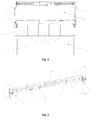
- Fig. 1 is a schematic view showing the opening and closing of the paper money transporting and storing device according to the present invention
- Fig. 2 is a perspective view of the locking mechanism in the paper money transporting and storing device
- Fig. 3 is a partial enlarged view of part A in Fig. 2 ;
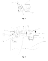
- Fig. 4 is a right view of the paper money transporting and storing device showing the closed state of the passage
- Fig. 5 is a right view of the paper money transporting and storing device showing the open state of the passage
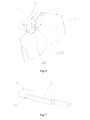
- Fig. 6 is a schematic view showing the operating of the assistant positioning mechanism between the paper money transporting passage and the cashbox assembly in the present invention
- Fig. 7 is a schematic view of the rotation stop sheet assembly between the paper money transporting passage and the cashbox assembly according to the present invention.
- Fig. 8 is a schematic view of the detecting mechanism for detecting whether the transporting passage is closed in position relative to the cashbox assembly in the present invention.
- the paper money transporting and storing device includes a paper money transporting passage 1 and a cashbox assembly 2 for storing paper money.
- the cashbox assembly 2 is disposed within a cashbox assembly bracket 21.
- the cashbox assembly bracket 21 is a box body, one surface of which may be covered by turning the paper money transporting passage 1.
- One end of the paper money transporting passage 1 is pivoted to a side wall 211 of the cashbox assembly bracket 21 through a pivot shaft 11.
- a locking mechanism 3 is provided at an end of the paper money transporting passage 1 opposite to the pivoted end.
- the upper portion of a side wall 213 of the cashbox assembly bracket 21 corresponding to the locking mechanism 3 is open.
- the open side wall 213 of the cashbox assembly bracket 21 is designed such that a cashbox 22 may be drawn out easily when replacing the cashbox 22 so as to reduce the labor intensity, which is conveniently used.
- the locking mechanism 3 includes: a fixed bracket 31 which is fixed to the end of the paper money transporting passage in order to install and support components necessary for locking; a long locking member which includes a rotation shaft 32 extending across the opposite end surfaces of the fixed bracket 31 and locking hooks 33 fixed to both ends of the rotation shaft 32, wherein an openable connection is formed between the locking hooks 33 and locking pins 2121 provided on side walls 212 of the cashbox assembly bracket 21; an unlocking handle 34 which is fixed to the rotation shaft 32 in order to drive the rotation shaft 32 to freely rotate so that the locking hooks 33 are driven to be engaged with or disengaged from corresponding locking pins 2121.
- support members 35 are provided at appropriate positions of middle portion of the rotation shaft and properly support the rotation shaft 32 so as to allow the rotation shaft to become more stable.
- return torsion springs 36 for providing return force after the locking hooks 33 are disengaged from the engagement position are disposed on the rotation shaft 32 and configured to surround the rotation shaft 32.
- One end of each return torsion spring is fixed to the fixed bracket 31 and the other end is fixed to the locking hook 33.
- a passage handle 37 is provided on the locking mechanism, so as to facilitate the opening and closing operation of the paper money transporting passage.
- a schematic view showing the operating of the assistant positioning mechanism between the paper money transporting passage and the cashbox assembly in the present invention is shown.
- a positioning hole 121 is provided in the side wall 12 of the paper money transporting passage 1
- a positioning pin 2122 corresponding to the positioning hole 121 is provided on the corresponding side wall 212 of the cashbox assembly bracket 21.
- the positioning pin 2122 precisely passes through the positioning hole 121, such that the paper money transporting passage 1 is closed in position relative to the cashbox assembly bracket 21. Therefore, a precise connection is achieved between the paper money transporting passage 1 and the cashbox assembly so as to ensure the smooth transportation of paper money.
- gas springs 4 for assisting to open the paper money transporting passage are provided between the paper money transporting passage 1 and the cashbox assembly bracket 21 in order to easily open the paper money transporting passage.
- One end 41 of each gas spring is pivoted to the side wall of the paper money transporting passage 1 and the other end 42 is pivoted to corresponding side wall 212 of the cashbox assembly bracket.
- a turning stop mechanism is provided between the paper money transporting passage 1 and the cashbox assembly bracket 21.
- the turning stop mechanism includes a stop sheet 5.
- An end 51 of the stop sheet 5 is pivoted to the side wall 212 of the cashbox assembly bracket.
- a stop pin 53 is provided on the surface of the other end 52 of the stop sheet 5 facing the paper money transporting passage 1.
- a sliding groove 14 is provided on the side wall of the paper money transporting passage 1 corresponding to the stop pin 53 and is parallel to the plane of the transporting passage.
- An upward angled location groove 141 is formed at the end of the sliding groove 14 near the pivot shaft 11 of the transporting passage, and used to reliably stop the transporting passage 1 when the transporting passage 1 is opened in position.
- a releasing manipulator 54 is provided at the end of the stop sheet near the stop pin 53 to easily release the stop sheet when the paper money transporting passage 1 is to be closed.
- a transporting passage closed in-position detecting mechanism 6 is provided on the side wall 212 of the cashbox assembly bracket 21.
- the detecting mechanism 6 includes a U-shape sensor 61, a rotation member 62 and a return torsion spring 63 for automatically returning the rotation member 62.
- the rotation member 62 includes a check plate 621 capable of entering into the U-shape sensor 61.
- the rotation member 62 is pivoted to a sensor supporter 65 through a pivot shaft 64. The whole sensor is fixed to the side wall 212 of the cashbox assembly bracket by way of the supporter 65.
- the return torsion spring 63 is configured to surround the pivot shaft 64. One end of the return torsion spring 63 is fixed to the rotation member 62, and the other end is fixed to the sensor supporter 65.
- a paper money transporting passage pressing handle 622 is provided at one end of the rotation member 62 opposite to the sensor check plate 621. The pressing handle 622 and the sensor check plate 621 forms a V-shape rotation member. When the paper money transporting passage 1 is closed in position, the transporting passage presses the pressing handle 622 so as to rotate the V-shape rotation member around the pivot shaft 64, such that the sensor check plate 621 departs from the U-shape sensor 61.
- a control centre of the system may determine whether the paper money transporting passage is closed in position. In the embodiment, when the U-shape sensor is blocked, it is determined that the paper money transporting passage isn't closed, and when the U-shape sensor isn't blocked, it is determined that the paper money transporting passage is closed in position.
Landscapes
- Engineering & Computer Science (AREA)
- Mechanical Engineering (AREA)
- Physics & Mathematics (AREA)
- General Physics & Mathematics (AREA)
- Pile Receivers (AREA)
- Cash Registers Or Receiving Machines (AREA)
Abstract
Description
- The present application claims the benefit of priority to Chinese patent application No.
200910193047.3 - The present invention relates to a paper money transporting and storing device, and more particular to a paper money transporting passage and a storing device having a locking mechanism used in a financial instrument.
- Existing financial self-service terminal includes the cash deposit machine, the automatic teller machine and the automatic depositing and withdrawing system. In these machines which may directly deal with paper currency, in order to achieve the exchange of paper money between the user and the machine, it is necessary to install a paper money transporting passage device in these machines. The device is used to transport paper money to be deposited into the self-service instrument by user to the terminal cashbox and/or transport paper money in the terminal cashbox to the user.
- Particularly, the paper money transporting passage device in the automatic depositing and withdrawing system is used to transport the notes dispensed by an upper machine mechanism and store the notes into the cashbox, or transport the paper money storing in the cashbox to the upper machine mechanism to be dispensed. The upper machine mechanism includes a paper money identifying device, a paper money temporarily storing device and a paper money collecting device. The paper money collecting device allows the user to take out paper money or put in paper money. A lower machine mechanism includes a cashbox assembly for storing paper money. A paper money transporting passage is provided between the upper machine mechanism and the cashbox assembly of the lower machine mechanism. Generally, the paper money transporting passage covers and is pressed on the cashbox so as to achieve a precise positioning and aligning between the transporting passage and a paper money inlet/outlet of the cashbox, thereby ensuring the smooth transportation of paper money.
- The conventional method for fixing the paper money transporting passage device to the cashbox assembly of the lower machine mechanism is generally that the transporting passage device is pressed by the upper machine mechanism and then closed with the side walls of the cashbox assembly bracket for the lower machine mechanism, so as to position and fix the transporting passage. In this method, the positioning between the transporting passage and the cashbox is achieved by the cooperation between bearings installed on the passage and a floating elastic sheet installed on an associated safe cabinet. When the lower machine mechanism is pushed into, the transporting passage is pressed by the floating elastic sheet and tightly fitted with the side walls of the cashbox assembly bracket for the lower machine mechanism.
- In view of the above fixing method, the fastening of the transporting passage is achieved by a clamp force formed from the downward pressure of the floating elastic sheet on the safe cabinet towards the components below the transporting passage. However, the cashbox below the transporting passage is not applicable to support the transporting passage. Thus, the transporting passage is needed to be supported by side walls of an additional cashbox bracket. Therefore, it is required to lift the cashbox by a large height when replacing the cashbox, which increases the labor intensity of the operator and is inconvenient for use.
- In addition, the transporting passage is fastened by cooperation between bearings installed on the passage and the floating elastic sheet installed on associated safe cabinet. When the lower machine mechanism is pushed into, the passage is pressed in position, which certainly influences the independency of the lower machine mechanism. Besides, the structure of the opening-closing mechanism of this transporting passage is relatively complex, and is inconvenient for use.
- In view of the problems of non-independency, inconvenient operation of the transporting passage and the problem of insufficient reliability in positioning between the transporting passage and the cashbox, the present invention provides a paper money transporting and storing device having a long locking mechanism.
- The object of the present invention is achieved by the following solutions.
- The paper money transporting and storing device includes a paper money transporting passage and a cashbox assembly for storing paper money. The cashbox assembly is disposed within a cashbox assembly bracket. The cashbox assembly bracket is a box body, one surface of which may be covered by turning the paper money transporting passage. One end of the paper money transporting passage is pivoted to a side wall of the cashbox assembly bracket. A locking mechanism is provided at the other end of the paper money transporting passage opposite to the pivoted end. The locking mechanism includes: a fixed bracket, which is fixed to the other end of the paper money transporting passage in order to install and support components necessary for locking; a long locking member, which includes a rotation shaft extending across opposite end surfaces of the fixed bracket and locking hooks fixed to both ends of the rotation shaft, wherein an openable connection is formed between the locking hooks and locking pins correspondingly provided on side walls of the cashbox assembly bracket; and an unlocking handle, which is fixed to the rotation shaft in order to drive the rotation shaft to freely rotate so that the locking hooks are driven to be engaged with or disengaged from corresponding locking pins.
- Preferably, a return torsion spring is provided on the rotation shaft. One end of the return torsion spring is fixed to the fixed bracket, and the other end of the return torsion spring is fixed relative to the rotation shaft, so as to provide return force after the locking hooks are disengaged from an engagement position.
- Preferably, a positioning assistant member having a positioning hole is provided on the side wall of the paper money transporting passage, and a positioning pin corresponding to the positioning hole is provided on corresponding side wall of the cashbox assembly bracket.
- Preferably, a gas spring is provided between the paper money transporting passage and the cashbox assembly bracket. One end of the gas spring is pivoted to the side wall of the paper money transporting passage, and the other end of the gas spring is pivoted to corresponding side wall of the cashbox assembly bracket.
- Preferably, a turning stop mechanism is provided between the paper money transporting passage and the cashbox assembly bracket. The turning stop mechanism includes a stop sheet. One end of the stop sheet is pivoted to the side wall of the cashbox assembly bracket. A stop pin is provided on a surface of the other end of the stop sheet facing the paper money transporting passage. A sliding groove is provided on the side wall of the paper money transporting passage corresponding to the stop pin and is parallel to the plane of the transporting passage. An upward angled location groove is formed at the end of the sliding groove near the pivot shaft of the transporting passage and used to reliably stop the transporting passage when the transporting passage is opened in position.
- Preferably, a transporting passage closed in-position detecting mechanism is provided on the side wall of the cashbox assembly bracket.
- Further, the detecting mechanism includes a U-shape sensor, a rotation member and a return torsion spring for returning the rotation member. The rotation member has a check plate capable of entering into the U-shape sensor.
- Further, the rotation member is pivoted to the side wall of the cashbox assembly bracket through a pivot shaft. The return torsion spring is surroundingly connected to the pivot shaft. One end of the return torsion spring is fixed to the rotation member, and the other end of the return torsion spring is fixed to the pivot shaft or a fixing mechanism of the pivot shaft.
- Further, a paper money transporting passage pressing handle is provided at one end of the rotation member opposite to the sensor check plate. The pressing handle and the sensor check plate form a V-shape rotation member. When the paper money transporting passage is closed in position, the transporting passage presses the pressing handle so as to rotate the V-shape rotation member around the pivot shaft, such that the sensor check plate departs from the U-shape sensor. After the paper money transporting passage is opened, the V-shape rotation member is rotated in a reverse direction by the return torsion spring, such that the sensor check plate enters into the U-shape sensor.
- Preferably, the cashbox assembly bracket is configured to be open at an upper portion of the side wall thereof corresponding to the locking mechanism.
- Therefore, compared with the prior art, the paper money transporting and storing device according to the present invention has the following advantages:
- First, the cashbox may be easily drawn out when replacing owning to the open design of the side wall of the cashbox assembly bracket, which reduces the labor intensity and is conveniently used.
- Second, the paper money transporting passage may be entirely positioned by the cashbox assembly bracket, such that the paper money transporting passage and the storing device become independent modules, which reduces the requirements of the cooperation between them and the other modules and is conveniently installed.
- Third, it is more convenient and safe to open or close the paper money transporting passage by using the assistant gas spring and the turning stop mechanism.
- Fourth, the transporting passage closed in-position detecting mechanism may ensure that the passage is closed in position, so as to engage smoothly between the cashbox and the transporting passage, thereby ensuring the smooth transportation of paper money.
-
Fig. 1 is a schematic view showing the opening and closing of the paper money transporting and storing device according to the present invention; -
Fig. 2 is a perspective view of the locking mechanism in the paper money transporting and storing device; -
Fig. 3 is a partial enlarged view of part A inFig. 2 ; -
Fig. 4 is a right view of the paper money transporting and storing device showing the closed state of the passage; -
Fig. 5 is a right view of the paper money transporting and storing device showing the open state of the passage; -
Fig. 6 is a schematic view showing the operating of the assistant positioning mechanism between the paper money transporting passage and the cashbox assembly in the present invention; -
Fig. 7 is a schematic view of the rotation stop sheet assembly between the paper money transporting passage and the cashbox assembly according to the present invention; and -
Fig. 8 is a schematic view of the detecting mechanism for detecting whether the transporting passage is closed in position relative to the cashbox assembly in the present invention. - Hereinafter, the technical solutions in embodiments of the present invention will be described clearly and completely with reference to drawings of the embodiments of the present invention. It is apparent that the embodiments to be described are merely a portion of embodiments of the present invention, but not all of the embodiments. Based on the embodiments of the present invention, all of other embodiments made by those skilled in the art without inventive effort fall into the protection scope of the present invention.
- Referring to
Figs. 1 ,4 and5 , schematic views of a paper money transporting and storing device are shown. The paper money transporting and storing device includes a paper money transporting passage 1 and acashbox assembly 2 for storing paper money. Thecashbox assembly 2 is disposed within acashbox assembly bracket 21. Thecashbox assembly bracket 21 is a box body, one surface of which may be covered by turning the paper money transporting passage 1. One end of the paper money transporting passage 1 is pivoted to a side wall 211 of thecashbox assembly bracket 21 through apivot shaft 11. A locking mechanism 3 is provided at an end of the paper money transporting passage 1 opposite to the pivoted end. The upper portion of aside wall 213 of thecashbox assembly bracket 21 corresponding to the locking mechanism 3 is open. Theopen side wall 213 of thecashbox assembly bracket 21 is designed such that acashbox 22 may be drawn out easily when replacing thecashbox 22 so as to reduce the labor intensity, which is conveniently used. - Referring to
Figs. 2 and3 , the locking mechanism 3 includes: a fixedbracket 31 which is fixed to the end of the paper money transporting passage in order to install and support components necessary for locking; a long locking member which includes arotation shaft 32 extending across the opposite end surfaces of the fixedbracket 31 and locking hooks 33 fixed to both ends of therotation shaft 32, wherein an openable connection is formed between the locking hooks 33 and lockingpins 2121 provided onside walls 212 of thecashbox assembly bracket 21; an unlockinghandle 34 which is fixed to therotation shaft 32 in order to drive therotation shaft 32 to freely rotate so that the locking hooks 33 are driven to be engaged with or disengaged from corresponding locking pins 2121. In the embodiment, since the locking member has a relatively long span,support members 35 are provided at appropriate positions of middle portion of the rotation shaft and properly support therotation shaft 32 so as to allow the rotation shaft to become more stable. In order that the locking mechanism 3 may be self-locked, return torsion springs 36 for providing return force after the locking hooks 33 are disengaged from the engagement position are disposed on therotation shaft 32 and configured to surround the rotation shaft 32.One end of each return torsion spring is fixed to the fixedbracket 31 and the other end is fixed to the lockinghook 33. In addition, in order to easily turn and open the paper money transporting passage, apassage handle 37 is provided on the locking mechanism, so as to facilitate the opening and closing operation of the paper money transporting passage. - Referring to
Fig. 6 , a schematic view showing the operating of the assistant positioning mechanism between the paper money transporting passage and the cashbox assembly in the present invention is shown. In order to achieve a precise positioning between the paper money transporting passage 1 and thecashbox assembly 2, apositioning hole 121 is provided in theside wall 12 of the paper money transporting passage 1, and apositioning pin 2122 corresponding to thepositioning hole 121 is provided on thecorresponding side wall 212 of thecashbox assembly bracket 21. When the paper money transporting passage 1 is closed relative to thecashbox assembly bracket 21, thepositioning pin 2122 precisely passes through thepositioning hole 121, such that the paper money transporting passage 1 is closed in position relative to thecashbox assembly bracket 21. Therefore, a precise connection is achieved between the paper money transporting passage 1 and the cashbox assembly so as to ensure the smooth transportation of paper money. - Referring to
Figs. 4 and5 , since the paper money transporting passage 1 is relatively heavy, gas springs 4 for assisting to open the paper money transporting passage are provided between the paper money transporting passage 1 and thecashbox assembly bracket 21 in order to easily open the paper money transporting passage. Oneend 41 of each gas spring is pivoted to the side wall of the paper money transporting passage 1 and theother end 42 is pivoted to correspondingside wall 212 of the cashbox assembly bracket. When the paper money transporting passage 1 is to be opened, the unlockinghandle 34 on therotation shaft 32 of the locking mechanism 3 is drawn, and therotation shaft 32 is rotated and then drives the locking hooks 33 to rotate, as a result, the locking hooks 33 are disengaged from the locking pins 2121. At this moment, the paper money transporting passage 1 is opened around thepivot shaft 14 under a lifting elastic force of thegas spring 4. - Referring to
Figs. 4 ,5 and7 , in order to limit the opening stroke of the paper money transporting passage 1, a turning stop mechanism is provided between the paper money transporting passage 1 and thecashbox assembly bracket 21. The turning stop mechanism includes astop sheet 5. Anend 51 of thestop sheet 5 is pivoted to theside wall 212 of the cashbox assembly bracket. Astop pin 53 is provided on the surface of the other end 52 of thestop sheet 5 facing the paper money transporting passage 1. A slidinggroove 14 is provided on the side wall of the paper money transporting passage 1 corresponding to thestop pin 53 and is parallel to the plane of the transporting passage. An upwardangled location groove 141 is formed at the end of the slidinggroove 14 near thepivot shaft 11 of the transporting passage, and used to reliably stop the transporting passage 1 when the transporting passage 1 is opened in position. In addition, a releasingmanipulator 54 is provided at the end of the stop sheet near thestop pin 53 to easily release the stop sheet when the paper money transporting passage 1 is to be closed. - Referring to
Figs. 4 ,5 and8 , in order to detect whether the paper money transporting passage 1 is closed in position relative to the cashbox assembly, a transporting passage closed in-position detecting mechanism 6 is provided on theside wall 212 of thecashbox assembly bracket 21. The detectingmechanism 6 includes aU-shape sensor 61, arotation member 62 and areturn torsion spring 63 for automatically returning therotation member 62. Therotation member 62 includes acheck plate 621 capable of entering into theU-shape sensor 61. Therotation member 62 is pivoted to asensor supporter 65 through apivot shaft 64. The whole sensor is fixed to theside wall 212 of the cashbox assembly bracket by way of thesupporter 65. Thereturn torsion spring 63 is configured to surround thepivot shaft 64. One end of thereturn torsion spring 63 is fixed to therotation member 62, and the other end is fixed to thesensor supporter 65. A paper money transportingpassage pressing handle 622 is provided at one end of therotation member 62 opposite to thesensor check plate 621. Thepressing handle 622 and thesensor check plate 621 forms a V-shape rotation member. When the paper money transporting passage 1 is closed in position, the transporting passage presses thepressing handle 622 so as to rotate the V-shape rotation member around thepivot shaft 64, such that thesensor check plate 621 departs from theU-shape sensor 61. After the paper money transporting passage 1 is opened, the V-shape rotation member is rotated in a reverse direction by thereturn torsion spring 63, such that thesensor check plate 621 enters into theU-shape sensor 61. According to information whether the U-shape sensor is blocked, a control centre of the system (not shown) may determine whether the paper money transporting passage is closed in position. In the embodiment, when the U-shape sensor is blocked, it is determined that the paper money transporting passage isn't closed, and when the U-shape sensor isn't blocked, it is determined that the paper money transporting passage is closed in position. - While the preferred embodiments of the present invention have been described above, it is not intended to limit the protection scope of the present invention. Therefore, various equivalent variations made by those skilled in the art based on the contents described in the Description and illustrated in drawings of the present invention are deemed to fall into the protection scope of the present invention.
Claims (10)
- A paper money transporting and storing device, comprising a paper money transporting passage and a cashbox assembly for storing paper money, wherein the cashbox assembly is disposed within a cashbox assembly bracket, the cashbox assembly bracket is a box body, one surface of which may be covered by turning the paper money transporting passage, one end of the paper money transporting passage is pivoted to a side wall of the cashbox assembly bracket,
characterized in that a locking mechanism is provided at the other end of the paper money transporting passage opposite to the pivoted end, and the locking mechanism comprises:a fixed bracket, which is fixed to the other end of the paper money transporting passage in order to install and support components necessary for locking;a long locking member, which comprises a rotation shaft extending across opposite end surfaces of the fixed bracket and locking hooks fixed to both ends of the rotation shaft, wherein an openable connection is formed between the locking hooks and locking pins correspondingly provided on side walls of the cashbox assembly bracket; andan unlocking handle, which is fixed to the rotation shaft in order to drive the rotation shaft to freely rotate so that the locking hooks are driven to be engaged with or disengaged from corresponding locking pins. - The paper money transporting and storing device according to claim 1, wherein a return torsion spring is provided on the rotation shaft, one end of the return torsion spring is fixed to the fixed bracket, and the other end of the return torsion spring is fixed relative to the rotation shaft, so as to provide return force after the locking hooks are disengaged from an engagement position.
- The paper money transporting and storing device according to claim 1, wherein a positioning assistant member having a positioning hole is provided on the side wall of the paper money transporting passage, and a positioning pin corresponding to the positioning hole is provided on corresponding side wall of the cashbox assembly bracket.
- The paper money transporting and storing device according to claim 1, wherein a gas spring is provided between the paper money transporting passage and the cashbox assembly bracket, one end of the gas spring is pivoted to the side wall of the paper money transporting passage, the other end of the gas spring is pivoted to corresponding side wall of the cashbox assembly bracket.
- The paper money transporting and storing device according to claim 1, wherein a turning stop mechanism is provided between the paper money transporting passage and the cashbox assembly bracket, the turning stop mechanism comprises a stop sheet, one end of the stop sheet is pivoted to the side wall of the cashbox assembly bracket, a stop pin is provided on a surface of the other end of the stop sheet facing the paper money transporting passage, a sliding groove is provided on the side wall of the paper money transporting passage corresponding to the stop pin and is parallel to the plane of the transporting passage, an upward angled location groove is formed at the end of the sliding groove near the pivot shaft of the transporting passage and used to reliably stop the transporting passage when the transporting passage is opened in position.
- The paper money transporting and storing device according to claim 1, wherein a transporting passage closed in-position detecting mechanism is provided on the side wall of the cashbox assembly bracket.
- The paper money transporting and storing device according to claim 6, wherein the detecting mechanism comprises a U-shape sensor, a rotation member and a return torsion spring for returning the rotation member, the rotation member has a check plate capable of entering into the U-shape sensor.
- The paper money transporting and storing device according to claim 7, wherein the rotation member is pivoted to the side wall of the cashbox assembly bracket through a pivot shaft, the return torsion spring is surroundingly connected to the pivot shaft, one end of the return torsion spring is fixed to the rotation member, the other end of the return torsion spring is fixed to the pivot shaft or a fixing mechanism of the pivot shaft.
- The paper money transporting and storing device according to claim 7, wherein a paper money transporting passage pressing handle is provided at one end of the rotation member opposite to the sensor check plate, and
wherein the pressing handle and the sensor check plate form a V-shape rotation member, when the paper money transporting passage is closed in position, the transporting passage presses the pressing handle so as to rotate the V-shape rotation member around the pivot shaft, such that the sensor check plate departs from the U-shape sensor; and after the paper money transporting passage is opened, the V-shape rotation member is rotated in a reverse direction by the return torsion spring, such that the sensor check plate enters into the U-shape sensor. - The paper money transporting and storing device according to claim 1, wherein the cashbox assembly bracket is configured to be open at an upper portion of the side wall thereof corresponding to the locking mechanism.
Applications Claiming Priority (2)
| Application Number | Priority Date | Filing Date | Title |
|---|---|---|---|
| CN2009101930473A CN102044110B (en) | 2009-10-13 | 2009-10-13 | Paper currency transmission and storage device |
| PCT/CN2010/077135 WO2011044814A1 (en) | 2009-10-13 | 2010-09-20 | Paper money transmission and storage device |
Publications (3)
| Publication Number | Publication Date |
|---|---|
| EP2472481A1 true EP2472481A1 (en) | 2012-07-04 |
| EP2472481A4 EP2472481A4 (en) | 2013-08-07 |
| EP2472481B1 EP2472481B1 (en) | 2017-06-21 |
Family
ID=43875832
Family Applications (1)
| Application Number | Title | Priority Date | Filing Date |
|---|---|---|---|
| EP10823044.2A Not-in-force EP2472481B1 (en) | 2009-10-13 | 2010-09-20 | Paper money transmission and storage device |
Country Status (5)
| Country | Link |
|---|---|
| US (1) | US8534441B2 (en) |
| EP (1) | EP2472481B1 (en) |
| CN (1) | CN102044110B (en) |
| AU (1) | AU2010306269B2 (en) |
| WO (1) | WO2011044814A1 (en) |
Cited By (2)
| Publication number | Priority date | Publication date | Assignee | Title |
|---|---|---|---|---|
| CN103325173A (en) * | 2013-06-03 | 2013-09-25 | 长城信息产业股份有限公司 | Self-locking opening mechanism of note case |
| CN103996244A (en) * | 2014-05-22 | 2014-08-20 | 浙江方泰电器有限公司 | Money inlet damp wheel train support of sorting machine |
Families Citing this family (17)
| Publication number | Priority date | Publication date | Assignee | Title |
|---|---|---|---|---|
| JP5929273B2 (en) * | 2012-02-07 | 2016-06-01 | 沖電気工業株式会社 | Medium storage device |
| JP6031792B2 (en) * | 2012-03-29 | 2016-11-24 | 沖電気工業株式会社 | Automatic teller machine |
| CN103116938A (en) * | 2013-01-11 | 2013-05-22 | 广州广电运通金融电子股份有限公司 | Bill stacking device |
| CN105574989B (en) * | 2014-10-11 | 2018-05-04 | 聚龙股份有限公司 | A kind of two-way paper money arrangement mechanism |
| CN104851187A (en) * | 2015-06-08 | 2015-08-19 | 广州御银自动柜员机技术有限公司 | Movement limiting structure |
| CN105023343B (en) * | 2015-07-15 | 2017-11-07 | 深圳怡化电脑股份有限公司 | Lower channel module and cash box docking structure |
| CN105551136B (en) * | 2016-02-05 | 2017-12-15 | 重庆理工大学 | One kind rubs the automatic flattening device of fraction bank note with the hands |
| CN105666443A (en) * | 2016-04-15 | 2016-06-15 | 上海麦源实业有限公司 | Tool box with anti-bumping lock mechanism |
| CN106327669A (en) * | 2016-08-12 | 2017-01-11 | 深圳怡化电脑股份有限公司 | Money depositing and withdrawing device and money depositing and withdrawing equipment ATM and VTM |
| CN106340118B (en) * | 2016-08-22 | 2022-11-25 | 深圳怡化电脑股份有限公司 | Locking device and automatic teller machine |
| CN106846618B (en) * | 2017-02-15 | 2023-04-07 | 深圳怡化电脑股份有限公司 | Positioning device for upper and lower movement of cash recycling machine and cash recycling machine |
| CN107341937B (en) * | 2017-06-13 | 2019-08-13 | 东方通信股份有限公司 | A kind of open-and-close mechanism for paper medium transmission |
| CN107191072A (en) * | 2017-07-05 | 2017-09-22 | 深圳怡化电脑股份有限公司 | Locking structure, medium collection device, locking method and unlocking method |
| CN107862788B (en) * | 2017-11-22 | 2024-06-14 | 深圳怡化电脑股份有限公司 | Medium authentication terminal and self-service financial terminal |
| CN108961608B (en) * | 2018-08-27 | 2023-10-13 | 北京兆维电子(集团)有限责任公司 | Bankbook bin and automatic bankbook issuing equipment comprising same |
| CN110675547B (en) * | 2019-10-10 | 2024-12-17 | 维融科技股份有限公司 | Cash adding machine |
| CN116146052A (en) * | 2023-04-19 | 2023-05-23 | 华夏技术(临沂)有限公司 | Cashier box |
Family Cites Families (15)
| Publication number | Priority date | Publication date | Assignee | Title |
|---|---|---|---|---|
| US3600023A (en) * | 1970-02-09 | 1971-08-17 | Rohr Corp | Locking system |
| US4784414A (en) * | 1987-08-28 | 1988-11-15 | Coachmen Industries, Inc. | Latch mechanism |
| DE3812370C1 (en) * | 1988-04-14 | 1989-10-05 | Christian Geyer Gmbh & Co, 8500 Nuernberg, De | Electrical distribution cabinet, especially a cable distribution cabinet |
| DE4005291C2 (en) * | 1989-02-22 | 1995-06-29 | Nsm Ag | Device for checking and storing banknotes in a self-cashing machine |
| CA2360253C (en) * | 2000-11-01 | 2005-08-02 | Lg Electronics Inc. | Media cassette for automatic dispenser |
| FR2827331B1 (en) * | 2001-07-13 | 2004-03-05 | Ecodis Sa | DEVICE FOR ARTICULATING AND LOCKING A FRAME ON A CHASSIS BY MEANS OF A JACK |
| US7516832B2 (en) * | 2003-08-20 | 2009-04-14 | Ellenby Technologies, Inc. | Two door electronic safe |
| CN2698472Y (en) | 2004-05-24 | 2005-05-11 | 邱林 | Horizontal paper banknote classifying machine |
| TWI290307B (en) * | 2004-06-01 | 2007-11-21 | Hitachi Omron Terminal Solutions Corp | Bill depositing/dispensing apparatus |
| JP4704777B2 (en) | 2004-06-01 | 2011-06-22 | 日立オムロンターミナルソリューションズ株式会社 | Banknote deposit and withdrawal machine |
| JP4716683B2 (en) | 2004-06-07 | 2011-07-06 | 株式会社オーイズミ | Banknote transfer device |
| JP2006143383A (en) * | 2004-11-18 | 2006-06-08 | Aruze Corp | Banknote handling device and banknote storage unit |
| CN1796259A (en) * | 2004-12-24 | 2006-07-05 | 鈊象电子股份有限公司 | paper storage box |
| KR100721647B1 (en) | 2006-05-17 | 2007-05-23 | 노틸러스효성 주식회사 | 2 paragraph structure of automatic teller machine |
| CN201035639Y (en) * | 2007-04-13 | 2008-03-12 | 广州市地下铁道总公司 | Locking mechanism of coin recovery case |
-
2009
- 2009-10-13 CN CN2009101930473A patent/CN102044110B/en active Active
-
2010
- 2010-09-20 AU AU2010306269A patent/AU2010306269B2/en not_active Ceased
- 2010-09-20 WO PCT/CN2010/077135 patent/WO2011044814A1/en not_active Ceased
- 2010-09-20 US US13/500,283 patent/US8534441B2/en not_active Expired - Fee Related
- 2010-09-20 EP EP10823044.2A patent/EP2472481B1/en not_active Not-in-force
Cited By (3)
| Publication number | Priority date | Publication date | Assignee | Title |
|---|---|---|---|---|
| CN103325173A (en) * | 2013-06-03 | 2013-09-25 | 长城信息产业股份有限公司 | Self-locking opening mechanism of note case |
| CN103325173B (en) * | 2013-06-03 | 2015-08-19 | 长城信息产业股份有限公司 | A kind of ticket fee case self-locking door-opening mechanism |
| CN103996244A (en) * | 2014-05-22 | 2014-08-20 | 浙江方泰电器有限公司 | Money inlet damp wheel train support of sorting machine |
Also Published As
| Publication number | Publication date |
|---|---|
| CN102044110A (en) | 2011-05-04 |
| AU2010306269A1 (en) | 2012-05-10 |
| US8534441B2 (en) | 2013-09-17 |
| CN102044110B (en) | 2013-09-25 |
| WO2011044814A1 (en) | 2011-04-21 |
| EP2472481B1 (en) | 2017-06-21 |
| US20120199053A1 (en) | 2012-08-09 |
| AU2010306269B2 (en) | 2013-08-15 |
| EP2472481A4 (en) | 2013-08-07 |
Similar Documents
| Publication | Publication Date | Title |
|---|---|---|
| US8534441B2 (en) | Paper money transmission and storage device | |
| US8517479B2 (en) | Apparatus for opening and closing the shield plate of automated teller machine | |
| KR101148387B1 (en) | Automatic cash transaction device | |
| KR101001695B1 (en) | Shutter opening and closing device of automatic teller machine | |
| EP3032506B1 (en) | Teller cash recycler | |
| US20140217669A1 (en) | Paper sheet processing device | |
| RU2551077C2 (en) | Drawer device and device for transactions with media | |
| EP2600322B1 (en) | Medium storage box | |
| KR101171460B1 (en) | Push plate up and down structure in bill stacking box | |
| KR101628206B1 (en) | Teller cash recycler | |
| US7044331B2 (en) | Media dispenser module and automated teller machine having the same | |
| US20220207948A1 (en) | Banknote Conveying Module and Banknote Adding Machine Thereof | |
| KR101628204B1 (en) | Teller cash recycler | |
| JP2010182127A (en) | Automatic teller machine | |
| KR20200095256A (en) | Automated cash receiving apparatus | |
| KR20070028058A (en) | Banknote Storage | |
| KR101988058B1 (en) | Automated Teller Machine with a structure capable of maintenance easily | |
| KR102854703B1 (en) | Bill storage device for easy maintenance | |
| KR101153874B1 (en) | Financial automated-teller machine having support device of opening frame | |
| KR101041296B1 (en) | Residual Media Recovery Device of Media Dispenser | |
| JPH06162318A (en) | Bill validator | |
| JP2001134840A (en) | Paper money receiving/paying-out device | |
| KR20050071235A (en) | Plate locker of the auto teller machine recycle-box | |
| KR20070068550A (en) | Banknote Storage Box Fixing Device | |
| KR100610999B1 (en) | Withdrawal control device and method of the withdrawal machine in the banknote machine |
Legal Events
| Date | Code | Title | Description |
|---|---|---|---|
| PUAI | Public reference made under article 153(3) epc to a published international application that has entered the european phase |
Free format text: ORIGINAL CODE: 0009012 |
|
| 17P | Request for examination filed |
Effective date: 20120329 |
|
| AK | Designated contracting states |
Kind code of ref document: A1 Designated state(s): AL AT BE BG CH CY CZ DE DK EE ES FI FR GB GR HR HU IE IS IT LI LT LU LV MC MK MT NL NO PL PT RO SE SI SK SM TR |
|
| DAX | Request for extension of the european patent (deleted) | ||
| A4 | Supplementary search report drawn up and despatched |
Effective date: 20130705 |
|
| RIC1 | Information provided on ipc code assigned before grant |
Ipc: E05B 47/00 20060101ALI20130701BHEP Ipc: G07D 11/00 20060101ALI20130701BHEP Ipc: G07D 13/00 20060101AFI20130701BHEP |
|
| 17Q | First examination report despatched |
Effective date: 20151113 |
|
| REG | Reference to a national code |
Ref country code: DE Ref legal event code: R079 Ref document number: 602010043184 Country of ref document: DE Free format text: PREVIOUS MAIN CLASS: G07D0013000000 Ipc: E05G0007000000 |
|
| RIC1 | Information provided on ipc code assigned before grant |
Ipc: E05C 9/00 20060101ALI20161122BHEP Ipc: E05F 1/10 20060101ALI20161122BHEP Ipc: E05C 17/24 20060101ALI20161122BHEP Ipc: E05C 9/08 20060101ALI20161122BHEP Ipc: G07D 11/00 20060101ALI20161122BHEP Ipc: E05G 7/00 20060101AFI20161122BHEP Ipc: E05D 13/00 20060101ALI20161122BHEP Ipc: E05B 47/00 20060101ALI20161122BHEP |
|
| GRAP | Despatch of communication of intention to grant a patent |
Free format text: ORIGINAL CODE: EPIDOSNIGR1 |
|
| INTG | Intention to grant announced |
Effective date: 20170105 |
|
| GRAS | Grant fee paid |
Free format text: ORIGINAL CODE: EPIDOSNIGR3 |
|
| GRAA | (expected) grant |
Free format text: ORIGINAL CODE: 0009210 |
|
| AK | Designated contracting states |
Kind code of ref document: B1 Designated state(s): AL AT BE BG CH CY CZ DE DK EE ES FI FR GB GR HR HU IE IS IT LI LT LU LV MC MK MT NL NO PL PT RO SE SI SK SM TR |
|
| REG | Reference to a national code |
Ref country code: GB Ref legal event code: FG4D |
|
| REG | Reference to a national code |
Ref country code: CH Ref legal event code: EP |
|
| REG | Reference to a national code |
Ref country code: IE Ref legal event code: FG4D |
|
| REG | Reference to a national code |
Ref country code: AT Ref legal event code: REF Ref document number: 903103 Country of ref document: AT Kind code of ref document: T Effective date: 20170715 |
|
| REG | Reference to a national code |
Ref country code: DE Ref legal event code: R096 Ref document number: 602010043184 Country of ref document: DE |
|
| REG | Reference to a national code |
Ref country code: FR Ref legal event code: PLFP Year of fee payment: 8 |
|
| REG | Reference to a national code |
Ref country code: NL Ref legal event code: MP Effective date: 20170621 |
|
| PG25 | Lapsed in a contracting state [announced via postgrant information from national office to epo] |
Ref country code: LT Free format text: LAPSE BECAUSE OF FAILURE TO SUBMIT A TRANSLATION OF THE DESCRIPTION OR TO PAY THE FEE WITHIN THE PRESCRIBED TIME-LIMIT Effective date: 20170621 Ref country code: NO Free format text: LAPSE BECAUSE OF FAILURE TO SUBMIT A TRANSLATION OF THE DESCRIPTION OR TO PAY THE FEE WITHIN THE PRESCRIBED TIME-LIMIT Effective date: 20170921 Ref country code: HR Free format text: LAPSE BECAUSE OF FAILURE TO SUBMIT A TRANSLATION OF THE DESCRIPTION OR TO PAY THE FEE WITHIN THE PRESCRIBED TIME-LIMIT Effective date: 20170621 Ref country code: FI Free format text: LAPSE BECAUSE OF FAILURE TO SUBMIT A TRANSLATION OF THE DESCRIPTION OR TO PAY THE FEE WITHIN THE PRESCRIBED TIME-LIMIT Effective date: 20170621 Ref country code: GR Free format text: LAPSE BECAUSE OF FAILURE TO SUBMIT A TRANSLATION OF THE DESCRIPTION OR TO PAY THE FEE WITHIN THE PRESCRIBED TIME-LIMIT Effective date: 20170922 |
|
| REG | Reference to a national code |
Ref country code: LT Ref legal event code: MG4D |
|
| PG25 | Lapsed in a contracting state [announced via postgrant information from national office to epo] |
Ref country code: LV Free format text: LAPSE BECAUSE OF FAILURE TO SUBMIT A TRANSLATION OF THE DESCRIPTION OR TO PAY THE FEE WITHIN THE PRESCRIBED TIME-LIMIT Effective date: 20170621 Ref country code: SE Free format text: LAPSE BECAUSE OF FAILURE TO SUBMIT A TRANSLATION OF THE DESCRIPTION OR TO PAY THE FEE WITHIN THE PRESCRIBED TIME-LIMIT Effective date: 20170621 Ref country code: BG Free format text: LAPSE BECAUSE OF FAILURE TO SUBMIT A TRANSLATION OF THE DESCRIPTION OR TO PAY THE FEE WITHIN THE PRESCRIBED TIME-LIMIT Effective date: 20170921 Ref country code: NL Free format text: LAPSE BECAUSE OF FAILURE TO SUBMIT A TRANSLATION OF THE DESCRIPTION OR TO PAY THE FEE WITHIN THE PRESCRIBED TIME-LIMIT Effective date: 20170621 |
|
| PG25 | Lapsed in a contracting state [announced via postgrant information from national office to epo] |
Ref country code: EE Free format text: LAPSE BECAUSE OF FAILURE TO SUBMIT A TRANSLATION OF THE DESCRIPTION OR TO PAY THE FEE WITHIN THE PRESCRIBED TIME-LIMIT Effective date: 20170621 Ref country code: CZ Free format text: LAPSE BECAUSE OF FAILURE TO SUBMIT A TRANSLATION OF THE DESCRIPTION OR TO PAY THE FEE WITHIN THE PRESCRIBED TIME-LIMIT Effective date: 20170621 Ref country code: SK Free format text: LAPSE BECAUSE OF FAILURE TO SUBMIT A TRANSLATION OF THE DESCRIPTION OR TO PAY THE FEE WITHIN THE PRESCRIBED TIME-LIMIT Effective date: 20170621 Ref country code: RO Free format text: LAPSE BECAUSE OF FAILURE TO SUBMIT A TRANSLATION OF THE DESCRIPTION OR TO PAY THE FEE WITHIN THE PRESCRIBED TIME-LIMIT Effective date: 20170621 |
|
| PG25 | Lapsed in a contracting state [announced via postgrant information from national office to epo] |
Ref country code: ES Free format text: LAPSE BECAUSE OF FAILURE TO SUBMIT A TRANSLATION OF THE DESCRIPTION OR TO PAY THE FEE WITHIN THE PRESCRIBED TIME-LIMIT Effective date: 20170621 Ref country code: SM Free format text: LAPSE BECAUSE OF FAILURE TO SUBMIT A TRANSLATION OF THE DESCRIPTION OR TO PAY THE FEE WITHIN THE PRESCRIBED TIME-LIMIT Effective date: 20170621 Ref country code: PL Free format text: LAPSE BECAUSE OF FAILURE TO SUBMIT A TRANSLATION OF THE DESCRIPTION OR TO PAY THE FEE WITHIN THE PRESCRIBED TIME-LIMIT Effective date: 20170621 Ref country code: IS Free format text: LAPSE BECAUSE OF FAILURE TO SUBMIT A TRANSLATION OF THE DESCRIPTION OR TO PAY THE FEE WITHIN THE PRESCRIBED TIME-LIMIT Effective date: 20171021 |
|
| REG | Reference to a national code |
Ref country code: DE Ref legal event code: R097 Ref document number: 602010043184 Country of ref document: DE |
|
| PLBE | No opposition filed within time limit |
Free format text: ORIGINAL CODE: 0009261 |
|
| STAA | Information on the status of an ep patent application or granted ep patent |
Free format text: STATUS: NO OPPOSITION FILED WITHIN TIME LIMIT |
|
| PG25 | Lapsed in a contracting state [announced via postgrant information from national office to epo] |
Ref country code: DK Free format text: LAPSE BECAUSE OF FAILURE TO SUBMIT A TRANSLATION OF THE DESCRIPTION OR TO PAY THE FEE WITHIN THE PRESCRIBED TIME-LIMIT Effective date: 20170621 |
|
| REG | Reference to a national code |
Ref country code: CH Ref legal event code: PL |
|
| 26N | No opposition filed |
Effective date: 20180322 |
|
| PG25 | Lapsed in a contracting state [announced via postgrant information from national office to epo] |
Ref country code: MC Free format text: LAPSE BECAUSE OF FAILURE TO SUBMIT A TRANSLATION OF THE DESCRIPTION OR TO PAY THE FEE WITHIN THE PRESCRIBED TIME-LIMIT Effective date: 20170621 |
|
| REG | Reference to a national code |
Ref country code: IE Ref legal event code: MM4A |
|
| REG | Reference to a national code |
Ref country code: BE Ref legal event code: MM Effective date: 20170930 |
|
| PG25 | Lapsed in a contracting state [announced via postgrant information from national office to epo] |
Ref country code: LU Free format text: LAPSE BECAUSE OF NON-PAYMENT OF DUE FEES Effective date: 20170920 |
|
| PG25 | Lapsed in a contracting state [announced via postgrant information from national office to epo] |
Ref country code: LI Free format text: LAPSE BECAUSE OF NON-PAYMENT OF DUE FEES Effective date: 20170930 Ref country code: IE Free format text: LAPSE BECAUSE OF NON-PAYMENT OF DUE FEES Effective date: 20170920 Ref country code: CH Free format text: LAPSE BECAUSE OF NON-PAYMENT OF DUE FEES Effective date: 20170930 |
|
| PG25 | Lapsed in a contracting state [announced via postgrant information from national office to epo] |
Ref country code: BE Free format text: LAPSE BECAUSE OF NON-PAYMENT OF DUE FEES Effective date: 20170930 Ref country code: SI Free format text: LAPSE BECAUSE OF FAILURE TO SUBMIT A TRANSLATION OF THE DESCRIPTION OR TO PAY THE FEE WITHIN THE PRESCRIBED TIME-LIMIT Effective date: 20170621 |
|
| PG25 | Lapsed in a contracting state [announced via postgrant information from national office to epo] |
Ref country code: MT Free format text: LAPSE BECAUSE OF NON-PAYMENT OF DUE FEES Effective date: 20170920 |
|
| REG | Reference to a national code |
Ref country code: FR Ref legal event code: PLFP Year of fee payment: 9 |
|
| PG25 | Lapsed in a contracting state [announced via postgrant information from national office to epo] |
Ref country code: HU Free format text: LAPSE BECAUSE OF FAILURE TO SUBMIT A TRANSLATION OF THE DESCRIPTION OR TO PAY THE FEE WITHIN THE PRESCRIBED TIME-LIMIT; INVALID AB INITIO Effective date: 20100920 |
|
| PG25 | Lapsed in a contracting state [announced via postgrant information from national office to epo] |
Ref country code: CY Free format text: LAPSE BECAUSE OF NON-PAYMENT OF DUE FEES Effective date: 20170621 |
|
| PGFP | Annual fee paid to national office [announced via postgrant information from national office to epo] |
Ref country code: FR Payment date: 20190930 Year of fee payment: 10 Ref country code: IT Payment date: 20190828 Year of fee payment: 10 Ref country code: DE Payment date: 20190913 Year of fee payment: 10 Ref country code: TR Payment date: 20190912 Year of fee payment: 10 |
|
| PG25 | Lapsed in a contracting state [announced via postgrant information from national office to epo] |
Ref country code: MK Free format text: LAPSE BECAUSE OF FAILURE TO SUBMIT A TRANSLATION OF THE DESCRIPTION OR TO PAY THE FEE WITHIN THE PRESCRIBED TIME-LIMIT Effective date: 20170621 |
|
| PGFP | Annual fee paid to national office [announced via postgrant information from national office to epo] |
Ref country code: GB Payment date: 20190919 Year of fee payment: 10 Ref country code: AT Payment date: 20190820 Year of fee payment: 10 |
|
| PG25 | Lapsed in a contracting state [announced via postgrant information from national office to epo] |
Ref country code: PT Free format text: LAPSE BECAUSE OF FAILURE TO SUBMIT A TRANSLATION OF THE DESCRIPTION OR TO PAY THE FEE WITHIN THE PRESCRIBED TIME-LIMIT Effective date: 20170621 |
|
| PG25 | Lapsed in a contracting state [announced via postgrant information from national office to epo] |
Ref country code: AL Free format text: LAPSE BECAUSE OF FAILURE TO SUBMIT A TRANSLATION OF THE DESCRIPTION OR TO PAY THE FEE WITHIN THE PRESCRIBED TIME-LIMIT Effective date: 20170621 |
|
| REG | Reference to a national code |
Ref country code: DE Ref legal event code: R119 Ref document number: 602010043184 Country of ref document: DE |
|
| REG | Reference to a national code |
Ref country code: AT Ref legal event code: MM01 Ref document number: 903103 Country of ref document: AT Kind code of ref document: T Effective date: 20200920 |
|
| GBPC | Gb: european patent ceased through non-payment of renewal fee |
Effective date: 20200920 |
|
| PG25 | Lapsed in a contracting state [announced via postgrant information from national office to epo] |
Ref country code: FR Free format text: LAPSE BECAUSE OF NON-PAYMENT OF DUE FEES Effective date: 20200930 Ref country code: DE Free format text: LAPSE BECAUSE OF NON-PAYMENT OF DUE FEES Effective date: 20210401 |
|
| REG | Reference to a national code |
Ref country code: AT Ref legal event code: UEP Ref document number: 903103 Country of ref document: AT Kind code of ref document: T Effective date: 20170621 |
|
| PG25 | Lapsed in a contracting state [announced via postgrant information from national office to epo] |
Ref country code: GB Free format text: LAPSE BECAUSE OF NON-PAYMENT OF DUE FEES Effective date: 20200920 Ref country code: AT Free format text: LAPSE BECAUSE OF NON-PAYMENT OF DUE FEES Effective date: 20200920 |
|
| PG25 | Lapsed in a contracting state [announced via postgrant information from national office to epo] |
Ref country code: IT Free format text: LAPSE BECAUSE OF NON-PAYMENT OF DUE FEES Effective date: 20200920 |
|
| PG25 | Lapsed in a contracting state [announced via postgrant information from national office to epo] |
Ref country code: TR Free format text: LAPSE BECAUSE OF NON-PAYMENT OF DUE FEES Effective date: 20200920 |