EP2472275A2 - Capteur à fibres optiques et dispositif de mesure doté d'un capteur à fibres optiques - Google Patents
Capteur à fibres optiques et dispositif de mesure doté d'un capteur à fibres optiques Download PDFInfo
- Publication number
- EP2472275A2 EP2472275A2 EP11192367A EP11192367A EP2472275A2 EP 2472275 A2 EP2472275 A2 EP 2472275A2 EP 11192367 A EP11192367 A EP 11192367A EP 11192367 A EP11192367 A EP 11192367A EP 2472275 A2 EP2472275 A2 EP 2472275A2
- Authority
- EP
- European Patent Office
- Prior art keywords
- light guide
- fiber
- optic sensor
- light
- optical fiber
- Prior art date
- Legal status (The legal status is an assumption and is not a legal conclusion. Google has not performed a legal analysis and makes no representation as to the accuracy of the status listed.)
- Withdrawn
Links
- 239000000835 fiber Substances 0.000 title claims abstract description 110
- 238000009413 insulation Methods 0.000 claims abstract description 66
- 238000000034 method Methods 0.000 claims abstract description 17
- 238000005259 measurement Methods 0.000 claims description 63
- 230000003287 optical effect Effects 0.000 claims description 51
- 239000013307 optical fiber Substances 0.000 claims description 50
- 238000005452 bending Methods 0.000 claims description 24
- 239000004020 conductor Substances 0.000 claims description 15
- 239000011521 glass Substances 0.000 claims description 13
- 238000001514 detection method Methods 0.000 claims description 7
- 238000009434 installation Methods 0.000 claims description 3
- 230000010355 oscillation Effects 0.000 description 22
- 230000005540 biological transmission Effects 0.000 description 16
- 238000002955 isolation Methods 0.000 description 13
- 238000011161 development Methods 0.000 description 8
- 230000018109 developmental process Effects 0.000 description 8
- 238000011156 evaluation Methods 0.000 description 8
- 238000012544 monitoring process Methods 0.000 description 8
- 230000015556 catabolic process Effects 0.000 description 6
- 230000005684 electric field Effects 0.000 description 6
- 239000011810 insulating material Substances 0.000 description 6
- 230000005236 sound signal Effects 0.000 description 6
- 238000010276 construction Methods 0.000 description 5
- 230000006378 damage Effects 0.000 description 5
- 239000000463 material Substances 0.000 description 5
- 238000012360 testing method Methods 0.000 description 4
- 230000032683 aging Effects 0.000 description 3
- 239000011248 coating agent Substances 0.000 description 3
- 238000000576 coating method Methods 0.000 description 3
- 230000000875 corresponding effect Effects 0.000 description 3
- 230000001419 dependent effect Effects 0.000 description 3
- 238000011002 quantification Methods 0.000 description 3
- 238000011896 sensitive detection Methods 0.000 description 3
- 230000035882 stress Effects 0.000 description 3
- RYGMFSIKBFXOCR-UHFFFAOYSA-N Copper Chemical compound [Cu] RYGMFSIKBFXOCR-UHFFFAOYSA-N 0.000 description 2
- 238000005253 cladding Methods 0.000 description 2
- 229910052802 copper Inorganic materials 0.000 description 2
- 239000010949 copper Substances 0.000 description 2
- 230000008878 coupling Effects 0.000 description 2
- 238000010168 coupling process Methods 0.000 description 2
- 238000005859 coupling reaction Methods 0.000 description 2
- 229920003020 cross-linked polyethylene Polymers 0.000 description 2
- 239000004703 cross-linked polyethylene Substances 0.000 description 2
- 230000030808 detection of mechanical stimulus involved in sensory perception of sound Effects 0.000 description 2
- 239000003989 dielectric material Substances 0.000 description 2
- 238000009826 distribution Methods 0.000 description 2
- 230000005672 electromagnetic field Effects 0.000 description 2
- 230000007613 environmental effect Effects 0.000 description 2
- 230000005284 excitation Effects 0.000 description 2
- 239000003365 glass fiber Substances 0.000 description 2
- 230000009931 harmful effect Effects 0.000 description 2
- 239000011435 rock Substances 0.000 description 2
- 230000035945 sensitivity Effects 0.000 description 2
- 229920002379 silicone rubber Polymers 0.000 description 2
- 239000007787 solid Substances 0.000 description 2
- 230000002123 temporal effect Effects 0.000 description 2
- 230000001960 triggered effect Effects 0.000 description 2
- 238000004804 winding Methods 0.000 description 2
- 239000004698 Polyethylene Substances 0.000 description 1
- 229910052782 aluminium Inorganic materials 0.000 description 1
- XAGFODPZIPBFFR-UHFFFAOYSA-N aluminium Chemical compound [Al] XAGFODPZIPBFFR-UHFFFAOYSA-N 0.000 description 1
- 238000003491 array Methods 0.000 description 1
- 239000000919 ceramic Substances 0.000 description 1
- 238000006243 chemical reaction Methods 0.000 description 1
- 229920001940 conductive polymer Polymers 0.000 description 1
- 230000002596 correlated effect Effects 0.000 description 1
- 230000007423 decrease Effects 0.000 description 1
- 230000007547 defect Effects 0.000 description 1
- 238000006731 degradation reaction Methods 0.000 description 1
- 238000013461 design Methods 0.000 description 1
- 238000005516 engineering process Methods 0.000 description 1
- 239000003822 epoxy resin Substances 0.000 description 1
- 238000001125 extrusion Methods 0.000 description 1
- 238000009472 formulation Methods 0.000 description 1
- 239000012774 insulation material Substances 0.000 description 1
- 239000012212 insulator Substances 0.000 description 1
- 230000002045 lasting effect Effects 0.000 description 1
- 230000004807 localization Effects 0.000 description 1
- 238000012423 maintenance Methods 0.000 description 1
- 238000004519 manufacturing process Methods 0.000 description 1
- 229910052751 metal Inorganic materials 0.000 description 1
- 239000002184 metal Substances 0.000 description 1
- 238000005065 mining Methods 0.000 description 1
- 239000000203 mixture Substances 0.000 description 1
- 239000013308 plastic optical fiber Substances 0.000 description 1
- 238000007517 polishing process Methods 0.000 description 1
- 229920000647 polyepoxide Polymers 0.000 description 1
- -1 polyethylene Polymers 0.000 description 1
- 229920000573 polyethylene Polymers 0.000 description 1
- 239000002861 polymer material Substances 0.000 description 1
- 229920001296 polysiloxane Polymers 0.000 description 1
- 229920005989 resin Polymers 0.000 description 1
- 239000011347 resin Substances 0.000 description 1
- 239000004065 semiconductor Substances 0.000 description 1
- 238000012546 transfer Methods 0.000 description 1
- 230000007704 transition Effects 0.000 description 1
- 230000005641 tunneling Effects 0.000 description 1
Images


Classifications
-
- G—PHYSICS
- G01—MEASURING; TESTING
- G01R—MEASURING ELECTRIC VARIABLES; MEASURING MAGNETIC VARIABLES
- G01R31/00—Arrangements for testing electric properties; Arrangements for locating electric faults; Arrangements for electrical testing characterised by what is being tested not provided for elsewhere
- G01R31/12—Testing dielectric strength or breakdown voltage ; Testing or monitoring effectiveness or level of insulation, e.g. of a cable or of an apparatus, for example using partial discharge measurements; Electrostatic testing
- G01R31/1218—Testing dielectric strength or breakdown voltage ; Testing or monitoring effectiveness or level of insulation, e.g. of a cable or of an apparatus, for example using partial discharge measurements; Electrostatic testing using optical methods; using charged particle, e.g. electron, beams or X-rays
-
- G—PHYSICS
- G01—MEASURING; TESTING
- G01M—TESTING STATIC OR DYNAMIC BALANCE OF MACHINES OR STRUCTURES; TESTING OF STRUCTURES OR APPARATUS, NOT OTHERWISE PROVIDED FOR
- G01M11/00—Testing of optical apparatus; Testing structures by optical methods not otherwise provided for
- G01M11/08—Testing mechanical properties
- G01M11/083—Testing mechanical properties by using an optical fiber in contact with the device under test [DUT]
-
- G—PHYSICS
- G01—MEASURING; TESTING
- G01M—TESTING STATIC OR DYNAMIC BALANCE OF MACHINES OR STRUCTURES; TESTING OF STRUCTURES OR APPARATUS, NOT OTHERWISE PROVIDED FOR
- G01M5/00—Investigating the elasticity of structures, e.g. deflection of bridges or air-craft wings
- G01M5/0041—Investigating the elasticity of structures, e.g. deflection of bridges or air-craft wings by determining deflection or stress
-
- G—PHYSICS
- G01—MEASURING; TESTING
- G01M—TESTING STATIC OR DYNAMIC BALANCE OF MACHINES OR STRUCTURES; TESTING OF STRUCTURES OR APPARATUS, NOT OTHERWISE PROVIDED FOR
- G01M5/00—Investigating the elasticity of structures, e.g. deflection of bridges or air-craft wings
- G01M5/0066—Investigating the elasticity of structures, e.g. deflection of bridges or air-craft wings by exciting or detecting vibration or acceleration
-
- G—PHYSICS
- G01—MEASURING; TESTING
- G01M—TESTING STATIC OR DYNAMIC BALANCE OF MACHINES OR STRUCTURES; TESTING OF STRUCTURES OR APPARATUS, NOT OTHERWISE PROVIDED FOR
- G01M5/00—Investigating the elasticity of structures, e.g. deflection of bridges or air-craft wings
- G01M5/0091—Investigating the elasticity of structures, e.g. deflection of bridges or air-craft wings by using electromagnetic excitation or detection
-
- G—PHYSICS
- G01—MEASURING; TESTING
- G01M—TESTING STATIC OR DYNAMIC BALANCE OF MACHINES OR STRUCTURES; TESTING OF STRUCTURES OR APPARATUS, NOT OTHERWISE PROVIDED FOR
- G01M7/00—Vibration-testing of structures; Shock-testing of structures
-
- G—PHYSICS
- G01—MEASURING; TESTING
- G01M—TESTING STATIC OR DYNAMIC BALANCE OF MACHINES OR STRUCTURES; TESTING OF STRUCTURES OR APPARATUS, NOT OTHERWISE PROVIDED FOR
- G01M7/00—Vibration-testing of structures; Shock-testing of structures
- G01M7/02—Vibration-testing by means of a shake table
- G01M7/025—Measuring arrangements
-
- G—PHYSICS
- G01—MEASURING; TESTING
- G01R—MEASURING ELECTRIC VARIABLES; MEASURING MAGNETIC VARIABLES
- G01R31/00—Arrangements for testing electric properties; Arrangements for locating electric faults; Arrangements for electrical testing characterised by what is being tested not provided for elsewhere
- G01R31/12—Testing dielectric strength or breakdown voltage ; Testing or monitoring effectiveness or level of insulation, e.g. of a cable or of an apparatus, for example using partial discharge measurements; Electrostatic testing
- G01R31/1209—Testing dielectric strength or breakdown voltage ; Testing or monitoring effectiveness or level of insulation, e.g. of a cable or of an apparatus, for example using partial discharge measurements; Electrostatic testing using acoustic measurements
-
- G—PHYSICS
- G01—MEASURING; TESTING
- G01R—MEASURING ELECTRIC VARIABLES; MEASURING MAGNETIC VARIABLES
- G01R31/00—Arrangements for testing electric properties; Arrangements for locating electric faults; Arrangements for electrical testing characterised by what is being tested not provided for elsewhere
- G01R31/12—Testing dielectric strength or breakdown voltage ; Testing or monitoring effectiveness or level of insulation, e.g. of a cable or of an apparatus, for example using partial discharge measurements; Electrostatic testing
- G01R31/1227—Testing dielectric strength or breakdown voltage ; Testing or monitoring effectiveness or level of insulation, e.g. of a cable or of an apparatus, for example using partial discharge measurements; Electrostatic testing of components, parts or materials
- G01R31/1263—Testing dielectric strength or breakdown voltage ; Testing or monitoring effectiveness or level of insulation, e.g. of a cable or of an apparatus, for example using partial discharge measurements; Electrostatic testing of components, parts or materials of solid or fluid materials, e.g. insulation films, bulk material; of semiconductors or LV electronic components or parts; of cable, line or wire insulation
- G01R31/1272—Testing dielectric strength or breakdown voltage ; Testing or monitoring effectiveness or level of insulation, e.g. of a cable or of an apparatus, for example using partial discharge measurements; Electrostatic testing of components, parts or materials of solid or fluid materials, e.g. insulation films, bulk material; of semiconductors or LV electronic components or parts; of cable, line or wire insulation of cable, line or wire insulation, e.g. using partial discharge measurements
Definitions
- the present invention relates to a fiber optic sensor, in particular a fiber optic sensor for the detection of partial discharges (TE) in an insulation in high voltage systems and an associated measuring device, an associated method and an associated high-voltage system, in particular an associated high voltage.
- a fiber optic sensor for the detection of partial discharges (TE) in an insulation in high voltage systems and an associated measuring device, an associated method and an associated high-voltage system, in particular an associated high voltage.
- a previously established method is the measurement of electrical current pulses and / or electromagnetic signals that are associated with the occurrence of partial discharges.
- interpretation of these measurements is often difficult under field conditions due to electromagnetic interference.
- these measurements are very expensive and typically require the construction of suitable measuring and testing equipment on site. Therefore, the monitoring is typically done only at longer intervals or assuming damage.
- Electromagnetic measurements are typically performed only in secure access areas, ie outside the high voltage area. Due to the relatively high susceptibility of these measurements to electromagnetic environmental disturbances, partial discharges can often not be clearly assigned to the component under test.
- the present invention proposes a fiber optic sensor for detecting a vibration characterizing quantity according to claim 1, a measuring device according to claim 9, a high voltage device according to claim 12 and a method according to claim 14.
- the fiber optic sensor comprises a body having a cavity, a first light guide and a second light guide.
- optical fiber and “optical fiber” are used synonymously below.
- An end piece of the first light guide is at least partially disposed in the cavity and has a non-perpendicular to its fiber axis end face.
- the cavity may, for example, have a circular or a rectangular cross-section in a plane perpendicular to the fiber axis of the first light guide.
- face and “fiber end face” are used synonymously below.
- An end piece of the second light guide is arranged bendable in the cavity. In a rest position, the end piece of the second light guide is arranged coaxially with the end piece of the first light guide.
- the end piece of the second optical waveguide has an end face which is not perpendicular to its fiber axis and, in the rest position, is essentially parallel to the end face of the first optical waveguide.
- the end faces of the two light guides can be formed, for example, by a bevel running correspondingly to the respective fiber axis.
- the first optical fiber and the second optical fiber are typically glass or plastic optical fibers having an inner fiber core and a cladding surrounding the fiber core having a higher refractive index than the fiber core.
- the cavity is typically gas filled, e.g. filled with air.
- the fiber optic sensor can also be used as a deformation sensor.
- the phrase "a bi-flexibly located in-cavity endpiece” is intended to encompass, in particular, arrays of the end-piece in the cavity which maximally resonantly excite bending vibrations of the end-piece Amplitudes up to about 5 microns allow.
- the tail of the second optical fiber is excitable by sound waves to perform bending vibrations at at least one frequency from a range of about 5 kHz to about 500 kHz.
- a length of the end piece of the second light guide can be dimensioned accordingly.
- the tail of the second optical fiber may be configured to have a resonant frequency in the range of about 10 kHz to about 100 kHz, which is typical of sound events due to partial discharges in insulating materials.
- partial discharge as used herein is intended to describe short term, low energy and localized discharges in the insulation that do not immediately lead to electrical breakdown but irreversibly damage the insulation material.
- partial discharge is intended to cover in particular the term “partial internal discharge", i. an externally not necessarily visible discharge phenomena in non-gaseous insulating materials, in particular in solid insulating materials include. Starting from imperfections, such as cavities and foreign inclusions or interfaces to other materials, in particular to high-voltage conductors, partial discharges lead to growing over time Crystalentladungsbäumchen in the insulating material, which can eventually lead to breakdown. Partial discharge trees typically have a size greater than about 1 micron (microns).
- partial discharge As a measure of the strength of a partial discharge, the apparent directly to the test terminals of an electrical measurement arrangement apparent charge can be used.
- the term "partial discharge” as used herein is intended to include, in particular, discharges in the insulation with apparent charges of greater than about 1 pC. Depending on the strength, partial discharges are associated with short acoustic emissions in the range of about 10 kHz to about a few hundred kHz.
- an end face not perpendicular to the fiber axis is intended to describe an end face whose tangent angle is at least on average not perpendicular to the fiber axis of the tail.
- all tangents to the face with the fiber axis form an angle that is less than 90 °.
- the two end faces can be designed as flat surfaces whose Normal angles are not parallel to the respective fiber axis.
- the two end faces each extend at an angle of approximately 45 ° to the fiber axis of the respective end piece.
- At least one of the two end faces can also be formed by a convex surface whose radius of curvature is substantially greater, for example at least 10 times greater, than a diameter of the respective light guide or end piece.
- a mean tangent of the convex surface with the fiber axis of the respective light guide or tail typically forms an angle of about 45 °.
- substantially parallel faces as used herein is intended to describe arrangements of two faces which are oriented parallel to one another and / or oriented parallel to one another within the scope of the alignment accuracy of less than about 5 ° or even less than about 1 ° have mean tangents.
- the formulation of "essentially parallel end faces” comprises, in particular, flat end faces which are arranged parallel to one another within the scope of the alignment accuracy, but also faces with surface curvatures whose radius of curvature is substantially greater, e.g. 10 times or even 100 times larger than a diameter of the respective end pieces, and which are arranged to one another such that the end faces are parallel to each other neglecting the surface curvature within the adjustment accuracy.
- the angle between the fiber axis and a tangent to the end face of the second light guide and / or the first light guide corresponds to a total reflection angle for a light wavelength of a light signal, for the transport of the first light guide and the second light guide are established.
- a minimum distance between the two end faces in the rest position is smaller than the wavelength of the light signal for the transport of which the first light guide and the second light guide are set up.
- the two end surfaces can touch in the rest position.
- the body is formed by a glass capillary or a glass cuvette.
- bending oscillations of the second end piece with amplitudes in the ⁇ m range can be measured by measurement of the light fed back into the second optical fiber from a Fabry-Perot formed between the inner wall of the glass capillary or glass cuvette and the end face of the second light guide.
- Resonators are measured highly sensitive. Such a fiber optic sensor thus enables the detection of medium and strong sound events.
- the mechanical vibration detecting means adjacent to the fiber optic sensor, a first photodetector optically coupled to the first optical fiber or to the second optical fiber comprises a light source, e.g. a laser for emitting a light signal, a third optical fiber, a second photodetector optically coupled to the third optical fiber, and an optical coupler, e.g. a 3 dB coupler. If the first photodetector is optically coupled to the first optical waveguide, then the optical coupler is configured to at least partially feed the optical signal into the second optical waveguide and at least partially feed a light signal returning through the second optical waveguide into the third optical waveguide.
- a light source e.g. a laser for emitting a light signal
- a third optical fiber e.g. a second photodetector optically coupled to the third optical fiber
- an optical coupler e.g. a 3 dB coupler
- the optical coupler is configured to feed the optical signal at least partially into the first optical waveguide and at least partially feed a light signal returning through the first optical waveguide into the third optical waveguide.
- This measuring device enables a simple optical measurement of sound events.
- the term "optically coupled”, as used herein, should in particular comprise a direct optical connection between two optical elements and / or optical fibers, so that optical signals can be exchanged at least in one direction directly between the two optical elements and / or optical fibers , Typically, the two optical elements and / or optical fibers are also indirect mechanical contact.
- the measuring device is set up to determine a distance and / or an amplitude of a vibration between the two end faces via a measurement of an evanescently transmitted between the second optical fiber and the first optical fiber light output and / or amount of light. This makes it possible to reliably detect very weak sound events.
- the measuring device is set up to determine a distance and / or an amplitude of a vibration between the two end faces via a measurement of a light power and / or quantity of light fed back from the cavity into the second light guide.
- the high-voltage device is designed so that it can accommodate a high-voltage cable with a conductor arranged for conducting electrical current and a cable insulation surrounding the conductor.
- the high-voltage device comprises, in addition to the fiber-optic sensor or the measuring device comprising the fiber-optic sensor, insulation with which the body of the fiber-optic sensor is mechanically coupled and which is set up to at least partially surround the cable insulation. In this way, an electrical partial discharge occurring in the insulation of the high-voltage device or in the cable insulation can be detected sensitively by way of an associated acoustic emission by means of the fiber-optic sensor.
- high voltage is intended to include voltages above about 1 kV, in particular, the term high voltage is the usual average voltage ranges in the energy transfer medium voltage from about 3 kV to about 50 kV, the high voltage of about 50 kV to about 110 kV as well as maximum voltages up to now about 500 kV. In the event that the cable operating voltages are further increased, these voltage ranges should also be included. These can be DC voltages as well as AC voltages.
- high voltage cable is intended to describe a cable that is capable of handling high current, i. electric current of more than about one ampere at voltages above about 1 kV. In the following, the terms high voltage cable and power cable are used synonymously. Accordingly, the term “ochnapsgarnitur” or “high voltage cable set” to describe a device that is suitable to connect high voltage systems and / or high voltage cables together.
- the high-voltage device is a switchgear, for example a switchgear cabinet, or a high-voltage fitting, eg a switchgear Cable sleeve or a cable termination, the respective insulation is exposed to particularly high field strengths and thus particularly vulnerable to partial discharge.
- the high-voltage device may also be a generator, a voltage converter, eg an inverter or a transformer.
- the insulation of a high-voltage fitting comprises a field control part with an elastomeric field control body, in which a deflector is integrated to change the electric field profile in the high-voltage fitting.
- the field control part typically takes up that space in the high voltage assembly where the field strength in high voltage operation is too large for the remainder of the insulation.
- the field control part can be designed, in particular, as a field control cone with an integrated conductive deflector. Thus, the field control part can lead the field lines in high-voltage operation of the high voltage set so that the field strength outside the field control part is sufficiently low.
- the fiber optic sensor is in direct contact with the insulation, i. at least partially disposed in the interior of the high voltage device.
- the body of the fiber-optic sensor may be at least partially embedded in the field control part of the high voltage set and thus at least partially in the electrical high voltage field during operation.
- fiber-optic sensors can be made highly sensitive; on the other hand, they can be made of exclusively dielectric materials, so that they can be used in principle in the high-voltage field, i. can be used near to partial discharge-endangered areas or even in partial discharge-endangered areas without significantly changing the high-voltage field.
- This also allows a simple continuous monitoring of the state of the insulation during operation of the high voltage set, for example. By transmitting the measurement results to a central evaluation. Thus, a threatening breakdown in the high voltage set can be detected early, the system shut down and consequential damage can be avoided by replacing the aged insulation or the complete high voltage set.
- the method for detecting a partial discharge in an insulation of a high-voltage installation comprises the measurement of one oscillation Characterizing size of the insulation by means of the fiber optic sensor, whose body is mechanically coupled to the insulation.
- the variable characterizing an oscillation may be a vibration amplitude, an oscillation frequency and / or its temporal evolution. This allows easy monitoring of partial discharge processes and thus the aging state of the insulation of the high-voltage system.
- the measurement of the variable characterizing a vibration typically takes place in the current-carrying state of the high-voltage fitting.
- the high voltage set can be monitored during operation.
- the method is carried out continuously and / or event-controlled, wherein one or more fiber optic sensors can be operated. This is to ensure that all occurring partial discharges or other harmful influences are detected.
- continuous-time measurement as used herein is intended to mean a measurement which also detects individual short signals in the range above a few milliseconds over a period of several hours, typically several days or even several weeks and months can.
- the method can be carried out, for example, such that the photodetectors of the measuring device connected to the fiber optic sensor continuously detect the optical signals delivered by the fiber optic sensor during a period lasting up to several months, characterizing the actual evaluation of the measurement or determination of the oscillation thus correlated Size in an evaluation unit, however, takes place only when the optical signals change, ie when a sound event triggered by an electrical partial discharge reaches the body of the fiber-optic sensor and the optical transmission properties of the fiber-optic sensor change.
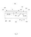
- Fig. 1 shows a fiber optic sensor 20 having a first optical fiber 21 and a second optical fiber 22 according to an embodiment.
- the two light guides 21, 22 are typically cylindrically symmetric and typically have a fiber core and a cladding surrounding the fiber core. For reasons of clarity, the transition from the fiber core to the shell is not shown.
- the fiber-optic sensor 20 comprises a body 201 having a cavity 202. An end 211 of the first light guide 21 is arranged in the cavity 202 at least with the end face 213 extending to the fiber axis 215 at an angle of approximately 45 °, as in the schematic central cross-sectional view along the fiber axis 215 in FIG Fig. 1 will be shown.
- a second optical waveguide 22 with its end piece 221 is arranged so that it can vibrate in the cavity 202.
- the end piece 221 has an axis of rotation 225 at an angle of approximately 45 ° extending end face 213.
- the two end pieces 211 and 221 coaxial with each other and the two end faces 213 and 223 are arranged substantially parallel to each other.
- the end piece 221 is connected to the body 201 so that it can perform bending vibrations in the plane shown.
- the second end piece 221 can be set in bending oscillations.
- a minimum distance d between the two end faces 213, 223 is modulated. Accordingly, the light transmission characteristics between the first optical fiber 21 and the second optical fiber 22 are modulated so that an amplitude and / or a frequency of the bending vibration are determined by measuring the light transmission characteristics, eg, the light power or amount of light transported by the fiber optic sensor 20 can. This makes it possible to sensitively detect and / or even quantify sound events. For the quantification of sound events typically calibration measurements are used.
- the effective length L 2 of the end piece 221 can also be used to set the fundamental frequency or natural frequency of the bending vibrations of the end piece 221, the natural frequency being inversely proportional to the square of the effective length L 2 .
- the natural frequency of the bending vibrations for a standard fiber having a total diameter of 125 ⁇ m and a 9 ⁇ m thick fiber core as the optical waveguide 21 at an effective length L 2 of the end piece 221 of 2 mm is about 24 kHz. If the sensor body 201 is subjected to a sound signal containing the natural frequency of the bending vibrations of the end piece 221, the end piece 221 can be excited to resonant oscillations. Such a sound signal can therefore be detected particularly sensitive.
- tail 221 may also be excited to harmonics if the sound signal includes a corresponding frequency component. Since the harmonics are typically nonharmonic, it may be possible to deduce from the frequency of the bending vibration also a sound frequency in the sound signal. For this purpose, appropriate calibration measurements are taken into account, which typically also take into account that the bending vibration of the end piece 221 may be limited by the end piece 211 in one direction.
- the length L 1 of the end piece 211 of the first light guide 21 is typically substantially smaller than the length L 2 of the end piece 221 of the second light guide 22, so that the end piece 211 has a much higher natural frequency.
- the length L 1 of the end piece 211 may be only 1/10 or less of the length L 2 . Accordingly, the natural frequency of the end piece 211 will be at least 100 times the natural frequency of the end piece 221 and thus, for example, outside an expected sound frequency. This simplifies the signal evaluation.
- the end piece 221 is dimensioned so that it is also capable of resonant bending vibrations in an expected frequency range of a sound event.
- two sound frequencies can be detected in parallel with a fiber optic sensor 20.
- the two end pieces 211, 221 are fixedly connected to body 201 via respective annular connectors 205, 206, e.g. glued with an epoxy resin.
- the connecting elements 205, 206 may also be formed by a corresponding Epoxydharz Archives.
- the two end pieces 211, 221 in the rest position have a minimum distance d, which is smaller than a wavelength that can be used for measurements of the light transmission properties between the first light guide 21 and the second light guide 22.
- a minimum distance d which is smaller than a wavelength that can be used for measurements of the light transmission properties between the first light guide 21 and the second light guide 22.
- the two end pieces 211, 221 are arranged in the cavity of a glass capillary 203, for example a glass capillary with a circular cross section, or a glass cuvette 203 of the body 201. If during a bending vibration of the end piece 221, the minimum distance d is greater than the wavelength, then one in the first Optical fiber 21 from the left incoming light signal at the end face 223 totally reflected, reflected from the inner surface of the glass capillary 203 or the glass cuvette 203 again and goes back from there the first light guide 21. This is in Fig. 1 represented by the arrow 28.
- the area between the end face 223 and the inner surface acts as a so-called cavity, the mirror of which can be considered as light guides 21, 22 as 4% reflecting mirror when using glass fibers.
- the light signal returning in the second optical fiber 22 is modulated as a function of the distance r between the face 223 and the inner surface. By means of a measurement of the light signal returning in the second light guide 22, it is therefore also possible to detect extremely sensitive bending vibrations with amplitudes above the wavelength of the light, typically in the ⁇ m range.
- Fig. 2 shows a fiber optic sensor 30 in a schematic cross section along the fiber axes 215, 225 of the light guides 21, 22 in the rest position according to another embodiment.
- the fiber optic sensor 30 is constructed similarly to the fiber optic sensor 20.
- the end faces 213, 223 of the two light guides 21, 22 are not quite planar. Rather, the end faces 213, 223 have a convex surface whose radius of curvature, however, is large compared to the diameter of the light guides 21, 22.
- Such a surface curvature can be generated, for example, by a polishing process of the end faces 213, 223.
- the middle tangents to the end faces 213, 223 and the respective fiber axis 215, 225 each form an angle of about 45 °.
- the fiber axis 225 and the tangents to the end surface 223 typically form a total reflection angle for light that can be transported along the fiber axis 225.
- the end faces 213, 223 of the two light guides 21, 22 touch each other in the rest position with their respective fiber cores. Due to the curved surfaces of the end faces 213, 223, the contact surface is very small.
- the cohesive forces between the end pieces 211, 221 are reduced compared to embodiments with in the rest position contacting flat end faces 213, 223.
- the end piece 221 of the second optical waveguide 22 can be more easily put into resonant oscillations, which enables very sensitive sound detection.
- the fiber cores of the two light guides 21, 22 of the fiber optic sensor 30 may, however, in the rest position also have a distance to one another that is smaller than a wavelength that can be used for measurements of the light transmission properties between the first light guide 21 and the second light guide 22.
- only one of the end faces 213, 223 is formed as a convex surface, while the other of the two end faces 213, 223 is formed by a plane. Also in this embodiment, the two end surfaces 213, 223 can touch in the rest position with a very small contact surface.
- the end piece 221 of the second fiber optic sensor 22 is supported in the body 201, which typically comprises a glass capillary having a round cross-section, so that it can perform bending vibrations in a plane substantially perpendicular to the in-plane Fig. 2 shown section plane is. Also in this embodiment, both bending oscillations of small amplitudes, typically in the nm range, as well as bending vibrations with amplitudes above the wavelength of light, typically in the micron range, can be detected extremely sensitive.
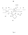
- FIG 3 shows a schematic representation of a measuring device 60 according to an embodiment.
- the measuring device 60 comprises a fiber-optic sensor 20, 30 as described with reference to FIGS FIGS. 1 and 2 was explained.
- the measuring device 60 comprises a first photodetector 61, which is connected to the first optical waveguide 21 of the optical fiber sensor 20, 30 and is adapted to perform a measurement on a light signal 611 transported by the first optical waveguide 21.
- the second optical fiber 22 of the fiber optic sensor 20, 30 is optically coupled via an optical coupler 63, such as a 3 dB coupler, to both a light source 64, typically a laser, and a second photodetector 62.
- an optical coupler 63 such as a 3 dB coupler
- the light source 64 feeds a light signal during the measurement 641 via a light guide 24 in the optical coupler 63, which at least partially feeds the light signal 641 as a light signal 631 in the second light guide 22.
- a part of the light signal 631 can be coupled as light signal 611 into the first light guide 21 and measured by the connected first photodetector 61.
- a further part of the light signal 631 can be fed back as a light signal 622 into the second light guide 22 and then fed via the optical coupler 63 and a light guide 23 as a light signal 621 to a second photodetector 62 for measurement .
- the light signal 621 may contain both portions of the returning light signal 633 and portions of the original light signal 641 fed by the light source 64.
- measurements of the second photodetector 62 can be used to calculate the returning light signal 633 and thus determine the state-dependent optical transmission properties of the fiber-optic sensor 20, 30.
- the end piece 221 of the fiber optic sensor 20, 30 is e.g. By a sound event in oscillation, this leads to a modulation of the optical transmission properties of the fiber optic sensor 20, 30.
- the first photodetector 61 and / or the second photodetector 62 can thus a sensitive detection and / or quantification of the sound event are provided.
- the first photodetector 61 and the second photodetector 62 are each typically a photodiode that is responsive to a wavelength range of the light signal 641 of the light source 64, e.g. tuned to about 800 nm to 1500 nm.
- the first photodetector 61 and the second photodetector 62 are also typically identical.
- optical fiber sensor 20, 30 may also be optically connected to the other components of the measuring device 60, that the light signal 631 is fed from the optical coupler 63 during the measurement in the first light guide 21, and the measurement of the in the second: optical fiber 22 transmitted light signal 611 by means of the first photodetector 61 takes place.
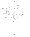
- Fig. 4 illustrates in a schematic representation of a measurement of the measuring device 60 from Fig. 3 according to an embodiment.
- the optical transmission characteristics of the fiber optic sensor 20, 30 do not change.
- unmodulated light signals 611 and 621 can be measured on the first photodetector 61 and possibly on the second photodetector 61 when a light signal 641 of the light source 64 is emitted.
- a constant light signal 641 can be emitted by the light source 64, which typically leads to time-constant light signals 611, 621 without external mechanical excitation of the fiber-optic sensor 20, 30.
- From non-modulated light signals 611 and / or 621 can therefore be closed to a located in its rest position end piece 221 of the second light guide 22. This means for a sound measurement that no detectable sound event has occurred.
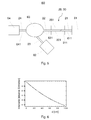
- Fig. 5 illustrates in a schematic representation of a further measurement of the measuring device 60 from Fig. 3 according to an embodiment.
- the end piece 221 of the second optical waveguide 22 is set into small amplitude oscillations by an external mechanical excitation, for example by a sound pulse impinging on the body 201 of the fiber optic sensor 20, 30, the light evanescently coupling into the first optical waveguide 21 will be modulated. From the modulated light power and / or light quantity 611 measured at the first photodetector 61, the oscillation amplitude and / or oscillation frequency of the end piece 221 can be determined. As a result, a sound event can be sensitively detected and / or quantified. This will be in Fig. 6 exemplified clarified.
- Fig. 6 shows an exemplary measurement curve, as during a measurement according to Fig. 5 can be obtained at the first photodetector 61.
- the intensity measurable by the first photodetector 61 during the oscillation of the end piece 221 depends, as in FIG Fig. 6 shown curve, from the distance d of the two end pieces 211, 221 from, wherein in Fig. 6 the rest position with mutually contacting end pieces 211, 221 corresponds to a relative intensity value 1.
- the relative light intensity measurable at the first photodetector 61 decreases accordingly.
- integral measurements over one or more periods of the expected resonant frequency of the tail 221 may be used to detect and quantify a sound signal. The higher the measured relative averaged relative intensity at the first photodetector 61, the lower the oscillation amplitudes of the end piece 221 and the weaker the sound signal impinging on the fiber optic sensor 20, 30.
- the location of the sound source must also be determined. This can e.g. by using four suitably positioned fiber optic sensors 20, 30.
- the location of a partial discharge in an insulation can typically be determined much more accurately by measuring the sound events emanating from the partial discharge with the fiber optic sensors 20, 30 than by electromagnetic measurements, since the speed of sound in the insulation is several orders of magnitude lower than the propagation velocity of electromagnetic fields in the insulation is.
- Figure 7 illustrates in a schematic representation of yet another measurement of the measuring device 60 from Fig. 3 according to an embodiment. If the distance d of the two end pieces 211, 221 during the oscillation of the end piece 221 is greater than the wavelength of the input light signal 641, no light from the first photodetector 61 can be detected in the associated time interval. At the same time, however, the light signal 633 reflected back into the second optical waveguide 22 typically increases. By measuring the light signal component 621 of the light signal 633 fed into the optical fiber 23 via the optical coupler 62, it is thus also possible to determine oscillation amplitudes of vibrations of the tail 221 that are greater than those of FIG Wavelength of the input light signal 641 are. As already related to Fig.
- a Fabry-Perot cavity 632 is formed between the end face 223 and the inner surface of the body 201 such that the light signal 633 intersperses as a function of the distance r corresponding to the length of the arrow 632 representing the Fabry-Perot cavity the end face 223 and the inner surface is modulated.
- FIG. 8 an exemplary measurement curve, as during a measurement according to Fig. 7 can be recovered by means of the second photodetector 62.
- the relative intensity shown by way of example corresponds to a half period of a vibration with an amplitude of approximately 10 ⁇ m.
- a plurality of maxima and minima of the relative intensity at the second photodetector 62 can be measured. From the number of measured minima and / or maxima of the measured at the second photodetector 62 relative intensity or from the complete curve can be concluded directly on the amplitude of vibration of the tail 221 and thus at least the relative strength of the vibration exciting sound event.
- the measuring device 60 can thus detect and / or quantify mean or stronger sound events via measurements of the light power and / or quantity of light exchanged evanescently between the second light guide 22 and the first light guide 21 as well as measurements of the light component backscattered in the second light guide 22.
- the measuring device 60 can typically also detect and / or quantify mean or stronger sound events via measurements of the evanescently between the second light guide 22 and the first light guide 21, since during each oscillation of the end piece 221 at least short-term evanescent light transmissions between the second light guide 22 and the second first light guide 21 occur.
- the measuring device 60 or the fiber optic sensors 20, 30 can be used for the detection of sound events, in particular for the detection of sound events in partially discharge-prone isolations of high-voltage equipment, which will be explained below for high-voltage equipment.
- Fig. 9 shows a high-voltage fitting 100 for receiving a high-voltage cable 1 according to an embodiment in a schematic central cross-sectional view along the cylinder axis of the high voltage cable 1.
- the rotationally symmetrical high voltage cable 1 inside a conductor 11 for conducting high current, for example.
- An aluminum or copper conductor, of a Cable insulation 12, typically a VPE insulation (cross-linked polyethylene), and an outer cable shield 13, for example, an outer conductive layer or a semiconductive outer cable shield is surrounded.
- the high-voltage cable 1 may additionally have cushioning layers and a copper screen and an outer jacket for protection against environmental influences. This may be a polyethylene jacket or a jacket of another halogen-free material.
- the high voltage cable 1 may have an inner conductive layer between the conductor 11 and the XLPE insulation. This inner conductive layer is also not shown.
- the cable end closure 100 represents a cable end 100, as used for example in overhead lines.
- the cable end closure 100 has a housing 110, for example a ceramic housing, which closes off the inner parts of the high voltage fitting 1 from the environment.
- a housing 110 for example a ceramic housing
- an insulating region 2 is arranged in the interior of the housing.
- the insulating region 2 can be formed, for example, by an insulating space filled with oil or gas.
- the insulating region 2 forms a substantially cylindrically symmetrical area.
- the outer layers are removed, the typically semiconductive outer cable shield 13 continues into the area of the field control part and thereafter only the cable insulation 12 through the end closure to the head fitting the conductor 11 is continued axially. Only the conductor 11 is completely passed through the cable end 100 to be in the right area of FIG. 1 after leaving the cable end 100 to be connected to the overhead line. Inside the cable end closure 100, the conductor 11 is surrounded directly by the insulating area 2 only in the area of the removed cable insulation.
- a rotationally symmetrical electrically insulating field control part 3 is used in the isolation area 2, which occupies those space within the isolation area 2, in which the electric field strength would be too large for the insulating materials in the isolation area 2.
- the field control part 3 has an inner hollow cylinder into which the high voltage cable 1 can be inserted.
- the field control part 3 may be designed as a field control cone.
- the field control member 3 is an elastomeric field control member made of an elastomeric body, eg, a silicone elastomer body.
- the inner hollow cylinder is typically dimensioned such that between the cable insulation 12 of the inserted cable 1 and the field control part 3 a Press fit is present and the field control part 3 thus forms a stress cone.
- the isolation area 2 and the field control part 3 together form the insulation 2, 3 of the cable end closure 100.
- the field control part 3 and / or the high voltage cable 1 can additionally be fixed, for example by means of springs, to the housing 110 or in a grounded area 5 of the insulation area 2, e.g. when the isolation region 2 is formed by a solid insulating body.
- Such a fixation of field control part 3 and / or high voltage cable 1 is typically used in a construction of the cable end closure 100 in component construction.
- the structure of the cable end closure 100 may also be designed according to the winding technique or Aufschiebetechnik.
- the insulation regardless of the design used, a field control part 3 for receiving the cable 1 with partially removed cable insulation 12 and the appropriate management of the field lines in high voltage operation.
- an elastomeric field control part 3 is used, in which a suitably shaped conductive deflector 4 is integrated.
- the conductive deflector 4 is in electrical contact with the cable shield 13.
- the conductive deflector 4 is also made of a silicone elastomer, but has a suitable electrical conductivity by doping. Due to material inhomogeneities or defects, there are typically areas of increased field strength. These are in Fig. 9 represented by the dashed rimmed areas 8. The probability of the occurrence or onset of partial discharges is increased in the areas 8 with increased field strength.
- a fiber optic sensor 20, 30 is arranged, as with respect to FIGS FIGS. 1 and 2 was explained.
- the fiber optic sensor 20, 30 is completely embedded with its body 201 in the field control part 3, which surrounds the cable insulation 12 of the high voltage cable 1 and thus the conductor 11 in.
- the field control part 3 thus represents at least a part of an insulation of the high voltage set 100. Due to the mechanical coupling between the fiber optic sensor 20, 30 and the insulation, sound events in the field control part 3, ie in the insulation can detect.
- the fiber optic sensor 20, 30 is adapted to at least one sound frequency characteristic of partial discharges.
- the tail of the second optical fiber may be configured to have a resonant frequency for flexural vibrations in the range of about 10 kHz to about 100 kHz.
- the other components are with respect to the FIGS. 3 to 8 explained measuring device for measuring the sound events in an evaluation and control unit 70.
- the evaluation and control unit 70 is typically outside the high voltage 100 or at ground potential cable near area 5 of the isolation area. 2
- one or more optical supply fibers 50 can also be used to supply and remove optical measuring or test signals directly to the passive fiber-optic sensor 20, 30.
- the signals of the light source can be supplied via one of the optical supply fibers 50.
- the light source may also be a semiconductor laser integrated in the evaluation and control unit 70.
- the measurement results of the photodetectors or the measurement signals can be forwarded via one or more of the optical supply fibers 50 in a central monitoring point, so that expensive measurement campaigns can be omitted on site. Due to the low fiber attenuation even fiber optic measurements from a central monitoring point over long distances are possible.
- the fiber optic sensor 20, 30 can detect very sensitive mechanical vibrations in adjacent media and in particular sound events.
- the fiber optic sensor 20, 30 is typically designed so that it consists only of dielectric materials, such as glass or polymer material, and therefore the electric field distribution in the cable end closure 100 is not or only slightly changed.
- the fiber optic sensor 20, 30 is practically not affected by external electromagnetic fields. Therefore, the fiber optic sensor 20, 30 can also be positioned in the vicinity of regions 8 with a particularly high field strength, and therefore in the vicinity of risk areas, for the detection of partial discharges. This can be a sensitive monitoring of partial discharges during operation, ie High voltage conditions are ensured. This increases the safety of the operation of high voltage equipment.
- the shape and / or conductivity of the conductive deflector 4 may be modified so as to compensate for the change in the electric field resulting from the fiber optic sensor 20 and / or the supply optical fibers 50.
- the fiber-optic sensor 20, 30 mechanically coupled to the insulation enables a more sensitive detection vibration of the insulation and thus an earlier detection of partial discharges.
- the body 201 of the fiber optic sensor 20, 30 it is also possible to embed the body 201 of the fiber optic sensor 20, 30 only partially in the typically elastomeric field control part 3, as illustrated in the fully embossed body 201 of the fiber optic sensor 20, 30.
- the arrangement of the fiber optic sensor 20, 30 within the high voltage set 100 also protects this from external influences, so that reliable and low-maintenance sensors for partial discharges can be provided.
- a plurality of fiber optic sensors 20, 30 are mechanically coupled to the insulation 2, 3.
- the measurement accuracy can be further increased and / or a more accurate localization of a partial discharge phenomenon in the insulation 2, 3 are made.
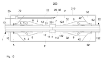
- Fig. 10 shows a high voltage set 200 for receiving two high voltage cables 1 and 22 according to an embodiment in a schematic central cross sectional view along the cylinder axes of the coaxially oriented high voltage cables 1 and 22.
- the rotationally symmetrical high voltage cables 1, 22 each comprise a conductor 11 and 112 for conducting high current and a the respective Conductor 11, 112 surrounding cable insulation 12, 122.
- the high voltage fitting 200 is a high voltage cable sleeve for connecting two high voltage cables.
- the cable sleeve 200 has a housing 210, such as a metal housing, in which the high voltage cables 1 and 22 are arranged centrally.
- the isolation region 2 of the cable sleeve 200 typically becomes formed by a cast resin insulator or a silicone body. Furthermore, the insulation and field control in the area of the connected metallic conductors 11, 112 to restore. This is done for example via a crimp connection and with a weakly conductive polymer ring 7, which are also embedded in the isolation area 2.
- the typically rotationally symmetrical insulation 2, 3, 32 of the cable sleeve 200 is formed by the field control parts 3, 23 and the insulating region 2.
- the isolation region 2 may be terminated by an unillustrated outer conductive sleeve coating disposed on the outer surface of the isolation region 2 with a small gap remaining to the housing 210 and being grounded together with the cable shields 13, 132.
- the field control parts 3, 32 are typically elastomeric field control parts 3, 32, in which a respective conductive deflector 4, 42 is integrated.
- the cable sleeve 200 may be embodied in component construction, in extrusion technology or in accordance with the winding technique or the slip-on technique. Thus, the insulation of the cable sleeve in component manner from a contiguous elastomeric field control part with integrated deflectors 4, 42 are made, the space of in Fig.
- the insulation comprises at least one field control part 3, 32 for receiving the cables 1, 22 with cable insulation 12, 122 removed at the respective cable ends and for suitable guidance of the field lines in high-voltage operation.
- a fiber optic sensor 20, 30 with its body 201, as described with reference to FIGS FIGS. 1 to 2 has been described, arranged in the insulating region 2 or embedded in the insulating region 2.
- the fiber optic sensor 20, 30 is also a sensor that has a vibration, in particular can sensitively detect a sound event. In this way, occurring partial discharges in the insulation 2, 3, 32 of the cable sleeve 200 and the cable insulation 12, 122 can be reliably detected via the sound emissions associated with partial discharges and easily monitored for longer periods during the high-voltage operation.
- the body 201 of the fiber-optic sensor 20, 30 also embedded in one of the two or both field control parts 3 and 32, or on a surface of one of the two field control parts 3 and 32 in the respective at-ground cable area 5, 52nd and may be arranged on the conductive sleeve coating and the plurality of fiber optic sensors 20, 30 may be mechanically coupled to the isolation area 2 and the two field control parts 3 and 32, respectively.
- the high-voltage device is a switchgear, eg a control cabinet.
- the high-voltage device may also be a generator, a voltage converter, eg an inverter or a transformer.
- a simple and sensitive detection and / or quantification of partial discharges in the insulation can be provided by means of a fiber-optic sensor mechanically coupled to the respective insulation.
- Such a construction can be used for detecting and / or quantifying and / or monitoring microacoustic events that can be caused by stress cracks in the rock or concrete, for example in mining or tunneling.
- a method for detecting partial discharges in an insulation of a high-voltage installation eg a high-voltage cable set, as described with reference to the Figures 9 and 10 described.
- the method comprises measuring a vibration-characterizing amount of insulation by means of a fiber-optic sensor as described with reference to FIGS FIGS. 1 and 2 which is mechanically coupled to the insulation.
- the method is carried out with a measuring arrangement as described with reference to the FIGS. 3 to 8 was explained.
- the measurement of a variable characterizing a vibration typically occurs in the current-carrying state of the high-voltage system during operation. This also allows a continuous or event dependent measurement of mechanical size, i. a monitoring of partial discharges during operation. As a result, the safety high-voltage system and / or a high-voltage network, whose insulation is monitored with integrated fiber optic sensors, can be significantly improved.
Landscapes
- Physics & Mathematics (AREA)
- General Physics & Mathematics (AREA)
- Engineering & Computer Science (AREA)
- Aviation & Aerospace Engineering (AREA)
- Acoustics & Sound (AREA)
- Chemical & Material Sciences (AREA)
- Analytical Chemistry (AREA)
- Electromagnetism (AREA)
- Investigating Or Analysing Materials By Optical Means (AREA)
- Measurement Of Mechanical Vibrations Or Ultrasonic Waves (AREA)
Applications Claiming Priority (1)
| Application Number | Priority Date | Filing Date | Title |
|---|---|---|---|
| DE102010061605A DE102010061605A1 (de) | 2010-12-28 | 2010-12-28 | Faseroptischer Sensor sowie Messeinrichtung mit einem faseroptischen Sensor |
Publications (1)
| Publication Number | Publication Date |
|---|---|
| EP2472275A2 true EP2472275A2 (fr) | 2012-07-04 |
Family
ID=45463226
Family Applications (1)
| Application Number | Title | Priority Date | Filing Date |
|---|---|---|---|
| EP11192367A Withdrawn EP2472275A2 (fr) | 2010-12-28 | 2011-12-07 | Capteur à fibres optiques et dispositif de mesure doté d'un capteur à fibres optiques |
Country Status (2)
| Country | Link |
|---|---|
| EP (1) | EP2472275A2 (fr) |
| DE (1) | DE102010061605A1 (fr) |
Cited By (4)
| Publication number | Priority date | Publication date | Assignee | Title |
|---|---|---|---|---|
| CN107942215A (zh) * | 2017-12-20 | 2018-04-20 | 哈尔滨理工大学 | 外置贴合式非本征法布里珀罗光纤传感器及测试平台 |
| CN112562237A (zh) * | 2020-12-11 | 2021-03-26 | 无锡科晟光子科技有限公司 | 一种应用于围栏上的光纤振动系统定位精度优化方法 |
| CN112912742A (zh) * | 2018-10-26 | 2021-06-04 | 泰科电子瑞侃有限责任公司 | 用于高压电缆附件的光学检测器和光学测量放电的方法 |
| CN115616361A (zh) * | 2022-11-03 | 2023-01-17 | 南京白云瑞来科技有限公司 | 一种基于光纤传感的全密封开关柜监测系统及方法 |
Families Citing this family (3)
| Publication number | Priority date | Publication date | Assignee | Title |
|---|---|---|---|---|
| DE102014116908A1 (de) * | 2014-11-19 | 2016-05-19 | Aiq Dienstleistungen Ug (Haftungsbeschränkt) | Faser ausgerichtet und in Bezug auf Bewegung gekoppelt mit einem elektrischem Kabel |
| DE102016125799B4 (de) | 2016-12-28 | 2021-11-11 | fos4X GmbH | Akustik-Emissionssensor |
| DE102018124210A1 (de) * | 2018-10-01 | 2020-04-02 | Hochschule Für Technik Und Wirtschaft Berlin | Verfahren zum Bestimmen eines Betriebszustands für ein elektrisches Betriebsmittel mit einem Schalterelement |
Family Cites Families (3)
| Publication number | Priority date | Publication date | Assignee | Title |
|---|---|---|---|---|
| DE19514852C2 (de) * | 1995-04-26 | 1997-07-03 | Deutsche Forsch Luft Raumfahrt | Verfahren und Anordnung zur Beschleunigungs- und Vibrationsmessung |
| US6300767B1 (en) * | 1998-11-30 | 2001-10-09 | General Electric Company | System and apparatus for predicting failure in insulated systems |
| US7168323B1 (en) * | 1999-09-28 | 2007-01-30 | Rockwell Automation Technologies, Inc. | System and method for optical vibration sensing |
-
2010
- 2010-12-28 DE DE102010061605A patent/DE102010061605A1/de not_active Ceased
-
2011
- 2011-12-07 EP EP11192367A patent/EP2472275A2/fr not_active Withdrawn
Non-Patent Citations (1)
| Title |
|---|
| None |
Cited By (4)
| Publication number | Priority date | Publication date | Assignee | Title |
|---|---|---|---|---|
| CN107942215A (zh) * | 2017-12-20 | 2018-04-20 | 哈尔滨理工大学 | 外置贴合式非本征法布里珀罗光纤传感器及测试平台 |
| CN112912742A (zh) * | 2018-10-26 | 2021-06-04 | 泰科电子瑞侃有限责任公司 | 用于高压电缆附件的光学检测器和光学测量放电的方法 |
| CN112562237A (zh) * | 2020-12-11 | 2021-03-26 | 无锡科晟光子科技有限公司 | 一种应用于围栏上的光纤振动系统定位精度优化方法 |
| CN115616361A (zh) * | 2022-11-03 | 2023-01-17 | 南京白云瑞来科技有限公司 | 一种基于光纤传感的全密封开关柜监测系统及方法 |
Also Published As
| Publication number | Publication date |
|---|---|
| DE102010061605A1 (de) | 2012-06-28 |
Similar Documents
| Publication | Publication Date | Title |
|---|---|---|
| EP2472688B1 (fr) | Installation à haute tension et procédé de surveillance de processus de vieillissement d'un isolant dans une installation à haute tension | |
| EP2472275A2 (fr) | Capteur à fibres optiques et dispositif de mesure doté d'un capteur à fibres optiques | |
| DE102010061606B4 (de) | Hochspannungsgarnitur und Verfahren zur Detektion von Teilentladungen in Hochspannungsgarnituren | |
| EP1240704B1 (fr) | Appareil de mesure optique situe dans une barre conductrice comprimee de machine electrique | |
| WO2016180396A1 (fr) | Garniture de câble haute tension et procédé de réalisation d'une garniture de câble haute tension | |
| DE102014116908A1 (de) | Faser ausgerichtet und in Bezug auf Bewegung gekoppelt mit einem elektrischem Kabel | |
| EP3109958A1 (fr) | Élement de commande de champ pour un accessoire de cable haute tension et procede de mesure optique de decharges partielles | |
| DE102011054047A1 (de) | System und Verfahren zur Überwachung von Elektromaschinenkomponenten | |
| EP2016373A2 (fr) | Procede et dispositif de mesure pour la mesure repartie dans l'espace et/ou à distance de grandeurs physiques | |
| DE3638345A1 (de) | Einrichtung und verwendung eines lichtwellenleiter-sensors fuer minimale dehnungen | |
| DE102015217430A1 (de) | Faseroptischer Beschleunigungssensor | |
| Bogachkov et al. | Detection of sections with slightly changed optical characteristics in fiber optical communication lines | |
| EP2466286A1 (fr) | Système de garde d'eau à fibres optiques | |
| DE102015101608B4 (de) | Verfahren zur Signalweiterleitung, Vorrichtung mit einer optischen Faser und Detektionssystem | |
| DE102013104155B4 (de) | Hochspannungseinrichtung mit einem faseroptischen Sensor und Verfahren zum Prüfen einer Isolierung einer derartigen Hochspannungseinrichtung | |
| EP3729032B1 (fr) | Connecteur électrique comprenant un capteur de température | |
| AT513732A1 (de) | Verfahren zur ortsaufgelösten Druckmessung | |
| DE102020119012B4 (de) | Vorrichtung und Verfahren zum Bestimmen einer Ladungsstärke einer Teilentladung | |
| DE102018130261A1 (de) | Verfahren zur faseroptischen Temperaturmessung in einem als Hohlfaser ausgebildeten Lichtwellenleiter, Temperatursensor, Kühlsystem und Ladesystem | |
| DE60009758T2 (de) | Optischer Zeitbereichreflektometer für optische multi-mode Fasern, Lichtquelleabschnitt dafür und Verfahren zur Herstellung dieses Lichtquellenabschnitts | |
| DE19725431A1 (de) | Verfahren, Verwendung und Vorrichtung zur Bestimmung der Lage einer unterirdisch verlegten Rohrleitung o. dgl. | |
| KR102768771B1 (ko) | 자외선 감지용 광섬유 격자 센서 모듈 및 이의 제조방법 | |
| EP3644074A1 (fr) | Détecteur optique pour accessoire de câble haute tension et procédé de mesure optique de décharges électriques | |
| DE4313138C2 (de) | Meßnormal für optische Dämpfungsmessungen | |
| DE10242205B4 (de) | Verfahren und Vorrichtung zur räumlich ausgedehnten Erfassung von Betriebszuständen |
Legal Events
| Date | Code | Title | Description |
|---|---|---|---|
| AK | Designated contracting states |
Kind code of ref document: A2 Designated state(s): AL AT BE BG CH CY CZ DE DK EE ES FI FR GB GR HR HU IE IS IT LI LT LU LV MC MK MT NL NO PL PT RO RS SE SI SK SM TR |
|
| AX | Request for extension of the european patent |
Extension state: BA ME |
|
| PUAI | Public reference made under article 153(3) epc to a published international application that has entered the european phase |
Free format text: ORIGINAL CODE: 0009012 |
|
| STAA | Information on the status of an ep patent application or granted ep patent |
Free format text: STATUS: THE APPLICATION IS DEEMED TO BE WITHDRAWN |
|
| 18D | Application deemed to be withdrawn |
Effective date: 20140701 |