EP2472204A2 - Control apparatus and refrigerating apparatus - Google Patents
Control apparatus and refrigerating apparatus Download PDFInfo
- Publication number
- EP2472204A2 EP2472204A2 EP11195887A EP11195887A EP2472204A2 EP 2472204 A2 EP2472204 A2 EP 2472204A2 EP 11195887 A EP11195887 A EP 11195887A EP 11195887 A EP11195887 A EP 11195887A EP 2472204 A2 EP2472204 A2 EP 2472204A2
- Authority
- EP
- European Patent Office
- Prior art keywords
- circuit breaker
- power supply
- compressor
- current
- voltage
- Prior art date
- Legal status (The legal status is an assumption and is not a legal conclusion. Google has not performed a legal analysis and makes no representation as to the accuracy of the status listed.)
- Withdrawn
Links
Images


Classifications
-
- F—MECHANICAL ENGINEERING; LIGHTING; HEATING; WEAPONS; BLASTING
- F25—REFRIGERATION OR COOLING; COMBINED HEATING AND REFRIGERATION SYSTEMS; HEAT PUMP SYSTEMS; MANUFACTURE OR STORAGE OF ICE; LIQUEFACTION SOLIDIFICATION OF GASES
- F25B—REFRIGERATION MACHINES, PLANTS OR SYSTEMS; COMBINED HEATING AND REFRIGERATION SYSTEMS; HEAT PUMP SYSTEMS
- F25B49/00—Arrangement or mounting of control or safety devices
- F25B49/02—Arrangement or mounting of control or safety devices for compression type machines, plants or systems
- F25B49/025—Motor control arrangements
-
- F—MECHANICAL ENGINEERING; LIGHTING; HEATING; WEAPONS; BLASTING
- F25—REFRIGERATION OR COOLING; COMBINED HEATING AND REFRIGERATION SYSTEMS; HEAT PUMP SYSTEMS; MANUFACTURE OR STORAGE OF ICE; LIQUEFACTION SOLIDIFICATION OF GASES
- F25D—REFRIGERATORS; COLD ROOMS; ICE-BOXES; COOLING OR FREEZING APPARATUS NOT OTHERWISE PROVIDED FOR
- F25D29/00—Arrangement or mounting of control or safety devices
-
- F—MECHANICAL ENGINEERING; LIGHTING; HEATING; WEAPONS; BLASTING
- F25—REFRIGERATION OR COOLING; COMBINED HEATING AND REFRIGERATION SYSTEMS; HEAT PUMP SYSTEMS; MANUFACTURE OR STORAGE OF ICE; LIQUEFACTION SOLIDIFICATION OF GASES
- F25B—REFRIGERATION MACHINES, PLANTS OR SYSTEMS; COMBINED HEATING AND REFRIGERATION SYSTEMS; HEAT PUMP SYSTEMS
- F25B49/00—Arrangement or mounting of control or safety devices
- F25B49/02—Arrangement or mounting of control or safety devices for compression type machines, plants or systems
-
- F—MECHANICAL ENGINEERING; LIGHTING; HEATING; WEAPONS; BLASTING
- F25—REFRIGERATION OR COOLING; COMBINED HEATING AND REFRIGERATION SYSTEMS; HEAT PUMP SYSTEMS; MANUFACTURE OR STORAGE OF ICE; LIQUEFACTION SOLIDIFICATION OF GASES
- F25B—REFRIGERATION MACHINES, PLANTS OR SYSTEMS; COMBINED HEATING AND REFRIGERATION SYSTEMS; HEAT PUMP SYSTEMS
- F25B2700/00—Sensing or detecting of parameters; Sensors therefor
- F25B2700/15—Power, e.g. by voltage or current
- F25B2700/151—Power, e.g. by voltage or current of the compressor motor
Definitions
- the present invention relates to a control apparatus and a refrigerating apparatus.
- a compressor provided in a refrigerating apparatus may lock due to some abnormalities such as overheating and a slow leak of a refrigerant.
- a common refrigerating apparatus includes a protection circuit (e.g., overload relay of bimetal, etc.) to protect the compressor against overcurrent or overheating. It is desirable that the abnormality causing locking of the compressor is resolved within a short time, but if the abnormality continues for a long time, the protection circuit is turned on and off repeatedly, possibly resulting in welding of the bimetal in the worst case.
- a circuit breaker that protects a system as a whole is operated.
- an individual circuit breaker is further provided, in series with the overload relay, for each of the two freezing circuits.
- Such an individual circuit breaker is realized by employing a manual-reset-type circuit breaker so as to prevent re-welding, as well as by being set such that the circuit breaker is operated before a main circuit breaker, which protects the whole system, is operated.
- a control apparatus configured to control a refrigerating apparatus including a compressor and a first circuit breaker, the first circuit breaker configured to interrupt a current flowing through the compressor when the current becomes greater than a predetermined current and configured to be closed in response to an operation by a user, the current flowing from a power supply through the compressor to cause the compressor to work
- the control apparatus includes: a voltage measuring unit configured to measure a voltage of the power supply; and a control unit configured to trip a second circuit breaker disposed in series with the first circuit breaker so that the current from the power supply flowing through the compressor is interrupted, when the measured voltage of the power supply becomes lower than a predetermined voltage, and close the second circuit breaker after the voltage of the power supply becomes higher than the predetermined voltage, the predetermined current corresponding to a current greater than the current flowing through the compressor when the voltage of the power supply is equal to the predetermined voltage.
- Fig. 1 depicts a configuration of a refrigerating apparatus 10 according to an embodiment of the present invention.
- the refrigerating apparatus 10 includes a freezer 20, refrigerant circuits 21 and 22, a commercial power supply 23, a breaking device 24, a transformer 25, and a control apparatus 26.
- the freezer 20 stores frozen items, body tissues, etc., at an ultralow temperature of -80°C, for example.
- the freezer 20 includes a temperature sensor 30 configured to output a voltage corresponding to a temperature inside the freezer.
- the refrigerant circuit 21 is a circuit configured to cool an inside of the freezer 20, and includes a compressor 40, a condenser 41, an expansion valve 42, and an evaporator 43.
- the compressor 40 (first compressor) is configured to suck refrigerant evaporated by the evaporator 43, and thereafter compress the refrigerant to be discharged to the condenser 41.
- the compressor 40 includes a motor (not shown) configured to cause the compressor 40 to work when supplied with power.
- the condenser 41 is configured to cool and liquefy the high-temperature, high-pressure, gaseous refrigerant compressed by the compressor 40.
- the expansion valve 42 is configured to gasify the high-pressure refrigerant liquefied by the condenser 41 and output the gasified refrigerant to the evaporator 43.
- the evaporator 43 is configured to evaporate the refrigerant to cool the inside of the freezer 20.
- the refrigerant circuit 22 is a circuit configured to cool the inside of the freezer 20, and includes a compressor 45 (second compressor), a condenser 46, an expansion valve 47, and an evaporator 48. Since blocks of the refrigerant circuit 22 is the same as those of the refrigerant circuit 21, detailed description thereof is omitted.
- the commercial power supply 23 is a power supply to supply power to the refrigerating apparatus 10, and is connected to an outlet (not shown) of the commercial power supply 23. It should be noted that the commercial power supply 23 is supplied to the control apparatus 26 as well, which is omitted in Fig. 1 .
- the breaking device 24 is configured to interrupt the current supplied from the commercial power supply 23 to the compressors 40 and 45 to cause the compressors 40 and 45 to stop working when the temperature inside the freezer 20 has reached a predetermined temperature or an overcurrent occurs in the compressors 40 and 45, for example.
- the breaking device 24 is provided between the commercial power supply 23 and the compressors 40 and 45, and includes circuit breakers 50 and 52 to 55 and cables 60 and 61.
- the circuit breaker 50 is a main circuit breaker and is configured to interrupt the current supplied to the compressors 40 and 45 when the current supplied from the commercial power supply 23 to the compressors 40 and 45 reaches an overcurrent level.
- a power supply voltage is applied to the compressor 40 via the cable 60 and the circuit breaker 54 and the cable 61 and the circuit breaker 52, as well as is applied to the compressor 45 via the cable 60 and the circuit breaker 55 and the cable 61 and the circuit breaker 53.
- circuit breaker 50 is tripped when the current flowing through the circuit breaker 50 has reached a predetermined current I0.
- the circuit breaker 52 (first circuit breaker) is a circuit breaker configured to protect the compressor 40 against an overcurrent, and interrupt a current IA flowing through the compressor 40 when the current IA has reached a predetermined current I1 (first current) indicative of an overcurrent.
- the predetermined current I1 is set to be smaller than (e.g., a half of) the predetermined current I0.
- the circuit breaker 53 (second circuit breaker) is a circuit breaker configured to protect the compressor 45 against an overcurrent, and interrupt a current IB flowing to the compressor 45 when the current IB has reached the predetermined current I1 (second current) indicative of an overcurrent.
- the circuit breakers 50 and 52 to 53 are manual-reset-type circuit breakers each configured to be reset by an operation by a user after having been activated.
- the circuit breaker 54 (third circuit breaker) is a so-called temperature control relay to be operated by the control apparatus 26, and is configured to be tripped by the control apparatus 26 when the temperature inside the freezer 20 has reached a predetermined temperature or a power supply voltage Vac becomes lower than a predetermined voltage V1 (e.g., 70% of the power supply voltage Vac).
- the circuit breaker 55 (fourth circuit breaker) is the so-called temperature control relay to be operated by the control apparatus 26, and is configured to be tripped by the control apparatus 26 when the temperature inside the freezer 20 has reached the predetermined temperature or the power supply Voltage Vac becomes lower than the predetermined voltage V1.
- the predetermined voltage V1 is determined such that the currents IA and IB when the power supply voltage Vac reaches the predetermined voltage V1 are smaller than the predetermined current I1 indicative of an overcurrent.
- each of the currents IA and IB when the power supply voltage Vac becomes the predetermined voltage V1 is referred to as a current I2 ( ⁇ I1).
- the transformer 25 is a so-called measuring transformer configured to step down the power supply voltage Vac with a predetermined rate.
- the control apparatus 26 is an apparatus configured to control the operation of the refrigerating apparatus 10 in an integral manner based on outputs from the transformer 25 and the temperature sensor 30, and includes an operation unit 80, a memory device 81, a display unit 82, and a microcomputer 83.
- the operation unit 80 is an operation panel, etc., for setting the operation of the refrigerating apparatus 10 by a user. Results of the operation in the operation unit 80 are sent to the microcomputer 83, for example.
- the memory device 81 is configured to store program data to be executed by the microcomputer 83 and other various data.
- the display unit 82 is a display panel, etc., for displaying various information such as the temperature inside the freezer 20, results of operation, presence/absence of abnormality in the refrigerating apparatus 10.
- the microcomputer 83 is configured to realize various functions by executing the program data stored in the memory device 81. For example, when the temperature inside the freezer 20 is set by a user, the microcomputer 83 executes a program for bringing the temperature inside the freezer 20 to the set temperature, and controls the blocks in the refrigerating apparatus 10.
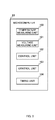
- the microcomputer 83 realizes functions of a temperature measuring unit 100, a voltage measuring unit 101, control units 102 and 103, and a timing unit 104 as illustrated in Fig. 2 , for example, when executing the program for bring the temperature inside the freezer 20 to the set temperature.
- the temperature measuring unit 100 is configured to measure the temperature inside the freezer 20 based on the output from the temperature sensor 30. Further, the temperature measuring unit 100 is configured to display the measured temperature on the display unit 82.
- the voltage measuring unit 101 is configured to measure the power supply voltage Vac based on the voltage transformed by the transformer 25. Since the power supply voltage Vac is an AC voltage, the voltage measuring unit 101 is configured to measure the effective value, for example, of the power supply voltage Vac.
- the control unit 102 is configured to control the circuit breakers 54 and 55 so that the measured temperature inside the freezer 20 reaches the set temperature.
- a predetermined temperature Ta e.g., -82°C
- the control unit 102 trip the circuit breakers 54 and 55 to cause the compressors 40 and 45 to stop working.
- the control unit 102 closes (connects) the circuit breakers 54 and 55 in a sequential manner to cause the compressors 40 and 45 to start working.
- Tb a predetermined temperature
- T1 a predetermined time
- the predetermined time T1 corresponds to a time for the pressure of a refrigerant on a suction side of the compressor 40 and the pressure of the refrigerant on a discharge side thereof to reach equilibrium (e.g., three minutes), for example.
- the predetermined temperature Ta corresponds to a first temperature
- the predetermined temperature Tb corresponds to a second temperature.
- the control unit 103 is configured to control the circuit breakers 54 and 55 based on the magnitude of the measured power supply voltage Vac and the predetermined voltage V1, namely, the magnitude of the effective value of the power supply voltage Vac and the effective value of the predetermined Voltage V1.
- the control unit 103 trips (i.e., turns off) the circuit breakers 54 and 55 to cause the compressors 40 and 45 to stop working.
- the control unit 103 closes the circuit breakers 54 and 55 in a sequential manner.
- control unit 103 causes the display unit 82 to display stop information indicating that the compressors 40 and 45 have stopped working due to a voltage drop.
- the timing unit 104 is configured to time with respect to the predetermined time T1 that is a time after the tripping of the circuit breakers 54 and 55 and a predetermined time T2 that is a time after the closing of the circuit breaker 54.
- the predetermined time T2 is the time (e.g., one minute) provided to avoid the concurrent activation of the compressors 40 and 45.
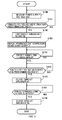
- the voltage measuring unit 101 acquires the output of the transformer 25 and measures the power supply voltage Vac (S100).
- the control unit 103 determines whether the power supply voltage Vac is lower than the predetermined voltage V1 (S101). If the power supply voltage Vac is higher than the predetermined voltage V1 (S101: NO), then processing S100 is repeated. On the other hand, if the power supply voltage Vac is lower than the predetermined voltage V1 (S101: YES), then the control unit 103 trips the circuit breakers 54 and 55 in order to prevent the currents IA and IB from reaching an overcurrent level in response to the drop in the power supply voltage Vac (S102). As a result, the currents IA and IB are interrupted and the compressors 40 and 45 stop working.
- the control unit 103 causes the display unit 82 to display the stop information indicating that the power supply voltage Vac has become lower than the predetermined voltage V1, thereby stopping the working of the compressors 40 and 45 (5103).
- the control unit 103 determines whether the predetermined time T1 has elapsed since the tripping of the circuit breakers 54 and 55 based on results of timing by the timing unit 104 (S104). If the predetermined time T1 has elapsed since the tripping of the circuit breakers 54 and 55 (S104: YES), then the control unit 103 determines whether the power supply voltage Vac is higher than the predetermined voltage V1 (S105). That is to say, at processing S105, the control unit 103 determines whether the power supply voltage Vac has recovered.
- control unit 103 determines that the power supply voltage Vac is higher than the predetermined voltage V1 (S105: YES), namely, if the control unit 103 determines that the power supply voltage Vac has recovered, then the control unit 103 closes the circuit breaker 54 to cause the compressor 40 to work (S106).
- the control unit 103 determines whether the predetermined time T2 has elapsed since the closing of the circuit breaker 54, based on the results of the timing by the timing unit 104 (S107). If the control unit 103 determines that the predetermined time T2 has elapsed since the closing of the circuit breaker 54 (S107: YES), then the control unit 103 closes the circuit breaker 55 to cause the compressor 45 to start working (S108).
- the compressors 40 and 45 resume working after the recovery of the power supply voltage Vac.
- the circuit breakers 54 and 55 are controlled only based on the temperature inside the freezer 20, namely, when the circuit breakers 54 and 55 are not tripped despite the drop in the power supply voltage Vac, the currents IA and IB continue to increase even after time t1 as illustrated by a dotted line. Then, at time t10, since the currents IA and IB reach the predetermined current I1 indicative of an overcurrent, the circuit breakers 52 and 53 are tripped.
- the circuit breakers 52 and 53 are so-called manual-reset-type circuit breakers, and in such a case, the compressors 40 and 45 will not restart working automatically after the recovery of the power supply voltage Vac.
- the compressors 40 and 45 restarts working after the recovery of the power supply voltage Vac, thereby being able to suppress an increase in the temperature inside the freezer 20.
- the control apparatus 26 trips the circuit breaker 54 (third circuit breaker) before the circuit breaker 52 (first circuit breaker) that interrupts an overcurrent is tripped.
- the circuit breaker 54 is closed.
- the manual-reset-type circuit breaker 52 is not tripped when the power supply voltage Vac drops, thereby being able to securely suppress an increase in the temperature inside the freezer 20.
- the control unit 103 does not close the circuit breaker 54 until a time when the predetermined time T1, corresponding to a time period from a time when the circuit breaker 54 is tripped to a time when the pressure of the refrigerant on the suction side of the compressor 40 and the pressure of the refrigerant on the discharge side thereof reach equilibrium, has elapsed.
- the load of the compressor 40 at startup can be reduced.
- the circuit breaker 54 is used also as a temperature-adjusting circuit breaker to adjust the temperature inside the freezer 20. Therefore, as compared with the case where the temperature-adjusting circuit breaker and the circuit breaker, that is tripped when the power supply voltage Vac drops, are provided separately, the number of components can be reduced.
- the display unit 82 displays the stop information indicating that the compressors 40 and 45 have stopped working, when the power supply voltage Vac drops below the predetermined voltage V1.
- a user can grasp that the compressors 40 and 45 have stopped due to the drop in the power supply voltage Vac. Even in the case where two compressors 40 and 45 are provided, as in the refrigerating apparatus 10, the increase in the temperature inside the freezer 20 can securely be suppressed.
- the compressor 45 is started up after the predetermined time T2 has elapsed since the startup of the compressor 40, thereby being able to reduce the transient current generated when the compressors 40 and 45 are started up.
- the refrigerating apparatus 10 is provided with two refrigerant circuits 21 and 22, however, a similar effect can be obtained even if only one refrigerant circuit (e.g., refrigerant circuit 21) is provided.
- the predetermined time T1 may be a predetermined multiple (e.g., 1.2 times) of an average time required for the pressure of the refrigerant on the suction side of the compressor 40 and the pressure of the refrigerant on the discharge side thereof to reach equilibrium.
- both of the currents interrupted by the circuit breakers 52 and 53 are the predetermined current I1, however, even if the currents interrupted by these circuit breakers are different, an effect similar to that in an embodiment of the present invention can be obtained as long as such currents are greater than the predetermined current I2.
Landscapes
- Engineering & Computer Science (AREA)
- Physics & Mathematics (AREA)
- Mechanical Engineering (AREA)
- Thermal Sciences (AREA)
- General Engineering & Computer Science (AREA)
- Chemical & Material Sciences (AREA)
- Combustion & Propulsion (AREA)
- Devices That Are Associated With Refrigeration Equipment (AREA)
- Air Conditioning Control Device (AREA)
Abstract
Description
- The present invention relates to a control apparatus and a refrigerating apparatus.
- A compressor provided in a refrigerating apparatus may lock due to some abnormalities such as overheating and a slow leak of a refrigerant. When the compressor locks an overcurrent flows, and if such a situation is left as it is, then a coil of the compressor motor burns out, leading to destruction of the compressor. Thus, a common refrigerating apparatus includes a protection circuit (e.g., overload relay of bimetal, etc.) to protect the compressor against overcurrent or overheating. It is desirable that the abnormality causing locking of the compressor is resolved within a short time, but if the abnormality continues for a long time, the protection circuit is turned on and off repeatedly, possibly resulting in welding of the bimetal in the worst case.
- On the other hand, in a so-called ultracold freezer configured to contain biotic samples and cool an inside of the freezer to a temperature lower than or equal to -80°C, if cooling capacity is lost due to problems such as locking of the compressor, precious biotic samples contained therein is damaged. Thus, there is one that is doubly provided with freezing circuits to prevent such an damage, so that even if one freezing circuit (e.g., compressor) fails, the other remaining freezing circuit will secure the cooling capacity, thereby avoiding the frozen samples from being thawed (Japanese Laid-Open Patent Publications Nos.
2006-68122 2010-65925 - If the locking of the compressor results in the welding of the bimetal, an overcurrent continues to flow, and therefore a circuit breaker (so-called breaker) that protects a system as a whole is operated. In the apparatus doubly provided with freezing circuits described above, in order to prevent the whole system from getting down due to the locking of the compressor in the one freezing circuit, an individual circuit breaker is further provided, in series with the overload relay, for each of the two freezing circuits. Such an individual circuit breaker is realized by employing a manual-reset-type circuit breaker so as to prevent re-welding, as well as by being set such that the circuit breaker is operated before a main circuit breaker, which protects the whole system, is operated.
- Incidentally, when a power supply voltage fluctuates, a voltage drop may cause the compressor to lock. An overcurrent flows in this case as well, however, if the individual circuit breaker of the manual-reset-type is operated at this moment, the freezing circuit remains at rest even after voltage recovery unless a user resets the circuit breaker, which prevents the initial freezing capacity from being used.
- A control apparatus according to an aspect of the present invention, which is configured to control a refrigerating apparatus including a compressor and a first circuit breaker, the first circuit breaker configured to interrupt a current flowing through the compressor when the current becomes greater than a predetermined current and configured to be closed in response to an operation by a user, the current flowing from a power supply through the compressor to cause the compressor to work, the control apparatus includes: a voltage measuring unit configured to measure a voltage of the power supply; and a control unit configured to trip a second circuit breaker disposed in series with the first circuit breaker so that the current from the power supply flowing through the compressor is interrupted, when the measured voltage of the power supply becomes lower than a predetermined voltage, and close the second circuit breaker after the voltage of the power supply becomes higher than the predetermined voltage, the predetermined current corresponding to a current greater than the current flowing through the compressor when the voltage of the power supply is equal to the predetermined voltage.
- Other features of the present invention will become apparent from descriptions of this specification and of the accompanying drawings.
- For more thorough understanding of the present invention and advantages thereof, the following description should be read in conjunction with the accompanying drawings, in which:
-
Fig. 1 is a diagram illustrating a configuration of a refrigeratingapparatus 10 according to an embodiment of the present invention; -
Fig. 2 is a diagram illustrating a functional block to be implemented by amicrocomputer 83; -
Fig. 3 is a flowchart illustrating an example of processing to be executed by amicrocomputer 83; and -
Fig. 4 is a diagram describing an operation of a refrigeratingapparatus 10 when a voltage Vac of a commercial power supply temporarily drops. - At least the following details will become apparent from descriptions of this specification and of the accompanying drawings.
-
Fig. 1 depicts a configuration of a refrigeratingapparatus 10 according to an embodiment of the present invention. The refrigeratingapparatus 10 includes afreezer 20,refrigerant circuits commercial power supply 23, a breakingdevice 24, atransformer 25, and acontrol apparatus 26. - The
freezer 20 stores frozen items, body tissues, etc., at an ultralow temperature of -80°C, for example. Thefreezer 20 includes atemperature sensor 30 configured to output a voltage corresponding to a temperature inside the freezer. - The
refrigerant circuit 21 is a circuit configured to cool an inside of thefreezer 20, and includes acompressor 40, acondenser 41, anexpansion valve 42, and anevaporator 43. - The compressor 40 (first compressor) is configured to suck refrigerant evaporated by the
evaporator 43, and thereafter compress the refrigerant to be discharged to thecondenser 41. Thecompressor 40 includes a motor (not shown) configured to cause thecompressor 40 to work when supplied with power. - The
condenser 41 is configured to cool and liquefy the high-temperature, high-pressure, gaseous refrigerant compressed by thecompressor 40. - The
expansion valve 42 is configured to gasify the high-pressure refrigerant liquefied by thecondenser 41 and output the gasified refrigerant to theevaporator 43. Theevaporator 43 is configured to evaporate the refrigerant to cool the inside of thefreezer 20. - Similarly to the
refrigerant circuit 21, therefrigerant circuit 22 is a circuit configured to cool the inside of thefreezer 20, and includes a compressor 45 (second compressor), acondenser 46, anexpansion valve 47, and anevaporator 48. Since blocks of therefrigerant circuit 22 is the same as those of therefrigerant circuit 21, detailed description thereof is omitted. - The
commercial power supply 23 is a power supply to supply power to the refrigeratingapparatus 10, and is connected to an outlet (not shown) of thecommercial power supply 23. It should be noted that thecommercial power supply 23 is supplied to thecontrol apparatus 26 as well, which is omitted inFig. 1 . - The
breaking device 24 is configured to interrupt the current supplied from thecommercial power supply 23 to thecompressors compressors freezer 20 has reached a predetermined temperature or an overcurrent occurs in thecompressors breaking device 24 is provided between thecommercial power supply 23 and thecompressors circuit breakers 50 and 52 to 55 andcables 60 and 61. - The
circuit breaker 50 is a main circuit breaker and is configured to interrupt the current supplied to thecompressors commercial power supply 23 to thecompressors - A power supply voltage is applied to the
compressor 40 via the cable 60 and thecircuit breaker 54 and thecable 61 and the circuit breaker 52, as well as is applied to thecompressor 45 via the cable 60 and thecircuit breaker 55 and thecable 61 and the circuit breaker 53. - It is assumed in an embodiment of the present invention that the
circuit breaker 50 is tripped when the current flowing through thecircuit breaker 50 has reached a predetermined current I0. - The circuit breaker 52 (first circuit breaker) is a circuit breaker configured to protect the
compressor 40 against an overcurrent, and interrupt a current IA flowing through thecompressor 40 when the current IA has reached a predetermined current I1 (first current) indicative of an overcurrent. The predetermined current I1 is set to be smaller than (e.g., a half of) the predetermined current I0. - The circuit breaker 53 (second circuit breaker) is a circuit breaker configured to protect the
compressor 45 against an overcurrent, and interrupt a current IB flowing to thecompressor 45 when the current IB has reached the predetermined current I1 (second current) indicative of an overcurrent. - The
circuit breakers 50 and 52 to 53 are manual-reset-type circuit breakers each configured to be reset by an operation by a user after having been activated. - The circuit breaker 54 (third circuit breaker) is a so-called temperature control relay to be operated by the
control apparatus 26, and is configured to be tripped by thecontrol apparatus 26 when the temperature inside thefreezer 20 has reached a predetermined temperature or a power supply voltage Vac becomes lower than a predetermined voltage V1 (e.g., 70% of the power supply voltage Vac). - The circuit breaker 55 (fourth circuit breaker) is the so-called temperature control relay to be operated by the
control apparatus 26, and is configured to be tripped by thecontrol apparatus 26 when the temperature inside thefreezer 20 has reached the predetermined temperature or the power supply Voltage Vac becomes lower than the predetermined voltage V1. In an embodiment of the present invention, the predetermined voltage V1 is determined such that the currents IA and IB when the power supply voltage Vac reaches the predetermined voltage V1 are smaller than the predetermined current I1 indicative of an overcurrent. - Thus, when the power supply voltage Vac becomes lower than the predetermined voltage V1, the
circuit breaker 54 is tripped before the current IA reaches an overcurrent level, namely, before the circuit breaker 52 is tipped. Similarly, when the power supply voltage Vac becomes lower than the predetermined voltage V1, thecircuit breaker 55 is tripped before the current IB reaches an overcurrent level, namely, before the circuit breaker 53 is tipped. Here, each of the currents IA and IB when the power supply voltage Vac becomes the predetermined voltage V1 is referred to as a current I2 (<I1). - The
transformer 25 is a so-called measuring transformer configured to step down the power supply voltage Vac with a predetermined rate. - The
control apparatus 26 is an apparatus configured to control the operation of the refrigeratingapparatus 10 in an integral manner based on outputs from thetransformer 25 and thetemperature sensor 30, and includes anoperation unit 80, amemory device 81, a display unit 82, and amicrocomputer 83. - The
operation unit 80 is an operation panel, etc., for setting the operation of the refrigeratingapparatus 10 by a user. Results of the operation in theoperation unit 80 are sent to themicrocomputer 83, for example. - The
memory device 81 is configured to store program data to be executed by themicrocomputer 83 and other various data. - The display unit 82 is a display panel, etc., for displaying various information such as the temperature inside the
freezer 20, results of operation, presence/absence of abnormality in the refrigeratingapparatus 10. - The
microcomputer 83 is configured to realize various functions by executing the program data stored in thememory device 81. For example, when the temperature inside thefreezer 20 is set by a user, themicrocomputer 83 executes a program for bringing the temperature inside thefreezer 20 to the set temperature, and controls the blocks in the refrigeratingapparatus 10. - The
microcomputer 83 realizes functions of atemperature measuring unit 100, avoltage measuring unit 101,control units timing unit 104 as illustrated inFig. 2 , for example, when executing the program for bring the temperature inside thefreezer 20 to the set temperature. - The
temperature measuring unit 100 is configured to measure the temperature inside thefreezer 20 based on the output from thetemperature sensor 30. Further, thetemperature measuring unit 100 is configured to display the measured temperature on the display unit 82. - The
voltage measuring unit 101 is configured to measure the power supply voltage Vac based on the voltage transformed by thetransformer 25. Since the power supply voltage Vac is an AC voltage, thevoltage measuring unit 101 is configured to measure the effective value, for example, of the power supply voltage Vac. - The
control unit 102 is configured to control thecircuit breakers freezer 20 reaches the set temperature. When the temperature inside thefreezer 20 reaches a predetermined temperature Ta (e.g., -82°C) that is lower than the set temperature (e.g., -80°C), thecontrol unit 102 trip thecircuit breakers compressors freezer 20 reaches a predetermined temperature Tb (e.g., -78°C) that is higher than the set temperature after a predetermined time T1 has elapsed from the tripping of thecircuit breakers control unit 102 closes (connects) thecircuit breakers compressors freezer 20 can be maintained approximately at the set temperature. The predetermined time T1 corresponds to a time for the pressure of a refrigerant on a suction side of thecompressor 40 and the pressure of the refrigerant on a discharge side thereof to reach equilibrium (e.g., three minutes), for example. The predetermined temperature Ta corresponds to a first temperature, and the predetermined temperature Tb corresponds to a second temperature. - The
control unit 103 is configured to control thecircuit breakers control unit 103 trips (i.e., turns off) thecircuit breakers compressors circuit breakers control unit 103 closes thecircuit breakers circuit breakers control unit 103 causes the display unit 82 to display stop information indicating that thecompressors - The
timing unit 104 is configured to time with respect to the predetermined time T1 that is a time after the tripping of thecircuit breakers circuit breaker 54. The predetermined time T2 is the time (e.g., one minute) provided to avoid the concurrent activation of thecompressors - A description will be given of one example of processing executed by functional blocks of the
microcomputer 83 when the power supply voltage Vac drops, with reference toFig. 3 . It is assumed that the temperature inside thefreezer 20 is approximately at the set temperature. - Firstly, the
voltage measuring unit 101 acquires the output of thetransformer 25 and measures the power supply voltage Vac (S100). Thecontrol unit 103 determines whether the power supply voltage Vac is lower than the predetermined voltage V1 (S101). If the power supply voltage Vac is higher than the predetermined voltage V1 (S101: NO), then processing S100 is repeated. On the other hand, if the power supply voltage Vac is lower than the predetermined voltage V1 (S101: YES), then thecontrol unit 103 trips thecircuit breakers compressors control unit 103 causes the display unit 82 to display the stop information indicating that the power supply voltage Vac has become lower than the predetermined voltage V1, thereby stopping the working of thecompressors 40 and 45 (5103). - The
control unit 103 determines whether the predetermined time T1 has elapsed since the tripping of thecircuit breakers circuit breakers 54 and 55 (S104: YES), then thecontrol unit 103 determines whether the power supply voltage Vac is higher than the predetermined voltage V1 (S105). That is to say, at processing S105, thecontrol unit 103 determines whether the power supply voltage Vac has recovered. - If the
control unit 103 determines that the power supply voltage Vac is higher than the predetermined voltage V1 (S105: YES), namely, if thecontrol unit 103 determines that the power supply voltage Vac has recovered, then thecontrol unit 103 closes thecircuit breaker 54 to cause thecompressor 40 to work (S106). Thecontrol unit 103 determines whether the predetermined time T2 has elapsed since the closing of thecircuit breaker 54, based on the results of the timing by the timing unit 104 (S107). If thecontrol unit 103 determines that the predetermined time T2 has elapsed since the closing of the circuit breaker 54 (S107: YES), then thecontrol unit 103 closes thecircuit breaker 55 to cause thecompressor 45 to start working (S108). - With such processing being executed, the
compressors - A description will be given of one example of the operation of the refrigerating
apparatus 10 when the power supply voltage Vac drops with reference toFig. 4 . It is assumed that both of thecompressors freezer 20 is approximately at the set temperature. It is also assumed that an abnormality occurs in substation equipment thereby temporarily lowering the power supply voltage Vac between time t0 and time t2, for example. - When the power supply voltage Vac drops at time t0, the current flowing through the motor (not shown) of each of the
compressors circuit breakers - At time t3 when the predetermined time T1 has elapsed from time t1 (S104: YES), since the power supply voltage Vac is higher than the voltage V1 (S105: YES), the
circuit breaker 54 is closed (S106). As a result, the current IA increases, thereby causing thecompressor 40 to start working. Further, at time t4 when the predetermined time T2 has elapsed from time t3 (S107: YES), thecircuit breaker 55 is closed (S108). Therefore, the current IB also increases, thereby causing thecompressor 45 to start working. Thus, even when the power supply voltage Vac drops temporarily between time t0 and time t2, thecompressors - Incidentally, for example, when the
circuit breakers freezer 20, namely, when thecircuit breakers compressors compressors freezer 20. - Hereinabove, a description has been given of the refrigerating
apparatus 10 according to one embodiment of the present invention. When the power supply voltage Vac drops, thecontrol apparatus 26 trips the circuit breaker 54 (third circuit breaker) before the circuit breaker 52 (first circuit breaker) that interrupts an overcurrent is tripped. When the power supply voltage Vac recovers, thecircuit breaker 54 is closed. Thus, in an embodiment of the present invention, the manual-reset-type circuit breaker 52 is not tripped when the power supply voltage Vac drops, thereby being able to securely suppress an increase in the temperature inside thefreezer 20. - The
control unit 103 does not close thecircuit breaker 54 until a time when the predetermined time T1, corresponding to a time period from a time when thecircuit breaker 54 is tripped to a time when the pressure of the refrigerant on the suction side of thecompressor 40 and the pressure of the refrigerant on the discharge side thereof reach equilibrium, has elapsed. Thus, the load of thecompressor 40 at startup can be reduced. - The
circuit breaker 54 is used also as a temperature-adjusting circuit breaker to adjust the temperature inside thefreezer 20. Therefore, as compared with the case where the temperature-adjusting circuit breaker and the circuit breaker, that is tripped when the power supply voltage Vac drops, are provided separately, the number of components can be reduced. - The display unit 82 displays the stop information indicating that the
compressors compressors compressors apparatus 10, the increase in the temperature inside thefreezer 20 can securely be suppressed. - If the
compressors compressors compressor 45 is started up after the predetermined time T2 has elapsed since the startup of thecompressor 40, thereby being able to reduce the transient current generated when thecompressors - The refrigerating
apparatus 10 is provided with tworefrigerant circuits - In general, there is variation in the time required for the pressure of the refrigerant on the suction side of the
compressor 40 and the pressure of the refrigerant on the discharge side thereof to reach equilibrium. Therefore, the predetermined time T1 may be a predetermined multiple (e.g., 1.2 times) of an average time required for the pressure of the refrigerant on the suction side of thecompressor 40 and the pressure of the refrigerant on the discharge side thereof to reach equilibrium. - It is assumed that both of the currents interrupted by the circuit breakers 52 and 53 are the predetermined current I1, however, even if the currents interrupted by these circuit breakers are different, an effect similar to that in an embodiment of the present invention can be obtained as long as such currents are greater than the predetermined current I2.
- The above embodiments of the present invention are simply for facilitating the understanding of the present invention and are not in any way to be construed as limiting the present invention.
Claims (7)
- A control apparatus configured to control a refrigerating apparatus including a compressor and a first circuit breaker, the first circuit breaker configured to interrupt a current flowing through the compressor when the current becomes greater than a predetermined current and configured to be closed in response to an operation by a user, the current flowing from a power supply through the compressor to cause the compressor to work, the control apparatus comprising:a voltage measuring unit configured to measure a voltage of the power supply; anda control unit configured to
trip a second circuit breaker disposed in series with the first circuit breaker so that the current from the power supply flowing through the compressor is interrupted, when the measured voltage of the power supply becomes lower than a predetermined voltage, and
close the second circuit breaker after the voltage of the power supply becomes higher than the predetermined voltage,the predetermined current corresponding to a current greater than the current flowing through the compressor when the voltage of the power supply is equal to the predetermined voltage. - The control apparatus of claim 1, wherein
the control unit is configured to close the second circuit breaker, when a predetermined time, corresponding to a time required for pressure of a refrigerant on a suction side of the compressor and pressure of the refrigerant on a discharge side thereof to reach equilibrium, has elapsed from tripping of the second circuit breaker as well as when the voltage of the power supply becomes greater than the predetermined voltage. - The control apparatus of claim 2, further comprising:a temperature measuring unit configured to measure a temperature inside the refrigerating apparatus, whereinthe control unit is configured to trip the second circuit breaker when the measured temperature inside the refrigerating apparatus reaches a first temperature, and to close the second circuit breaker when the temperature inside the refrigerating apparatus reaches a second temperature higher than the first temperature.
- The control apparatus of claim 3, wherein
the control unit is configured to display, on a display unit included in the refrigerating apparatus, information indicating that the compressor has stopped working, when the measured voltage of the power supply becomes lower than the predetermined voltage and the second circuit breaker is tripped. - A control apparatus configured to control a refrigerating apparatus including: first and second compressors; a first circuit breaker configured to interrupt a current flowing through the first compressor when the current becomes greater than a first current, and configured to be closed in response to an operation by a user, the current flowing from a power supply through the first compressor to cause the first and the second compressors to work; and a second circuit breaker configured to interrupt a current flowing through the second compressor when the current from the power supply flowing therethrough becomes greater than a second current, and configured to be closed in response to an operation by a user, the control apparatus comprising:a voltage measuring unit configured to measure a voltage of the power supply;a first control unit configured to
trip a third circuit breaker disposed in series with the first circuit breaker so that the current from the power supply flowing through the first compressor is interrupted, when the measured voltage of the power supply becomes lower than a predetermined voltage, and
close the third circuit breaker after the voltage of the power supply becomes higher than the predetermined voltage; anda second control unit configured to
trip a fourth circuit breaker disposed in series with the second circuit breaker so that the current from the power supply flowing through the second compressor is interrupted when the measured voltage of the power supply becomes lower than the predetermined voltage and
close the fourth circuit breaker after the voltage of the power supply becomes higher than the predetermined voltage,the first current corresponding to a current greater than the current flowing through the first compressor when the voltage of the power supply is equal to the predetermined voltage, and whereinthe second current corresponding to a current greater than the current flowing through the second compressor when the voltage of the power supply is equal to the predetermined voltage. - The control apparatus of claim 5, wherein
the first control unit is configured to close the third circuit breaker, when a first time, corresponding to a time required for pressure of a refrigerant on a suction side of the compressor and pressure of the refrigerant on a discharge side thereof to reach equilibrium, has elapsed from tripping of the third circuit breaker, as well as when the voltage of the power supply becomes greater than the predetermined voltage, and wherein
the second control unit is configured to close the fourth circuit breaker in a tripped state after a second time has elapsed from closing of the third circuit breaker in the tripped state. - A refrigerating apparatus comprising:a compressor;a first circuit breaker configured to interrupt a current flowing through the compressor when the current becomes greater than a predetermined current, and configured to be closed in response to an operation by a user, the current flowing from a power supply through the compressor to cause the compressor to work;a second circuit breaker disposed in series with the first circuit breaker;a voltage measuring unit configured to measure a voltage of the power supply; anda control apparatus configured to
trip the second circuit breaker so that the current from the power supply flowing through the compressor is interrupted, when the measured voltage of the power supply becomes lower than a predetermined voltage, and
close the second circuit breaker after the voltage of the power supply becomes higher than the predetermined voltage,the predetermined current corresponding to a current greater than the current flowing through the compressor when the voltage of the power supply is equal to the predetermined voltage.
Applications Claiming Priority (1)
| Application Number | Priority Date | Filing Date | Title |
|---|---|---|---|
| JP2010293582A JP5659366B2 (en) | 2010-12-28 | 2010-12-28 | Refrigeration equipment |
Publications (2)
| Publication Number | Publication Date |
|---|---|
| EP2472204A2 true EP2472204A2 (en) | 2012-07-04 |
| EP2472204A3 EP2472204A3 (en) | 2014-04-23 |
Family
ID=45476350
Family Applications (1)
| Application Number | Title | Priority Date | Filing Date |
|---|---|---|---|
| EP11195887.2A Withdrawn EP2472204A3 (en) | 2010-12-28 | 2011-12-28 | Control apparatus and refrigerating apparatus |
Country Status (5)
| Country | Link |
|---|---|
| US (1) | US8863539B2 (en) |
| EP (1) | EP2472204A3 (en) |
| JP (1) | JP5659366B2 (en) |
| KR (1) | KR101396064B1 (en) |
| CN (1) | CN102563995B (en) |
Families Citing this family (5)
| Publication number | Priority date | Publication date | Assignee | Title |
|---|---|---|---|---|
| CN103807982B (en) * | 2012-11-07 | 2017-03-15 | 珠海格力电器股份有限公司 | air conditioner |
| US10145589B2 (en) * | 2013-03-15 | 2018-12-04 | Whirlpool Corporation | Net heat load compensation control method and appliance for temperature stability |
| KR102220911B1 (en) * | 2014-01-06 | 2021-02-25 | 엘지전자 주식회사 | Refrigerator and home appliance |
| KR102173371B1 (en) * | 2014-01-06 | 2020-11-03 | 엘지전자 주식회사 | Refrigerator and home appliance |
| LU93345B1 (en) | 2016-12-08 | 2018-06-08 | Phoenix Contact Gmbh & Co Kg Intellectual Property Licenses & Standards | Protection arrangement of electrical loads and their connection lines against overcurrent |
Citations (2)
| Publication number | Priority date | Publication date | Assignee | Title |
|---|---|---|---|---|
| JP2006068122A (en) | 2004-08-31 | 2006-03-16 | Shibuya Kogyo Co Ltd | Isolator system |
| JP2010065925A (en) | 2008-09-10 | 2010-03-25 | Sanyo Electric Co Ltd | Refrigerating device |
Family Cites Families (15)
| Publication number | Priority date | Publication date | Assignee | Title |
|---|---|---|---|---|
| US4084406A (en) * | 1976-01-22 | 1978-04-18 | Fedders Corporation | Chiller controls |
| JPS60144154A (en) * | 1983-12-30 | 1985-07-30 | Daikin Ind Ltd | High efficiency operating device of air conditioner |
| JPS62225854A (en) * | 1986-03-27 | 1987-10-03 | シャープ株式会社 | Air conditioner |
| JPH07120045A (en) * | 1993-10-20 | 1995-05-12 | Fujitsu General Ltd | Air conditioner control device |
| JPH0914805A (en) * | 1995-06-29 | 1997-01-17 | Sanyo Electric Co Ltd | Air conditioner protection device |
| JPH09149547A (en) * | 1995-11-24 | 1997-06-06 | Matsushita Electric Ind Co Ltd | Air conditioner operation control device and operation control method |
| JPH109686A (en) * | 1996-04-24 | 1998-01-16 | Daikin Ind Ltd | Air conditioner |
| JPH1145370A (en) * | 1997-07-25 | 1999-02-16 | Sanyo Electric Co Ltd | Control unit of automatic vending machine |
| JP2001304651A (en) * | 2000-04-18 | 2001-10-31 | Sanyo Electric Co Ltd | Air conditioner and operation control method thereof |
| US6760207B2 (en) * | 2000-12-12 | 2004-07-06 | Tecumseh Products Company | Compressor terminal fault interruption method and apparatus |
| JP3918592B2 (en) * | 2002-03-12 | 2007-05-23 | ダイキン工業株式会社 | Overcurrent protection device, overcurrent protection method and program |
| KR100544706B1 (en) * | 2003-11-07 | 2006-01-24 | 삼성전자주식회사 | Air conditioner and control method thereof |
| US7164242B2 (en) * | 2004-02-27 | 2007-01-16 | York International Corp. | Variable speed drive for multiple loads |
| JP2009198139A (en) * | 2008-02-25 | 2009-09-03 | Panasonic Corp | Brushless motor driving device for compressor of air conditioner |
| JP5274155B2 (en) * | 2008-08-25 | 2013-08-28 | 三洋電機株式会社 | Overcurrent protection device |
-
2010
- 2010-12-28 JP JP2010293582A patent/JP5659366B2/en active Active
-
2011
- 2011-10-31 CN CN201110336639.3A patent/CN102563995B/en active Active
- 2011-11-28 KR KR1020110125060A patent/KR101396064B1/en active Active
- 2011-12-28 EP EP11195887.2A patent/EP2472204A3/en not_active Withdrawn
- 2011-12-28 US US13/339,013 patent/US8863539B2/en active Active
Patent Citations (2)
| Publication number | Priority date | Publication date | Assignee | Title |
|---|---|---|---|---|
| JP2006068122A (en) | 2004-08-31 | 2006-03-16 | Shibuya Kogyo Co Ltd | Isolator system |
| JP2010065925A (en) | 2008-09-10 | 2010-03-25 | Sanyo Electric Co Ltd | Refrigerating device |
Also Published As
| Publication number | Publication date |
|---|---|
| CN102563995B (en) | 2015-09-02 |
| CN102563995A (en) | 2012-07-11 |
| EP2472204A3 (en) | 2014-04-23 |
| JP2012141089A (en) | 2012-07-26 |
| US20130000330A1 (en) | 2013-01-03 |
| KR20120075351A (en) | 2012-07-06 |
| US8863539B2 (en) | 2014-10-21 |
| JP5659366B2 (en) | 2015-01-28 |
| KR101396064B1 (en) | 2014-05-15 |
Similar Documents
| Publication | Publication Date | Title |
|---|---|---|
| US8863539B2 (en) | Control apparatus and refrigerating apparatus | |
| EP3508796B1 (en) | Refrigeration apparatus | |
| US9762168B2 (en) | Compressor having a control and diagnostic module | |
| CN100529606C (en) | Refrigerant cycle with operating range extension and running method thereof | |
| EP3527915A1 (en) | Refrigerating device | |
| US8915094B2 (en) | Refrigerator and operating method thereof | |
| JP6419339B2 (en) | Refrigeration apparatus and method of operating refrigeration apparatus | |
| EP2085722A1 (en) | Heat source device, heat source system, and method of operating heat source device | |
| CN110326179B (en) | Apparatus and method for detecting current overloads and leaks in transport refrigeration units | |
| CN101082457B (en) | freezer | |
| JP6167403B2 (en) | Distribution control device and distribution control method | |
| CN112432394A (en) | Control and abnormality detection method and device for electric switching valve and refrigeration equipment | |
| KR20070068164A (en) | Compressor starting device and control method | |
| JP6320618B2 (en) | Refrigeration cycle equipment | |
| JP2024501902A (en) | Cryogenic refrigeration systems and cryogenic pumps | |
| CN111279140B (en) | System for transport refrigeration control of multiple compartments | |
| JP2005098580A (en) | Controller of cooling device | |
| US9933194B2 (en) | CO2 refrigeration system | |
| JP4146770B2 (en) | Power storage device | |
| KR0127381Y1 (en) | Showcase compressor tentative control apparatus during a sudden power failure | |
| JP2004286291A (en) | Magnet switch for refrigerator | |
| JP2573106B2 (en) | Cold storage | |
| CN116105410A (en) | Solenoid valve control method and device, electrical equipment and computer readable storage medium | |
| CN114992971A (en) | Refrigeration equipment and control method thereof | |
| JPH0727432A (en) | Controlling method for air conditioning refrigerator |
Legal Events
| Date | Code | Title | Description |
|---|---|---|---|
| AK | Designated contracting states |
Kind code of ref document: A2 Designated state(s): AL AT BE BG CH CY CZ DE DK EE ES FI FR GB GR HR HU IE IS IT LI LT LU LV MC MK MT NL NO PL PT RO RS SE SI SK SM TR |
|
| AX | Request for extension of the european patent |
Extension state: BA ME |
|
| PUAI | Public reference made under article 153(3) epc to a published international application that has entered the european phase |
Free format text: ORIGINAL CODE: 0009012 |
|
| RAP1 | Party data changed (applicant data changed or rights of an application transferred) |
Owner name: PANASONIC HEALTHCARE CO., LTD. |
|
| PUAL | Search report despatched |
Free format text: ORIGINAL CODE: 0009013 |
|
| AK | Designated contracting states |
Kind code of ref document: A3 Designated state(s): AL AT BE BG CH CY CZ DE DK EE ES FI FR GB GR HR HU IE IS IT LI LT LU LV MC MK MT NL NO PL PT RO RS SE SI SK SM TR |
|
| AX | Request for extension of the european patent |
Extension state: BA ME |
|
| RIC1 | Information provided on ipc code assigned before grant |
Ipc: F25B 49/02 20060101AFI20140317BHEP |
|
| 17P | Request for examination filed |
Effective date: 20141023 |
|
| RBV | Designated contracting states (corrected) |
Designated state(s): AL AT BE BG CH CY CZ DE DK EE ES FI FR GB GR HR HU IE IS IT LI LT LU LV MC MK MT NL NO PL PT RO RS SE SI SK SM TR |
|
| RAP1 | Party data changed (applicant data changed or rights of an application transferred) |
Owner name: PANASONIC HEALTHCARE HOLDINGS CO., LTD. |
|
| RAP1 | Party data changed (applicant data changed or rights of an application transferred) |
Owner name: PHC HOLDINGS CORPORATION |
|
| 17Q | First examination report despatched |
Effective date: 20190107 |
|
| STAA | Information on the status of an ep patent application or granted ep patent |
Free format text: STATUS: THE APPLICATION HAS BEEN WITHDRAWN |
|
| 18W | Application withdrawn |
Effective date: 20190326 |