EP2472192A2 - Pressure valve and valve framework - Google Patents
Pressure valve and valve framework Download PDFInfo
- Publication number
- EP2472192A2 EP2472192A2 EP11195881A EP11195881A EP2472192A2 EP 2472192 A2 EP2472192 A2 EP 2472192A2 EP 11195881 A EP11195881 A EP 11195881A EP 11195881 A EP11195881 A EP 11195881A EP 2472192 A2 EP2472192 A2 EP 2472192A2
- Authority
- EP
- European Patent Office
- Prior art keywords
- valve
- beam structure
- section shape
- shaped cross
- framework
- Prior art date
- Legal status (The legal status is an assumption and is not a legal conclusion. Google has not performed a legal analysis and makes no representation as to the accuracy of the status listed.)
- Granted
Links
Images



Classifications
-
- F—MECHANICAL ENGINEERING; LIGHTING; HEATING; WEAPONS; BLASTING
- F16—ENGINEERING ELEMENTS AND UNITS; GENERAL MEASURES FOR PRODUCING AND MAINTAINING EFFECTIVE FUNCTIONING OF MACHINES OR INSTALLATIONS; THERMAL INSULATION IN GENERAL
- F16K—VALVES; TAPS; COCKS; ACTUATING-FLOATS; DEVICES FOR VENTING OR AERATING
- F16K27/00—Construction of housing; Use of materials therefor
- F16K27/003—Housing formed from a plurality of the same valve elements
-
- F—MECHANICAL ENGINEERING; LIGHTING; HEATING; WEAPONS; BLASTING
- F24—HEATING; RANGES; VENTILATING
- F24F—AIR-CONDITIONING; AIR-HUMIDIFICATION; VENTILATION; USE OF AIR CURRENTS FOR SCREENING
- F24F13/00—Details common to, or for air-conditioning, air-humidification, ventilation or use of air currents for screening
- F24F13/08—Air-flow control members, e.g. louvres, grilles, flaps or guide plates
- F24F13/10—Air-flow control members, e.g. louvres, grilles, flaps or guide plates movable, e.g. dampers
- F24F13/14—Air-flow control members, e.g. louvres, grilles, flaps or guide plates movable, e.g. dampers built up of tilting members, e.g. louvre
-
- F—MECHANICAL ENGINEERING; LIGHTING; HEATING; WEAPONS; BLASTING
- F16—ENGINEERING ELEMENTS AND UNITS; GENERAL MEASURES FOR PRODUCING AND MAINTAINING EFFECTIVE FUNCTIONING OF MACHINES OR INSTALLATIONS; THERMAL INSULATION IN GENERAL
- F16K—VALVES; TAPS; COCKS; ACTUATING-FLOATS; DEVICES FOR VENTING OR AERATING
- F16K17/00—Safety valves; Equalising valves, e.g. pressure relief valves
- F16K17/36—Safety valves; Equalising valves, e.g. pressure relief valves actuated in consequence of extraneous circumstances, e.g. shock, change of position
- F16K17/363—Safety valves; Equalising valves, e.g. pressure relief valves actuated in consequence of extraneous circumstances, e.g. shock, change of position the closure members being rotatable or pivoting
-
- F—MECHANICAL ENGINEERING; LIGHTING; HEATING; WEAPONS; BLASTING
- F24—HEATING; RANGES; VENTILATING
- F24F—AIR-CONDITIONING; AIR-HUMIDIFICATION; VENTILATION; USE OF AIR CURRENTS FOR SCREENING
- F24F13/00—Details common to, or for air-conditioning, air-humidification, ventilation or use of air currents for screening
- F24F13/02—Ducting arrangements
- F24F13/06—Outlets for directing or distributing air into rooms or spaces, e.g. ceiling air diffuser
- F24F13/075—Outlets for directing or distributing air into rooms or spaces, e.g. ceiling air diffuser having parallel rods or lamellae directing the outflow, e.g. the rods or lamellae being individually adjustable
-
- F—MECHANICAL ENGINEERING; LIGHTING; HEATING; WEAPONS; BLASTING
- F24—HEATING; RANGES; VENTILATING
- F24F—AIR-CONDITIONING; AIR-HUMIDIFICATION; VENTILATION; USE OF AIR CURRENTS FOR SCREENING
- F24F13/00—Details common to, or for air-conditioning, air-humidification, ventilation or use of air currents for screening
- F24F13/08—Air-flow control members, e.g. louvres, grilles, flaps or guide plates
- F24F13/10—Air-flow control members, e.g. louvres, grilles, flaps or guide plates movable, e.g. dampers
- F24F13/14—Air-flow control members, e.g. louvres, grilles, flaps or guide plates movable, e.g. dampers built up of tilting members, e.g. louvre
- F24F13/15—Air-flow control members, e.g. louvres, grilles, flaps or guide plates movable, e.g. dampers built up of tilting members, e.g. louvre with parallel simultaneously tiltable lamellae
-
- F—MECHANICAL ENGINEERING; LIGHTING; HEATING; WEAPONS; BLASTING
- F24—HEATING; RANGES; VENTILATING
- F24F—AIR-CONDITIONING; AIR-HUMIDIFICATION; VENTILATION; USE OF AIR CURRENTS FOR SCREENING
- F24F11/00—Control or safety arrangements
- F24F11/30—Control or safety arrangements for purposes related to the operation of the system, e.g. for safety or monitoring
- F24F11/32—Responding to malfunctions or emergencies
- F24F11/33—Responding to malfunctions or emergencies to fire, excessive heat or smoke
Definitions
- the obj ect of the invention is a blast valve according to the preamble of Claim 1, the valve comprising a valve framework at which valve blocks can be supported, said framework comprising an opening into which valve blocks are arranged to form at least two adjacent valve block columns such, that the valve blocks essentially completely close the opening, there being at least one valve block comprising a frame containing at least one flow channel, each flow channel being provided with a closing element, which is movable at least from an open position to a closed position, and wherein, in the opening of the valve framework, between two adjacent valve block columns, a beam structure is installed, which beam structure is supported at its ends to the valve framework and to which the valve blocks partly are supported.
- the object of the invention is also a valve framework according to the preamble of Claim 11, at which framework valve blocks can be supported and which comprises an opening into which valve blocks can be arranged to form at least two adj acent valve block columns such, that the valve blocks essentially completely close the opening, the valve framework comprising a beam structure arranged in the opening, which beam structure is supported at its ends to the valve framework and to which at least one valve block at least partly can be supported.
- Equipment shelters or civil defence shelters are generally provided with some sort of air-conditioning system. Assuming that the protection would be effective also in the case of an explosion occurring outside the civil defence shelter, there has to be a blast valve in the air-conditioning system preventing the blast caused by the explosion from entering the civil defence shelter.
- the valve block or the valve has to close immediately influenced by the blast caused by the explosion but, on the other hand, the blast valve has to stay open in normal situations in order to allow the exhaust and supply air flow.
- air-conditioning plants are usually being protected by means of blast valves against a blast caused by e.g. an explosion.
- Such blast valves can be installed to protect, for example, the spot in an air-conditioning system, where supply air from the environment is being input into the air-conditioning system or to protect the spot in an air-conditioning system, where exhaust air is being output from the air-conditioning system into the environment.
- Blast valves also can be installed into an air-conditioning system for compartmentalization of the air-conditioning system and thus preventing a blast from spreading within the air-conditioning system.
- valve block for civil defence shelters or equivalent
- valve blocks of this type can be used at the same site such, that the valve blocks are arranged in the opening of a valve framework to form at least two valve block columns in such a way, that the valve blocks essentially completely cover the opening in the valve framework.
- the valve blocks in a blast valve with two columns of valve blocks are supported to the valve framework and to the beam structure.
- those valve blocks that do not border onto the valve framework are supported solely to the beam structures.
- An objective of the invention is to solve the aforementioned problems.
- the objective of the invention is achieved by means of a blast valve according to the independent Claim 1.
- An object of the invention is also a valve framework according to the independent Claim 11.
- a blast valve there is always at least one beam structure between two adjacent valve block columns, said beam structure comprising two profiles of a U-shaped cross-section shape having their web plates connected such, that said two profiles of a U-shaped cross-section shape form a structure of an I-shaped cross-section shape, i.e. a structure similar to an I-beam.
- a beam structure comprising two profiles of a U-shaped cross-section shape having their web plates connected such, that said two profiles of with a U-shaped cross-section shape form a structure of an I-shaped cross-section shape.
- a beam structure between two adjacent valve block columns that contains at least one profile of a U-shaped cross-section shape formed by edging a blank such that, by edging, a profile of a U-shaped cross-section shape comprising a web and two flanges is formed out of the blank.
- the beam structure preferably, but not necessarily, contains at least one profile of a U-shaped cross-section shape that is formed out of a blank by edging such, that, out of the blank, a profile of a U-shaped cross-section shape comprising a web and two flanges was formed.
- the beam structure of a valve framework can be dimensioned in a better way for various purposes, since a profile of a U-shaped cross-section shape can be manufactured out of plate material, e.g. out of blanks, by edging.
- the assortment of plates is much larger than that of I-beams, and therefore such a material thickness of the beam structure, for example, can be selected, which cannot be found as an I-beam.
- Figure 1 shows a blast valve comprising a valve framework 1, to which valve blocks 3 are supported, and which framework comprises an opening 2, into which valve blocks 3 are arranged forming at least two adjacent valve block columns 4 in such a manner, that the valve blocks 3 essentially completely close the opening 2.
- the valve framework may have been formed out of plates or blanks, by edging.
- Figure 1 shows one such blast valve comprising two valve block columns 4 such, that there are 3 valve blocks 3 in each valve block column 4.
- the number of valve block columns 4 can be, for instance, three or four or more, and in one valve block column 4 there can be, for instance, between two and twelve valve blocks 3, or more.
- valve block 3 comprising a frame 5 containing at least one flow channel 6, wherein each flow channel 6 is provided with a closing element 7, which is movable at least from an open position (not shown in the Figures) to a closed position (not shown in the Figures).
- a beam structure 6 is installed, being supported at its ends to the valve framework 1 and to which the valve blocks 3 partly are supported.
- the Figures show a valve framework 1 having one beam structure 8, since the number of valve block columns 4 is two.
- the beam structure 8 comprises two profiles 9 of a U-shaped cross-section shape having their webs 10 connected such, that said two profiles 9 of a U-shaped cross-section shape form a structure of an I-shaped cross-section shape i.e. a structure similar to an I-beam.
- the beam structure 8 contains preferably, but not necessarily, at least one profile 9 of a U-shaped cross-section shape into the end of which a fastening structure 11 for fastening of the beam structure 8 to the valve framework 1 has been formed by edging.
- the beam structure 8 comprises two profiles 9 of a U-shaped cross-section shape, into both ends of which a fastening structure 11 has been formed by edging.
- the beam structure 8 is fastened to the valve framework 1 by means of a bolt-nut combination 12.
- the beam structure 8 may preferably, but not necessarily, contain at least one profile 9 of a U-shaped cross-section shape to the end of which a separate fastening structure (not shown in the figures) has been attached for fastening the beam structure 8 to the valve framework 1.
- a separate fastening structure can be fastened, for example by welding, to the valve framework 1.
- the beam structure 8 may preferably, but not necessarily, contain at least one profile 9 of a U-shaped cross-section shape, which at least partly perforates the valve framework 1 for fastening the beam structure 8 to the valve framework 1.
- the beam structure 8 contains preferably, but not necessarily, at least one profile 9 of a U-shaped cross-section shape formed out of a blank by edging (not shown in the Figures) such, that a profile of a U-shaped cross-section shape comprising a web 10 and two flanges 13 is formed out of the blank by edging.
- the blast valve contains preferably, but not necessarily, a beam structure 8, the two profiles 9 of which of a U-shaped cross-section shape are fastened to each other.
- the figures show such a blast valve, wherein the two profiles 9 of a U-shaped cross-section shape of the beam structure 8 are fastened to each other with a bolt-nut combination 13.
- the blast valve contains preferably, but not necessarily, a beam structure 8, the two profiles 9 of which of a U-shaped cross-section shape are essentially identical in cross-section shape.
- the blast valve contains preferably, but not necessarily, a beam structure 8, the two profiles 9 of which of a U-shaped cross-section shape are of essentially the same length.
- the blast valve contains preferably, but not necessarily, at least one valve block 3, in which each closing element 7 is adapted to move, influenced by a blast, from an open position to a closed position.
- the blast valve contains preferably, but not necessarily, at least one valve block 3, in which each closing element 7 spring loaded such, that the closing element 7, influenced by a blast, moves to a closed position and, after the blast, back to an open position.
- the blast valve contains preferably, but not necessarily, at least one valve block 3, in which each closing element 7 spring loaded such, that the closing element 7 can move in two directions from the open position; to a first closed position (not shown in the Figures) for preventing an overpressure from forming in the protected space and, correspondingly, to a second closed position (not shown in the Figures) for preventing a vacuum from forming in the protected space.
- each closing element 7 spring loaded such, that the closing element 7 can move in two directions from the open position; to a first closed position (not shown in the Figures) for preventing an overpressure from forming in the protected space and, correspondingly, to a second closed position (not shown in the Figures) for preventing a vacuum from forming in the protected space.
- Such a valve block 3 is presented in the Finnish Patent publication FI 75994 .
- valve block 3 can be such, that it contains at least one valve block 3, in which each closing element 7 spring loaded such, that the closing element 7, influenced by a blast, moves to a closed position and that the closing element 7 remains in the closed position after the blast. Then, the closing elements 7 can be such, that they manually can be switched back from the closed position to an open position or such, that they permanently remain in the closed position.
- the blast valve can be such, that it is intended to be installed surface mounted by e.g. welding or bolting at an opening of the space to be protected.
- the blast valve can be such, that it is intended to be cast, at least partly, into a concrete wall.
- the blast valve can also be such, that it is intended to be installed in an air-conditioning duct or between two air-conditioning ducts.
- An object of the invention is also a valve framework 1, to which valve blocks 3 can be supported and which comprises an opening 2, into which valve blocks 3 can be arranged to form at least two adjacent valve block columns 4 such, that the valve blocks 3 essentially completely close the opening 2.
- the valve framework 1 can be formed out of plates or blanks by edging.
- the valve framework 1 comprises a beam structure 8 arranged into the opening 2, which beam structure is supported at its ends to the valve framework 1 and to which at least one valve block 3, at least partly, can be supported.
- such a beam structure 8 which comprises two profiles 9 of a U-shaped cross-section shape the webs 10 of which are interconnected such, that said two profiles 9 of a U-shaped cross-section shape form a structure of an I-shaped cross-section shape.
- the beam structure 8 contains preferably, but not necessarily, at least one profile 9 of a U-shaped cross-section shape to the end of which a fastening structure 11 has been formed by edging for fastening the beam structure 8 to the valve framework 1.
- the beam structure 8 contains preferably, but not necessarily, at least one profile 9 of a U-shaped cross-section shape to the end of which a separate fastening structure (not shown in the Figures) has been attached for fastening the beam structure 8 to the valve framework 1.
- the beam structure 8 contains preferably, but not necessarily, at least one profile 9 of a U-shaped cross-section shape, which at least partly perforates (not shown in the figures) the valve framework 1 for fastening the beam structure 8 to the valve framework 1.
- the beam structure 8 contains preferably, but not necessarily, at least one profile 9 of a U-shaped cross-section shape formed out of a blank by edging such, that a profile of a U-shaped cross-section shape comprising a web and two flanges is formed out of the blank by edging.
- the valve framework may contain a beam structure 8, the two profiles 9 of which of a U-shaped cross-section shape are fastened to each other.
- the valve framework may contain a beam structure 8, the two profiles 9 of which of a U-shaped cross-section shape are essentially identical in cross-section shape.
- the valve framework may contain a beam structure 8, the two profiles 9 of which of a U-shaped cross-section shape are of essentially the same length.
- each closing element 7 is adapted to move, influenced by a blast, from an open position to a closed position.
- valve blocks 3 Into the valve framework 1 such valve blocks 3, for example, can be arranged, in which each closing element 7 spring loaded such, that the closing element 7 moves, influenced by a blast, to a closed position and, after the blast, back to the open position.
- valve blocks 3 for example, can be arranged, in which each closing element 7 spring loaded such, that the closing element 7 can move in two directions from an open position; to a first closed position (not shown in the Figures) for preventing an overpressure from forming in the protected space and, correspondingly, to a second closed position (not shown in the Figures) for preventing a vacuum from forming in the protected space.
- a valve block 3 is presented in the Finnish Patent publication FI 75994 .
- valve blocks 3 Into the valve framework 1 such valve blocks 3, for example, can be arranged, in which each closing element 7 spring loaded such, that the closing element 7, influenced by a blast, moves to a closed position and that the closing element 7 remains in the closed position after the blast. Then, the closing elements 7 can be such, that they manually can be switched back from the closed position to an open position or, that they permanently remain in the closed position.
- valve blocks 3 Into the valve framework 1 such valve blocks 3, for example, can be arranged, in which each closing element 7 manually can be moved between an open position and a closed position.
Landscapes
- Engineering & Computer Science (AREA)
- General Engineering & Computer Science (AREA)
- Mechanical Engineering (AREA)
- Chemical & Material Sciences (AREA)
- Combustion & Propulsion (AREA)
- Rod-Shaped Construction Members (AREA)
Abstract
Description
- The obj ect of the invention is a blast valve according to the preamble of
Claim 1, the valve comprising a valve framework at which valve blocks can be supported, said framework comprising an opening into which valve blocks are arranged to form at least two adjacent valve block columns such, that the valve blocks essentially completely close the opening, there being at least one valve block comprising a frame containing at least one flow channel, each flow channel being provided with a closing element, which is movable at least from an open position to a closed position, and wherein, in the opening of the valve framework, between two adjacent valve block columns, a beam structure is installed, which beam structure is supported at its ends to the valve framework and to which the valve blocks partly are supported. - The object of the invention is also a valve framework according to the preamble of
Claim 11, at which framework valve blocks can be supported and which comprises an opening into which valve blocks can be arranged to form at least two adj acent valve block columns such, that the valve blocks essentially completely close the opening, the valve framework comprising a beam structure arranged in the opening, which beam structure is supported at its ends to the valve framework and to which at least one valve block at least partly can be supported. - Equipment shelters or civil defence shelters are generally provided with some sort of air-conditioning system. Assuming that the protection would be effective also in the case of an explosion occurring outside the civil defence shelter, there has to be a blast valve in the air-conditioning system preventing the blast caused by the explosion from entering the civil defence shelter. The valve block or the valve has to close immediately influenced by the blast caused by the explosion but, on the other hand, the blast valve has to stay open in normal situations in order to allow the exhaust and supply air flow. Also, in petrochemical plants, oil rigs, processing industry and other similar establishments, e.g. air-conditioning plants are usually being protected by means of blast valves against a blast caused by e.g. an explosion. Such blast valves can be installed to protect, for example, the spot in an air-conditioning system, where supply air from the environment is being input into the air-conditioning system or to protect the spot in an air-conditioning system, where exhaust air is being output from the air-conditioning system into the environment. Blast valves also can be installed into an air-conditioning system for compartmentalization of the air-conditioning system and thus preventing a blast from spreading within the air-conditioning system.
- From the publication
FI 755994 - An objective of the invention is to solve the aforementioned problems.
- The objective of the invention is achieved by means of a blast valve according to the
independent Claim 1. - An object of the invention is also a valve framework according to the
independent Claim 11. - The preferable embodiments of the invention are presented in the dependent claims.
- In a blast valve, there is always at least one beam structure between two adjacent valve block columns, said beam structure comprising two profiles of a U-shaped cross-section shape having their web plates connected such, that said two profiles of a U-shaped cross-section shape form a structure of an I-shaped cross-section shape, i.e. a structure similar to an I-beam.
- Correspondingly, in the valve framework, in the opening of the valve framework, a beam structure is provided comprising two profiles of a U-shaped cross-section shape having their web plates connected such, that said two profiles of with a U-shaped cross-section shape form a structure of an I-shaped cross-section shape.
- In one blast valve according to the invention, there is such a beam structure between two adjacent valve block columns that contains at least one profile of a U-shaped cross-section shape formed by edging a blank such that, by edging, a profile of a U-shaped cross-section shape comprising a web and two flanges is formed out of the blank.
- Correspondingly, in a valve framework according to the invention, the beam structure preferably, but not necessarily, contains at least one profile of a U-shaped cross-section shape that is formed out of a blank by edging such, that, out of the blank, a profile of a U-shaped cross-section shape comprising a web and two flanges was formed.
- By using two profiles of a U-shaped cross-section shape instead of an I-beam, the beam structure of a valve framework can be dimensioned in a better way for various purposes, since a profile of a U-shaped cross-section shape can be manufactured out of plate material, e.g. out of blanks, by edging. The assortment of plates is much larger than that of I-beams, and therefore such a material thickness of the beam structure, for example, can be selected, which cannot be found as an I-beam. By manufacturing the beam structure out of plate material, the flanges and the web of the profile of a U-shaped cross-section shape can be made to desired dimensions.
- Below, some preferable embodiments are presented in more detail with reference to the accompanying figures, of which
-
Figure 1 shows a preferable embodiment of a blast valve, -
Figure 2 shows the valve framework of the blast valve shown inFigure 1 , which framework, at the same time, is a preferable embodiment of the valve framework, -
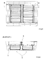
Figure 3 shows the valve framework shown inFigure 2 , viewed from the so called protected side, -
Figure 4 shows the valve framework shown inFigure 2 , viewed from the so called pressure side, -
Figure 5 shows the valve framework shown inFigure 2 in section along the line A-A inFigure 4 , -
Figure 6 shows the valve framework shown in Figure t1 viewed from the side, -
Figure 7 shows the blast valve shown inFigure 1 viewed from the so called protected side -
Figure 8 shows the blast valve shown inFigure 1 in section along the line B-B inFigure 7 , and -
Figure 9 the beam structure of the valve framework ofFigures 1 - 8 . -
Figure 1 shows a blast valve comprising avalve framework 1, to whichvalve blocks 3 are supported, and which framework comprises anopening 2, into whichvalve blocks 3 are arranged forming at least two adjacentvalve block columns 4 in such a manner, that thevalve blocks 3 essentially completely close theopening 2. - The valve framework may have been formed out of plates or blanks, by edging.
-
Figure 1 shows one such blast valve comprising twovalve block columns 4 such, that there are 3valve blocks 3 in eachvalve block column 4. To a person skilled in the art, it is obvious, that the number ofvalve blocks 3 can be different. The number ofvalve block columns 4 can be, for instance, three or four or more, and in onevalve block column 4 there can be, for instance, between two and twelvevalve blocks 3, or more. - In a blast valve there is at least one
valve block 3 comprising aframe 5 containing at least one flow channel 6, wherein each flow channel 6 is provided with a closing element 7, which is movable at least from an open position (not shown in the Figures) to a closed position (not shown in the Figures). - In the
opening 2 of thevalve framework 1, between two adjacentvalve block columns 4, a beam structure 6 is installed, being supported at its ends to thevalve framework 1 and to which thevalve blocks 3 partly are supported. The Figures show avalve framework 1 having onebeam structure 8, since the number ofvalve block columns 4 is two. In case there are threevalve block columns 4, there are, correspondingly, twobeam structures 8 in thevalve framework 1, and in case there are fourvalve block columns 4, there are, correspondingly, threebeam structures 8 in thevalve framework 1 such, that onebeam structure 8 always will be fitted between two adjacentvalve block columns 4, said beam structure being supported at its ends to thevalve framework 1 and to which beam structure thevalve blocks 3 partly are supported. - The
beam structure 8 comprises twoprofiles 9 of a U-shaped cross-section shape having theirwebs 10 connected such, that said twoprofiles 9 of a U-shaped cross-section shape form a structure of an I-shaped cross-section shape i.e. a structure similar to an I-beam. - The
beam structure 8 contains preferably, but not necessarily, at least oneprofile 9 of a U-shaped cross-section shape into the end of which afastening structure 11 for fastening of thebeam structure 8 to thevalve framework 1 has been formed by edging. In theFigures 9 , thebeam structure 8 comprises twoprofiles 9 of a U-shaped cross-section shape, into both ends of which afastening structure 11 has been formed by edging. In the figures, thebeam structure 8 is fastened to thevalve framework 1 by means of a bolt-nut combination 12. - The
beam structure 8 may preferably, but not necessarily, contain at least oneprofile 9 of a U-shaped cross-section shape to the end of which a separate fastening structure (not shown in the figures) has been attached for fastening thebeam structure 8 to thevalve framework 1. Such a separate fastening structure can be fastened, for example by welding, to thevalve framework 1. - The
beam structure 8 may preferably, but not necessarily, contain at least oneprofile 9 of a U-shaped cross-section shape, which at least partly perforates thevalve framework 1 for fastening thebeam structure 8 to thevalve framework 1. - The
beam structure 8 contains preferably, but not necessarily, at least oneprofile 9 of a U-shaped cross-section shape formed out of a blank by edging (not shown in the Figures) such, that a profile of a U-shaped cross-section shape comprising aweb 10 and twoflanges 13 is formed out of the blank by edging. - The blast valve contains preferably, but not necessarily, a
beam structure 8, the twoprofiles 9 of which of a U-shaped cross-section shape are fastened to each other. The figures show such a blast valve, wherein the twoprofiles 9 of a U-shaped cross-section shape of thebeam structure 8 are fastened to each other with a bolt-nut combination 13. - The blast valve contains preferably, but not necessarily, a
beam structure 8, the twoprofiles 9 of which of a U-shaped cross-section shape are essentially identical in cross-section shape. - The blast valve contains preferably, but not necessarily, a
beam structure 8, the twoprofiles 9 of which of a U-shaped cross-section shape are of essentially the same length. - The blast valve contains preferably, but not necessarily, at least one
valve block 3, in which each closing element 7 is adapted to move, influenced by a blast, from an open position to a closed position. - The blast valve contains preferably, but not necessarily, at least one
valve block 3, in which each closing element 7 spring loaded such, that the closing element 7, influenced by a blast, moves to a closed position and, after the blast, back to an open position. - The blast valve contains preferably, but not necessarily, at least one
valve block 3, in which each closing element 7 spring loaded such, that the closing element 7 can move in two directions from the open position; to a first closed position (not shown in the Figures) for preventing an overpressure from forming in the protected space and, correspondingly, to a second closed position (not shown in the Figures) for preventing a vacuum from forming in the protected space. Such avalve block 3 is presented in the Finnish Patent publicationFI 75994 - Alternatively, the
valve block 3 can be such, that it contains at least onevalve block 3, in which each closing element 7 spring loaded such, that the closing element 7, influenced by a blast, moves to a closed position and that the closing element 7 remains in the closed position after the blast. Then, the closing elements 7 can be such, that they manually can be switched back from the closed position to an open position or such, that they permanently remain in the closed position. - The blast valve can be such, that it is intended to be installed surface mounted by e.g. welding or bolting at an opening of the space to be protected. Alternatively, the blast valve can be such, that it is intended to be cast, at least partly, into a concrete wall. The blast valve can also be such, that it is intended to be installed in an air-conditioning duct or between two air-conditioning ducts. An object of the invention is also a
valve framework 1, to which valve blocks 3 can be supported and which comprises anopening 2, into which valve blocks 3 can be arranged to form at least two adjacentvalve block columns 4 such, that the valve blocks 3 essentially completely close theopening 2. - The
valve framework 1 can be formed out of plates or blanks by edging. - The
valve framework 1 comprises abeam structure 8 arranged into theopening 2, which beam structure is supported at its ends to thevalve framework 1 and to which at least onevalve block 3, at least partly, can be supported. - In the
opening 2 of thevalve framework 1 such abeam structure 8 is arranged, which comprises twoprofiles 9 of a U-shaped cross-section shape thewebs 10 of which are interconnected such, that said twoprofiles 9 of a U-shaped cross-section shape form a structure of an I-shaped cross-section shape. - The
beam structure 8 contains preferably, but not necessarily, at least oneprofile 9 of a U-shaped cross-section shape to the end of which afastening structure 11 has been formed by edging for fastening thebeam structure 8 to thevalve framework 1. - The
beam structure 8 contains preferably, but not necessarily, at least oneprofile 9 of a U-shaped cross-section shape to the end of which a separate fastening structure (not shown in the Figures) has been attached for fastening thebeam structure 8 to thevalve framework 1. - The
beam structure 8 contains preferably, but not necessarily, at least oneprofile 9 of a U-shaped cross-section shape, which at least partly perforates (not shown in the figures) thevalve framework 1 for fastening thebeam structure 8 to thevalve framework 1. - The
beam structure 8 contains preferably, but not necessarily, at least oneprofile 9 of a U-shaped cross-section shape formed out of a blank by edging such, that a profile of a U-shaped cross-section shape comprising a web and two flanges is formed out of the blank by edging. - The valve framework may contain a
beam structure 8, the twoprofiles 9 of which of a U-shaped cross-section shape are fastened to each other. - The valve framework may contain a
beam structure 8, the twoprofiles 9 of which of a U-shaped cross-section shape are essentially identical in cross-section shape. - The valve framework may contain a
beam structure 8, the twoprofiles 9 of which of a U-shaped cross-section shape are of essentially the same length. - Into the
valve framework 1 such valve blocks 3, for example, can be arranged, in which each closing element 7 is adapted to move, influenced by a blast, from an open position to a closed position. - Into the
valve framework 1 such valve blocks 3, for example, can be arranged, in which each closing element 7 spring loaded such, that the closing element 7 moves, influenced by a blast, to a closed position and, after the blast, back to the open position. - Into the
valve framework 1 such valve blocks 3, for example, can be arranged, in which each closing element 7 spring loaded such, that the closing element 7 can move in two directions from an open position; to a first closed position (not shown in the Figures) for preventing an overpressure from forming in the protected space and, correspondingly, to a second closed position (not shown in the Figures) for preventing a vacuum from forming in the protected space. Such avalve block 3 is presented in the Finnish Patent publicationFI 75994 - Into the
valve framework 1 such valve blocks 3, for example, can be arranged, in which each closing element 7 spring loaded such, that the closing element 7, influenced by a blast, moves to a closed position and that the closing element 7 remains in the closed position after the blast. Then, the closing elements 7 can be such, that they manually can be switched back from the closed position to an open position or, that they permanently remain in the closed position. - Into the
valve framework 1 such valve blocks 3, for example, can be arranged, in which each closing element 7 manually can be moved between an open position and a closed position. - To a person skilled in the art, it is evident that, with advances in technology, the basic idea of the invention can be implemented in many different ways. Thus, the invention and its embodiments are not limited to the examples described above, but rather, they can vary within the scope of the patent claims.
Claims (18)
- A blast valve comprising a valve framework (1), to which valve blocks (3) can be supported, and which comprises an opening (2), into which valve blocks (3) are arranged to form at least two adjacent valve block columns (4) such, that the valve blocks (3) essentially completely close the opening (2),
wherein there is at least one valve block (3) having a frame (5) including at least one flow channel (6), a closing element (7) having been arranged into each flow channel (6), which closing element (7) can be moved at least from an open position to a closed position, and
wherein, into the opening (2) in the valve framework (1), in between two adjacent valve block columns (4), a beam structure (8) is arranged being supported at its ends to the valve framework (1) and to which beam structure (8) at least one valve block (3) partly is supported,
characterized in the beam structure (8) between two adjacent valve block columns (4), which beam structure comprises two profiles (9) of a U-shaped cross-section shape having their webs (10) interconnected such, that said two profiles (9) of a U-shaped cross-section shape form a structure of an I-shaped cross-section shape. - The blast valve according Claim 1, characterized in, that the beam structure (8) comprises at least one profile (9) of a U-shaped cross-section shape at the end of which a fastening structure has been formed by edging for fastening the beam structure (8) to the valve framework (1).
- The blast valve according Claim 1 or 2, characterized in, that the beam structure (8) comprises at least one profile (9) of a U-shaped cross-section shape to the end of which a separate fastening structure has been attached for fastening the beam structure (8) to the valve framework (1).
- The blast valve according to any one of the Claims 1 - 3, characterized in, that the beam structure (8) comprises at least one profile (9) of a U-shaped cross-section shape, which profile at least partly perforates the valve framework (1) for fastening the beam structure (8) to the valve framework (1).
- The blast valve according to any one of the Claims 1 - 4, characterized in, that the beam structure (8) comprises at least one profile (9) of a U-shaped cross-section shape, which profile is formed out of a blank by edging such, that, out of the blank, a profile (9) of a U-shaped cross-section shape comprising a web and two flanges is formed by edging.
- The blast valve according to any one of the Claims 1 - 5, characterized in, that it comprises a beam structure (8), the two profiles (9) of a U-shaped cross-section shape of which are attached to each other.
- The blast valve according to any one of the Claims 1 - 6, characterized in, that it comprises a beam structure (8), the two profiles (9) of a U-shaped cross-section shape of which are essentially identical in cross-section shape.
- The blast valve according to any one of the Claims 1 - 7, characterized in, that it comprises a beam structure (8), the two profiles (9) of a U-shaped cross-section shape of which are of essentially the same length.
- The blast valve according to any one of the Claims 1 - 8, characterized in, that it comprises at least one valve block (3) into which a closing element (7) is arranged to move, influenced by a blast, from an open position to closed position.
- The blast valve according to any one of the Claims 1 - 9, characterized in, that it comprises at least one valve block (3) in which each closing element (7) is spring loaded such, that each closing element (7) is adapted to move, influenced by a blast, from an open position to a closed position, and such, that each closing element (7) is adapted to move back to the open position after the blast.
- A valve framework (1), to which valve blocks (3) can be supported and which comprises an opening (2), into which valve blocks (3) can be arranged to form at least two adjacent valve block columns (4) such, that the valve blocks (3) essentially completely close the opening (2),
said valve framework (1) comprising a beam structure (8) arranged in the opening (2), which beam structure (8), at its ends, is supported to the valve framework (1), and to which the at least one valve block (3) at least partly can be supported,
characterized in the beam structure (8) arranged in the opening (2) of the valve framework (1), said beam structure (8) comprising two profiles (9) of a U-shaped cross-section shape having their webs (10) interconnected such, that said two profiles (9) of a U-shaped cross-section shape form a structure of an I-shaped cross-section shape. - The valve framework according to Claim 11, characterized in, that the beam structure (8) comprises at least one profile (9) of a U-shaped cross-section shape at the end of which a fastening structure (11) has been formed by edging for fastening the beam structure (8) to the valve framework (1).
- The valve framework according to Claim 11 or 12, characterized in, that the beam structure (8) comprises at least one profile (9) of a U-shaped cross-section shape to the end of which a separate fastening structure has been attached for fastening the beam structure (8) to the valve framework (1).
- The valve framework according to any one of the Claims 11 - 13, characterized in, that the beam structure (8) comprises at least one profile (9) of a U-shaped cross-section shape, which profile (9) at least partly perforates the valve framework (1) for fastening the beam structure (8) to the valve framework (1).
- The valve framework according to any one of the Claims 11 - 14, characterized in, that the beam structure (8) comprises at least one profile (9) of a U-shaped cross-section shape, which profile is formed out of a blank by edging such, that, out of the blank, a profile (9) of a U-shaped cross-section shape comprising a web and two flanges is formed by edging.
- The valve framework according to any one of the Claims 11 - 15, characterized in, that it comprises a beam structure (8), the two profiles (9) of which of a U-shaped cross-section shape are attached to each other.
- The valve framework according to any one of the Claims 11 - 16, characterized in, that it comprises a beam structure (8), the two profiles (9) of which of a U-shaped cross-section shape are essentially identical in cross-section shape.
- The valve framework according to any one of the Claims 11 - 17, characterized in, that it comprises a beam structure (8), the two profiles (9) of which of a U-shaped cross-section shape are of essentially the same length.
Applications Claiming Priority (1)
| Application Number | Priority Date | Filing Date | Title |
|---|---|---|---|
| FI20106377A FI124126B (en) | 2010-12-29 | 2010-12-29 | Pressure valve and valve frame construction |
Publications (3)
| Publication Number | Publication Date |
|---|---|
| EP2472192A2 true EP2472192A2 (en) | 2012-07-04 |
| EP2472192A3 EP2472192A3 (en) | 2017-07-12 |
| EP2472192B1 EP2472192B1 (en) | 2020-02-19 |
Family
ID=43415065
Family Applications (1)
| Application Number | Title | Priority Date | Filing Date |
|---|---|---|---|
| EP11195881.5A Active EP2472192B1 (en) | 2010-12-29 | 2011-12-28 | Pressure valve and valve framework |
Country Status (2)
| Country | Link |
|---|---|
| EP (1) | EP2472192B1 (en) |
| FI (1) | FI124126B (en) |
Cited By (4)
| Publication number | Priority date | Publication date | Assignee | Title |
|---|---|---|---|---|
| WO2015067850A1 (en) * | 2013-11-05 | 2015-05-14 | Temet Oy | Blast damper, blast damper assembly and method for arranging a blast damper to a building |
| WO2016124895A1 (en) * | 2015-02-02 | 2016-08-11 | Flamgard Engineering Limited | Fire damper assemblies |
| WO2016142578A1 (en) * | 2015-03-06 | 2016-09-15 | Temet Oy | Framework, blast damper and method |
| WO2018091786A1 (en) * | 2016-11-21 | 2018-05-24 | Temet Oy | Air blast valve |
Citations (1)
| Publication number | Priority date | Publication date | Assignee | Title |
|---|---|---|---|---|
| FI75994B (en) | 1986-05-15 | 1988-05-31 | Temet Oy | AVSTAENGNINGSANORDNING. |
Family Cites Families (5)
| Publication number | Priority date | Publication date | Assignee | Title |
|---|---|---|---|---|
| US4579047A (en) * | 1984-12-13 | 1986-04-01 | Pullman Construction Industries, Inc. | Fire damper assembly for sealed penetrations |
| GB8615194D0 (en) * | 1986-06-21 | 1986-07-23 | Gradwood Ltd | Automatic ventilator |
| ATE449887T1 (en) * | 1999-02-22 | 2009-12-15 | Sadef Nv | BUILDING FRAME WITH SIGMA PROFILES |
| FI123214B (en) * | 2008-05-09 | 2012-12-31 | Temet Oy | pressure valve |
| DE102008040462B4 (en) * | 2008-07-16 | 2013-09-12 | Sommer Metallbau-Stahlbau Gmbh & Co. Kg | Pressure surge damper |
-
2010
- 2010-12-29 FI FI20106377A patent/FI124126B/en active IP Right Grant
-
2011
- 2011-12-28 EP EP11195881.5A patent/EP2472192B1/en active Active
Patent Citations (1)
| Publication number | Priority date | Publication date | Assignee | Title |
|---|---|---|---|---|
| FI75994B (en) | 1986-05-15 | 1988-05-31 | Temet Oy | AVSTAENGNINGSANORDNING. |
Cited By (5)
| Publication number | Priority date | Publication date | Assignee | Title |
|---|---|---|---|---|
| WO2015067850A1 (en) * | 2013-11-05 | 2015-05-14 | Temet Oy | Blast damper, blast damper assembly and method for arranging a blast damper to a building |
| WO2016124895A1 (en) * | 2015-02-02 | 2016-08-11 | Flamgard Engineering Limited | Fire damper assemblies |
| WO2016142578A1 (en) * | 2015-03-06 | 2016-09-15 | Temet Oy | Framework, blast damper and method |
| EP3265728A4 (en) * | 2015-03-06 | 2018-12-05 | Temet OY | Framework, blast damper and method |
| WO2018091786A1 (en) * | 2016-11-21 | 2018-05-24 | Temet Oy | Air blast valve |
Also Published As
| Publication number | Publication date |
|---|---|
| FI20106377A7 (en) | 2012-06-30 |
| EP2472192B1 (en) | 2020-02-19 |
| EP2472192A3 (en) | 2017-07-12 |
| FI124126B (en) | 2014-03-31 |
| FI20106377L (en) | 2012-06-30 |
| FI20106377A0 (en) | 2010-12-29 |
Similar Documents
| Publication | Publication Date | Title |
|---|---|---|
| EP2472192B1 (en) | Pressure valve and valve framework | |
| EP2965017B1 (en) | Air-distributing device | |
| DE102008006979A1 (en) | Device for explosion forming | |
| DE102009000620A1 (en) | Fire protection design | |
| WO2014208031A1 (en) | Refractory coated structure for pipe insert in steel beams | |
| EP3543622B1 (en) | Acoustic dampening device and room ventilation system with such an acoustic dampening device | |
| EP2604774B1 (en) | Smoke extraction duct | |
| CA3015813A1 (en) | Waterproofing assemblies and prefabricated wall panels including the same | |
| JP5008610B2 (en) | Pillars and buildings | |
| DE102007003077B4 (en) | Housing for a pressure chamber | |
| DE19631291C2 (en) | insulation panel | |
| EP2531668B1 (en) | Closable fire protection opening for drywall construction | |
| EP2910682A1 (en) | Flat sound insulation structure | |
| EP2787148A1 (en) | Demolition device, in particular hydraulic demolition shears | |
| WO2002037011A1 (en) | Device for sealing-off pipe or cable feedthroughs in walls in a fireproof manner | |
| DE102010037202B4 (en) | Structure, in particular building of a nuclear power plant | |
| EP4043660A1 (en) | System module for constructing a splitter wall and flexibly insertable splitter protection cage | |
| DE102012109072B4 (en) | chimney element | |
| US20130225066A1 (en) | Protective cover for a ventilation opening | |
| EP2422073B1 (en) | Device for converting wave energy into an air flow and method for the production thereof | |
| DE202016004209U1 (en) | Pressure relief device for explosive decoupling of two system components | |
| WO2021156206A1 (en) | Passively operating mechanical functional unit for a shock wave protection valve, and shock wave protection valve | |
| DE102015013641A1 (en) | Rekuparatives method for heat recovery with fixed exchange surfaces and ventilation system with at least one interface heat exchanger | |
| AT6561U1 (en) | PANEL-SHAPED MOLDED PART AND AIR OR CABLE CHANNEL COMPONENT | |
| WO2013017274A1 (en) | Explosion protection device for explosion-decoupling of two parts of a plant |
Legal Events
| Date | Code | Title | Description |
|---|---|---|---|
| 17P | Request for examination filed |
Effective date: 20111228 |
|
| AK | Designated contracting states |
Kind code of ref document: A2 Designated state(s): AL AT BE BG CH CY CZ DE DK EE ES FI FR GB GR HR HU IE IS IT LI LT LU LV MC MK MT NL NO PL PT RO RS SE SI SK SM TR |
|
| AX | Request for extension of the european patent |
Extension state: BA ME |
|
| PUAI | Public reference made under article 153(3) epc to a published international application that has entered the european phase |
Free format text: ORIGINAL CODE: 0009012 |
|
| PUAL | Search report despatched |
Free format text: ORIGINAL CODE: 0009013 |
|
| AK | Designated contracting states |
Kind code of ref document: A3 Designated state(s): AL AT BE BG CH CY CZ DE DK EE ES FI FR GB GR HR HU IE IS IT LI LT LU LV MC MK MT NL NO PL PT RO RS SE SI SK SM TR |
|
| AX | Request for extension of the european patent |
Extension state: BA ME |
|
| RIC1 | Information provided on ipc code assigned before grant |
Ipc: F24F 13/075 20060101ALI20170607BHEP Ipc: F24F 13/14 20060101AFI20170607BHEP Ipc: F24F 13/15 20060101ALI20170607BHEP |
|
| GRAP | Despatch of communication of intention to grant a patent |
Free format text: ORIGINAL CODE: EPIDOSNIGR1 |
|
| STAA | Information on the status of an ep patent application or granted ep patent |
Free format text: STATUS: GRANT OF PATENT IS INTENDED |
|
| INTG | Intention to grant announced |
Effective date: 20191009 |
|
| GRAS | Grant fee paid |
Free format text: ORIGINAL CODE: EPIDOSNIGR3 |
|
| GRAA | (expected) grant |
Free format text: ORIGINAL CODE: 0009210 |
|
| STAA | Information on the status of an ep patent application or granted ep patent |
Free format text: STATUS: THE PATENT HAS BEEN GRANTED |
|
| AK | Designated contracting states |
Kind code of ref document: B1 Designated state(s): AL AT BE BG CH CY CZ DE DK EE ES FI FR GB GR HR HU IE IS IT LI LT LU LV MC MK MT NL NO PL PT RO RS SE SI SK SM TR |
|
| REG | Reference to a national code |
Ref country code: GB Ref legal event code: FG4D |
|
| REG | Reference to a national code |
Ref country code: CH Ref legal event code: EP |
|
| REG | Reference to a national code |
Ref country code: DE Ref legal event code: R096 Ref document number: 602011065069 Country of ref document: DE |
|
| REG | Reference to a national code |
Ref country code: AT Ref legal event code: REF Ref document number: 1235417 Country of ref document: AT Kind code of ref document: T Effective date: 20200315 |
|
| REG | Reference to a national code |
Ref country code: IE Ref legal event code: FG4D |
|
| REG | Reference to a national code |
Ref country code: FI Ref legal event code: FGE |
|
| REG | Reference to a national code |
Ref country code: SE Ref legal event code: TRGR |
|
| REG | Reference to a national code |
Ref country code: NO Ref legal event code: T2 Effective date: 20200219 |
|
| REG | Reference to a national code |
Ref country code: NL Ref legal event code: MP Effective date: 20200219 |
|
| PG25 | Lapsed in a contracting state [announced via postgrant information from national office to epo] |
Ref country code: RS Free format text: LAPSE BECAUSE OF FAILURE TO SUBMIT A TRANSLATION OF THE DESCRIPTION OR TO PAY THE FEE WITHIN THE PRESCRIBED TIME-LIMIT Effective date: 20200219 |
|
| REG | Reference to a national code |
Ref country code: LT Ref legal event code: MG4D |
|
| PG25 | Lapsed in a contracting state [announced via postgrant information from national office to epo] |
Ref country code: LV Free format text: LAPSE BECAUSE OF FAILURE TO SUBMIT A TRANSLATION OF THE DESCRIPTION OR TO PAY THE FEE WITHIN THE PRESCRIBED TIME-LIMIT Effective date: 20200219 Ref country code: GR Free format text: LAPSE BECAUSE OF FAILURE TO SUBMIT A TRANSLATION OF THE DESCRIPTION OR TO PAY THE FEE WITHIN THE PRESCRIBED TIME-LIMIT Effective date: 20200520 Ref country code: IS Free format text: LAPSE BECAUSE OF FAILURE TO SUBMIT A TRANSLATION OF THE DESCRIPTION OR TO PAY THE FEE WITHIN THE PRESCRIBED TIME-LIMIT Effective date: 20200619 Ref country code: BG Free format text: LAPSE BECAUSE OF FAILURE TO SUBMIT A TRANSLATION OF THE DESCRIPTION OR TO PAY THE FEE WITHIN THE PRESCRIBED TIME-LIMIT Effective date: 20200519 Ref country code: HR Free format text: LAPSE BECAUSE OF FAILURE TO SUBMIT A TRANSLATION OF THE DESCRIPTION OR TO PAY THE FEE WITHIN THE PRESCRIBED TIME-LIMIT Effective date: 20200219 |
|
| PG25 | Lapsed in a contracting state [announced via postgrant information from national office to epo] |
Ref country code: NL Free format text: LAPSE BECAUSE OF FAILURE TO SUBMIT A TRANSLATION OF THE DESCRIPTION OR TO PAY THE FEE WITHIN THE PRESCRIBED TIME-LIMIT Effective date: 20200219 |
|
| PG25 | Lapsed in a contracting state [announced via postgrant information from national office to epo] |
Ref country code: SK Free format text: LAPSE BECAUSE OF FAILURE TO SUBMIT A TRANSLATION OF THE DESCRIPTION OR TO PAY THE FEE WITHIN THE PRESCRIBED TIME-LIMIT Effective date: 20200219 Ref country code: PT Free format text: LAPSE BECAUSE OF FAILURE TO SUBMIT A TRANSLATION OF THE DESCRIPTION OR TO PAY THE FEE WITHIN THE PRESCRIBED TIME-LIMIT Effective date: 20200712 Ref country code: RO Free format text: LAPSE BECAUSE OF FAILURE TO SUBMIT A TRANSLATION OF THE DESCRIPTION OR TO PAY THE FEE WITHIN THE PRESCRIBED TIME-LIMIT Effective date: 20200219 Ref country code: SM Free format text: LAPSE BECAUSE OF FAILURE TO SUBMIT A TRANSLATION OF THE DESCRIPTION OR TO PAY THE FEE WITHIN THE PRESCRIBED TIME-LIMIT Effective date: 20200219 Ref country code: EE Free format text: LAPSE BECAUSE OF FAILURE TO SUBMIT A TRANSLATION OF THE DESCRIPTION OR TO PAY THE FEE WITHIN THE PRESCRIBED TIME-LIMIT Effective date: 20200219 Ref country code: DK Free format text: LAPSE BECAUSE OF FAILURE TO SUBMIT A TRANSLATION OF THE DESCRIPTION OR TO PAY THE FEE WITHIN THE PRESCRIBED TIME-LIMIT Effective date: 20200219 Ref country code: ES Free format text: LAPSE BECAUSE OF FAILURE TO SUBMIT A TRANSLATION OF THE DESCRIPTION OR TO PAY THE FEE WITHIN THE PRESCRIBED TIME-LIMIT Effective date: 20200219 Ref country code: LT Free format text: LAPSE BECAUSE OF FAILURE TO SUBMIT A TRANSLATION OF THE DESCRIPTION OR TO PAY THE FEE WITHIN THE PRESCRIBED TIME-LIMIT Effective date: 20200219 Ref country code: CZ Free format text: LAPSE BECAUSE OF FAILURE TO SUBMIT A TRANSLATION OF THE DESCRIPTION OR TO PAY THE FEE WITHIN THE PRESCRIBED TIME-LIMIT Effective date: 20200219 |
|
| REG | Reference to a national code |
Ref country code: AT Ref legal event code: MK05 Ref document number: 1235417 Country of ref document: AT Kind code of ref document: T Effective date: 20200219 |
|
| REG | Reference to a national code |
Ref country code: DE Ref legal event code: R097 Ref document number: 602011065069 Country of ref document: DE |
|
| PLBE | No opposition filed within time limit |
Free format text: ORIGINAL CODE: 0009261 |
|
| STAA | Information on the status of an ep patent application or granted ep patent |
Free format text: STATUS: NO OPPOSITION FILED WITHIN TIME LIMIT |
|
| 26N | No opposition filed |
Effective date: 20201120 |
|
| PG25 | Lapsed in a contracting state [announced via postgrant information from national office to epo] |
Ref country code: AT Free format text: LAPSE BECAUSE OF FAILURE TO SUBMIT A TRANSLATION OF THE DESCRIPTION OR TO PAY THE FEE WITHIN THE PRESCRIBED TIME-LIMIT Effective date: 20200219 Ref country code: IT Free format text: LAPSE BECAUSE OF FAILURE TO SUBMIT A TRANSLATION OF THE DESCRIPTION OR TO PAY THE FEE WITHIN THE PRESCRIBED TIME-LIMIT Effective date: 20200219 |
|
| PG25 | Lapsed in a contracting state [announced via postgrant information from national office to epo] |
Ref country code: SI Free format text: LAPSE BECAUSE OF FAILURE TO SUBMIT A TRANSLATION OF THE DESCRIPTION OR TO PAY THE FEE WITHIN THE PRESCRIBED TIME-LIMIT Effective date: 20200219 Ref country code: PL Free format text: LAPSE BECAUSE OF FAILURE TO SUBMIT A TRANSLATION OF THE DESCRIPTION OR TO PAY THE FEE WITHIN THE PRESCRIBED TIME-LIMIT Effective date: 20200219 |
|
| PG25 | Lapsed in a contracting state [announced via postgrant information from national office to epo] |
Ref country code: MC Free format text: LAPSE BECAUSE OF FAILURE TO SUBMIT A TRANSLATION OF THE DESCRIPTION OR TO PAY THE FEE WITHIN THE PRESCRIBED TIME-LIMIT Effective date: 20200219 |
|
| PG25 | Lapsed in a contracting state [announced via postgrant information from national office to epo] |
Ref country code: LU Free format text: LAPSE BECAUSE OF NON-PAYMENT OF DUE FEES Effective date: 20201228 |
|
| PG25 | Lapsed in a contracting state [announced via postgrant information from national office to epo] |
Ref country code: MT Free format text: LAPSE BECAUSE OF FAILURE TO SUBMIT A TRANSLATION OF THE DESCRIPTION OR TO PAY THE FEE WITHIN THE PRESCRIBED TIME-LIMIT Effective date: 20200219 Ref country code: CY Free format text: LAPSE BECAUSE OF FAILURE TO SUBMIT A TRANSLATION OF THE DESCRIPTION OR TO PAY THE FEE WITHIN THE PRESCRIBED TIME-LIMIT Effective date: 20200219 |
|
| PG25 | Lapsed in a contracting state [announced via postgrant information from national office to epo] |
Ref country code: MK Free format text: LAPSE BECAUSE OF FAILURE TO SUBMIT A TRANSLATION OF THE DESCRIPTION OR TO PAY THE FEE WITHIN THE PRESCRIBED TIME-LIMIT Effective date: 20200219 Ref country code: AL Free format text: LAPSE BECAUSE OF FAILURE TO SUBMIT A TRANSLATION OF THE DESCRIPTION OR TO PAY THE FEE WITHIN THE PRESCRIBED TIME-LIMIT Effective date: 20200219 |
|
| P01 | Opt-out of the competence of the unified patent court (upc) registered |
Effective date: 20230315 |
|
| P02 | Opt-out of the competence of the unified patent court (upc) changed |
Effective date: 20230404 |
|
| P02 | Opt-out of the competence of the unified patent court (upc) changed |
Effective date: 20230530 |
|
| REG | Reference to a national code |
Ref country code: CH Ref legal event code: U11 Free format text: ST27 STATUS EVENT CODE: U-0-0-U10-U11 (AS PROVIDED BY THE NATIONAL OFFICE) Effective date: 20260101 |
|
| PGFP | Annual fee paid to national office [announced via postgrant information from national office to epo] |
Ref country code: DE Payment date: 20251112 Year of fee payment: 15 |
|
| PGFP | Annual fee paid to national office [announced via postgrant information from national office to epo] |
Ref country code: GB Payment date: 20251114 Year of fee payment: 15 |
|
| PGFP | Annual fee paid to national office [announced via postgrant information from national office to epo] |
Ref country code: NO Payment date: 20251113 Year of fee payment: 15 |
|
| PGFP | Annual fee paid to national office [announced via postgrant information from national office to epo] |
Ref country code: FI Payment date: 20251110 Year of fee payment: 15 |
|
| PGFP | Annual fee paid to national office [announced via postgrant information from national office to epo] |
Ref country code: FR Payment date: 20251112 Year of fee payment: 15 |
|
| PGFP | Annual fee paid to national office [announced via postgrant information from national office to epo] |
Ref country code: TR Payment date: 20251107 Year of fee payment: 15 Ref country code: BE Payment date: 20251124 Year of fee payment: 15 |
|
| PGFP | Annual fee paid to national office [announced via postgrant information from national office to epo] |
Ref country code: SE Payment date: 20251111 Year of fee payment: 15 |
|
| PGFP | Annual fee paid to national office [announced via postgrant information from national office to epo] |
Ref country code: IE Payment date: 20251117 Year of fee payment: 15 |
|
| PGFP | Annual fee paid to national office [announced via postgrant information from national office to epo] |
Ref country code: CH Payment date: 20260101 Year of fee payment: 15 |