EP2472182A2 - Sculpted trailing edge swirler combustion premixer and method - Google Patents
Sculpted trailing edge swirler combustion premixer and method Download PDFInfo
- Publication number
- EP2472182A2 EP2472182A2 EP11194559A EP11194559A EP2472182A2 EP 2472182 A2 EP2472182 A2 EP 2472182A2 EP 11194559 A EP11194559 A EP 11194559A EP 11194559 A EP11194559 A EP 11194559A EP 2472182 A2 EP2472182 A2 EP 2472182A2
- Authority
- EP
- European Patent Office
- Prior art keywords
- vanes
- premixer
- center body
- rim
- flow
- Prior art date
- Legal status (The legal status is an assumption and is not a legal conclusion. Google has not performed a legal analysis and makes no representation as to the accuracy of the status listed.)
- Withdrawn
Links
- 238000000034 method Methods 0.000 title claims abstract description 19
- 238000002485 combustion reaction Methods 0.000 title description 2
- 239000000446 fuel Substances 0.000 claims abstract description 60
- 239000012530 fluid Substances 0.000 claims abstract description 14
- 239000008246 gaseous mixture Substances 0.000 claims description 17
- 238000004519 manufacturing process Methods 0.000 claims description 8
- MWUXSHHQAYIFBG-UHFFFAOYSA-N nitrogen oxide Inorganic materials O=[N] MWUXSHHQAYIFBG-UHFFFAOYSA-N 0.000 description 29
- 239000007789 gas Substances 0.000 description 19
- 239000000203 mixture Substances 0.000 description 7
- 239000007788 liquid Substances 0.000 description 4
- VNWKTOKETHGBQD-UHFFFAOYSA-N methane Chemical compound C VNWKTOKETHGBQD-UHFFFAOYSA-N 0.000 description 4
- 238000009792 diffusion process Methods 0.000 description 3
- 239000003345 natural gas Substances 0.000 description 2
- 230000009467 reduction Effects 0.000 description 2
- 238000006722 reduction reaction Methods 0.000 description 2
- QVGXLLKOCUKJST-UHFFFAOYSA-N atomic oxygen Chemical compound [O] QVGXLLKOCUKJST-UHFFFAOYSA-N 0.000 description 1
- 238000010531 catalytic reduction reaction Methods 0.000 description 1
- 238000010586 diagram Methods 0.000 description 1
- 230000000694 effects Effects 0.000 description 1
- 238000005516 engineering process Methods 0.000 description 1
- 239000003344 environmental pollutant Substances 0.000 description 1
- 230000003278 mimic effect Effects 0.000 description 1
- 238000012986 modification Methods 0.000 description 1
- 230000004048 modification Effects 0.000 description 1
- 239000001301 oxygen Substances 0.000 description 1
- 229910052760 oxygen Inorganic materials 0.000 description 1
- 231100000719 pollutant Toxicity 0.000 description 1
- 238000010248 power generation Methods 0.000 description 1
- 238000005245 sintering Methods 0.000 description 1
- 230000007704 transition Effects 0.000 description 1
- 239000012498 ultrapure water Substances 0.000 description 1
Images


Classifications
-
- F—MECHANICAL ENGINEERING; LIGHTING; HEATING; WEAPONS; BLASTING
- F23—COMBUSTION APPARATUS; COMBUSTION PROCESSES
- F23R—GENERATING COMBUSTION PRODUCTS OF HIGH PRESSURE OR HIGH VELOCITY, e.g. GAS-TURBINE COMBUSTION CHAMBERS
- F23R3/00—Continuous combustion chambers using liquid or gaseous fuel
- F23R3/02—Continuous combustion chambers using liquid or gaseous fuel characterised by the air-flow or gas-flow configuration
- F23R3/04—Air inlet arrangements
- F23R3/10—Air inlet arrangements for primary air
- F23R3/12—Air inlet arrangements for primary air inducing a vortex
- F23R3/14—Air inlet arrangements for primary air inducing a vortex by using swirl vanes
-
- F—MECHANICAL ENGINEERING; LIGHTING; HEATING; WEAPONS; BLASTING
- F02—COMBUSTION ENGINES; HOT-GAS OR COMBUSTION-PRODUCT ENGINE PLANTS
- F02C—GAS-TURBINE PLANTS; AIR INTAKES FOR JET-PROPULSION PLANTS; CONTROLLING FUEL SUPPLY IN AIR-BREATHING JET-PROPULSION PLANTS
- F02C3/00—Gas-turbine plants characterised by the use of combustion products as the working fluid
- F02C3/04—Gas-turbine plants characterised by the use of combustion products as the working fluid having a turbine driving a compressor
-
- F—MECHANICAL ENGINEERING; LIGHTING; HEATING; WEAPONS; BLASTING
- F02—COMBUSTION ENGINES; HOT-GAS OR COMBUSTION-PRODUCT ENGINE PLANTS
- F02C—GAS-TURBINE PLANTS; AIR INTAKES FOR JET-PROPULSION PLANTS; CONTROLLING FUEL SUPPLY IN AIR-BREATHING JET-PROPULSION PLANTS
- F02C7/00—Features, components parts, details or accessories, not provided for in, or of interest apart form groups F02C1/00 - F02C6/00; Air intakes for jet-propulsion plants
- F02C7/22—Fuel supply systems
-
- F—MECHANICAL ENGINEERING; LIGHTING; HEATING; WEAPONS; BLASTING
- F02—COMBUSTION ENGINES; HOT-GAS OR COMBUSTION-PRODUCT ENGINE PLANTS
- F02C—GAS-TURBINE PLANTS; AIR INTAKES FOR JET-PROPULSION PLANTS; CONTROLLING FUEL SUPPLY IN AIR-BREATHING JET-PROPULSION PLANTS
- F02C9/00—Controlling gas-turbine plants; Controlling fuel supply in air- breathing jet-propulsion plants
- F02C9/26—Control of fuel supply
-
- F—MECHANICAL ENGINEERING; LIGHTING; HEATING; WEAPONS; BLASTING
- F23—COMBUSTION APPARATUS; COMBUSTION PROCESSES
- F23C—METHODS OR APPARATUS FOR COMBUSTION USING FLUID FUEL OR SOLID FUEL SUSPENDED IN A CARRIER GAS OR AIR
- F23C7/00—Combustion apparatus characterised by arrangements for air supply
- F23C7/002—Combustion apparatus characterised by arrangements for air supply the air being submitted to a rotary or spinning motion
- F23C7/004—Combustion apparatus characterised by arrangements for air supply the air being submitted to a rotary or spinning motion using vanes
-
- F—MECHANICAL ENGINEERING; LIGHTING; HEATING; WEAPONS; BLASTING
- F23—COMBUSTION APPARATUS; COMBUSTION PROCESSES
- F23R—GENERATING COMBUSTION PRODUCTS OF HIGH PRESSURE OR HIGH VELOCITY, e.g. GAS-TURBINE COMBUSTION CHAMBERS
- F23R3/00—Continuous combustion chambers using liquid or gaseous fuel
- F23R3/28—Continuous combustion chambers using liquid or gaseous fuel characterised by the fuel supply
- F23R3/286—Continuous combustion chambers using liquid or gaseous fuel characterised by the fuel supply having fuel-air premixing devices
-
- F—MECHANICAL ENGINEERING; LIGHTING; HEATING; WEAPONS; BLASTING
- F23—COMBUSTION APPARATUS; COMBUSTION PROCESSES
- F23D—BURNERS
- F23D2900/00—Special features of, or arrangements for burners using fluid fuels or solid fuels suspended in a carrier gas
- F23D2900/14—Special features of gas burners
- F23D2900/14021—Premixing burners with swirling or vortices creating means for fuel or air
-
- Y—GENERAL TAGGING OF NEW TECHNOLOGICAL DEVELOPMENTS; GENERAL TAGGING OF CROSS-SECTIONAL TECHNOLOGIES SPANNING OVER SEVERAL SECTIONS OF THE IPC; TECHNICAL SUBJECTS COVERED BY FORMER USPC CROSS-REFERENCE ART COLLECTIONS [XRACs] AND DIGESTS
- Y02—TECHNOLOGIES OR APPLICATIONS FOR MITIGATION OR ADAPTATION AGAINST CLIMATE CHANGE
- Y02T—CLIMATE CHANGE MITIGATION TECHNOLOGIES RELATED TO TRANSPORTATION
- Y02T10/00—Road transport of goods or passengers
- Y02T10/10—Internal combustion engine [ICE] based vehicles
- Y02T10/30—Use of alternative fuels, e.g. biofuels
-
- Y—GENERAL TAGGING OF NEW TECHNOLOGICAL DEVELOPMENTS; GENERAL TAGGING OF CROSS-SECTIONAL TECHNOLOGIES SPANNING OVER SEVERAL SECTIONS OF THE IPC; TECHNICAL SUBJECTS COVERED BY FORMER USPC CROSS-REFERENCE ART COLLECTIONS [XRACs] AND DIGESTS
- Y10—TECHNICAL SUBJECTS COVERED BY FORMER USPC
- Y10T—TECHNICAL SUBJECTS COVERED BY FORMER US CLASSIFICATION
- Y10T29/00—Metal working
- Y10T29/49—Method of mechanical manufacture
- Y10T29/494—Fluidic or fluid actuated device making
Definitions
- Embodiments of the subject matter disclosed herein generally relate to methods and systems used to generate a substantially uniform compressed air-fuel mixture used in a turbo-compressor engine, and, more particularly, to a swirler having a set of vanes with sculpted trailing edges.
- FIG. 1 is a graph illustrating the correlation between an amount of NOx emissions and the temperature of the flame. The amount of NOx on the y-axis of the graph is expressed in parts-per-million by volume (ppmvd) corrected for 15% O 2 .
- Aero-derivative engines are frequently used on oil and gas platforms used for exploration and exploitation of subsea reservoirs. These engines may be seen as modified aircraft engines, which instead of being used for propulsion are used to generate mechanical drive for oil and gas pumps or as power generators.
- the aero-derivative engines are used on oil and gas platforms because of their high power and efficiency as well as compactness.
- the aero-derivative engines are typically modified to use natural gas as fuel (instead of liquid fuel), but liquid fuel could also be used as backup fuel.
- Another known method of reducing the temperature of the flame and consequently the NOx emissions is mixing uniformly fuel and compressed air before the burning.
- a diffusion flame there are regions having different proportions of fuel and air, for example characterized by stoichiometry ratios of 0.1, 1, 2, and 5.
- a premixer a constant stoichiometry ratio of 0.5 may be achieved.
- dry low NOx a uniform mixture of fuel and compressed air technology is known as dry low NOx.
- a premixer which is traditionally placed between a compressor and a turbine may be configured to achieve a uniform mixture of compressed air and fuel.
- the premixer may be part of a combustor.
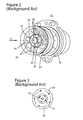
- FIG. 2 An exploded view of a conventional aero-derivative premixer 10 is illustrated in Figure 2 .
- the compressed air produced by a compressor flows into the premixer 10 in a flow direction 15.
- the premixer 10 includes a mixing part 20 and a shroud 30.
- the mixing part 20 and the shroud 30 are configured to engage with each other.
- a double annular counter rotating swirler 60 has a center body 70 and two sets of vanes 80 and 90 separated by an intermediate rim 85.
- the vanes 80 form an inner swirler configured to direct a flow passing therethrough such as to generate an inner rotation in a plane perpendicular to the flow direction 15.
- the vanes 90 form a counter-rotating swirler configured to direct a flow passing therethrough such as to generate an outer rotation in the plane perpendicular to the flow direction 15, the outer rotation being opposite to the inner rotation.
- the double annular counter rotating conventional swirler 60 has a complicated geometry, is expensive to manufacture and hard to control from a fluid dynamics perspective since turbulence is generally a violent unstable phenomenon.
- a premixer has a mixing part configured to receive a gas flow input in a flow direction and fluid fuel injected substantially perpendicularly to the flow direction.
- the mixing part includes a rim configured to define a substantially cylindrical shape and a swirler with (i) a center body located substantially in a middle of the cylindrical shape along the flow direction, and (ii) a set of vanes extending from the center body towards the rim, the vanes being configured to determine a rotation motion inside a flow that includes the received gas flow and the injected fuel when the flow passes through the mixing part, at least some of the vanes having a trailing edge with a waving profile configured to generate mixing zones inside the flow thereafter.
- a turbo-engine has a compressor configured to compress a gas flow passing therethrough, a turbine configured to receive a gaseous mixture flow, and a premixer located between the compressor and the turbine, and configured to mix the compressed gas exiting the compressor and fluid fuel to yield the gaseous mixture, and to output the gaseous mixture towards the turbine.
- the premixer has a mixing part configured to receive the compressed gas input in a flow direction and the fuel injected substantially perpendicular to the flow direction.
- the mixing part includes a rim configured to define a substantially cylindrical shape and a swirler with (i) a center body located substantially in a middle of the cylindrical shape along the flow direction, and (ii) a set of vanes extending from the center body towards the rim, the vanes being configured to determine a rotation motion inside the gaseous mixture, when the gaseous mixture passes through the mixing part. At least some of the vanes have a trailing edge with a waving profile configured to generate mixing zones inside the flow thereafter.
- a method of manufacturing a premixer includes mounting vanes around a center body located substantially in a middle of a rim having a cylindrical shape, , fuel orifices being located on at least one of the rim and the center body and being configured to inject fluid fuel radially.
- the vanes extend from the center body towards the rim, and are configured to determine a rotation motion inside a flow passing through the mixing part, at least some of the vanes having a trailing edge with a waving profile.
- the method further includes mounting the rim with the center body and the vanes inside a first end of a shroud, to form a duct between the rim and a second of the shroud.
- a turbo-engine 100 generally includes a compressor 108, a premixer 110, and a turbine 112, as schematically represented in Figure 4 .
- a single premixer 110 is illustrated and discussed hereinafter, it is known in the art that multiple premixers may be placed between the compressor 108 and the turbine 112.
- the premixer 110 may be part of a combustor configured to initiate and host the flame, for example, in a combustion chamber. However, the burning may alternatively take place inside the turbine 112. An exact location of the burning is not relevant or limiting for the embodiments discussed hereinafter.
- Air or another gas including oxygen (for simplicity referred to as air in the following description) is compressed in the compressor 105, mixed with fuel received from a supply 114 in the premixer 110, burned to generate hot, high-pressure gases which are then expanded in the turbine 112.
- transition from the compressor 108 to the premixer 110 and then to the turbine 112 are represented using dashed lines as other components may exist in-between.
- the fuel may be in a gaseous form (e.g., natural gas) or in a liquid form, and, thus, may be characterized as being fluid fuel.
- FIG. 5 is an exploded view of the premixer 110 according to an embodiment.
- the compressed air produced by the compressor 108 enters the premixer 110 along a flow direction 115.
- the premixer 110 includes a mixing part 120 and a shroud 130 configured to engage with each other.
- the shroud 130 may receive at least partially the mixing part 120 therein.
- the mixing part 110 includes a swirler 160 having a simpler geometry than the conventional swirler 60, thereby, being easier and cheaper to manufacture.
- the premixer 110 also achieves better control of the flow dynamics and improved mixing efficiency compared to the conventional premixer 10.
- the mixing part 120 has a substantially cylindrical shape, the flow direction 115 being substantially parallel with a central axis of the cylindrical shape.
- Fuel is injected radially inside the mixing part 120 through fuel orifices (nozzles) 140 located on a rim 150 of the mixing part 120.
- the swirler 160 Inside the mixing part 120, the swirler 160 has a center body 170 located substantially in a middle of the cylindrical shape along the longitudinal axis of the cylindrical shape.
- a set of vanes 175 is attached to and extending from the center body 170 towards the rim 150. In one application, there is no additional set of vanes for premixing the fuel, i.e., the set of vanes is a single set of vanes.
- the fuel orifices 140 may be located at substantially equal distances around the rim 150, between radial positions of the vanes. In Figure 6 , pairs of fuel orifices 140 are located a predetermined distance in-between, at different positions in the flow direction. In alternative embodiments, the fuel may be injected from the center body 170 or both from the center body 170 and the rim 150. Thus, the fuel is injected radially, while the compressed air flows longitudinally.
- the vanes 175 are configured to determine a rotation motion inside the flow passing through the mixing part 120, each of the vanes 175 having a sculpted trailing edge 177 configured to generate mixing zones 178 in which a rotation speed varies in the flow as illustrated in Figure 6 .
- a mixing zone 178 occurs behind each of the vanes 175 in the flow direction 115, the presence of these mixing zones causing a rapid and uniform mixing of the compressed air and the fuel.
- the turbulence occurring at a shear surface between counter-rotating flows after a conventional double annular swirl
- in the present mixing zones are created variations of the rotating speeds favoring mixing but in a less violent manner.
- a mixing initiated in the mixing zones expands throughout the volume due to an ongoing rotation motion in the flow.
- Figure 7 illustrates one embodiment of a vane 175 according to an exemplary embodiment.
- the vane is attached to the center body 170 on a side 179, the other side 174 facing the rim 150.
- a leading side 176 first encountered by the compressed air flow is smooth, while the trailing side 177 has a serpentine shape (i.e., waving profile) forming teeth extending in the flow direction 115.
- one tooth e.g., 181
- the side 179 of the vane 175 (where the vane is attached to the center body) may be larger than the opposite side 174.
- the vanes 175 may be manufactured using a direct laser manufacturing sintering (DLMS) method. Solidity or number of vanes per annulus area is according to current practice known in the art.
- DLMS direct laser manufacturing sintering
- Figure 8 is a cross-section of the premixer 110 including the flow direction 115.
- the vanes 175 may be attached at substantially equal radial distanced around the center body 170.
- a plane of an attached vane 175 makes an angle ⁇ (less that 45°) with the flow direction 115 as detailed in Figure 9 .
- the vanes may have a more complex three-dimensional shape to have a varying angle relative to the flow direction 115.
- Fuel orifices 140 positioned at different locations along the flow direction between the same vanes may be arranged to mimic the vanes angle. For example, if only two nozzles are considered a line connecting the two nozzles makes the same angle with the flow direction as the plane of the vanes.
- the center body 170 extends inside a duct 135 inside the shroud 130. Due to the narrowing cross section of the duct 135 in the flow direction 115, the air-fuel mixture exiting the mixing part 120 is accelerated. The resulting increase of the speed of the air-fuel mixture in the flow direction 115 achieves a desired objective, that is, keeping the flame outside the duct 135.
- the fuel may be brought to the mixing part 120 through a pipe 142 and may fill a duct 144 formed between the mixing part 120 and the shroud 130.
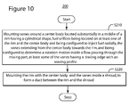
- a premixer (11) may be manufactured using method 200 whose flow chart is illustrated in Figure 9 .
- the method 200 includes mounting vanes (e.g., 175) around a center body (e.g., 170) located substantially in a middle of a rim (e.g., 150) having a cylindrical shape, the vanes (e.g., 175) extending from the center body (e.g., 170) towards the rim (e.g., 150), and being configured to determine a rotation motion inside a flow passing through the mixing part (e.g., 120), at least some of the vanes (e.g., 175) having a trailing edge (e.g., 177) with an waving profile.
- the method 200 further includes, at S220, mounting the rim (e.g., 150) with the center body (e.g., 170) and the vanes (e.g., 175) inside a shroud (e.g., 130), to form a duct (e.g., 144) between the rim (e.g., 150) and the shroud (e.g., 130), the rim (e.g., 150) having fuel orifices (e.g., 140) configured to enable fuel to be provided from the duct (e.g., 144) through the rim (e.g., 150) towards the center body (e.g., 170).
- a duct e.g., 144
- fuel orifices e.g., 140
- the method 200 may also include removing pre-existing vanes from the center body before mounting the vanes.
- a swirler of a conventional premixer e.g., 10
- a swirler of a conventional premixer can be modified into a swirler similar to the swirler 160.
- the disclosed exemplary embodiments provide a swirler useable in an aero-derivative engine on a gas and oil platform, the swirler having a simplified geometry compared with the conventional double annular swirler. It should be understood that this description is not intended to limit the invention. On the contrary, the exemplary embodiments are intended to cover alternatives, modifications and equivalents, which are included in the spirit and scope of the invention as defined by the appended claims. Further, in the detailed description of the exemplary embodiments, numerous specific details are set forth in order to provide a comprehensive understanding of the claimed invention. However, one skilled in the art would understand that various embodiments may be practiced without such specific details.
Landscapes
- Engineering & Computer Science (AREA)
- Chemical & Material Sciences (AREA)
- Combustion & Propulsion (AREA)
- Mechanical Engineering (AREA)
- General Engineering & Computer Science (AREA)
- Structures Of Non-Positive Displacement Pumps (AREA)
- Pyridine Compounds (AREA)
- Turbine Rotor Nozzle Sealing (AREA)
Abstract
Methods and devices useable in turbo-engines premixing of compressed air and fuel are provided. A premixer has a mixing part configured to receive a gas flow input in a flow direction and fluid fuel injected substantially perpendicular to the flow direction. The mixing part has a rim configured to define a substantially cylindrical shape. The mixing part also has a swirler with (i) a center body located substantially in a middle of the cylindrical shape along the flow direction, and (ii) a set of vanes extending from the center body towards the rim, the vanes being configured to determine a rotation motion inside a flow that includes the received gas flow and the injected fuel when the flow passes through the mixing part, at least some of the vanes having a trailing edge with a waving profile configured to generate mixing zones inside the flow thereafter.
Description
- Embodiments of the subject matter disclosed herein generally relate to methods and systems used to generate a substantially uniform compressed air-fuel mixture used in a turbo-compressor engine, and, more particularly, to a swirler having a set of vanes with sculpted trailing edges.
- Atmospheric pollution concerns have led worldwide to stricter emissions standards requiring significant reductions in gas turbine emissions, for industrial and power generation as well as propulsion applications. Nitrogen Oxides (NOx) are among the major pollutants produced by human activity. The NOx are generally formed in high temperature regions of flames in gas turbine engines. Lowering the flame temperatures leads to a reduction of the NOx emissions. For example,
Figure 1 is a graph illustrating the correlation between an amount of NOx emissions and the temperature of the flame. The amount of NOx on the y-axis of the graph is expressed in parts-per-million by volume (ppmvd) corrected for 15% O2. (For aircraft propulsion systems the similar NOx emissions are reported per mass unit of liquid fuel used.) The flame temperature on the x-axis is in Kelvin degrees (K). The points represent data taken over a wide range of test conditions, but illustrate the correlation between the amount of NOx emission and the flame temperature. - Well-established techniques of reducing a flame temperature include injecting high purity water or steam in a combustor and using a selective catalytic reduction. However, both these techniques, generically named wet low NOx techniques, require extensive use of ancillary equipment, which results in increasing the cost of energy production. Additionally, the space required for using these techniques is a problem in aero-derivative engines as well as in aircraft engines.
- Aero-derivative engines are frequently used on oil and gas platforms used for exploration and exploitation of subsea reservoirs. These engines may be seen as modified aircraft engines, which instead of being used for propulsion are used to generate mechanical drive for oil and gas pumps or as power generators. The aero-derivative engines are used on oil and gas platforms because of their high power and efficiency as well as compactness. The aero-derivative engines are typically modified to use natural gas as fuel (instead of liquid fuel), but liquid fuel could also be used as backup fuel.
- From a historical perspective, flames in engines used to be diffusion flames with a localized hot spots having adiabatic flame temperature. The diffusion flames yield NOx amounts of hundreds of ppm and are very stable. In contrast, some current pollution regulations require the amount of NOx to be no larger than 5 ppm.
- Another known method of reducing the temperature of the flame and consequently the NOx emissions is mixing uniformly fuel and compressed air before the burning. In a diffusion flame there are regions having different proportions of fuel and air, for example characterized by stoichiometry ratios of 0.1, 1, 2, and 5. In contrast, by using a premixer, a constant stoichiometry ratio of 0.5 may be achieved. In other words, the non-uniformity of the air-fuel mixture causes the flame to be locally hotter. Using a uniform mixture of fuel and compressed air technology is known as dry low NOx. A premixer which is traditionally placed between a compressor and a turbine may be configured to achieve a uniform mixture of compressed air and fuel. The premixer may be part of a combustor.
- An exploded view of a conventional aero-
derivative premixer 10 is illustrated inFigure 2 . The compressed air produced by a compressor flows into thepremixer 10 in aflow direction 15. Thepremixer 10 includes amixing part 20 and ashroud 30. The mixingpart 20 and theshroud 30 are configured to engage with each other. - The fuel is injected radially in the mixing
part 20 through fuel orifices (nozzles) 40 located on arim 50 of themixing part 20. Inside the mixingpart 20, a double annularcounter rotating swirler 60 has acenter body 70 and two sets ofvanes intermediate rim 85. Thevanes 80 form an inner swirler configured to direct a flow passing therethrough such as to generate an inner rotation in a plane perpendicular to theflow direction 15. Thevanes 90 form a counter-rotating swirler configured to direct a flow passing therethrough such as to generate an outer rotation in the plane perpendicular to theflow direction 15, the outer rotation being opposite to the inner rotation. Consequently, after passing through the double annularcounter rotating swirler 60, there are twoflows Figure 3 . A high turbulence occurs at the shear layer between the flows causing a rapid and uniform mixing of the compressed air and the fuel. As the two flows advance in the flow direction the mixing spreads radially from approximately a position of theintermediate rim 85 towards a center and an outside. - The double annular counter rotating
conventional swirler 60 has a complicated geometry, is expensive to manufacture and hard to control from a fluid dynamics perspective since turbulence is generally a violent unstable phenomenon. - Accordingly, it would be desirable to provide a cheaper premixer with improved performances.
- According to one exemplary embodiment, a premixer has a mixing part configured to receive a gas flow input in a flow direction and fluid fuel injected substantially perpendicularly to the flow direction. The mixing part includes a rim configured to define a substantially cylindrical shape and a swirler with (i) a center body located substantially in a middle of the cylindrical shape along the flow direction, and (ii) a set of vanes extending from the center body towards the rim, the vanes being configured to determine a rotation motion inside a flow that includes the received gas flow and the injected fuel when the flow passes through the mixing part, at least some of the vanes having a trailing edge with a waving profile configured to generate mixing zones inside the flow thereafter.
- According to another exemplary embodiment, a turbo-engine has a compressor configured to compress a gas flow passing therethrough, a turbine configured to receive a gaseous mixture flow, and a premixer located between the compressor and the turbine, and configured to mix the compressed gas exiting the compressor and fluid fuel to yield the gaseous mixture, and to output the gaseous mixture towards the turbine. The premixer has a mixing part configured to receive the compressed gas input in a flow direction and the fuel injected substantially perpendicular to the flow direction. The mixing part includes a rim configured to define a substantially cylindrical shape and a swirler with (i) a center body located substantially in a middle of the cylindrical shape along the flow direction, and (ii) a set of vanes extending from the center body towards the rim, the vanes being configured to determine a rotation motion inside the gaseous mixture, when the gaseous mixture passes through the mixing part. At least some of the vanes have a trailing edge with a waving profile configured to generate mixing zones inside the flow thereafter.
- According to another exemplary embodiment, a method of manufacturing a premixer is provided. The method includes mounting vanes around a center body located substantially in a middle of a rim having a cylindrical shape, , fuel orifices being located on at least one of the rim and the center body and being configured to inject fluid fuel radially. The vanes extend from the center body towards the rim, and are configured to determine a rotation motion inside a flow passing through the mixing part, at least some of the vanes having a trailing edge with a waving profile. The method further includes mounting the rim with the center body and the vanes inside a first end of a shroud, to form a duct between the rim and a second of the shroud.
- The accompanying drawings, which are incorporated in and constitute a part of the specification, illustrate one or more embodiments and, together with the description, explain these embodiments. In the drawings:
-
Figure 1 is a graph illustrating a correlation between an amount of NOx emissions and a temperature of a flame; -
Figure 2 is an exploded view of a conventional premixer; -
Figure 3 is a schematic illustration of rotation speeds inside a conventional premixer after a double annular swirl; -
Figure 4 is a schematic diagram of a turbo-engine according to an exemplary embodiment; -
Figure 5 is an exploded view of a premixer according to an exemplary embodiment; -
Figure 6 is a schematic illustration of rotation speeds in the premixer after a swirl according to an exemplary embodiment; -
Figure 7 is a schematic representation of a vane according to an exemplary embodiment; -
Figure 8 is a cross-section including a flow direction of a premixer according to an exemplary embodiment; -
Figure 9 is a schematic representation of a vane position relative to a flow direction according to an exemplary embodiment; and -
Figure 10 is a flow chart of a method for manufacturing a premixer according to an exemplary embodiment. - The following description of the exemplary embodiments refers to the accompanying drawings. The same reference numbers in different drawings identify the same or similar elements. The following detailed description does not limit the invention. Instead, the scope of the invention is defined by the appended claims. The following embodiments are discussed, for simplicity, with regard to the terminology and structure of premixers used in aero-derivative engines. However, the embodiments to be discussed next are not limited to these systems, but may be applied to other systems that require achieving a uniform mixture of gases.
- Reference throughout the specification to "one embodiment" or "an embodiment" means that a particular feature, structure, or characteristic described in connection with an embodiment is included in at least one embodiment of the subject matter disclosed. Thus, the appearance of the phrases "in one embodiment" or "in an embodiment" in various places throughout the specification is not necessarily referring to the same embodiment. Further, the particular features, structures or characteristics may be combined in any suitable manner in one or more embodiments.
- A turbo-engine 100 generally includes a
compressor 108, apremixer 110, and aturbine 112, as schematically represented inFigure 4 . Although asingle premixer 110 is illustrated and discussed hereinafter, it is known in the art that multiple premixers may be placed between thecompressor 108 and theturbine 112. Thepremixer 110 may be part of a combustor configured to initiate and host the flame, for example, in a combustion chamber. However, the burning may alternatively take place inside theturbine 112. An exact location of the burning is not relevant or limiting for the embodiments discussed hereinafter. Air or another gas including oxygen (for simplicity referred to as air in the following description) is compressed in the compressor 105, mixed with fuel received from asupply 114 in thepremixer 110, burned to generate hot, high-pressure gases which are then expanded in theturbine 112. InFigure 2 , transition from thecompressor 108 to thepremixer 110 and then to theturbine 112 are represented using dashed lines as other components may exist in-between. The fuel may be in a gaseous form (e.g., natural gas) or in a liquid form, and, thus, may be characterized as being fluid fuel. -
Figure 5 is an exploded view of thepremixer 110 according to an embodiment. The compressed air produced by thecompressor 108 enters thepremixer 110 along aflow direction 115. Thepremixer 110 includes a mixingpart 120 and ashroud 130 configured to engage with each other. For example, theshroud 130 may receive at least partially the mixingpart 120 therein. - The mixing
part 110 includes aswirler 160 having a simpler geometry than theconventional swirler 60, thereby, being easier and cheaper to manufacture. Thepremixer 110 also achieves better control of the flow dynamics and improved mixing efficiency compared to theconventional premixer 10. - The mixing
part 120 has a substantially cylindrical shape, theflow direction 115 being substantially parallel with a central axis of the cylindrical shape. Fuel is injected radially inside the mixingpart 120 through fuel orifices (nozzles) 140 located on arim 150 of the mixingpart 120. Inside the mixingpart 120, theswirler 160 has acenter body 170 located substantially in a middle of the cylindrical shape along the longitudinal axis of the cylindrical shape. A set ofvanes 175 is attached to and extending from thecenter body 170 towards therim 150. In one application, there is no additional set of vanes for premixing the fuel, i.e., the set of vanes is a single set of vanes. - The
fuel orifices 140 may be located at substantially equal distances around therim 150, between radial positions of the vanes. InFigure 6 , pairs offuel orifices 140 are located a predetermined distance in-between, at different positions in the flow direction. In alternative embodiments, the fuel may be injected from thecenter body 170 or both from thecenter body 170 and therim 150. Thus, the fuel is injected radially, while the compressed air flows longitudinally. - The
vanes 175 are configured to determine a rotation motion inside the flow passing through the mixingpart 120, each of thevanes 175 having a sculptedtrailing edge 177 configured to generate mixingzones 178 in which a rotation speed varies in the flow as illustrated inFigure 6 . Thus, a mixingzone 178 occurs behind each of thevanes 175 in theflow direction 115, the presence of these mixing zones causing a rapid and uniform mixing of the compressed air and the fuel. In contrast, to the turbulence occurring at a shear surface between counter-rotating flows after a conventional double annular swirl, in the present mixing zones are created variations of the rotating speeds favoring mixing but in a less violent manner. After theswirl 160, a mixing initiated in the mixing zones expands throughout the volume due to an ongoing rotation motion in the flow. -
Figure 7 illustrates one embodiment of avane 175 according to an exemplary embodiment. The vane is attached to thecenter body 170 on aside 179, theother side 174 facing therim 150. A leadingside 176 first encountered by the compressed air flow is smooth, while the trailingside 177 has a serpentine shape (i.e., waving profile) forming teeth extending in theflow direction 115. According to another embodiment, among neighboring teeth, one tooth (e.g., 181) may be bended upwards relative to the vane's plane, while a neighboring one may be bended downwards relative to the vane's plane. Theside 179 of the vane 175 (where the vane is attached to the center body) may be larger than theopposite side 174. Thevanes 175 may be manufactured using a direct laser manufacturing sintering (DLMS) method. Solidity or number of vanes per annulus area is according to current practice known in the art. -
Figure 8 is a cross-section of thepremixer 110 including theflow direction 115. Thevanes 175 may be attached at substantially equal radial distanced around thecenter body 170. A plane of an attachedvane 175 makes an angle α (less that 45°) with theflow direction 115 as detailed inFigure 9 . However, the vanes may have a more complex three-dimensional shape to have a varying angle relative to theflow direction 115. -
Fuel orifices 140 positioned at different locations along the flow direction between the same vanes may be arranged to mimic the vanes angle. For example, if only two nozzles are considered a line connecting the two nozzles makes the same angle with the flow direction as the plane of the vanes. - The
center body 170 extends inside aduct 135 inside theshroud 130. Due to the narrowing cross section of theduct 135 in theflow direction 115, the air-fuel mixture exiting the mixingpart 120 is accelerated. The resulting increase of the speed of the air-fuel mixture in theflow direction 115 achieves a desired objective, that is, keeping the flame outside theduct 135. - The fuel may be brought to the mixing
part 120 through apipe 142 and may fill aduct 144 formed between the mixingpart 120 and theshroud 130. - A premixer (11) may be manufactured using
method 200 whose flow chart is illustrated inFigure 9 . At S210, themethod 200 includes mounting vanes (e.g., 175) around a center body (e.g., 170) located substantially in a middle of a rim (e.g., 150) having a cylindrical shape, the vanes (e.g., 175) extending from the center body (e.g., 170) towards the rim (e.g., 150), and being configured to determine a rotation motion inside a flow passing through the mixing part (e.g., 120), at least some of the vanes (e.g., 175) having a trailing edge (e.g., 177) with an waving profile. Themethod 200, further includes, at S220, mounting the rim (e.g., 150) with the center body (e.g., 170) and the vanes (e.g., 175) inside a shroud (e.g., 130), to form a duct (e.g., 144) between the rim (e.g., 150) and the shroud (e.g., 130), the rim (e.g., 150) having fuel orifices (e.g., 140) configured to enable fuel to be provided from the duct (e.g., 144) through the rim (e.g., 150) towards the center body (e.g., 170). - The
method 200 may also include removing pre-existing vanes from the center body before mounting the vanes. In other words, a swirler of a conventional premixer (e.g., 10) can be modified into a swirler similar to theswirler 160. - The disclosed exemplary embodiments provide a swirler useable in an aero-derivative engine on a gas and oil platform, the swirler having a simplified geometry compared with the conventional double annular swirler. It should be understood that this description is not intended to limit the invention. On the contrary, the exemplary embodiments are intended to cover alternatives, modifications and equivalents, which are included in the spirit and scope of the invention as defined by the appended claims. Further, in the detailed description of the exemplary embodiments, numerous specific details are set forth in order to provide a comprehensive understanding of the claimed invention. However, one skilled in the art would understand that various embodiments may be practiced without such specific details.
- Although the features and elements of the present exemplary embodiments are described in the embodiments in particular combinations, each feature or element can be used alone without the other features and elements of the embodiments or in various combinations with or without other features and elements disclosed herein.
- This written description uses examples of the subject matter disclosed to enable any person skilled in the art to practice the same, including making and using any devices or systems and performing any incorporated methods. The patentable scope of the subject matter is defined by the claims, and may include other examples that occur to those skilled in the art. Such other examples are intended to be within the scope of the claims.
- Various aspects and embodiments of the present invention are defined by the following numbered clauses:
- 1. A premixer comprising:
- a mixing part configured to receive a gas flow input in a flow direction and fluid fuel injected substantially perpendicularly to the flow direction, the mixing part including:
- a rim configured to define a substantially cylindrical shape, and
- a swirler with (i) a center body located substantially in a middle of the cylindrical shape along the flow direction, and (ii) a set of vanes extending from the center body towards the rim, the vanes being configured to determine a rotation motion inside a flow that includes the received gas flow and the injected fuel when the flow passes through the mixing part, at least some of the vanes having a trailing edge with a waving profile configured to generate mixing zones inside the flow thereafter.
- a mixing part configured to receive a gas flow input in a flow direction and fluid fuel injected substantially perpendicularly to the flow direction, the mixing part including:
- 2. The premixer of
clause 1, wherein neighboring teeth formed by the waving profile are bent in opposite directions relative to a plane of the vane. - 3. The premixer of
clause 1 or clause 2, wherein each vane has a shape that narrows from the center body towards the rim. - 4. The premixer of any preceding clause, wherein the vanes are located at substantially equal angles around the center body.
- 5. The premixer of any preceding clause, wherein the vanes are attached to the center body to make a predetermined angle with the flow direction.
- 6. The premixer of any preceding clause, wherein at least two fuel orifices are located at different positions along the flow directions between neighboring vanes.
- 7. The premixer of any preceding clause, wherein
fuel is injected through fuel orifices located on at least one of the rim and center body. - 8. The premixer of any preceding clause, further comprising:
- a shroud configured to receive the mixing part, the shroud being located after the mixing part along the flow direction, and being configured to accelerate the flow exiting the mixing part.
- 9. The premixer of any preceding clause, wherein the shroud has an inner duct with a narrowing cross-section along the fluid flow direction.
- 10. The premixer of any preceding clause, wherein the center body extends into the shroud.
- 11. The premixer of any preceding clause, wherein the swirler includes only one set of vanes.
- 12. A turbo-engine, comprising:
- a compressor configured to compress a gas passing therethrough;
- a turbine configured to receive a gaseous mixture; and
- a premixer located between the compressor and the turbine, and configured to mix the compressed gas exiting the compressor and fluid fuel to yield the gaseous mixture, and to output the gaseous mixture towards the turbine, the premixer including a mixing part configured to receive the compressed gas input in a flow direction and the fuel injected substantially perpendicular to the flow direction, the mixing part including:
- a rim configured to define a substantially cylindrical shape, and
- a swirler with (i) a center body located substantially in a middle of the cylindrical shape along the flow direction, and (ii) a set of vanes extending from the center body towards the rim, the vanes being configured to determine a rotation motion inside the gaseous mixture, when the gaseous mixture passes through the mixing part, at least some of the vanes having a trailing edge with a waving profile configured to generate mixing zones inside the gaseous mixture flow thereafter.
- 13. The turbo-engine of any preceding clause, wherein the swirler includes only one set of vanes.
- 14. The turbo-engine of v, wherein neighboring teeth formed by the waving profile are bent in opposite directions relative to a plane of the vane.
- 15. The turbo-engine of any preceding clause, wherein each vane has a shape that narrows from the center body towards the rim.
- 16. The turbo-engine of any preceding clause, wherein the fuel is injected through fuel orifices located on at least one of the rim and the center body.
- 17. The turbo-engine of any preceding clause, wherein the vanes are attached to the center body to make a predetermined angle with the flow direction.
- 18. The turbo-engine of any preceding clause, wherein the turboengine is an aero-derivative engine.
- 19. A method of manufacturing a premixer, comprising:
- mounting vanes around a center body located substantially in a middle of a rim having a cylindrical shape, fuel orifices being located on at least one of the rim and the center body and being configured to inject fluid fuel radially, the vanes extending from the center body towards the rim, and being configured to determine a rotation motion inside a flow passing through the mixing part, at least some of the vanes having a trailing edge with a waving profile; and
- mounting the rim with the center body and the vanes inside a first end a shroud, to form a duct between the rim and a second end of the shroud.
- 20. The method of clause 19, further comprising:
- removing pre-existing vanes from the center body before mounting the vanes.
Claims (15)
- A premixer (110) comprising:a mixing part (120) configured to receive a gas flow input in a flow direction (115) and fluid fuel injected substantially perpendicularly to the flow direction (115), the mixing part (120) including:a rim (150) configured to define a substantially cylindrical shape, anda swirler (160) with (i) a center body (170) located substantially in a middle of the cylindrical shape along the flow direction (115), and (ii) a set of vanes (175) extending from the center body (170) towards the rim (150), the vanes (175) being configured to determine a rotation motion inside a flow that includes the received gas flow and the injected fuel when the flow passes through the mixing part (120), at least some of the vanes (175) having a trailing edge (177) with a waving profile configured to generate mixing zones (178) inside the flow thereafter.
- The premixer of claim 1, wherein neighboring teeth formed by the waving profile are bent in opposite directions relative to a plane of the vane.
- The premixer of claim 1 or claim 2, wherein each vane has a shape that narrows from the center body towards the rim.
- The premixer of any preceding claim, wherein the vanes are located at substantially equal angles around the center body.
- The premixer of any preceding claim, wherein the vanes are attached to the center body to make a predetermined angle with the flow direction.
- The premixer of any preceding claim, wherein at least two fuel orifices are located at different positions along the flow directions between neighboring vanes.
- The premixer of any preceding claim, wherein
fuel is injected through fuel orifices located on at least one of the rim and center body. - The premixer of any preceding claim, further comprising:a shroud configured to receive the mixing part, the shroud being located after the mixing part along the flow direction, and being configured to accelerate the flow exiting the mixing part.
- The premixer of any preceding claim, wherein the shroud has an inner duct with a narrowing cross-section along the fluid flow direction.
- The premixer of any preceding claim, wherein the center body extends into the shroud.
- The premixer of any preceding claim, wherein the swirler includes only one set of vanes.
- A turbo-engine (100), comprising:a compressor (108) configured to compress a gas passing therethrough;a turbine (112) configured to receive a gaseous mixture; anda premixer (110) located between the compressor (108) and the turbine (112), and configured to mix the compressed gas exiting the compressor (108) and fluid fuel to yield the gaseous mixture, and to output the gaseous mixture towards the turbine (112), the premixer (110) including a mixing part (120) configured to receive the compressed gas input in a flow direction (115) and the fuel injected substantially perpendicular to the flow direction (115), the mixing part (120) including:a rim (150) configured to define a substantially cylindrical shape, anda swirler (160) with (i) a center body (170) located substantially in a middle of the cylindrical shape along the flow direction (115), and (ii) a set of vanes (175) extending from the center body (170) towards the rim (150), the vanes (175) being configured to determine a rotation motion inside the gaseous mixture, when the gaseous mixture passes through the mixing part (120), at least some of the vanes (175) having a trailing edge (177) with a waving profile configured to generate mixing zones (178) inside the gaseous mixture flow thereafter.
- The turbo-engine of claim 12, wherein the swirler includes only one set of vanes.
- The turbo-engine of claim 12 or claim 13, wherein neighboring teeth formed by the waving profile are bent in opposite directions relative to a plane of the vane.
- A method (200) of manufacturing a premixer (110), comprising:mounting (S210) vanes (175) around a center body (170) located substantially in a middle of a rim (150) having a cylindrical shape, fuel orifices (140) being located on at least one of the rim (150) and the center body (170) and being configured to inject fluid fuel radially, the vanes (175) extending from the center body (170) towards the rim (150), and being configured to determine a rotation motion inside a flow passing through the mixing part (120), at least some of the vanes (175) having a trailing edge (177) with a waving profile; andmounting (S220) the rim (150) with the center body (170) and the vanes (175) inside a first end a shroud (130), to form a duct (144) between the rim (150) and a second end of the shroud (130).
Applications Claiming Priority (1)
| Application Number | Priority Date | Filing Date | Title |
|---|---|---|---|
| ITCO2010A000069A IT1403221B1 (en) | 2010-12-30 | 2010-12-30 | PREMIXER OF Vortex COMBUSTION WITH EDWING EDGE AND METHOD |
Publications (1)
| Publication Number | Publication Date |
|---|---|
| EP2472182A2 true EP2472182A2 (en) | 2012-07-04 |
Family
ID=43736826
Family Applications (1)
| Application Number | Title | Priority Date | Filing Date |
|---|---|---|---|
| EP11194559A Withdrawn EP2472182A2 (en) | 2010-12-30 | 2011-12-20 | Sculpted trailing edge swirler combustion premixer and method |
Country Status (8)
| Country | Link |
|---|---|
| US (1) | US20120167570A1 (en) |
| EP (1) | EP2472182A2 (en) |
| JP (1) | JP6001848B2 (en) |
| KR (1) | KR20120078636A (en) |
| CN (1) | CN102563703B (en) |
| CA (1) | CA2762579A1 (en) |
| IT (1) | IT1403221B1 (en) |
| RU (1) | RU2011153547A (en) |
Cited By (1)
| Publication number | Priority date | Publication date | Assignee | Title |
|---|---|---|---|---|
| EP2505808A3 (en) * | 2011-03-28 | 2017-04-26 | Rolls-Royce Deutschland Ltd & Co KG | Device for mixing fuel and air of a turbojet engine |
Families Citing this family (10)
| Publication number | Priority date | Publication date | Assignee | Title |
|---|---|---|---|---|
| CN103629696B (en) * | 2012-08-24 | 2015-09-09 | 中航商用航空发动机有限责任公司 | A kind of combustion chamber fuel oil sprays and mixing arrangement and combustion chamber thereof |
| JP6430756B2 (en) | 2014-09-19 | 2018-11-28 | 三菱日立パワーシステムズ株式会社 | Combustion burner and combustor, and gas turbine |
| JP5913503B2 (en) * | 2014-09-19 | 2016-04-27 | 三菱重工業株式会社 | Combustion burner and combustor, and gas turbine |
| CN106958813B (en) * | 2017-03-20 | 2019-09-24 | 中国科学院工程热物理研究所 | A kind of swirler blades, nozzle, nozzle array and burner |
| CN110748887B (en) * | 2017-06-27 | 2021-11-09 | 珠海优特智厨科技有限公司 | Gas equipment |
| CN108592083B (en) * | 2018-05-09 | 2020-04-21 | 中国航发湖南动力机械研究所 | Combustion chamber adopting variable cross-section air inlet and multi-stage fuel supply and control method thereof |
| CN111520750B (en) * | 2020-03-25 | 2022-05-20 | 西北工业大学 | Novel combustion chamber head oil injection structure |
| CA3102511A1 (en) | 2020-12-11 | 2022-06-11 | De.Mission Inc. | Combustion burner with fixed vanes |
| US12181151B2 (en) | 2021-07-29 | 2024-12-31 | General Electric Company | Mixer vanes having a waveform profile |
| CN120331986B (en) * | 2025-06-19 | 2025-09-05 | 成都安美科能源管理有限公司 | An adaptively regulated high-efficiency gas mixing control device for LPG generator sets |
Family Cites Families (17)
| Publication number | Priority date | Publication date | Assignee | Title |
|---|---|---|---|---|
| JPH04126921A (en) * | 1990-09-19 | 1992-04-27 | Hitachi Ltd | Premix-type gas turbine combustor |
| US5251447A (en) * | 1992-10-01 | 1993-10-12 | General Electric Company | Air fuel mixer for gas turbine combustor |
| US5638682A (en) * | 1994-09-23 | 1997-06-17 | General Electric Company | Air fuel mixer for gas turbine combustor having slots at downstream end of mixing duct |
| JPH08145361A (en) * | 1994-11-16 | 1996-06-07 | Ishikawajima Harima Heavy Ind Co Ltd | Fuel injection valve for gas turbine |
| US5778676A (en) * | 1996-01-02 | 1998-07-14 | General Electric Company | Dual fuel mixer for gas turbine combustor |
| US5899075A (en) * | 1997-03-17 | 1999-05-04 | General Electric Company | Turbine engine combustor with fuel-air mixer |
| US6141967A (en) * | 1998-01-09 | 2000-11-07 | General Electric Company | Air fuel mixer for gas turbine combustor |
| JP3970244B2 (en) * | 2001-07-10 | 2007-09-05 | 三菱重工業株式会社 | Premixing nozzle and combustor and gas turbine |
| FR2855558B1 (en) * | 2003-05-28 | 2005-07-15 | Snecma Moteurs | TURBOMACHINE TUBE WITH NOISE REDUCTION |
| US6968693B2 (en) * | 2003-09-22 | 2005-11-29 | General Electric Company | Method and apparatus for reducing gas turbine engine emissions |
| JP4486549B2 (en) * | 2005-06-06 | 2010-06-23 | 三菱重工業株式会社 | Gas turbine combustor |
| JP4476177B2 (en) * | 2005-06-06 | 2010-06-09 | 三菱重工業株式会社 | Gas turbine combustion burner |
| JP4719059B2 (en) * | 2006-04-14 | 2011-07-06 | 三菱重工業株式会社 | Gas turbine premixed combustion burner |
| US20080276622A1 (en) * | 2007-05-07 | 2008-11-13 | Thomas Edward Johnson | Fuel nozzle and method of fabricating the same |
| US20100180599A1 (en) * | 2009-01-21 | 2010-07-22 | Thomas Stephen R | Insertable Pre-Drilled Swirl Vane for Premixing Fuel Nozzle |
| US20100322774A1 (en) * | 2009-06-17 | 2010-12-23 | Morrison Jay A | Airfoil Having an Improved Trailing Edge |
| US9429074B2 (en) * | 2009-07-10 | 2016-08-30 | Rolls-Royce Plc | Aerodynamic swept vanes for fuel injectors |
-
2010
- 2010-12-30 IT ITCO2010A000069A patent/IT1403221B1/en active
-
2011
- 2011-12-16 US US13/328,827 patent/US20120167570A1/en not_active Abandoned
- 2011-12-20 JP JP2011278144A patent/JP6001848B2/en not_active Expired - Fee Related
- 2011-12-20 EP EP11194559A patent/EP2472182A2/en not_active Withdrawn
- 2011-12-22 CA CA2762579A patent/CA2762579A1/en not_active Abandoned
- 2011-12-28 RU RU2011153547/06A patent/RU2011153547A/en not_active Application Discontinuation
- 2011-12-29 KR KR1020110146291A patent/KR20120078636A/en not_active Ceased
- 2011-12-30 CN CN201110461890.2A patent/CN102563703B/en not_active Expired - Fee Related
Non-Patent Citations (1)
| Title |
|---|
| None |
Cited By (1)
| Publication number | Priority date | Publication date | Assignee | Title |
|---|---|---|---|---|
| EP2505808A3 (en) * | 2011-03-28 | 2017-04-26 | Rolls-Royce Deutschland Ltd & Co KG | Device for mixing fuel and air of a turbojet engine |
Also Published As
| Publication number | Publication date |
|---|---|
| JP6001848B2 (en) | 2016-10-05 |
| RU2011153547A (en) | 2013-07-10 |
| KR20120078636A (en) | 2012-07-10 |
| ITCO20100069A1 (en) | 2012-07-01 |
| CA2762579A1 (en) | 2012-06-30 |
| CN102563703A (en) | 2012-07-11 |
| IT1403221B1 (en) | 2013-10-17 |
| JP2012141122A (en) | 2012-07-26 |
| US20120167570A1 (en) | 2012-07-05 |
| CN102563703B (en) | 2015-11-25 |
Similar Documents
| Publication | Publication Date | Title |
|---|---|---|
| EP2472182A2 (en) | Sculpted trailing edge swirler combustion premixer and method | |
| US9284888B2 (en) | System for supplying fuel to late-lean fuel injectors of a combustor | |
| US8973368B2 (en) | Mixer assembly for a gas turbine engine | |
| US10718524B2 (en) | Mixer assembly for a gas turbine engine | |
| US9528704B2 (en) | Combustor cap having non-round outlets for mixing tubes | |
| EP2639507A2 (en) | System for supplying a working fluid to a combustor | |
| US9027324B2 (en) | Engine and combustion system | |
| US20120058437A1 (en) | Apparatus and method for mixing fuel in a gas turbine nozzle | |
| EP2801761B1 (en) | Method of configuring a combustor | |
| US20180372318A1 (en) | Combustor | |
| CN120777101A (en) | Gas turbine engine and fuel nozzle assembly thereof | |
| CN119737632A (en) | Combustion section with primary combustion chamber and secondary combustion chamber | |
| CN117917529A (en) | Gas turbine engine combustor with dilution passages | |
| CN118224615A (en) | Gas turbine engine combustor having a set of dilution passages | |
| US20250362020A1 (en) | Gas turbine engine and fuel nozzle assembly therefor | |
| US12429222B2 (en) | Flex fuel combustor | |
| EP4722596A1 (en) | Gas turbine engine and fuel injector assembly therefor | |
| US20250109853A1 (en) | Combustion section with a primary combustor and a set of secondary combustors | |
| JP2020165399A (en) | Combustor, combustor system, and gas turbine system | |
| CN119687479A (en) | Combustion section with primary burner and a set of secondary burners | |
| CN119146450A (en) | Combustion section with primary burner and a set of secondary burners |
Legal Events
| Date | Code | Title | Description |
|---|---|---|---|
| AK | Designated contracting states |
Kind code of ref document: A2 Designated state(s): AL AT BE BG CH CY CZ DE DK EE ES FI FR GB GR HR HU IE IS IT LI LT LU LV MC MK MT NL NO PL PT RO RS SE SI SK SM TR |
|
| AX | Request for extension of the european patent |
Extension state: BA ME |
|
| PUAI | Public reference made under article 153(3) epc to a published international application that has entered the european phase |
Free format text: ORIGINAL CODE: 0009012 |
|
| STAA | Information on the status of an ep patent application or granted ep patent |
Free format text: STATUS: THE APPLICATION IS DEEMED TO BE WITHDRAWN |
|
| 18D | Application deemed to be withdrawn |
Effective date: 20170701 |