EP2472143A1 - Multi-shaft drive device - Google Patents
Multi-shaft drive device Download PDFInfo
- Publication number
- EP2472143A1 EP2472143A1 EP10812013A EP10812013A EP2472143A1 EP 2472143 A1 EP2472143 A1 EP 2472143A1 EP 10812013 A EP10812013 A EP 10812013A EP 10812013 A EP10812013 A EP 10812013A EP 2472143 A1 EP2472143 A1 EP 2472143A1
- Authority
- EP
- European Patent Office
- Prior art keywords
- output
- drive device
- input
- gear
- shaft
- Prior art date
- Legal status (The legal status is an assumption and is not a legal conclusion. Google has not performed a legal analysis and makes no representation as to the accuracy of the status listed.)
- Withdrawn
Links
Images








Classifications
-
- F—MECHANICAL ENGINEERING; LIGHTING; HEATING; WEAPONS; BLASTING
- F16—ENGINEERING ELEMENTS AND UNITS; GENERAL MEASURES FOR PRODUCING AND MAINTAINING EFFECTIVE FUNCTIONING OF MACHINES OR INSTALLATIONS; THERMAL INSULATION IN GENERAL
- F16H—GEARING
- F16H1/00—Toothed gearings for conveying rotary motion
- F16H1/02—Toothed gearings for conveying rotary motion without gears having orbital motion
- F16H1/04—Toothed gearings for conveying rotary motion without gears having orbital motion involving only two intermeshing members
- F16H1/12—Toothed gearings for conveying rotary motion without gears having orbital motion involving only two intermeshing members with non-parallel axes
- F16H1/14—Toothed gearings for conveying rotary motion without gears having orbital motion involving only two intermeshing members with non-parallel axes comprising conical gears only
-
- B—PERFORMING OPERATIONS; TRANSPORTING
- B60—VEHICLES IN GENERAL
- B60N—SEATS SPECIALLY ADAPTED FOR VEHICLES; VEHICLE PASSENGER ACCOMMODATION NOT OTHERWISE PROVIDED FOR
- B60N2/00—Seats specially adapted for vehicles; Arrangement or mounting of seats in vehicles
- B60N2/02—Seats specially adapted for vehicles; Arrangement or mounting of seats in vehicles the seat or part thereof being movable, e.g. adjustable
- B60N2/0296—Central command actuator to selectively switch on or engage one of several special purpose circuits or mechanisms
-
- B—PERFORMING OPERATIONS; TRANSPORTING
- B60—VEHICLES IN GENERAL
- B60N—SEATS SPECIALLY ADAPTED FOR VEHICLES; VEHICLE PASSENGER ACCOMMODATION NOT OTHERWISE PROVIDED FOR
- B60N2/00—Seats specially adapted for vehicles; Arrangement or mounting of seats in vehicles
- B60N2/02—Seats specially adapted for vehicles; Arrangement or mounting of seats in vehicles the seat or part thereof being movable, e.g. adjustable
- B60N2/0224—Non-manual adjustments, e.g. with electrical operation
- B60N2/02246—Electric motors therefor
-
- B—PERFORMING OPERATIONS; TRANSPORTING
- B60—VEHICLES IN GENERAL
- B60N—SEATS SPECIALLY ADAPTED FOR VEHICLES; VEHICLE PASSENGER ACCOMMODATION NOT OTHERWISE PROVIDED FOR
- B60N2/00—Seats specially adapted for vehicles; Arrangement or mounting of seats in vehicles
- B60N2/02—Seats specially adapted for vehicles; Arrangement or mounting of seats in vehicles the seat or part thereof being movable, e.g. adjustable
- B60N2/04—Seats specially adapted for vehicles; Arrangement or mounting of seats in vehicles the seat or part thereof being movable, e.g. adjustable the whole seat being movable
- B60N2/06—Seats specially adapted for vehicles; Arrangement or mounting of seats in vehicles the seat or part thereof being movable, e.g. adjustable the whole seat being movable slidable
-
- B—PERFORMING OPERATIONS; TRANSPORTING
- B60—VEHICLES IN GENERAL
- B60N—SEATS SPECIALLY ADAPTED FOR VEHICLES; VEHICLE PASSENGER ACCOMMODATION NOT OTHERWISE PROVIDED FOR
- B60N2/00—Seats specially adapted for vehicles; Arrangement or mounting of seats in vehicles
- B60N2/02—Seats specially adapted for vehicles; Arrangement or mounting of seats in vehicles the seat or part thereof being movable, e.g. adjustable
- B60N2/04—Seats specially adapted for vehicles; Arrangement or mounting of seats in vehicles the seat or part thereof being movable, e.g. adjustable the whole seat being movable
- B60N2/16—Seats specially adapted for vehicles; Arrangement or mounting of seats in vehicles the seat or part thereof being movable, e.g. adjustable the whole seat being movable height-adjustable
-
- F—MECHANICAL ENGINEERING; LIGHTING; HEATING; WEAPONS; BLASTING
- F16—ENGINEERING ELEMENTS AND UNITS; GENERAL MEASURES FOR PRODUCING AND MAINTAINING EFFECTIVE FUNCTIONING OF MACHINES OR INSTALLATIONS; THERMAL INSULATION IN GENERAL
- F16H—GEARING
- F16H25/00—Gearings comprising primarily only cams, cam-followers and screw-and-nut mechanisms
- F16H25/16—Gearings comprising primarily only cams, cam-followers and screw-and-nut mechanisms for interconverting rotary motion and oscillating motion
-
- F—MECHANICAL ENGINEERING; LIGHTING; HEATING; WEAPONS; BLASTING
- F16—ENGINEERING ELEMENTS AND UNITS; GENERAL MEASURES FOR PRODUCING AND MAINTAINING EFFECTIVE FUNCTIONING OF MACHINES OR INSTALLATIONS; THERMAL INSULATION IN GENERAL
- F16H—GEARING
- F16H37/00—Combinations of mechanical gearings, not provided for in groups F16H1/00 - F16H35/00
- F16H37/02—Combinations of mechanical gearings, not provided for in groups F16H1/00 - F16H35/00 comprising essentially only toothed or friction gearings
- F16H37/06—Combinations of mechanical gearings, not provided for in groups F16H1/00 - F16H35/00 comprising essentially only toothed or friction gearings with a plurality of driving or driven shafts; with arrangements for dividing torque between two or more intermediate shafts
- F16H37/065—Combinations of mechanical gearings, not provided for in groups F16H1/00 - F16H35/00 comprising essentially only toothed or friction gearings with a plurality of driving or driven shafts; with arrangements for dividing torque between two or more intermediate shafts with a plurality of driving or driven shafts
-
- F—MECHANICAL ENGINEERING; LIGHTING; HEATING; WEAPONS; BLASTING
- F16—ENGINEERING ELEMENTS AND UNITS; GENERAL MEASURES FOR PRODUCING AND MAINTAINING EFFECTIVE FUNCTIONING OF MACHINES OR INSTALLATIONS; THERMAL INSULATION IN GENERAL
- F16H—GEARING
- F16H63/00—Control outputs from the control unit to change-speed- or reversing-gearings for conveying rotary motion or to other devices than the final output mechanism
- F16H63/02—Final output mechanisms therefor; Actuating means for the final output mechanisms
- F16H63/30—Constructional features of the final output mechanisms
- F16H63/304—Constructional features of the final output mechanisms the final output mechanisms comprising elements moved by electrical or magnetic force
- F16H2063/3056—Constructional features of the final output mechanisms the final output mechanisms comprising elements moved by electrical or magnetic force using cam or crank gearing
-
- F—MECHANICAL ENGINEERING; LIGHTING; HEATING; WEAPONS; BLASTING
- F16—ENGINEERING ELEMENTS AND UNITS; GENERAL MEASURES FOR PRODUCING AND MAINTAINING EFFECTIVE FUNCTIONING OF MACHINES OR INSTALLATIONS; THERMAL INSULATION IN GENERAL
- F16H—GEARING
- F16H63/00—Control outputs from the control unit to change-speed- or reversing-gearings for conveying rotary motion or to other devices than the final output mechanism
- F16H63/02—Final output mechanisms therefor; Actuating means for the final output mechanisms
- F16H63/30—Constructional features of the final output mechanisms
- F16H63/304—Constructional features of the final output mechanisms the final output mechanisms comprising elements moved by electrical or magnetic force
-
- Y—GENERAL TAGGING OF NEW TECHNOLOGICAL DEVELOPMENTS; GENERAL TAGGING OF CROSS-SECTIONAL TECHNOLOGIES SPANNING OVER SEVERAL SECTIONS OF THE IPC; TECHNICAL SUBJECTS COVERED BY FORMER USPC CROSS-REFERENCE ART COLLECTIONS [XRACs] AND DIGESTS
- Y10—TECHNICAL SUBJECTS COVERED BY FORMER USPC
- Y10T—TECHNICAL SUBJECTS COVERED BY FORMER US CLASSIFICATION
- Y10T74/00—Machine element or mechanism
- Y10T74/19—Gearing
- Y10T74/19023—Plural power paths to and/or from gearing
- Y10T74/19051—Single driven plural drives
-
- Y—GENERAL TAGGING OF NEW TECHNOLOGICAL DEVELOPMENTS; GENERAL TAGGING OF CROSS-SECTIONAL TECHNOLOGIES SPANNING OVER SEVERAL SECTIONS OF THE IPC; TECHNICAL SUBJECTS COVERED BY FORMER USPC CROSS-REFERENCE ART COLLECTIONS [XRACs] AND DIGESTS
- Y10—TECHNICAL SUBJECTS COVERED BY FORMER USPC
- Y10T—TECHNICAL SUBJECTS COVERED BY FORMER US CLASSIFICATION
- Y10T74/00—Machine element or mechanism
- Y10T74/19—Gearing
- Y10T74/19219—Interchangeably locked
- Y10T74/19251—Control mechanism
-
- Y—GENERAL TAGGING OF NEW TECHNOLOGICAL DEVELOPMENTS; GENERAL TAGGING OF CROSS-SECTIONAL TECHNOLOGIES SPANNING OVER SEVERAL SECTIONS OF THE IPC; TECHNICAL SUBJECTS COVERED BY FORMER USPC CROSS-REFERENCE ART COLLECTIONS [XRACs] AND DIGESTS
- Y10—TECHNICAL SUBJECTS COVERED BY FORMER USPC
- Y10T—TECHNICAL SUBJECTS COVERED BY FORMER US CLASSIFICATION
- Y10T74/00—Machine element or mechanism
- Y10T74/19—Gearing
- Y10T74/19219—Interchangeably locked
- Y10T74/19251—Control mechanism
- Y10T74/19279—Cam operated
Definitions
- the present invention relates to a multi-shaft drive device in which plural output shafts are driven by one motor which is desirably used for, for example, electrical seats for vehicles or the like.
- seats for vehicles there are many features having parts of which plural positions can be adjusted (for example, front-back direction slide of entire seat, up-and-down motion of seating face height, or reclining of seatback (backrest) can be adjusted) in accordance with body type or position of a passenger.
- the adjustments of these movable parts have been manually performed, but electrical seats, which are adjusted by motor drive, are provided as more useful seats.
- an electrical seat In order to drive plural movable parts independently, an electrical seat is thought of as having a structure in which one motor is connected to each output shaft connected to the movable parts. However, the number of motors is increased. Therefore, it is efficient to drive plural output shafts by one motor. In order to realize this, it is known that motor power is transmitted to each output shaft, which is connected to plural movable parts, via a clutch, and the clutch is connected or disconnected and each movable part is selectively driven (see Patent Documents 1 to 4).
- An object of the present invention is to provide a multi-shaft drive device which can perform weight reduction and space reduction by using a mechanical clutch having a simplified structure for driving plural output shafts by one motor.
- a multi-shaft drive device includes: an input member which is connected to a rotational shaft of a motor; plural output members which have an output shaft and are engageably provided to the input member, and to which rotation of the input member is transmitted when engaging with the input member; a selector member which is provided between the plural output members and has an action portion, the selector member being activated, the action portion facing one of the output members and acting thereon, thereby moving the one of the output members toward the input member and selectively engaging the one of the output members with the input member; and a rotary operational member which is connected to the selector member, the operational member being rotated so that selector member is activated.
- the selector member is rotated by the operational member, the action portion faces one of the output members, and the output member is moved toward the input member, and the output member engages with the input member.
- the rotation of the input member can be transmitted to the output member.
- the action portion of the selector member may be a recess or a projection which is formed on a facing surface of the selector member which faces the output member.
- the action portion of the selector member may be provided in a condition of plural steps in a direction perpendicular to an activating direction of the selector member.
- many output shafts can be arranged in accordance with the number of steps of the cam surface, and more output shafts can be provided in the device.
- facing angle of the output shaft with respect to the action portion may be freely selected.
- the output member can be disposed in accordance with the extending direction of the desirable output member.
- the action portion may be the recess, and the output member may have a projection which projects from a front end surface of the output member and enters the recess.
- the action portion may be the projection, and the output member may be pressed by the projection.
- the output member may have a bevel gear
- the input member may have a bevel gear of which an axis crosses an axis of the bevel gear of the output member and engages with the bevel gear of the output member.
- the input member may be a spur gear to which rotation of the motor is transmitted
- the output member may have a spur gear which engages with the spur gear of the input member
- action mode of the selector member may be rotation or linear movement.
- the multi-shaft drive device may have a biasing means which biases the output member toward the input member; and the selector member may have a peripheral portion and the recess, wherein the peripheral portion may have a cylindrical curved surface and may allow the output member to be apart from the input member by contacting the output member, and the recess may be provided at the peripheral portion and may allow the output member to enter the recess and to be moved toward the input member.
- the recess may face the output member by rotation of the selector member, so that the output member may be moved by the biasing force of the biasing means, and may engage with the input member.
- a projection can be provided instead of the recess. That is, the multi-shaft drive device may have a biasing means which biases the output member in a direction in which the output member is apart from the input member, and the selector member may have a peripheral portion and the projection, the peripheral portion may have a cylindrical curved surface and may allow the output member to be apart from the input member by contacting the output member, the projection may be provided at the peripheral portion, and may press the output member and may thereby move the output member toward the input member.
- the output member can be engaged with the input member.
- the input member can consist of one gear.
- the input member may have: a first input gear which is connected to the rotational shaft of the motor; and plural second input gears which are provided at a peripheral side of the first input gear, wherein the second input gear may have: a first gear portion which engages with a peripheral portion of the first input gear; and a second gear portion which removably engages with the output member.
- the output member can be engaged with the second gear portion from an arbitrary direction, freedom of design can be increased as described hereinafter.
- the output member can be freely positioned along a circle of which center is an axis of the second input gear. It is desirable that the second input gear can be freely positioned along a circle of which center is an axis of the first input gear.
- the position and the angle of the output member can be appropriately changed in accordance with the position of the member to which the output member is connected or the like.
- the linear movement of the selector member may be performed by a rack and pinion mechanism provided between the selector member and the operational member.
- the multi-shaft drive device may have a biasing means which biases the output member toward the input member and the selector member may have a cam surface and the recess, the cam surface may allow the output member to be apart from the input member by contacting the output member, and the recess may be provided at the cam surface and may allow the output member to enter the recess and to be moved toward the input member.
- the output member enters the recess click feeling can be obtained, so that the operability and the feeling of operation may be good.
- the multi-shaft drive device may have a biasing means which biases the output member in a direction in which the output member is apart from the input member
- the selector member may have a cam surface and the recess, the cam surface may allow the output member to be apart from the input member by contacting the output member, the projection may be provided at the cam surface, and may press the output member and may thereby move the output member toward the input member.
- the multi-shaft drive device may have a stopper means which controls a movement range of the selector member. In this embodiment, removal of the output member from the cam surface can be prevented.
- multi-shaft drive device may use a feature in which a movable portion of a predetermined movable mechanism is connected to the output member, a switch which activates the motor is slidably provided at the operational member, the switch is slid in one direction, and the motor is thereby rotated in a normal direction, and the switch is slid in a direction opposite to the one direction, and the motor is thereby rotated in a reverse direction, and slide direction of the switch corresponds to a movable direction of the movable portion.
- the movable mechanism can be a vehicle seat.
- the output member may be connected to an adjustment mechanism of the movable portion of the vehicle seat.
- the feeling of operation corresponds to the actual movement, and there is an advantage that the multi-shaft drive device is thereby easily used.
- the mechanism for selectively providing the power of the motor to the plural output members and the selection of the output member to be activated are obtained by a compact structure, weight reduction and space reduction can be performed.
- Reference numerals 10, 140, and 200 denote a motor, 11,141, and 201 denote a motor shaft (rotational shaft of motor), 12 denotes a first input gear (spur gear), 14 denotes a second input gear (input member), 14a denotes a spur gear portion (first gear portion), 14b denotes a bevel gear portion (second gear portion), 21 denotes an output gear (output member), 22, 25, 62, and 72 denote an output shaft (output member), 23 and 133 denote a coil spring (biasing means), 24 denotes a pin (projection), 30 and 120 denote a dial (operational member), 41 denotes a cam (selector member), 42, 112, 233, 243, 253, 263, 273, and 283 denote a recess (action portion), 50 denotes a switch, 61 denotes an output gear (output member), 110, 230, 240, 250, 260, 270, and 280 denote a cam member (s
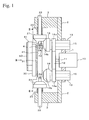
- Figs. 1 to 4C show a multi-shaft drive device of the first embodiment.
- this multi-shaft drive device is desirably constructed such that three movable mechanisms of vehicle electrical seat (electrical seat used for vehicles) are activated by one motor 10 which rotates in a normal direction and an opposite direction.
- the three movable mechanisms are a mechanism which adjusts seating face height, a mechanism which adjusts an angle of seat backrest section, and a mechanism which adjusts a front-back position of seat.
- the power of the motor 10 is selectively provided so as to activate the movable mechanisms.
- the motor 10 is fixed to a main frame 1 having a circular plate-shape.
- a first input gear 12 is fixed at a leading end of the motor shaft 11.
- Three bearings 13 are disposed around the motor 10 in a concentric pattern of which center is positioned at the motor 10.
- Shafts 15 of second input gears (input members) 14 are rotatably supported by the bearings 13.
- the second input gears 14 have spur gear portions (first gear portions) 14a and bevel gear portions (second gear portions) 14b.
- the spur gear portion 14a engages with the first input gear 12.
- the bevel gear portion 14b is positioned apart a predetermined distance from the spur gear portion 14a.
- the three second input gears 14 are positioned such that each rotational center of the three second input gears 14 is positioned at a vertex of an isosceles triangle.
- a rectangular plate-shaped subframe 2 is provided on the main frame 1. An end portion of the subframe 2 is cut to have a semicircular shape, and the end portion is fitted into a side surface of the bearing 13. The subframe 2 is rotated around the bearing 13, so that the subframe 2 can be positioned and fixed at a desired position.
- Bearing blocks 3 are provided on a surface of the subframe 2, and output shafts 22 of output gears (output members) 21 are rotatably supported by the bearing blocks 3.
- the output gear 21 is a bevel gear which can engage with the bevel gear portion 14b of the second input gear 14, and the output gear 21 is biased toward the leading end side thereof (the side of the bevel gear portion 14b) by a coil spring 23.
- a pin 24 projecting toward the leading end side is integrally formed at a center of front end surface of the output gear 21. The leading end of the pin 24 is formed to have a hemispherical shape.
- reference numeral 30 denotes a circular plate-shaped dial (operational member).
- the dial 30 has a rotational shaft 31 at a center thereof.
- the rotational shaft 31 extends coaxially with the motor shaft 11 and is rotatably supported by a frame 4.
- a cam (selector member) 41 is fixed at an end portion of the rotational shaft 31.
- the cam 41 has a circular plate-shape, and recesses 42 having a roughly trapezoidal shape are formed at a peripheral portion thereof.
- the pin 24 of one of the output gears 21 is projected toward the leading side thereof by the coil spring 23, thereby entering the recess 42, and the output gear 21 engages with the bevel gear portion 14b of the second input gear 14.
- the rotation of the motor 10 is transmitted from the first input gear 12 and the second input gear 14 to the output shaft 22 through the output gear 21.
- the pins 24 of the other two output gears 21 abut to a peripheral surface of the cam 41, and the output gear 21 is apart from the bevel gear portion 14b of the second input gear 14.
- the pin 24 of the output gear 21 which is positioned to have an apex angle of isosceles triangle, enters the recess 42.
- centers of the other two recesses 42 are positioned at points inclined at predetermined angle ⁇ (45 degrees in this embodiment) from each straight line.
- the rotation of the cam 41 is performed by rotation of the dial 30.
- the pin 24 enters the recess 42, so that click feeling in operation can be obtained, and the dial 30 can be reliably positioned at a connection position of the output gear 21.
- a switch 50 having a rectangular parallelepiped shape is provided at a surface of the dial 30, and the switch 50 is used for selection of ON/OFF and rotational direction of the motor 10.
- the switch 50 slides toward both sides of longitudinal direction (C-D direction in Fig. 3 ), and the switch 50 is controlled so as to stop at a middle point of slide range by a biasing member (not shown in the Figures).
- the switch 50 extends so as to pass through the center point of the dial 30, and one end portion of the switch 50 projects from the dial 30 and is positioned at the outside thereof.
- the projection end of the switch 50 is used as an indication portion 51.
- the switch 50 is provided to the dial 30 such that the indication portion 51 is inclined at 45 degrees from a center line of the pin 24 in a counterclockwise direction.
- the motor 10 When the switch 50 is positioned at the middle point in the stop condition in which the switch 50 does not move in a longitudinal direction, the motor 10 is in a power-off condition. For example, when the switch 50 slides in the C direction, the motor 10 rotates in a normal direction. For example, when the switch 50 slides in the D direction, the motor 10 rotates in an opposite direction. In this manner, the motor 10 is driven.
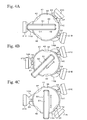
- the multi-shaft drive device of the first embodiment has the above structure. Next, an example in which the multi-shaft drive device is used for vehicle electric seat will be explained with reference to Figs. 4A to 4C .
- the multi-shaft drive device is provided at a position on a side surface of seat cushion, and th position allows a passenger, who sits on the seat cushion, to operate the dial 30.
- the motor shaft 11 extends in right and left direction of vehicle body
- the second input gear 14 positioned to have an apex angle of the isosceles triangle is positioned in the travel direction of the vehicle, and the other second input gears 14 are arranged at upper side and lower side of rear side of the vehicle.
- the second input gear 14 positioned at the front side is a front side second input gear 14A
- the second input gear 14 positioned at the lower side is a lower side second input gear 14B
- the second input gear 14 positioned at the upper side is an upper side second input gear 14C.
- the output gear 21 positioned at the front side is a front side output gear 21A
- the output gear 21 positioned at the lower side is a lower side output gear 21B
- the output gear 21 positioned at the upper side is an upper side output gear 21C.
- a torque cable (not shown in the Figures) is connected to the output shaft 22 of each output gear 21A to 21C.
- the torque cables transmit rotation of each output shaft 22 to the reclining mechanism which adjusts an angle of seat backrest section, the front-back position adjustment mechanism of the seat, and the seating face height adjustment mechanism, and the torque cables activate the mechanisms.
- the output shaft 22 of the front side output gear 21A is connected to the reclining mechanism via the torque cable.
- the output shaft 22 of the lower side output gear 21B is connected to the seating face height adjustment mechanism via the torque cable.
- the output shaft 22 of the upper side output gear 21C is connected to the front-back position adjustment mechanism of the seat via the torque cable.
- the dial 30 is rotated, and as shown in Fig. 4A , the indication portion 51 of the switch 50 is directed to the front side. Then, the recess 42 of the cam 41 moves so as to face the upper side second input gear 14C, the pin 24 of the upper side output gear 21C enters the recess 42, and the upper side output gear 21C engages with the upper side second input gear 14C. On the other hand, in the front side output gear 21A and the lower side output gear 21B, the pins 24 contact the peripheral surface of the cam 41, and the pins 24 are apart from the front side second input gear 14A and the lower side second input gear 14B.
- the dial 30 is rotated, and as shown in Fig. 4B , the indication portion 51 of the switch 50 is directed to the front side and obliquely downward at 45 degrees. Then, the recess 42 of the cam 41 moves so as to face the front side second input gear 14A, the pin 24 of the front side output gear 21A enters the recess 42, and the front side output gear 21A engages with the front side second input gear 14A. On the other hand, in the lower side output gear 21B and the upper side output gear 21C, the pins 24 contact the peripheral surface of the cam 41, and the pins 24 are apart from the lower side second input gear 14B and the upper side second input gear 14C.
- the dial 30 is rotated, and as shown in Fig. 4C , the indication portion 51 of the switch 50 is directed to the lower side. Then, the recess 42 of the cam 41 moves so as to face the lower side second input gear 14B, the pin 24 of the lower side output gear 21B enters the recess 42, and the lower side output gear 21B engages with the lower side second input gear 14B. On the other hand, in the front side output gear 21A and the upper side output gear 21C, the pins 24 contact the peripheral surface of the cam 41, and the pins 24 are apart from the front side second input gear 14A and the upper side second input gear 14C.
- the mechanism for selectively providing the power of the motor 10 to the plural output shafts 22 is constructed such that the output gear 21 which is integrally formed to each output shaft 22 engages with the second input gear 14.
- the dial 30 is rotated, and the output gear 21 to be connected is moved to the second input gear 14, so that selection of the output shaft 22 is performed.
- the position of the output gear 21 can be freely set along the surrounding area of the second input gear 14, and the second input gear 14 and the output gear 21 can be freely set along the surrounding area of the first input gear 12.
- the position and the angle of the output shaft 22 can be appropriately changed in accordance with the position of the member, which is connected to the output shaft 22, or the like.
- the position and the operational direction of the switch 50 in the condition in which the multi-shaft drive device is provided to the seat correspond to the movable direction of the movable mechanisms (the reclining mechanism, the front-back position adjustment mechanism of the seat, and the seating face height adjustment mechanism of seat) to be adjusted.
- the feeling of operation corresponds to the actual movement, and the multi-shaft drive device is thereby easily used.
- Figs. 5 and 6 show the second embodiment of the present invention.
- the second embodiment is structured such that the rotational shaft of the motor 10 is disposed perpendicularly to the rotational shaft of the first input gear 12 in the structure of the first embodiment.
- a third input gear 11a which consists of a bevel gear is fixed at the leading end of the motor shaft 11 of the motor 10.
- An input shaft 16 is fixed at a center of the first input gear 12.
- a fourth input gear 16a which consists of a bevel gear engaging with the third input gear 11a is fixed at the leading end of the input gear 16.
- the motor 10 is rotated, the rotation of the motor shaft 11 is transmitted from the third input gear 11a to the fourth input gear 16a, the first input gear 12 is rotated, and the second input gear 14 engaging with the first input gear 12 is rotated.
- the dial 30 is rotated, the pin 24 of the output gear 21 enters the recess of the cam 41, and the output gear 21 engages with the second input gear 14, so that the output shaft 22 fixed at the output gear 21 is rotated.
- Figs. 7 and 8 show the third embodiment of the present invention.
- the third embodiment is constructed such that in the structure of the first embodiment, the rotational operation of the dial 30 (hereinafter referred to as "first dial 30" in this embodiment) is performed by using another dial (second dial) 35 and switching of connection of the output gear 21 is thereby performed.
- the first dial 30 is rotatably supported by one surface side (right side in Fig. 7 ) of a frame 70 via a rotational shaft 30a.
- the second dial 35 is rotatably supported by the other surface side (left side in Fig. 7 ) of the frame 70 via a rotational shaft 35a.
- the second dial 35 is positioned around the first dial 30 so as not to be coaxial with the first dial 30.
- a switch 50A having the same structure as that of the switch 50 is provided on the second dial 35.
- the frame 70 is a frame (seat frame or the like).
- the rotational shaft 35a of the second dial 35 penetrates the frame 70 and projects on the one surface side, and a transmission belt (transmission member) 80 is wound on the rotational shaft 35a of the second dial 35 and the rotational shaft 30a of the first dial 30.
- the second dial 35 is rotated, and the rotation thereof is transmitted to the first dial 30 via the transmission belt 80, so that the first dial 30 is rotated and switching of connection of the output gear 21 is thereby performed.
- the second dial 35 is disposed at a freely selected position apart from the first dial 30, and each dial 30 and 35 is connected by the transmission belt 80.
- the selection of the output shaft 25 which is driven by the cam 41 can be performed at a position flexible to the provided positions of the cam 41 and the dial 30.
- design freedom can be improved.
- one gear or gear train, with which plural gears engage is used as means for transmitting the rotation of the second dial 35 to the first dial 30.
- Fig. 9 shows the fourth embodiment of the present invention.
- three bearing blocks 60 are supported by a main frame 5 supporting the motor 10 so as to be slidable toward and counter to the first input gear 12.
- a spring washer 5a is provided at a peripheral portion of the main frame 5, and the coil spring 23 is disposed between the spring washer 5a and the bearing block 60.
- the bearing block 60 is biased toward the rotational center of the first input gear 12 by the coil spring 23.
- An output shaft 62 of an output gear (output member) 61 is rotatably supported by the bearing block 60.
- the output gear 61 is a spur gear which can engage with the first input gear 12.
- a pin 64 projecting to one end side is integrally formed at the center of one end surface of the output gear 61.
- the cam 40, the dial 30, and the switch 50, and the like are provided in the same manner as in the first embodiment.
- Three recesses 42 are formed at about the same positions of the cam 41 as in the first embodiment.
- the bearing blocks 60 are disposed to form an isosceles triangle.
- the dial 30 is rotated by 45 degrees, the pin 64 of the output gear 61 enters the recess 42, and the output gear 61 engages with the first input gear 12. That is, the dial 30 is rotated from the condition shown in Fig. 9 , so that the pin 64 which entered the recess 42 moves on the peripheral surface of the cam 41, and the output gear 61 is apart from the first input gear 12.
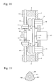
- Figs. 10 and 11 show the fifth embodiment of the present invention.
- reference numeral 71 denotes an output gear.
- the output gear 71 has an output shaft 72 and a pin 74 which are the same as those of the output gear 21 shown in Fig. 1 .
- the output gear 71 has a bevel gear of which the direction is opposite to that of the bevel gear shown in Fig. 1 , and the bevel gear of the output gear 71 is disposed at the inside of the second input gear 14.
- reference numeral 81 denotes a cam.
- three projections 82 having a cylindrical curved surface are formed at the peripheral portion of the cam 81 so as to be spaced 120 degrees from each other in a circumferential direction.
- the pin 74 of the output gear 71 is disposed between the projections 82, the pin 74 is pressed onto the peripheral surface of the cam 81 by the biasing force of the coil spring 23. In this condition, the output gear 71 is away from the second input gear 14.
- the cam 81 is rotated, and the pin 74 moves on the projection 82, so that the output gear 71 is moved toward the second input gear 14 against the biasing force of the coil spring 23, and the output gear 71 engages with the bevel gear portion 14b of the second input gear 14.
- the rotation of the motor 10 is transmitted to the output shaft 72.
- the dial 30 (not shown in the Figure) which is the same as in the first embodiment is fixed at the rotational shaft 31, and the switch 50 or the like (not shown in the Figure) are provided at the dial 30.
- the same actions and the effects as in the above embodiment can be obtained.
- the output gear 71 since the output gear 71 is moved toward the second input gear 14 by the projection 82 of the cam 81, even when permanent set occurs in the coil spring 23, the output gear 71 can reliably engage with the bevel gear portion 14b of the second input gear 14.
- the present invention is not limited to each of the above embodiments.
- a structure for example, the second input gear 14 and the output gear 21
- a structure in which frictional surfaces contact each other, or the like can be used.
- the operational member of the present invention is not limited to dials 30 and 35, and a feature (lever or the like) in which one end portion is rotated may be used.
- the structure for coupling with the movable sections of the seat shown in Fig. 4 is one example, and the positions and angles of the output gears 21 which are activated by the rotation of the dial 30 can be freely selected.
- the number of the output shafts can also be freely selected.
- a structure for performing the height adjustment of the seating face at two positions (front position and rear position) of the seat can be used, and a structure having four output shafts can also be used for this case.
- the first input gear 12 may be structured as a bevel gear, and the output gear 21 may engage with the first input gear 12.
- the selector member (the cam 41) of the present invention is rotated by the operational member (the dial 30), and the present invention includes an embodiment in which the selector member is linearly moved by the operational member.
- a sixth embodiment will be explained as this embodiment hereinafter.
- Figs. 12 and 13 show a multi-shaft drive device of the sixth embodiment.
- reference numeral 110 denotes a cam member (selector member).
- the cam member 110 is a horizontal plate-shaped member which is rectangular and long in the Y direction, and the cam member 110 is supported by a guide support member (not shown in the Figures) so as to be slidable in the longitudinal direction (Y direction, direction perpendicular to plane of the paper of Fig. 13 ).
- Both side surfaces extending in the longitudinal direction of the cam member 110 are cam surfaces 111, and plural recesses 112 opening in the thickness direction are formed at predetermined portions of these cam surfaces 111.
- Projections 113 extending in the Y direction are formed at both sides of the recesses 112 of the cam surfaces 111.
- a change portion extending from the recess 112 to the projection 113 are formed at an oblique plane.
- a rectangle hole 114 extending in the Y direction is formed at the center portion of the cam member 110.
- a rack portion 115 having teeth aligned in the Y direction is formed on one inside surface of the hole 114 which extends in the Y direction.
- a pinion gear 122 formed on an operational shaft 121 engages with the rack portion 115 (rack and pinion mechanism).
- the operational shaft 121 extends toward the upper side, and a circular plate-shaped dial (operational member) 120 is coaxially fixed at a leading end of the operational shaft 121.
- the dial 120 is rotated, so that the pinion gear 122 rotates together with the dial 120, and the rack portion 115 is driven by the pinion gear 122 and thereby moves in the Y direction.
- the cam member 110 moves linearly in the Y direction. That is, the operational shaft 121 is rotated in the R1 direction, so that the cam member 110 moves in the Y1 direction. The operational shaft 121 is rotated in the R2 direction, so that the cam member 110 moves in the Y2 direction.
- Plural output shafts (output members) 130 extending in the X direction are aligned in the Y direction at both sides of the X direction of the cam member 110.
- the output shafts 130 are supported by a support member (not shown in the Figures) so as to be movable toward and counter to the cam surface 111 in the axial direction (X direction).
- the output shaft 130 is structured such that a bevel gear 132 is integrally and coaxially formed at a middle portion of a shaft portion 131.
- the tooth surface of the bevel gear 132 faces the cam surface 111.
- a leading end (projection) of the shaft portion 131 which faces the cam surface 111 is formed in a curved shape.
- the cam member 110 is moved by the dial 120 in the Y direction, so that the output shafts 130 face the recess 112 or the projection 113.
- the output shaft 130 is biased by a compression spring 133 so as to move toward the cam surface 111.
- the compression spring 133 is provided along the peripheral surface of the shaft portion 131 and engages with the bevel gear 132.
- the cam member 110 moves in the Y direction and the recess 112 faces the output shaft 130, so that the leading end portion of the output shaft 130 is biased by the compression spring 133 so as to enter the recess 112.
- the projection 113 faces the output shaft 130, so that the output shaft 130 moves on the projection 113 against the force of the compression spring 133, and the output shaft 130 moves backward.
- a motor 140 which has a motor shaft (rotational shaft of motor) 141 extending in the upper direction, is disposed at the lower side of the cam member 110.
- a clutch shaft 143 extending in the upper and lower direction is connected to the motor shaft 141 via a power transmission member 142.
- the power transmission member 142 may be one which transmits the rotation of the motor shaft 141 to the clutch shaft 143 and may not be limited.
- a gear train, a belt, or the like may be used as a power transmission member 142.
- the clutch shaft 143 is provided to each output shaft 130, and a bevel gear 144 is integrally formed at the upper end of the clutch shaft 143.
- the power of the motor 140 is transmitted to each clutch shaft 143 via the power transmission member 142, and in the action of the motor 140, each clutch shaft 143 is rotated.
- the clutch shaft 143 forms an input member of the present invention, and a clutch mechanism 150 of this embodiment is formed by the clutch shaft 143 having the bevel gear 144 and the bevel gear 132 of the output shaft 130.
- the action of the motor 140 is set in a power-on condition or in a power-off condition by using a switch 123 provided on the dial 120.
- the output shaft 130 enters the recess 112 of the cam member 110, so that the bevel gear 132 engages with the bevel gear 144 proximate to the clutch shaft 143, and the bevel gear 132 is connected to the bevel gear 144.
- This connected condition is the left side condition in Fig. 13 .
- the power of the motor 140 is transmitted to the output shaft 130 via the power transmission member 142, the clutch shaft 143, and the clutch mechanism 150, and the output shaft 130 rotates.
- the dial 120 is operated so as to be rotated and the cam member 110 is moved in the Y direction, so that the output shaft 130 enters the recess 112 of the cam surface 111 of the cam member 110, the clutch mechanism 150 is in the connected condition, and this output shaft 130 rotates. Therefore, the output shaft 130 is selectively driven in accordance with the moved direction and the moved length in the Y direction of the cam member 110 by the rotation operation of the dial 120.
- the driven output shaft 130 is freely selected in accordance with the formed position of the recess 112 and the position of the output shaft 130.
- the formed position of the recess 112 and the position of the output shaft 130 are freely set, so that the number of the driven output shaft 130 can be set to one or be multiple.
- the output shaft 130 In the movement of the cam member 110, the output shaft 130 is biased by the compression spring 133, so that the leading end of the output shaft 130 always abuts on the cam surface 111, and the leading end thereof is alternately slid on the recess 112 and the projection 113.
- the leading end of the output shaft 130 is formed in a curved shape, and the change portion extending from the recess 112 to the projection 113 are formed at an oblique plane, the output shaft 130 smoothly slides on the cam surface 111.
- the position of the rack portion 115 can be freely selected.
- the rack portion 115 is formed on the inside surface of the hole 114 formed at the center of the cam member 110, and this is one example of a formed position of the rack portion 115.
- a projection 116 is integrally formed at one end portion of the longitudinal direction of the rack portion 115, and a hole 114 is formed at the projection 116.
- the same rack portion 115 is formed on the inside surface of the hole 114, and a pinion gear 122 of operational shaft 121 of dial 120 engages with the rack portion 115.
- the position of the dial 120 can be relatively apart from the output shaft 130.
- the output shaft 130 can also be disposed at a freely position to the cam surface 111 of the cam member 110.
- the freedom of the positions of the dial 120 including the operational shaft 121 and the output shaft 130 can be greatly improved. It is unnecessary to directly form the rack portion 115 at the cam member 110, and for example, the rack portion 115 may be indirectly formed at the cam member 110 via a transmission member (rod or the like). When the rack portion 115 is indirectly formed at the cam member 110, tooth row of the rack portion 115 may not be parallel to the movement direction of the cam member 110, and the tooth row of the rack portion 115 may be set freely, if possible.
- the cam member 110 can be thicker.
- stereoscopic alignment pattern can also be used such that the stacking of plural cam members 110 or the like is performed, the plural steps of the cam surfaces 111 are provided in the upper and lower direction, and the output shafts 130 are provided so as to correspond to cam surfaces 111.
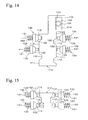
- Figs. 15 and 16 show specific examples of the above plural step structure, and show modification examples of the embodiment shown in Fig. 14 .
- two-stepped cam surfaces 111 are formed on both side surfaces of the cam member 110 in the thickness direction. That is, the cam surfaces 111 are formed in the two-stepped manner in a direction perpendicular to the above Y direction in which the cam surfaces 111 extend.
- the above recesses 112 are formed at predetermined positions of the upper cam surface 111 and the lower cam surface 111, and the output shafts 130, which correspond to the clutch mechanism 150, are aligned so as to correspond to the recesses 112. In this embodiment, it is advantageous that many output shafts 130 be provided to the device without the entirety of the device being long.
- the axial direction of the output shaft 130 is disposed parallel to the X direction in Fig. 12 .
- the axial direction of the output shaft 130 may be disposed such that the facing angle of the output shaft 130 to the cam surface 111 is oblique. This feature is advantageous in that the positioned angle of the output shaft 130 can be adjusted in accordance with the desirable direction when the extending direction of the desirable output shaft 130 is not parallel to the X direction.
- a stopper means which restricts the movement range of the cam member 110 is desirably provided since removal of the output shaft 130 from the cam surface 111 can be prevented.
- the stopper means may use any feature. For example, a member abutting at the end portion of the movement direction of the cam member 110 is used or a member controlling the rotation of the dial 120 is used.
- the clutch mechanism 150 is in the connected condition when the output shaft 130 enters the recess 112, and the clutch mechanism 150 is in the disconnected condition when the output shaft 130 moves on the projection 113.
- an opposite action feature can be used. That is, the clutch mechanism 150 is in the disconnected condition when the output shaft 130 enters the recess 112, and the clutch mechanism 150 is in the connected condition when the output shaft 130 moves on the projection 113.
- the multi-shaft drive device of the above embodiment is a desirable device used when a vehicle electrical seat is activated by the motor 140. That is, for example, each output shaft 130 is connected to movable mechanisms (for example, a mechanism which adjusts seating face height, a mechanism which adjusts an angle of seat backrest section, and a mechanism which adjusts a front-back position of seat) via a torque cable or the like, and the power of the motor 10 is selectively provided and transmitted to each movable mechanism so as to activate the movable mechanisms.
- the multi-shaft drive device of the present invention can be used not only for electrical seats but also for mechanical devices having plural movable mechanisms which are selectively driven.
- a motor 200 is activated, a motor shaft (rotational shaft) 201 is thereby rotated, an input gear (input member) 202 is a spur gear fixed at the motor shaft 201, rotation of the input gear 202 is transmitted to plural output shafts (output members) 210 via a clutch mechanism 220 provided to each output shaft 210, and the output shaft 210 to be rotated is selected by cam members (selector members) 230, 240, 250, 260, 270, and 280.
- This structure is a basic common structure in these embodiments.
- the output shaft 210 has the same structure as the output shaft 130 of the sixth embodiment.
- the output shaft 210 is constructed such that shaft portion 211 has a leading end formed in a curved shape and a bevel gear 212 is integrally and coaxially formed at a middle portion of the shaft portion 211.
- the tooth surface of the bevel gear 212 is directed to the leading end side.
- the leading end of the output shaft 210 is directed to the cam members 230, 240, 250, 260, 270, and 280, and the output shaft 210 is biased by a compression spring 213 engaging with the bevel gear portion 212 so as to move to the cam members 230, 240, 250, 260, 270, and 280 and abut thereto.
- the clutch mechanism 220 has a bevel gear 221 and the bevel gear 212 of the output shaft 210.
- the bevel gear 221 is disposed around the input gear 202 and rotates together with a spur gear 203 provided so as to engage with the input gear 202 and rotate.
- the bevel gear 212 can engage with the bevel gear 221.
- the cam members 230, 240, 250, 260, 270, and 280 mainly have corresponding characteristics, and the cam members 230, 240, 250, 260, 270, and 280 will be explained in each embodiment.
- the cam member 230 of the seventh embodiment is formed in a rectangular parallelepiped, and the cam member 230 is supported by a guide member (not shown in the Figures) so as to be maintained in a condition in which the longitudinal direction is horizontal in Fig. 17 and so as to be movable in the upper and lower direction.
- a dial shaft 231 which has a screw formed on a peripheral surface thereof, penetrates from the upper side to an end portion of the cam member 230 and is screwed thereto.
- a circular plate-shaped dial (not shown in the Figures) is concentrically fixed at an upper end of the dial shaft 231. The dial is rotated, and the cam member 230 thereby moves upward or downward in accordance with the rotation direction of the dial. That is, the dial shaft 231 and the cam member 230 consists of a ball screw mechanism.
- Recesses 233 are formed at both side surfaces 232a and 232b of the cam member 230 via oblique planes. The number and the formed position of the recess 233 are freely selected. In this case, the recesses 233 are formed at two positions (upper end portion and lower end portion) apart from each other in the longitudinal direction on the side surface 203a. The recess 233 is formed at a middle position of the upper and the lower direction on the side surface 203b, and this middle position corresponds to a position between the two recesses 233 formed on the side surface 232a.
- the output shafts 210 are disposed at both sides of the cam member 230.
- the output shafts 210 are supported so as to be movable toward and counter to the cam member 230 at positions such that the leading ends of the output shafts 210 are perpendicular to each side surface 232a and 232b and abut thereto and the leading ends thereof can be fitted into each recess 233.
- the output shafts 210 move backward against the force of the compression spring 213.
- the bevel gear 212 moves apart from the bevel gear 221, and the clutch mechanism 220 is in disconnected condition.
- the clutch mechanism 220 is disconnected, the power of the motor 200 is only transmitted to the bevel gear 221.
- a cam member 240 of the eighth embodiment is formed in a cylindrical shape, and the cam member 240 is supported by a bearing member (not shown in the Figures) so as to be rotatable around an axis of which direction is horizontal in Figs. 20 and 21 .
- a dial shaft 241 extending upward is connected to one end portion of the cam member 240 via bevel gears 242a and 242b engaging with each other.
- a circular plate-shaped dial (not shown in the Figures) is concentrically fixed at an upper end of the dial shaft 241. This dial is rotated, so that the cam member 240 rotates in a normal direction or an opposite direction in accordance with the rotational direction of the dial via the bevel gears 242a and 242b.
- Plural recesses 243 are variably formed in the axial direction on a peripheral surface 240a of the cam member 240.
- the number and the formed positions of the recesses 243 on the peripheral direction are freely selected.
- the recesses 243 are formed so as to be equally spaced from each other in the circumferential direction.
- the recess 243 is formed via the oblique plane such that the leading end of the output shaft 210 is smoothly separated from the recess 243. This structure is the same as those of the following embodiments.
- the output shafts 210 are arranged along the radial direction of the cam member 240 at both sides of the cam member 240.
- the output shafts 210 are supported so as to be movable toward and counter to the cam member 240 at positions such that the leading ends of the output shafts 210 are perpendicular to the peripheral surface 240a and abut thereto and the leading ends thereof can be fitted into each recess 243.
- the output shafts 210 move backward against the force of the compression spring 213. In this case, the clutch mechanism 220 is in disconnected condition.
- the dial is appropriately rotated and the cam member 240 thereby rotates, so that the leading end of the shaft portion 211 of the output shaft 210 is fitted into the recess 243, and the output shaft 210 moves forward to the cam member 240.
- the clutch mechanism 220 is in connected condition, and the power of the motor 200 is transmitted to the output shaft 210 of which the leading end of the shaft portion 211 fitted into the recess 243, and the output shaft 210 rotates.
- the spur gear 203 directly engages with the motor shaft 201.
- the spur gear 203 consists of the input member.
- the following embodiments 10 to 12 have this structure in the same manner.
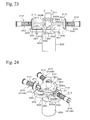
- a cam member 250 of the ninth embodiment is constructed such that two circular plates 252 having the same outer diameter are integrally and concentrically stacked.
- a dial (not shown in the Figures) is concentrically fixed at a dial shaft 251 provided at a center of the upper side circular plates 252.
- recesses 253 are formed at freely selected positions on a peripheral surface 252a of each circular plate 252. The number and the formed positions of the recesses 253 on the peripheral direction are freely selected. In this case, one recess 253 is formed at the upper side circular plate 252, and two recesses 253 are formed at the lower side circular plate 252.
- the output shaft 210 is disposed so as to face each circular plate 252 of the cam member 250.
- one output shaft 210 (hereinafter referred to as "201A”) is provided to the upper side circular plate 252, and two output shafts 210 (hereinafter referred to as “201B") are provided to the lower side circular plate 252.
- the output shafts 210 are supported so as to be movable toward and counter to the cam member 250 at positions such that the leading ends of the shaft portions 211 abut to the peripheral surface 252a of each circular plate 252.
- the output shaft 210 moves backward against the force of the compression spring 213.
- the clutch mechanism 220 is in a disconnected condition.
- the dial is appropriately rotated and the cam member 250 is thereby rotated, so that the leading end of the shaft portion 211 of the output shaft 210 is fitted into the recess 253 of each circular plate 252, and the output shaft 210 moves forward to the cam member 250.
- the clutch mechanism 220 is in connected condition, and the power of the motor 200 is transmitted to the output shaft 210 of which the leading end of the shaft portion 211 is fitted into the recess 253, and the output shaft 210 rotates.
- a cam member 260 is formed in a fan shape.
- the cam member 260 is integrally fixed at a dial shaft 261 of dial (not shown in the Figures) via a fan-shaped connecting plate 262.
- the cam member 260 uses the dial shaft 261 as a support point and is rotated by rotation of the dial.
- the cam member 260 has a peripheral surface 260a and an inner peripheral surface 260b, and recesses 263 are formed at the peripheral surface 260a and the inner peripheral surface 260b.
- the number and the formed position of the recesses 263 on the peripheral direction are freely selected. In this case, one recess 263 is formed approximately at the middle position of peripheral direction on the peripheral surface 260a, and one recess 263 is formed approximately at the middle position of peripheral direction on the inner peripheral surface 260b.
- the output shafts 210 are disposed so as to face the peripheral surface 260a and the inner peripheral surface 260b of the cam member 260.
- two output shafts 210 are provided at the peripheral surface 260a and one output shaft 210 is provided at the inner peripheral surface 260b.
- the output shafts 210 are supported so as to be movable toward and counter to the cam member 260 at positions such that the leading ends of the shaft portions 211 abut at the peripheral surface 260a and the inner peripheral surface 260b.
- the output shafts 210 move backward against the force of the compression spring 213. In this case, the clutch mechanism 220 is in disconnected condition.
- the dial is appropriately rotated and the cam member 260 is thereby rotated, so that the leading end of the shaft portion 211 is fitted into the recess 263, and the output shaft 210 moves forward to the cam member 263.
- the clutch mechanism 220 is in connected condition, and the power of the motor 200 is transmitted to the output shaft 210 of which the leading end of the shaft portion 211 is fitted into the recess 263 as described above, and the output shaft 210 rotates.
- the dial cannot be disposed between the output shafts 210, switching of action of the output shaft 210 is performed, and it is advantageous that the layout freedom is improved.
- a cam member 270 has a circular shape, and plural recesses 273 are formed at freely selected positions on a peripheral surface 270a thereof.
- the position of dial shaft 271 at which a dial (not shown in the Figures) is fixed is different from the rotational center of the cam member 270.
- the cam member 270 and the dial shaft 271 are connected by a pair of spur gears 272a and 272b. The dial is rotated, so that the cam member 270 rotates via the spur gears 272a and 272b.
- the output shafts 210 are disposed so as to face the peripheral surface 270a of the cam member 270 in the same manner as in the ninth embodiment.
- the output shaft 210 moves backward against the force of the compression spring 213. In this case, the clutch mechanism 220 is in disconnected condition.
- the dial is appropriately rotated and the cam member 270 is thereby rotated, so that the leading end of the shaft portion 211 of the output shaft 210 is fitted into the recess 273 of the cam member 270, and the output shaft 210 moves forward to the cam member 270.
- the clutch mechanism 220 is in connected condition, and the power of the motor 200 is transmitted to the output shaft 210 of which the leading end of the shaft portion 211 fitted into the recess 273, and the output shaft 210 rotates.
- a cam member 280 has a circular plate shape having plural recesses 283 formed at a peripheral surface 280a, and a dial (not shown in the Figures) is concentrically fixed via a dial shaft 281 provided at a center thereof.
- a dial (not shown in the Figures) is concentrically fixed via a dial shaft 281 provided at a center thereof.
- the leading ends of the shaft portion 211 do not abut directly on the peripheral surface 280a of the cam member 280, and leading ends of links 285, which are rotated by the output shafts 210 pressed by the compression springs 213, abut on the peripheral surface 280a and are fitted into the recesses 283.
- the clutch mechanism 220 is in disconnected condition.
- the above dial is appropriately rotated and the cam member 270 is thereby rotated, so that the leading end of the link 285 is fitted into the recess 283, and the output shaft 210 moves forward to the cam member 280.
- the clutch mechanism 220 is in connected condition, and the power of the motor 200 is transmitted to the output shaft 210 of which the leading end of the shaft portion 211 fitted into the recess 273, and the output shaft 210 rotates.
- the force, which is generated when the cam member 280 moves the link 285 outward from the recess 283, is increased by the principle of leverage, so that even when the force by the compression spring 213 is strong, the action of the device can be reliably executed.
- the position and the shape of the link 285 are improved, so that even when the cam member 280 is small and the depth of the recess 283 is not set large, the output shaft 210 can be greatly moved by the lever ratio of the link 285.
- many recesses 283 can be provided at the cam member 280, many output shaft 210 can be disposed, the output shafts 210 can be freely arranged, and the freedom of layout can be improved.
Landscapes
- Engineering & Computer Science (AREA)
- Mechanical Engineering (AREA)
- General Engineering & Computer Science (AREA)
- Aviation & Aerospace Engineering (AREA)
- Transportation (AREA)
- Gear Transmission (AREA)
- Seats For Vehicles (AREA)
- Transmission Devices (AREA)
Abstract
Description
- The present invention relates to a multi-shaft drive device in which plural output shafts are driven by one motor which is desirably used for, for example, electrical seats for vehicles or the like.
- In seats for vehicles, there are many features having parts of which plural positions can be adjusted (for example, front-back direction slide of entire seat, up-and-down motion of seating face height, or reclining of seatback (backrest) can be adjusted) in accordance with body type or position of a passenger. The adjustments of these movable parts have been manually performed, but electrical seats, which are adjusted by motor drive, are provided as more useful seats.
- In order to drive plural movable parts independently, an electrical seat is thought of as having a structure in which one motor is connected to each output shaft connected to the movable parts. However, the number of motors is increased. Therefore, it is efficient to drive plural output shafts by one motor. In order to realize this, it is known that motor power is transmitted to each output shaft, which is connected to plural movable parts, via a clutch, and the clutch is connected or disconnected and each movable part is selectively driven (see
Patent Documents 1 to 4). -
Patent Document 1 is Japanese Unexamined Patent Application Publication No.S58-97528 Patent Document 2 is Japanese Unexamined Patent Application Publication No.H6-87363 Patent Document 3 is Japanese Unexamined Patent Application Publication No.S62-183504 Patent Document 4 is Japanese Unexamined Patent Application Publication No.H6-156123 - In drive devices using an electromagnetic clutch disclosed in
Patent Documents Patent Documents Patent Documents - An object of the present invention is to provide a multi-shaft drive device which can perform weight reduction and space reduction by using a mechanical clutch having a simplified structure for driving plural output shafts by one motor.
- According to one aspect of the present invention, a multi-shaft drive device includes: an input member which is connected to a rotational shaft of a motor; plural output members which have an output shaft and are engageably provided to the input member, and to which rotation of the input member is transmitted when engaging with the input member; a selector member which is provided between the plural output members and has an action portion, the selector member being activated, the action portion facing one of the output members and acting thereon, thereby moving the one of the output members toward the input member and selectively engaging the one of the output members with the input member; and a rotary operational member which is connected to the selector member, the operational member being rotated so that selector member is activated.
- In the multi-shaft drive device as structured above, the selector member is rotated by the operational member, the action portion faces one of the output members, and the output member is moved toward the input member, and the output member engages with the input member. Thus, the rotation of the input member can be transmitted to the output member. In the one aspect of the present invention, since the mechanism for selectively providing the power of the motor to the plural output members and the selection of the output member to be activated are realized by a compact structure in which the output members are disposed around the selector member, weight reduction and space reduction can be performed.
- According to one desirable embodiment of the present invention, the action portion of the selector member may be a recess or a projection which is formed on a facing surface of the selector member which faces the output member.
- According to another desirable embodiment of the present invention, the action portion of the selector member may be provided in a condition of plural steps in a direction perpendicular to an activating direction of the selector member. In this embodiment, many output shafts can be arranged in accordance with the number of steps of the cam surface, and more output shafts can be provided in the device.
- According to another desirable embodiment of the present invention, facing angle of the output shaft with respect to the action portion may be freely selected. In this embodiment, the output member can be disposed in accordance with the extending direction of the desirable output member.
- According to another desirable embodiment of the present invention, the action portion may be the recess, and the output member may have a projection which projects from a front end surface of the output member and enters the recess. Alternatively, the action portion may be the projection, and the output member may be pressed by the projection.
- According to another desirable embodiment of the present invention, the output member may have a bevel gear, and the input member may have a bevel gear of which an axis crosses an axis of the bevel gear of the output member and engages with the bevel gear of the output member.
- According to another desirable embodiment of the present invention, the input member may be a spur gear to which rotation of the motor is transmitted, and the output member may have a spur gear which engages with the spur gear of the input member.
- According to another desirable embodiment of the present invention, action mode of the selector member may be rotation or linear movement.
- When the action mode of the selector member is rotation, the following embodiments can be desirably used.
- According to another desirable embodiment of the present invention, the multi-shaft drive device may have a biasing means which biases the output member toward the input member; and the selector member may have a peripheral portion and the recess, wherein the peripheral portion may have a cylindrical curved surface and may allow the output member to be apart from the input member by contacting the output member, and the recess may be provided at the peripheral portion and may allow the output member to enter the recess and to be moved toward the input member. In this embodiment, the recess may face the output member by rotation of the selector member, so that the output member may be moved by the biasing force of the biasing means, and may engage with the input member. Thus, by one action in which the selector member is rotated, the output member may engage with the input member. When the output member enters the recess, click feeling can be obtained. Therefore, the operability and the feeling of operation may be good.
- In the action portion of the present invention, a projection can be provided instead of the recess. That is, the multi-shaft drive device may have a biasing means which biases the output member in a direction in which the output member is apart from the input member, and the selector member may have a peripheral portion and the projection, the peripheral portion may have a cylindrical curved surface and may allow the output member to be apart from the input member by contacting the output member, the projection may be provided at the peripheral portion, and may press the output member and may thereby move the output member toward the input member. In this embodiment, by one action in which the selector member is rotated, the output member can be engaged with the input member.
- When the action mode of the selector member is rotation, the input member can consist of one gear. According to another desirable embodiment of the present invention, the input member may have: a first input gear which is connected to the rotational shaft of the motor; and plural second input gears which are provided at a peripheral side of the first input gear, wherein the second input gear may have: a first gear portion which engages with a peripheral portion of the first input gear; and a second gear portion which removably engages with the output member. In this embodiment, since the output member can be engaged with the second gear portion from an arbitrary direction, freedom of design can be increased as described hereinafter.
- That is, it is desirable that the output member can be freely positioned along a circle of which center is an axis of the second input gear. It is desirable that the second input gear can be freely positioned along a circle of which center is an axis of the first input gear. In the embodiment, the position and the angle of the output member can be appropriately changed in accordance with the position of the member to which the output member is connected or the like.
- When the action mode of the selector member is linear movement, the following embodiments can be used.
- According to another desirable embodiment of the present invention, the linear movement of the selector member may be performed by a rack and pinion mechanism provided between the selector member and the operational member.
- According to another desirable embodiment of the present invention, the multi-shaft drive device may have a biasing means which biases the output member toward the input member and the selector member may have a cam surface and the recess, the cam surface may allow the output member to be apart from the input member by contacting the output member, and the recess may be provided at the cam surface and may allow the output member to enter the recess and to be moved toward the input member. In this embodiment, when the output member enters the recess, click feeling can be obtained, so that the operability and the feeling of operation may be good.
- According to another desirable embodiment of the present invention, the multi-shaft drive device may have a biasing means which biases the output member in a direction in which the output member is apart from the input member, and the selector member may have a cam surface and the recess, the cam surface may allow the output member to be apart from the input member by contacting the output member, the projection may be provided at the cam surface, and may press the output member and may thereby move the output member toward the input member.
- According to another desirable embodiment of the present invention, the multi-shaft drive device may have a stopper means which controls a movement range of the selector member. In this embodiment, removal of the output member from the cam surface can be prevented.
- According to another desirable embodiment of the present invention, multi-shaft drive device may use a feature in which a movable portion of a predetermined movable mechanism is connected to the output member, a switch which activates the motor is slidably provided at the operational member, the switch is slid in one direction, and the motor is thereby rotated in a normal direction, and the switch is slid in a direction opposite to the one direction, and the motor is thereby rotated in a reverse direction, and slide direction of the switch corresponds to a movable direction of the movable portion. The movable mechanism can be a vehicle seat. In this case, the output member may be connected to an adjustment mechanism of the movable portion of the vehicle seat. In this embodiment, the feeling of operation corresponds to the actual movement, and there is an advantage that the multi-shaft drive device is thereby easily used.
- According to the present invention, since the mechanism for selectively providing the power of the motor to the plural output members and the selection of the output member to be activated are obtained by a compact structure, weight reduction and space reduction can be performed.
-
-
Fig. 1 is a front view of a multi-shaft drive device, which includes local sectional view of a portion thereof and is taken along line I-I inFig. 3 of a first embodiment according to the present invention. -
Fig. 2 is a perspective view taken along line II -II inFig. 1 . -
Fig. 3 is an arrow view taken in the direction of arrow III inFig. 1 . -
Fig. 4 is a side view showing a use example of the multi-shaft drive of the first embodiment. -
Fig. 5 is a front view of a multi-shaft drive device of a second embodiment according to the present invention, which includes local sectional view of a portion thereof. -
Fig. 6 is an arrow view taken in the direction of arrow VI inFig. 5 . -
Fig. 7 is a front view of a multi-shaft drive device of a third embodiment according to the present invention, which includes local sectional view of a portion thereof. -
Fig. 8 is an arrow view taken in the direction of arrow VIII- VIII inFig. 7 . -
Fig. 9 is a front view of a multi-shaft drive device of a fourth embodiment according to the present invention, which includes local sectional view of a portion thereof. -
Fig. 10 is a local sectional front view of a multi-shaft drive device of a fifth embodiment according to the present invention, which includes local sectional view of a portion thereof. -
Fig. 11 is an axial direction cross sectional view of a cam of the fifth embodiment. -
Fig. 12 is a plan view schematically showing a multi-shaft drive device of a sixth embodiment according to the present invention. -
Fig. 13 is a front view schematically showing the multi-shaft drive device of the sixth embodiment. -
Fig. 14 is a plan view showing a modification example of the sixth embodiment. -
Fig. 15 is a side view showing another modification example of the sixth embodiment. -
Fig. 16 is a plan view showing the above another modification example of the sixth embodiment. -
Fig. 17 is a perspective view showing a main section of a multi-shaft drive device of a seventh embodiment according to the present invention. -
Fig. 18 is a plan view of the seventh embodiment. -
Fig. 19 is a side view of the seventh embodiment. -
Fig. 20 is a perspective view showing a main section of a multi-shaft drive device of an eighth embodiment according to the present invention. -
Fig. 21 is a perspective view of the eighth embodiment viewed from another direction. -
Fig. 22 is a plan view of the eighth embodiment. -
Fig. 23 is a side view of the eighth embodiment. -
Fig. 24 is a perspective view showing a main section of a multi-shaft drive device of a ninth embodiment according to the present invention. -
Fig. 25 is a plan view of the ninth embodiment. -
Fig. 26 is a plan view of the ninth embodiment in which a cam member is transparently drawn. -
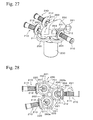
Fig. 27 is a perspective view showing a main section of a multi-shaft drive device of a tenth embodiment according to the present invention. -
Fig. 28 is a plan view of the tenth embodiment in which a cam member is transparently drawn. -
Fig. 29 is a perspective view showing a main section of a multi-shaft drive device of an eleventh embodiment according to the present invention. -
Fig. 30 is a plan view of the eleventh embodiment. -
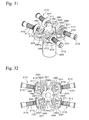
Fig. 31 is a perspective view showing a main section of a multi-shaft drive device of a twelfth embodiment according to the present invention. -
Fig. 32 is a plan view of the twelfth embodiment. - Reference numerals 10, 140, and 200 denote a motor, 11,141, and 201 denote a motor shaft (rotational shaft of motor), 12 denotes a first input gear (spur gear), 14 denotes a second input gear (input member), 14a denotes a spur gear portion (first gear portion), 14b denotes a bevel gear portion (second gear portion), 21 denotes an output gear (output member), 22, 25, 62, and 72 denote an output shaft (output member), 23 and 133 denote a coil spring (biasing means), 24 denotes a pin (projection), 30 and 120 denote a dial (operational member), 41 denotes a cam (selector member), 42, 112, 233, 243, 253, 263, 273, and 283 denote a recess (action portion), 50 denotes a switch, 61 denotes an output gear (output member), 110, 230, 240, 250, 260, 270, and 280 denote a cam member (selector member), 111 denotes a cam surface (action portion), 130 denotes an output shaft (output member), 133 and 213 denote a compression spring (biasing member), 143 denotes a clutch shaft (input member), 202 denotes an input gear (input member), and 210 denotes an output shaft (output member).
- Embodiments of the present invention will be described with reference to the Figures hereinafter.
-
Figs. 1 to 4C show a multi-shaft drive device of the first embodiment. For example, this multi-shaft drive device is desirably constructed such that three movable mechanisms of vehicle electrical seat (electrical seat used for vehicles) are activated by onemotor 10 which rotates in a normal direction and an opposite direction. In this case, the three movable mechanisms are a mechanism which adjusts seating face height, a mechanism which adjusts an angle of seat backrest section, and a mechanism which adjusts a front-back position of seat. The power of themotor 10 is selectively provided so as to activate the movable mechanisms. - As shown in
Fig. 1 , themotor 10 is fixed to amain frame 1 having a circular plate-shape. In this case, one end portion of themotor 10, at which a motor shaft (rotational shaft of motor) 11 projects, is fixed to themain frame 1. Afirst input gear 12 is fixed at a leading end of themotor shaft 11. Threebearings 13 are disposed around themotor 10 in a concentric pattern of which center is positioned at themotor 10.Shafts 15 of second input gears (input members) 14 are rotatably supported by thebearings 13. The second input gears 14 have spur gear portions (first gear portions) 14a and bevel gear portions (second gear portions) 14b. Thespur gear portion 14a engages with thefirst input gear 12. Thebevel gear portion 14b is positioned apart a predetermined distance from thespur gear portion 14a. The three second input gears 14 are positioned such that each rotational center of the three second input gears 14 is positioned at a vertex of an isosceles triangle. - A rectangular plate-shaped
subframe 2 is provided on themain frame 1. An end portion of thesubframe 2 is cut to have a semicircular shape, and the end portion is fitted into a side surface of thebearing 13. Thesubframe 2 is rotated around thebearing 13, so that thesubframe 2 can be positioned and fixed at a desired position. Bearing blocks 3 are provided on a surface of thesubframe 2, andoutput shafts 22 of output gears (output members) 21 are rotatably supported by the bearing blocks 3. Theoutput gear 21 is a bevel gear which can engage with thebevel gear portion 14b of thesecond input gear 14, and theoutput gear 21 is biased toward the leading end side thereof (the side of thebevel gear portion 14b) by acoil spring 23. Apin 24 projecting toward the leading end side is integrally formed at a center of front end surface of theoutput gear 21. The leading end of thepin 24 is formed to have a hemispherical shape. - In
Figs. 1 and3 ,reference numeral 30 denotes a circular plate-shaped dial (operational member). Thedial 30 has arotational shaft 31 at a center thereof. Therotational shaft 31 extends coaxially with themotor shaft 11 and is rotatably supported by aframe 4. A cam (selector member) 41 is fixed at an end portion of therotational shaft 31. - The
cam 41 has a circular plate-shape, and recesses 42 having a roughly trapezoidal shape are formed at a peripheral portion thereof. As shown inFig. 2 , thepin 24 of one of the output gears 21 is projected toward the leading side thereof by thecoil spring 23, thereby entering therecess 42, and theoutput gear 21 engages with thebevel gear portion 14b of thesecond input gear 14. Thus, the rotation of themotor 10 is transmitted from thefirst input gear 12 and thesecond input gear 14 to theoutput shaft 22 through theoutput gear 21. - On the other hand, the
pins 24 of the other two output gears 21 abut to a peripheral surface of thecam 41, and theoutput gear 21 is apart from thebevel gear portion 14b of thesecond input gear 14. As shown inFigs. 1 to 3 , thepin 24 of theoutput gear 21, which is positioned to have an apex angle of isosceles triangle, enters therecess 42. In this condition, when each contact point, at which thepins 24 of the other two output gears 21 contact the peripheral surface of thecam 41, and the center point of thefirst input gear 12 are connected with a straight line, centers of the other tworecesses 42 are positioned at points inclined at predetermined angle θ (45 degrees in this embodiment) from each straight line. - Therefore, when the
cam 41 is rotated by 45 degrees from the condition shown inFig. 2 in clockwise direction, thepin 24 of theoutput gear 21 enters therecess 42 at the upper side of thecam 41, and thepins 24 of the other two output gears 21 move on the peripheral surface of thecam 41. In contrast, when thecam 41 is rotated by 45 degrees from the condition shown inFig. 2 in counterclockwise direction, thepin 24 of theoutput gear 21 enters therecess 42 at the lower side of thecam 41, and thepins 24 of the other two output gears 21 move on the peripheral surface of thecam 41. Thus, thecam 41 is rotated by 45 degrees, so that one of the output gears 21 can engage with thebevel gear portion 14b of thesecond input gear 14. - The rotation of the
cam 41 is performed by rotation of thedial 30. Thepin 24 enters therecess 42, so that click feeling in operation can be obtained, and thedial 30 can be reliably positioned at a connection position of theoutput gear 21. - A
switch 50 having a rectangular parallelepiped shape is provided at a surface of thedial 30, and theswitch 50 is used for selection of ON/OFF and rotational direction of themotor 10. Theswitch 50 slides toward both sides of longitudinal direction (C-D direction inFig. 3 ), and theswitch 50 is controlled so as to stop at a middle point of slide range by a biasing member (not shown in the Figures). Theswitch 50 extends so as to pass through the center point of thedial 30, and one end portion of theswitch 50 projects from thedial 30 and is positioned at the outside thereof. The projection end of theswitch 50 is used as anindication portion 51. - As shown in
Fig. 3 , in the condition in which thepin 24 of theoutput gear 21 positioned to have an apex angle of an isosceles triangle enters therecess 42, theswitch 50 is provided to thedial 30 such that theindication portion 51 is inclined at 45 degrees from a center line of thepin 24 in a counterclockwise direction. - When the
switch 50 is positioned at the middle point in the stop condition in which theswitch 50 does not move in a longitudinal direction, themotor 10 is in a power-off condition. For example, when theswitch 50 slides in the C direction, themotor 10 rotates in a normal direction. For example, when theswitch 50 slides in the D direction, themotor 10 rotates in an opposite direction. In this manner, themotor 10 is driven. - The multi-shaft drive device of the first embodiment has the above structure. Next, an example in which the multi-shaft drive device is used for vehicle electric seat will be explained with reference to
Figs. 4A to 4C . - First, the multi-shaft drive device is provided at a position on a side surface of seat cushion, and th position allows a passenger, who sits on the seat cushion, to operate the
dial 30. In this case, themotor shaft 11 extends in right and left direction of vehicle body, and thesecond input gear 14 positioned to have an apex angle of the isosceles triangle is positioned in the travel direction of the vehicle, and the other second input gears 14 are arranged at upper side and lower side of rear side of the vehicle. Thesecond input gear 14 positioned at the front side is a front sidesecond input gear 14A, thesecond input gear 14 positioned at the lower side is a lower sidesecond input gear 14B, and thesecond input gear 14 positioned at the upper side is an upper sidesecond input gear 14C. Regarding the output gears 21, theoutput gear 21 positioned at the front side is a frontside output gear 21A, theoutput gear 21 positioned at the lower side is a lowerside output gear 21B, and theoutput gear 21 positioned at the upper side is an upperside output gear 21C. - A torque cable (not shown in the Figures) is connected to the
output shaft 22 of eachoutput gear 21A to 21C. The torque cables transmit rotation of eachoutput shaft 22 to the reclining mechanism which adjusts an angle of seat backrest section, the front-back position adjustment mechanism of the seat, and the seating face height adjustment mechanism, and the torque cables activate the mechanisms. In this case, theoutput shaft 22 of the frontside output gear 21A is connected to the reclining mechanism via the torque cable. Theoutput shaft 22 of the lowerside output gear 21B is connected to the seating face height adjustment mechanism via the torque cable. Theoutput shaft 22 of the upperside output gear 21C is connected to the front-back position adjustment mechanism of the seat via the torque cable. A method for activating each mechanism by using the multi-shaft drive device will be explained hereinafter. - In order to adjust the front-back position of the seat by activating the front-back position adjustment, the
dial 30 is rotated, and as shown inFig. 4A , theindication portion 51 of theswitch 50 is directed to the front side. Then, therecess 42 of thecam 41 moves so as to face the upper sidesecond input gear 14C, thepin 24 of the upperside output gear 21C enters therecess 42, and the upperside output gear 21C engages with the upper sidesecond input gear 14C. On the other hand, in the frontside output gear 21A and the lowerside output gear 21B, thepins 24 contact the peripheral surface of thecam 41, and thepins 24 are apart from the front sidesecond input gear 14A and the lower sidesecond input gear 14B. - From this condition, when the
switch 50 slides in the front direction (C direction), themotor 10 is rotated, so that the entirety of the seat moves to the front side. When theswitch 50 slides in the back direction (D direction), themotor 10 is rotated, so that the entirety of the seat moves to the rear side. Theswitch 50 is appropriately moved in the front-back direction, so that the front-back position of the seat can be adjusted at a desired position. - In order to adjust the angle of the seat backrest section by the reclining mechanism, the
dial 30 is rotated, and as shown inFig. 4B , theindication portion 51 of theswitch 50 is directed to the front side and obliquely downward at 45 degrees. Then, therecess 42 of thecam 41 moves so as to face the front sidesecond input gear 14A, thepin 24 of the frontside output gear 21A enters therecess 42, and the frontside output gear 21A engages with the front sidesecond input gear 14A. On the other hand, in the lowerside output gear 21B and the upperside output gear 21C, thepins 24 contact the peripheral surface of thecam 41, and thepins 24 are apart from the lower sidesecond input gear 14B and the upper sidesecond input gear 14C. - From this condition, when the
switch 50 slides in the diagonally forward direction (C direction), themotor 10 is rotated, so that the backrest of the seat is inclined to the front side. When theswitch 50 slides in the diagonally backward direction (D direction), themotor 10 is rotated, so that the backrest of the seat is inclined to the back side. Theswitch 50 is appropriately moved in the upper and lower direction, so that the backrest can be adjusted at a desired position. - In order to adjust the height of the seating face by activating the seating face height adjustment mechanism, the
dial 30 is rotated, and as shown inFig. 4C , theindication portion 51 of theswitch 50 is directed to the lower side. Then, therecess 42 of thecam 41 moves so as to face the lower sidesecond input gear 14B, thepin 24 of the lowerside output gear 21B enters therecess 42, and the lowerside output gear 21B engages with the lower sidesecond input gear 14B. On the other hand, in the frontside output gear 21A and the upperside output gear 21C, thepins 24 contact the peripheral surface of thecam 41, and thepins 24 are apart from the front sidesecond input gear 14A and the upper sidesecond input gear 14C. - From this condition, when the
switch 50 slides to the lower direction (C direction), themotor 10 is rotated, so that the seating face moves downwardly. When theswitch 50 slides to the upper direction (D direction), themotor 10 is rotated, so that the seating face moves upwardly. Theswitch 50 is appropriately moved in the upper and lower direction, so that the seating face can be adjusted at a desired position. - According to the multi-shaft drive device of the above first embodiment, the mechanism for selectively providing the power of the
motor 10 to theplural output shafts 22 is constructed such that theoutput gear 21 which is integrally formed to eachoutput shaft 22 engages with thesecond input gear 14. Thedial 30 is rotated, and theoutput gear 21 to be connected is moved to thesecond input gear 14, so that selection of theoutput shaft 22 is performed. - That is, since the mechanism for selectively providing the power of the
motor 10 to the plural output gears 21 and the selection of theoutput gear 21 to be activated are obtained by a compact structure, weight reduction and space reduction can be obtained. - In particular, in the above embodiment, by one action in which the
cam 41 is rotated, theoutput gear 21 engages with thesecond input gear 14, and when thepin 24 of theoutput gear 21 enters therecess 42, click feeling can be obtained. Thus, the operability and the feeling of operation are good. - The position of the
output gear 21 can be freely set along the surrounding area of thesecond input gear 14, and thesecond input gear 14 and theoutput gear 21 can be freely set along the surrounding area of thefirst input gear 12. Thus, the position and the angle of theoutput shaft 22 can be appropriately changed in accordance with the position of the member, which is connected to theoutput shaft 22, or the like. - As shown in
Figs. 4A to 4C , the position and the operational direction of theswitch 50 in the condition in which the multi-shaft drive device is provided to the seat correspond to the movable direction of the movable mechanisms (the reclining mechanism, the front-back position adjustment mechanism of the seat, and the seating face height adjustment mechanism of seat) to be adjusted. Thus, the feeling of operation corresponds to the actual movement, and the multi-shaft drive device is thereby easily used. -
Figs. 5 and 6 show the second embodiment of the present invention. The second embodiment is structured such that the rotational shaft of themotor 10 is disposed perpendicularly to the rotational shaft of thefirst input gear 12 in the structure of the first embodiment. - As shown in
Fig. 6 , athird input gear 11a which consists of a bevel gear is fixed at the leading end of themotor shaft 11 of themotor 10. Aninput shaft 16 is fixed at a center of thefirst input gear 12. Afourth input gear 16a which consists of a bevel gear engaging with thethird input gear 11a is fixed at the leading end of theinput gear 16. - In the second embodiment, the
motor 10 is rotated, the rotation of themotor shaft 11 is transmitted from thethird input gear 11a to thefourth input gear 16a, thefirst input gear 12 is rotated, and thesecond input gear 14 engaging with thefirst input gear 12 is rotated. Thedial 30 is rotated, thepin 24 of theoutput gear 21 enters the recess of thecam 41, and theoutput gear 21 engages with thesecond input gear 14, so that theoutput shaft 22 fixed at theoutput gear 21 is rotated. -
Figs. 7 and8 show the third embodiment of the present invention. The third embodiment is constructed such that in the structure of the first embodiment, the rotational operation of the dial 30 (hereinafter referred to as "first dial 30" in this embodiment) is performed by using another dial (second dial) 35 and switching of connection of theoutput gear 21 is thereby performed. - The
first dial 30 is rotatably supported by one surface side (right side inFig. 7 ) of aframe 70 via arotational shaft 30a. As shown inFig. 8 , thesecond dial 35 is rotatably supported by the other surface side (left side inFig. 7 ) of theframe 70 via arotational shaft 35a. In this case, thesecond dial 35 is positioned around thefirst dial 30 so as not to be coaxial with thefirst dial 30. Aswitch 50A having the same structure as that of theswitch 50 is provided on thesecond dial 35. When the multi-shaft drive device is used for movable type vehicle seat in the same manner as in the first embodiment, theframe 70 is a frame (seat frame or the like). - As shown in
Fig. 8 , therotational shaft 35a of thesecond dial 35 penetrates theframe 70 and projects on the one surface side, and a transmission belt (transmission member) 80 is wound on therotational shaft 35a of thesecond dial 35 and therotational shaft 30a of thefirst dial 30. Thesecond dial 35 is rotated, and the rotation thereof is transmitted to thefirst dial 30 via thetransmission belt 80, so that thefirst dial 30 is rotated and switching of connection of theoutput gear 21 is thereby performed. - In the third embodiment, the
second dial 35 is disposed at a freely selected position apart from thefirst dial 30, and eachdial transmission belt 80. Thus, the selection of the output shaft 25 which is driven by thecam 41 can be performed at a position flexible to the provided positions of thecam 41 and thedial 30. Thus, design freedom can be improved.
Instead of thetransmission belt 80, one gear or gear train, with which plural gears engage, is used as means for transmitting the rotation of thesecond dial 35 to thefirst dial 30. -
Fig. 9 shows the fourth embodiment of the present invention. As shown inFig. 9 , three bearingblocks 60 are supported by amain frame 5 supporting themotor 10 so as to be slidable toward and counter to thefirst input gear 12. Aspring washer 5a is provided at a peripheral portion of themain frame 5, and thecoil spring 23 is disposed between thespring washer 5a and thebearing block 60. The bearingblock 60 is biased toward the rotational center of thefirst input gear 12 by thecoil spring 23. - An
output shaft 62 of an output gear (output member) 61 is rotatably supported by the bearingblock 60. Theoutput gear 61 is a spur gear which can engage with thefirst input gear 12. Apin 64 projecting to one end side is integrally formed at the center of one end surface of theoutput gear 61. - In the fourth embodiment, the cam 40, the
dial 30, and theswitch 50, and the like are provided in the same manner as in the first embodiment. Threerecesses 42 are formed at about the same positions of thecam 41 as in the first embodiment. On the other hand, the bearing blocks 60 are disposed to form an isosceles triangle. As shown inFigs. 4A to 4C , every time thedial 30 is rotated by 45 degrees, thepin 64 of theoutput gear 61 enters therecess 42, and theoutput gear 61 engages with thefirst input gear 12. That is, thedial 30 is rotated from the condition shown inFig. 9 , so that thepin 64 which entered therecess 42 moves on the peripheral surface of thecam 41, and theoutput gear 61 is apart from thefirst input gear 12. When thepin 64 of theoutput gear 61 proximate to theabove output gear 61 faces therecess 42, the bearingblock 60 moves toward thefirst input gear 12 by the biasing force of thecoil spring 23, and theoutput gear 61 engages with thefirst input gear 12. Thus, the rotation of themotor 10 is transmitted to theoutput shaft 62. - In the above fourth embodiment, the same actions and the effects as in the above embodiment can be obtained. In particular, in the above fourth embodiment, since the
output gear 61 directly engages with thefirst input gear 12, the number of the gears is greatly reduced, and the structure is simplified. -
Figs. 10 and 11 show the fifth embodiment of the present invention. InFig. 10 ,reference numeral 71 denotes an output gear. Theoutput gear 71 has anoutput shaft 72 and apin 74 which are the same as those of theoutput gear 21 shown inFig. 1 . Theoutput gear 71 has a bevel gear of which the direction is opposite to that of the bevel gear shown inFig. 1 , and the bevel gear of theoutput gear 71 is disposed at the inside of thesecond input gear 14. - In
Fig. 10 ,reference numeral 81 denotes a cam. As shown inFig. 11 , threeprojections 82 having a cylindrical curved surface are formed at the peripheral portion of thecam 81 so as to be spaced 120 degrees from each other in a circumferential direction. When thepin 74 of theoutput gear 71 is disposed between theprojections 82, thepin 74 is pressed onto the peripheral surface of thecam 81 by the biasing force of thecoil spring 23. In this condition, theoutput gear 71 is away from thesecond input gear 14. From this condition, thecam 81 is rotated, and thepin 74 moves on theprojection 82, so that theoutput gear 71 is moved toward thesecond input gear 14 against the biasing force of thecoil spring 23, and theoutput gear 71 engages with thebevel gear portion 14b of thesecond input gear 14. Thus, the rotation of themotor 10 is transmitted to theoutput shaft 72. In the fifth embodiment, too, the dial 30 (not shown in the Figure) which is the same as in the first embodiment is fixed at therotational shaft 31, and theswitch 50 or the like (not shown in the Figure) are provided at thedial 30. - In the above fifth embodiment, the same actions and the effects as in the above embodiment can be obtained. In particular, in the above fifth embodiment, since the
output gear 71 is moved toward thesecond input gear 14 by theprojection 82 of thecam 81, even when permanent set occurs in thecoil spring 23, theoutput gear 71 can reliably engage with thebevel gear portion 14b of thesecond input gear 14. - The present invention is not limited to each of the above embodiments. For example, instead of the structure (for example, the
second input gear 14 and the output gear 21) in which teeth engage with each other, a structure, in which frictional surfaces contact each other, or the like can be used. The operational member of the present invention is not limited todials - The structure for coupling with the movable sections of the seat shown in
Fig. 4 is one example, and the positions and angles of the output gears 21 which are activated by the rotation of thedial 30 can be freely selected. The number of the output shafts can also be freely selected. For example, a structure for performing the height adjustment of the seating face at two positions (front position and rear position) of the seat can be used, and a structure having four output shafts can also be used for this case. - In the first embodiment, instead of the structure in which the
output gear 21 engages with thesecond input gear 14, thefirst input gear 12 may be structured as a bevel gear, and theoutput gear 21 may engage with thefirst input gear 12. - In the above first to fifth embodiments, the selector member (the cam 41) of the present invention is rotated by the operational member (the dial 30), and the present invention includes an embodiment in which the selector member is linearly moved by the operational member. A sixth embodiment will be explained as this embodiment hereinafter.
-
Figs. 12 and 13 show a multi-shaft drive device of the sixth embodiment. In these Figures,reference numeral 110 denotes a cam member (selector member). Thecam member 110 is a horizontal plate-shaped member which is rectangular and long in the Y direction, and thecam member 110 is supported by a guide support member (not shown in the Figures) so as to be slidable in the longitudinal direction (Y direction, direction perpendicular to plane of the paper ofFig. 13 ). Both side surfaces extending in the longitudinal direction of thecam member 110 arecam surfaces 111, andplural recesses 112 opening in the thickness direction are formed at predetermined portions of these cam surfaces 111.Projections 113 extending in the Y direction are formed at both sides of therecesses 112 of the cam surfaces 111. A change portion extending from therecess 112 to theprojection 113 are formed at an oblique plane. - A
rectangle hole 114 extending in the Y direction is formed at the center portion of thecam member 110. Arack portion 115 having teeth aligned in the Y direction is formed on one inside surface of thehole 114 which extends in the Y direction. Apinion gear 122 formed on anoperational shaft 121 engages with the rack portion 115 (rack and pinion mechanism). As shown inFig. 13 , theoperational shaft 121 extends toward the upper side, and a circular plate-shaped dial (operational member) 120 is coaxially fixed at a leading end of theoperational shaft 121. Thedial 120 is rotated, so that thepinion gear 122 rotates together with thedial 120, and therack portion 115 is driven by thepinion gear 122 and thereby moves in the Y direction. Thus, thecam member 110 moves linearly in the Y direction. That is, theoperational shaft 121 is rotated in the R1 direction, so that thecam member 110 moves in the Y1 direction. Theoperational shaft 121 is rotated in the R2 direction, so that thecam member 110 moves in the Y2 direction. - Plural output shafts (output members) 130 extending in the X direction are aligned in the Y direction at both sides of the X direction of the
cam member 110. In this case, the leading end of eachoutput shaft 130 faces thecam surface 111. Theoutput shafts 130 are supported by a support member (not shown in the Figures) so as to be movable toward and counter to thecam surface 111 in the axial direction (X direction). Theoutput shaft 130 is structured such that abevel gear 132 is integrally and coaxially formed at a middle portion of ashaft portion 131. In this case, the tooth surface of thebevel gear 132 faces thecam surface 111. A leading end (projection) of theshaft portion 131 which faces thecam surface 111 is formed in a curved shape. Thecam member 110 is moved by thedial 120 in the Y direction, so that theoutput shafts 130 face therecess 112 or theprojection 113. - The
output shaft 130 is biased by acompression spring 133 so as to move toward thecam surface 111. Thecompression spring 133 is provided along the peripheral surface of theshaft portion 131 and engages with thebevel gear 132. Thecam member 110 moves in the Y direction and therecess 112 faces theoutput shaft 130, so that the leading end portion of theoutput shaft 130 is biased by thecompression spring 133 so as to enter therecess 112. Theprojection 113 faces theoutput shaft 130, so that theoutput shaft 130 moves on theprojection 113 against the force of thecompression spring 133, and theoutput shaft 130 moves backward. - As shown in
Fig. 13 , amotor 140, which has a motor shaft (rotational shaft of motor) 141 extending in the upper direction, is disposed at the lower side of thecam member 110. Aclutch shaft 143 extending in the upper and lower direction is connected to themotor shaft 141 via apower transmission member 142. Thepower transmission member 142 may be one which transmits the rotation of themotor shaft 141 to theclutch shaft 143 and may not be limited. For example, a gear train, a belt, or the like may be used as apower transmission member 142. - The
clutch shaft 143 is provided to eachoutput shaft 130, and abevel gear 144 is integrally formed at the upper end of theclutch shaft 143. The power of themotor 140 is transmitted to eachclutch shaft 143 via thepower transmission member 142, and in the action of themotor 140, eachclutch shaft 143 is rotated. Theclutch shaft 143 forms an input member of the present invention, and aclutch mechanism 150 of this embodiment is formed by theclutch shaft 143 having thebevel gear 144 and thebevel gear 132 of theoutput shaft 130. The action of themotor 140 is set in a power-on condition or in a power-off condition by using aswitch 123 provided on thedial 120. - In this
clutch mechanism 150, theoutput shaft 130 enters therecess 112 of thecam member 110, so that thebevel gear 132 engages with thebevel gear 144 proximate to theclutch shaft 143, and thebevel gear 132 is connected to thebevel gear 144. This connected condition is the left side condition inFig. 13 . The power of themotor 140 is transmitted to theoutput shaft 130 via thepower transmission member 142, theclutch shaft 143, and theclutch mechanism 150, and theoutput shaft 130 rotates. In the condition in which theoutput shaft 130 moves on theprojection 113 of thecam member 110, thebevel gear 132 proximate to theoutput shaft 130 is separated from thebevel gear 144 proximate to theclutch shaft 143, theclutch shaft 143 is idling, and theoutput shaft 130 does not rotate. This disconnected condition is the right side condition inFig. 13 . - In the above multi-shaft drive device, the
dial 120 is operated so as to be rotated and thecam member 110 is moved in the Y direction, so that theoutput shaft 130 enters therecess 112 of thecam surface 111 of thecam member 110, theclutch mechanism 150 is in the connected condition, and thisoutput shaft 130 rotates. Therefore, theoutput shaft 130 is selectively driven in accordance with the moved direction and the moved length in the Y direction of thecam member 110 by the rotation operation of thedial 120. The drivenoutput shaft 130 is freely selected in accordance with the formed position of therecess 112 and the position of theoutput shaft 130. The formed position of therecess 112 and the position of theoutput shaft 130 are freely set, so that the number of the drivenoutput shaft 130 can be set to one or be multiple. - In the movement of the
cam member 110, theoutput shaft 130 is biased by thecompression spring 133, so that the leading end of theoutput shaft 130 always abuts on thecam surface 111, and the leading end thereof is alternately slid on therecess 112 and theprojection 113. In this case, since the leading end of theoutput shaft 130 is formed in a curved shape, and the change portion extending from therecess 112 to theprojection 113 are formed at an oblique plane, theoutput shaft 130 smoothly slides on thecam surface 111. - In the multi-shaft drive device of the embodiment, in a case in which the
cam member 110 can be moved in the Y direction, the position of therack portion 115 can be freely selected. InFig. 12 , therack portion 115 is formed on the inside surface of thehole 114 formed at the center of thecam member 110, and this is one example of a formed position of therack portion 115. For example, as shown inFig. 14 , aprojection 116 is integrally formed at one end portion of the longitudinal direction of therack portion 115, and ahole 114 is formed at theprojection 116. Thesame rack portion 115 is formed on the inside surface of thehole 114, and apinion gear 122 ofoperational shaft 121 ofdial 120 engages with therack portion 115. In this feature, the position of thedial 120 can be relatively apart from theoutput shaft 130. - Thus, there is no restriction in the position of the
dial 120 having theoperational shaft 121 for operating the connection and disconnection of theclutch mechanism 150. Theoutput shaft 130 can also be disposed at a freely position to thecam surface 111 of thecam member 110. For the above reasons, the freedom of the positions of thedial 120 including theoperational shaft 121 and theoutput shaft 130 can be greatly improved. It is unnecessary to directly form therack portion 115 at thecam member 110, and for example, therack portion 115 may be indirectly formed at thecam member 110 via a transmission member (rod or the like). When therack portion 115 is indirectly formed at thecam member 110, tooth row of therack portion 115 may not be parallel to the movement direction of thecam member 110, and the tooth row of therack portion 115 may be set freely, if possible. -
Many output shaft 130 can be aligned along thecam surface 111 unless they interfere with each other, and if necessary, thecam surface 111 is long, so thatmore output shafts 130 can be aligned. - The
cam member 110 can be thicker. Alternatively, stereoscopic alignment pattern can also be used such that the stacking ofplural cam members 110 or the like is performed, the plural steps of the cam surfaces 111 are provided in the upper and lower direction, and theoutput shafts 130 are provided so as to correspond to cam surfaces 111.Figs. 15 and16 show specific examples of the above plural step structure, and show modification examples of the embodiment shown inFig. 14 . In this case, two-steppedcam surfaces 111 are formed on both side surfaces of thecam member 110 in the thickness direction. That is, the cam surfaces 111 are formed in the two-stepped manner in a direction perpendicular to the above Y direction in which the cam surfaces 111 extend. The above recesses 112 are formed at predetermined positions of theupper cam surface 111 and thelower cam surface 111, and theoutput shafts 130, which correspond to theclutch mechanism 150, are aligned so as to correspond to therecesses 112. In this embodiment, it is advantageous thatmany output shafts 130 be provided to the device without the entirety of the device being long. - In the above embodiment, the axial direction of the
output shaft 130 is disposed parallel to the X direction inFig. 12 . Instead of this, as shown in the dotted line inFig. 12 , the axial direction of theoutput shaft 130 may be disposed such that the facing angle of theoutput shaft 130 to thecam surface 111 is oblique. This feature is advantageous in that the positioned angle of theoutput shaft 130 can be adjusted in accordance with the desirable direction when the extending direction of thedesirable output shaft 130 is not parallel to the X direction. - In the above embodiment, a stopper means which restricts the movement range of the
cam member 110 is desirably provided since removal of theoutput shaft 130 from thecam surface 111 can be prevented. The stopper means may use any feature. For example, a member abutting at the end portion of the movement direction of thecam member 110 is used or a member controlling the rotation of thedial 120 is used. - In the above embodiment, the
clutch mechanism 150 is in the connected condition when theoutput shaft 130 enters therecess 112, and theclutch mechanism 150 is in the disconnected condition when theoutput shaft 130 moves on theprojection 113. Instead of this feature, an opposite action feature can be used. That is, theclutch mechanism 150 is in the disconnected condition when theoutput shaft 130 enters therecess 112, and theclutch mechanism 150 is in the connected condition when theoutput shaft 130 moves on theprojection 113. - The multi-shaft drive device of the above embodiment is a desirable device used when a vehicle electrical seat is activated by the
motor 140. That is, for example, eachoutput shaft 130 is connected to movable mechanisms (for example, a mechanism which adjusts seating face height, a mechanism which adjusts an angle of seat backrest section, and a mechanism which adjusts a front-back position of seat) via a torque cable or the like, and the power of themotor 10 is selectively provided and transmitted to each movable mechanism so as to activate the movable mechanisms. However, the multi-shaft drive device of the present invention can be used not only for electrical seats but also for mechanical devices having plural movable mechanisms which are selectively driven. - The seventh to the twelfth embodiments of the present invention will be explained with reference to
Figs. 17 to 32 . In these embodiments, amotor 200 is activated, a motor shaft (rotational shaft) 201 is thereby rotated, an input gear (input member) 202 is a spur gear fixed at themotor shaft 201, rotation of theinput gear 202 is transmitted to plural output shafts (output members) 210 via aclutch mechanism 220 provided to eachoutput shaft 210, and theoutput shaft 210 to be rotated is selected by cam members (selector members) 230, 240, 250, 260, 270, and 280. This structure is a basic common structure in these embodiments. - The
output shaft 210 has the same structure as theoutput shaft 130 of the sixth embodiment. Theoutput shaft 210 is constructed such thatshaft portion 211 has a leading end formed in a curved shape and abevel gear 212 is integrally and coaxially formed at a middle portion of theshaft portion 211. In this case, the tooth surface of thebevel gear 212 is directed to the leading end side. The leading end of theoutput shaft 210 is directed to thecam members output shaft 210 is biased by acompression spring 213 engaging with thebevel gear portion 212 so as to move to thecam members clutch mechanism 220 has abevel gear 221 and thebevel gear 212 of theoutput shaft 210. Thebevel gear 221 is disposed around theinput gear 202 and rotates together with aspur gear 203 provided so as to engage with theinput gear 202 and rotate. Thebevel gear 212 can engage with thebevel gear 221. In the seventh to the twelfth embodiments, thecam members cam members - The
cam member 230 of the seventh embodiment is formed in a rectangular parallelepiped, and thecam member 230 is supported by a guide member (not shown in the Figures) so as to be maintained in a condition in which the longitudinal direction is horizontal inFig. 17 and so as to be movable in the upper and lower direction. Adial shaft 231, which has a screw formed on a peripheral surface thereof, penetrates from the upper side to an end portion of thecam member 230 and is screwed thereto. A circular plate-shaped dial (not shown in the Figures) is concentrically fixed at an upper end of thedial shaft 231. The dial is rotated, and thecam member 230 thereby moves upward or downward in accordance with the rotation direction of the dial. That is, thedial shaft 231 and thecam member 230 consists of a ball screw mechanism. -
Recesses 233 are formed at bothside surfaces cam member 230 via oblique planes. The number and the formed position of therecess 233 are freely selected. In this case, therecesses 233 are formed at two positions (upper end portion and lower end portion) apart from each other in the longitudinal direction on the side surface 203a. Therecess 233 is formed at a middle position of the upper and the lower direction on the side surface 203b, and this middle position corresponds to a position between the tworecesses 233 formed on theside surface 232a. - The
output shafts 210 are disposed at both sides of thecam member 230. Theoutput shafts 210 are supported so as to be movable toward and counter to thecam member 230 at positions such that the leading ends of theoutput shafts 210 are perpendicular to eachside surface recess 233. When the leading ends of theoutput shafts 210 abut on theside surfaces output shafts 210 move backward against the force of thecompression spring 213. In this case, thebevel gear 212 moves apart from thebevel gear 221, and theclutch mechanism 220 is in disconnected condition. When theclutch mechanism 220 is disconnected, the power of themotor 200 is only transmitted to thebevel gear 221. - When the dial is rotated, the rotation of
dial shaft 231 is transformed into upward or downward movement of thecam member 230, and the leading end of theshaft portion 211 is fitted into therecess 233 via the oblique plane, so that theoutput shaft 210 moves forward to thecam member 230. In this manner, thebevel gear 212 engages with theshaft portion 221, theclutch mechanism 220 is in connected condition. Thus, the power of themotor 200 is transmitted to theoutput shaft 210 of which the leading end of theshaft portion 211 fitted into therecess 233, and theoutput shaft 210 rotates. The dial is rotated, so that thecam member 230 moves upward and downward, and the leading end of theoutput shaft 210 moves away from therecess 233. Thus, theclutch mechanism 220 is in disconnected condition. - A
cam member 240 of the eighth embodiment is formed in a cylindrical shape, and thecam member 240 is supported by a bearing member (not shown in the Figures) so as to be rotatable around an axis of which direction is horizontal inFigs. 20 and21 . Adial shaft 241 extending upward is connected to one end portion of thecam member 240 viabevel gears dial shaft 241. This dial is rotated, so that thecam member 240 rotates in a normal direction or an opposite direction in accordance with the rotational direction of the dial via thebevel gears -
Plural recesses 243 are variably formed in the axial direction on aperipheral surface 240a of thecam member 240. The number and the formed positions of therecesses 243 on the peripheral direction are freely selected. In this case, as shown inFig. 23 , therecesses 243 are formed so as to be equally spaced from each other in the circumferential direction. Therecess 243 is formed via the oblique plane such that the leading end of theoutput shaft 210 is smoothly separated from therecess 243. This structure is the same as those of the following embodiments. - The
output shafts 210 are arranged along the radial direction of thecam member 240 at both sides of thecam member 240. Theoutput shafts 210 are supported so as to be movable toward and counter to thecam member 240 at positions such that the leading ends of theoutput shafts 210 are perpendicular to theperipheral surface 240a and abut thereto and the leading ends thereof can be fitted into eachrecess 243. When the leading ends of theoutput shafts 210 abut on theperipheral surface 240a of thecam member 240, theoutput shafts 210 move backward against the force of thecompression spring 213. In this case, theclutch mechanism 220 is in disconnected condition. - The dial is appropriately rotated and the
cam member 240 thereby rotates, so that the leading end of theshaft portion 211 of theoutput shaft 210 is fitted into therecess 243, and theoutput shaft 210 moves forward to thecam member 240. In this manner, theclutch mechanism 220 is in connected condition, and the power of themotor 200 is transmitted to theoutput shaft 210 of which the leading end of theshaft portion 211 fitted into therecess 243, and theoutput shaft 210 rotates. - In the ninth embodiment, the
spur gear 203 directly engages with themotor shaft 201. Thespur gear 203 consists of the input member. The followingembodiments 10 to 12 have this structure in the same manner. - A
cam member 250 of the ninth embodiment is constructed such that twocircular plates 252 having the same outer diameter are integrally and concentrically stacked. A dial (not shown in the Figures) is concentrically fixed at adial shaft 251 provided at a center of the upper sidecircular plates 252. In thiscam member 250, recesses 253 are formed at freely selected positions on aperipheral surface 252a of eachcircular plate 252. The number and the formed positions of therecesses 253 on the peripheral direction are freely selected. In this case, onerecess 253 is formed at the upper sidecircular plate 252, and tworecesses 253 are formed at the lower sidecircular plate 252. - The
output shaft 210 is disposed so as to face eachcircular plate 252 of thecam member 250. In this embodiment, one output shaft 210 (hereinafter referred to as "201A") is provided to the upper sidecircular plate 252, and two output shafts 210 (hereinafter referred to as "201B") are provided to the lower sidecircular plate 252. Theoutput shafts 210 are supported so as to be movable toward and counter to thecam member 250 at positions such that the leading ends of theshaft portions 211 abut to theperipheral surface 252a of eachcircular plate 252. When the leading end of theshaft portion 211 abuts on theperipheral surface 252a of eachcam member 250, theoutput shaft 210 moves backward against the force of thecompression spring 213. In this case, theclutch mechanism 220 is in a disconnected condition. - The dial is appropriately rotated and the
cam member 250 is thereby rotated, so that the leading end of theshaft portion 211 of theoutput shaft 210 is fitted into therecess 253 of eachcircular plate 252, and theoutput shaft 210 moves forward to thecam member 250. In this manner, theclutch mechanism 220 is in connected condition, and the power of themotor 200 is transmitted to theoutput shaft 210 of which the leading end of theshaft portion 211 is fitted into therecess 253, and theoutput shaft 210 rotates. When the surfaces are provided in condition of plural steps as described in this embodiment, it is advantageous thatmany output shafts 210 be arranged in accordance with the number of steps, andmore output shafts 210 can be provided in the device. - In the tenth embodiment, a
cam member 260 is formed in a fan shape. Thecam member 260 is integrally fixed at adial shaft 261 of dial (not shown in the Figures) via a fan-shaped connectingplate 262. Thecam member 260 uses thedial shaft 261 as a support point and is rotated by rotation of the dial. Thecam member 260 has aperipheral surface 260a and an innerperipheral surface 260b, and recesses 263 are formed at theperipheral surface 260a and the innerperipheral surface 260b. The number and the formed position of therecesses 263 on the peripheral direction are freely selected. In this case, onerecess 263 is formed approximately at the middle position of peripheral direction on theperipheral surface 260a, and onerecess 263 is formed approximately at the middle position of peripheral direction on the innerperipheral surface 260b. - The
output shafts 210 are disposed so as to face theperipheral surface 260a and the innerperipheral surface 260b of thecam member 260. In this embodiment, twooutput shafts 210 are provided at theperipheral surface 260a and oneoutput shaft 210 is provided at the innerperipheral surface 260b. Theoutput shafts 210 are supported so as to be movable toward and counter to thecam member 260 at positions such that the leading ends of theshaft portions 211 abut at theperipheral surface 260a and the innerperipheral surface 260b. When the leading ends of theshaft portions 211 abut at theperipheral surface 260a and the innerperipheral surface 260b, theoutput shafts 210 move backward against the force of thecompression spring 213. In this case, theclutch mechanism 220 is in disconnected condition. - The dial is appropriately rotated and the
cam member 260 is thereby rotated, so that the leading end of theshaft portion 211 is fitted into therecess 263, and theoutput shaft 210 moves forward to thecam member 263. Theclutch mechanism 220 is in connected condition, and the power of themotor 200 is transmitted to theoutput shaft 210 of which the leading end of theshaft portion 211 is fitted into therecess 263 as described above, and theoutput shaft 210 rotates. In this embodiment, even when the dial cannot be disposed between theoutput shafts 210, switching of action of theoutput shaft 210 is performed, and it is advantageous that the layout freedom is improved. - In the eleventh embodiment, a
cam member 270 has a circular shape, andplural recesses 273 are formed at freely selected positions on aperipheral surface 270a thereof. The position ofdial shaft 271 at which a dial (not shown in the Figures) is fixed is different from the rotational center of thecam member 270. Thecam member 270 and thedial shaft 271 are connected by a pair ofspur gears cam member 270 rotates via thespur gears - The
output shafts 210 are disposed so as to face theperipheral surface 270a of thecam member 270 in the same manner as in the ninth embodiment. When the leading end of theshaft portion 211 abuts on theperipheral surface 270a of thecam member 270, theoutput shaft 210 moves backward against the force of thecompression spring 213. In this case, theclutch mechanism 220 is in disconnected condition. - The dial is appropriately rotated and the
cam member 270 is thereby rotated, so that the leading end of theshaft portion 211 of theoutput shaft 210 is fitted into therecess 273 of thecam member 270, and theoutput shaft 210 moves forward to thecam member 270. In this manner, theclutch mechanism 220 is in connected condition, and the power of themotor 200 is transmitted to theoutput shaft 210 of which the leading end of theshaft portion 211 fitted into therecess 273, and theoutput shaft 210 rotates. - In this embodiment, in the same manner as in the tenth embodiment, even when the dial cannot be disposed between the
output shafts 210, switching of action of theoutput shaft 210 is performed, and it is advantageous in that the layout freedom is improved. The gear ratio of thespur gears - In the twelfth embodiment, a
cam member 280 has a circular plate shape havingplural recesses 283 formed at aperipheral surface 280a, and a dial (not shown in the Figures) is concentrically fixed via adial shaft 281 provided at a center thereof. In this embodiment, inplural output shafts 210 disposed around thecam member 280, the leading ends of theshaft portion 211 do not abut directly on theperipheral surface 280a of thecam member 280, and leading ends oflinks 285, which are rotated by theoutput shafts 210 pressed by the compression springs 213, abut on theperipheral surface 280a and are fitted into therecesses 283. - That is, when the leading end of the
link 285 abuts on theperipheral surface 280a of thecam member 280, theoutput shaft 210 moves backward against the force of thecompression spring 213. In this case, theclutch mechanism 220 is in disconnected condition. The above dial is appropriately rotated and thecam member 270 is thereby rotated, so that the leading end of thelink 285 is fitted into therecess 283, and theoutput shaft 210 moves forward to thecam member 280. Thus, in theoutput shaft 210, theclutch mechanism 220 is in connected condition, and the power of themotor 200 is transmitted to theoutput shaft 210 of which the leading end of theshaft portion 211 fitted into therecess 273, and theoutput shaft 210 rotates. - In the structure in which the
link 285 is disposed between thecam member 280 and theoutput shaft 210, the force, which is generated when thecam member 280 moves thelink 285 outward from therecess 283, is increased by the principle of leverage, so that even when the force by thecompression spring 213 is strong, the action of the device can be reliably executed. The position and the shape of thelink 285 are improved, so that even when thecam member 280 is small and the depth of therecess 283 is not set large, theoutput shaft 210 can be greatly moved by the lever ratio of thelink 285. Thus,many recesses 283 can be provided at thecam member 280,many output shaft 210 can be disposed, theoutput shafts 210 can be freely arranged, and the freedom of layout can be improved.
Claims (21)
- A multi-shaft drive device comprising:an input member which is connected to a rotational shaft of a motor;plural output members which have an output shaft and are engageably provided to the input member, and to which rotation of the input member is transmitted when engaging with the input member;a selector member which is provided between the plural output members and has an action portion, the selector member being activated, the action portion facing one of the output members and acting thereon, thereby moving the one of the output members toward the input member and selectively engaging the one of the output members with the input member; anda rotary operational member which is connected to the selector member, the operational member being rotated so that selector member is activated.
- A multi-shaft drive device according to claim 1, wherein
the action portion of the selector member is a recess or a projection which is formed on a facing surface of the selector member which faces the output member. - A multi-shaft drive device according to claim 1 or 2, wherein
the action portion of the selector member is provided in a condition of plural steps in a direction perpendicular to an activating direction of the selector member. - A multi-shaft drive device according to one of claims 1 to 3, wherein
facing angle of the output shaft with respect to the action portion is freely selected. - A multi-shaft drive device according to one of claims 2 to 4, wherein
the action portion is the recess, and the output member has a projection which projects from a front end surface of the output member and enters the recess. - A multi-shaft drive device according to one of claims 2 to 4, wherein
the action portion is the projection, and the output member is pressed by the projection. - A multi-shaft drive device according to one of claims 1 to 6, wherein
the output member has a bevel gear, and the input member has a bevel gear of which an axis crosses an axis of the bevel gear of the output member and engages with the bevel gear of the output member. - A multi-shaft drive device according to one of claims 1 to 6, wherein
the input member is a spur gear to which rotation of the motor is transmitted, and the output member has a spur gear which engages with the spur gear of the input member. - A multi-shaft drive device according to one of claims 1 to 8, wherein
action mode of the selector member is rotation. - A multi-shaft drive device according to claim 9, wherein
the multi-shaft drive device has a biasing means which biases the output member toward the input member; and
the selector member has a peripheral portion and the recess, wherein the peripheral portion has a cylindrical curved surface and allows the output member to be apart from the input member by contacting the output member, and
the recess is provided at the peripheral portion and allows the output member to enter the recess and to be moved toward the input member. - A multi-shaft drive device according to claim 9, wherein
the multi-shaft drive device has a biasing means which biases the output member in a direction in which the output member is apart from the input member, and
the selector member has a peripheral portion and the projection,
the peripheral portion has a cylindrical curved surface and allows the output member to be apart from the input member by contacting the output member,
the projection is provided at the peripheral portion, and presses the output member and thereby moves the output member toward the input member. - A multi-shaft drive device according to one of claims 9 to 11, wherein the input member has:a first input gear which is connected to the rotational shaft of the motor; andplural second input gears which are provided at a peripheral side of the first input gear, whereinthe second input gear has:a first gear portion which engages with a peripheral portion of the first input gear; anda second gear portion which removably engages with the output member.
- A multi-shaft drive device according to claim 12, wherein
the output member can be freely positioned along a circle of which center is an axis of the second input gear. - A multi-shaft drive device according to claim 12 or 13, wherein
the second input gear can be freely positioned along a circle of which center is an axis of the first input gear. - A multi-shaft drive device according to one of claims 1 to 8, wherein
action mode of the selector member is linear movement. - A multi-shaft drive device according to claim 15, wherein
the linear movement of the selector member is performed by a rack and pinion mechanism provided between the selector member and the operational member. - A multi-shaft drive device according to claim 15 or 16, wherein
the multi-shaft drive device has a biasing means which biases the output member toward the input member and
the selector member has a cam surface and the recess,
the cam surface allows the output member to be apart from the input member by contacting the output member, and
the recess is provided at the cam surface and allows the output member to enter the recess and to be moved toward the input member. - A multi-shaft drive device according to claim 15 or 16, wherein
the multi-shaft drive device has a biasing means which biases the output member in a direction in which the output member is apart from the input member, and
the selector member has a cam surface and the recess,
the cam surface allows the output member to be apart from the input member by contacting the output member,
the projection is provided at the cam surface, and presses the output member and thereby moves the output member toward the input member. - A multi-shaft drive device according to one of claims 15 to 18, wherein
the multi-shaft drive device has a stopper means which controls a movement range of the selector member. - A multi-shaft drive device according to one of claims 1 to 19, wherein
a movable portion of a predetermined movable mechanism is connected to the output member,
a switch which activates the motor is slidably provided at the operational member,
the switch is slid in one direction, and the motor is thereby rotated in a normal direction, and the switch is slid in a direction opposite to the one direction, and the motor is thereby rotated in a reverse direction, and
slide direction of the switch corresponds to a movable direction of the movable portion. - A multi-shaft drive device according to claim 20, wherein
the movable mechanism is a vehicle seat, and
the output member is connected to an adjustment mechanism of the movable portion of the vehicle seat.
Applications Claiming Priority (3)
| Application Number | Priority Date | Filing Date | Title |
|---|---|---|---|
| JP2009197958 | 2009-08-28 | ||
| JP2010112816 | 2010-05-17 | ||
| PCT/JP2010/064628 WO2011024964A1 (en) | 2009-08-28 | 2010-08-27 | Multi-shaft drive device |
Publications (2)
| Publication Number | Publication Date |
|---|---|
| EP2472143A1 true EP2472143A1 (en) | 2012-07-04 |
| EP2472143A4 EP2472143A4 (en) | 2014-09-17 |
Family
ID=43628062
Family Applications (1)
| Application Number | Title | Priority Date | Filing Date |
|---|---|---|---|
| EP10812013.0A Withdrawn EP2472143A4 (en) | 2009-08-28 | 2010-08-27 | TRAINING DEVICE WITH MULTIPLE TREES |
Country Status (6)
| Country | Link |
|---|---|
| US (1) | US9027442B2 (en) |
| EP (1) | EP2472143A4 (en) |
| JP (3) | JP4880088B2 (en) |
| KR (2) | KR20130141733A (en) |
| CN (1) | CN102472365B (en) |
| WO (1) | WO2011024964A1 (en) |
Cited By (1)
| Publication number | Priority date | Publication date | Assignee | Title |
|---|---|---|---|---|
| WO2018096426A1 (en) * | 2016-11-26 | 2018-05-31 | Kpit Technologies Limited | Bi-directional actuator |
Families Citing this family (12)
| Publication number | Priority date | Publication date | Assignee | Title |
|---|---|---|---|---|
| JP5692536B2 (en) * | 2011-10-24 | 2015-04-01 | アイシン精機株式会社 | Sheet drive device |
| US9068515B2 (en) | 2011-12-07 | 2015-06-30 | United Technologies Corporation | Accessory gearbox with tower shaft removal capability |
| WO2014193960A1 (en) | 2013-05-28 | 2014-12-04 | Caleb Chung | Multiple-output transmission |
| CN103791031A (en) * | 2014-01-14 | 2014-05-14 | 长春绿野农业装备科技有限公司 | Dual-purpose agricultural machine transmission case for paddy land and dry land |
| CN106828211B (en) * | 2017-02-21 | 2019-02-22 | 广州视源电子科技股份有限公司 | Seat angle adjusting device |
| CN109835318B (en) * | 2017-11-24 | 2023-08-22 | 常州中车铁马科技实业有限公司 | Hydraulic brake system for rail transit vehicle and control method thereof |
| CN108891310B (en) * | 2018-08-21 | 2023-10-20 | 安道拓(重庆)汽车部件有限公司 | Motor-shared automobile seat adjusting system |
| KR102825668B1 (en) * | 2019-02-19 | 2025-06-25 | 일리노이즈 툴 워크스 인코포레이티드 | Drive unit for operating multiple functions of an air vent system of an air distribution system and an air vent system having this type of drive unit |
| US11602337B2 (en) * | 2019-04-24 | 2023-03-14 | Nuvasive, Inc. | Transmission assembly |
| CN110843620B (en) * | 2019-11-29 | 2021-03-16 | 安徽江淮汽车集团股份有限公司 | Electric seat of automobile |
| CN111776641B (en) * | 2020-04-27 | 2022-04-26 | 北京京东乾石科技有限公司 | Meshing adapting mechanism and logistics system |
| CN113928756A (en) * | 2020-06-29 | 2022-01-14 | 广东威林科技股份有限公司 | Garbage can |
Family Cites Families (28)
| Publication number | Priority date | Publication date | Assignee | Title |
|---|---|---|---|---|
| US3119537A (en) * | 1962-06-27 | 1964-01-28 | Robert G Smits | Multiple differential rotary mechanical drive |
| JPS5028181U (en) * | 1973-07-10 | 1975-04-01 | ||
| JPS5028181A (en) * | 1973-07-16 | 1975-03-22 | ||
| JPS5441898Y2 (en) * | 1976-06-09 | 1979-12-06 | ||
| JPS5328449U (en) * | 1976-08-18 | 1978-03-10 | ||
| US4090413A (en) * | 1976-10-29 | 1978-05-23 | Ford Aerospace & Communications Corp. | Cyclic motion generator |
| JPS54108169A (en) * | 1978-02-15 | 1979-08-24 | Yamaha Motor Co Ltd | Change gear device |
| DE2846632A1 (en) * | 1978-10-26 | 1980-05-08 | Keiper Automobiltechnik Gmbh | HEIGHT ADJUSTMENT DEVICE FOR SEATS, IN PARTICULAR MOTOR VEHICLE SEATS |
| DE2901208C2 (en) * | 1979-01-13 | 1984-08-09 | Keiper Automobiltechnik Gmbh & Co Kg, 5630 Remscheid | Adjustable seat, especially vehicle seat |
| JPS56113258U (en) * | 1980-01-30 | 1981-09-01 | ||
| JPS5918971B2 (en) * | 1980-02-06 | 1984-05-01 | 株式会社 中村屋 | Manufacturing method for reduced sugar confectionery |
| JPS5897528A (en) | 1981-12-01 | 1983-06-10 | Shiraki Kinzoku Kogyo Kk | 6-way power shift regulator |
| US4895052A (en) * | 1983-10-21 | 1990-01-23 | Gleasman Vernon E | Steer-driven reduction drive system |
| JPS60164154U (en) * | 1984-04-10 | 1985-10-31 | スズキ株式会社 | outboard motor shift device |
| JPS62183504A (en) | 1986-02-07 | 1987-08-11 | Matsushita Electric Ind Co Ltd | High voltage transformer |
| US4819507A (en) * | 1987-01-14 | 1989-04-11 | Societe Redex | Device for simultaneously driving the screws of two parallel screw-and-nut systems |
| JPS6418201A (en) * | 1987-07-14 | 1989-01-23 | Teikoku Tsushin Kogyo Kk | Rotary knob structure of electronic component |
| SE464287B (en) * | 1987-10-12 | 1991-04-08 | Haakansson Bengt E W | DEVICE TO REGULATE OBJECTS OF THE DRIVING ENVIRONMENT IN A VEHICLE |
| CN2124686U (en) | 1992-06-11 | 1992-12-16 | 张鹏飞 | Magnetic health electric tooth-brush |
| JPH0687363A (en) | 1992-09-07 | 1994-03-29 | Mitsuba Electric Mfg Co Ltd | Drive device for vehicle 8-way power seat |
| JPH0643399U (en) * | 1992-11-20 | 1994-06-07 | 株式会社タチエス | Geared motor |
| JPH06156123A (en) | 1992-11-25 | 1994-06-03 | Mitsuba Electric Mfg Co Ltd | Device for driving movable part of power seat for vehicle |
| US5791622A (en) * | 1996-07-02 | 1998-08-11 | Lear Corporation | Vehicle power seat adjuster with flex cable guides |
| US6626064B1 (en) * | 2000-08-08 | 2003-09-30 | Lear Corporation | Single motor module for a vehicle seat |
| CA2421525A1 (en) * | 2000-09-07 | 2002-03-14 | Intier Automotive Inc. | Triple output transfer case for a vehicle seat |
| CN2504437Y (en) * | 2001-07-04 | 2002-08-07 | 吴声震 | Right-angle reductor |
| DE10247703B3 (en) | 2002-10-12 | 2004-04-08 | Faurecia Autositze Gmbh & Co. Kg | Motor vehicle seat adjuster has a fixed drive motor with cogs magnetically brought into contact with the cogs of several adjusting devices |
| CA2761044C (en) * | 2010-12-22 | 2017-10-31 | Magna Seating Inc. | Single motor power seat |
-
2010
- 2010-08-27 EP EP10812013.0A patent/EP2472143A4/en not_active Withdrawn
- 2010-08-27 CN CN201080038249.1A patent/CN102472365B/en not_active Expired - Fee Related
- 2010-08-27 KR KR1020137033292A patent/KR20130141733A/en not_active Withdrawn
- 2010-08-27 KR KR20127006396A patent/KR101362635B1/en not_active Expired - Fee Related
- 2010-08-27 JP JP2011506512A patent/JP4880088B2/en active Active
- 2010-08-27 WO PCT/JP2010/064628 patent/WO2011024964A1/en not_active Ceased
- 2010-08-27 US US13/391,777 patent/US9027442B2/en active Active
-
2011
- 2011-11-30 JP JP2011262324A patent/JP5318935B2/en active Active
- 2011-11-30 JP JP2011262336A patent/JP2012102879A/en active Pending
Cited By (1)
| Publication number | Priority date | Publication date | Assignee | Title |
|---|---|---|---|---|
| WO2018096426A1 (en) * | 2016-11-26 | 2018-05-31 | Kpit Technologies Limited | Bi-directional actuator |
Also Published As
| Publication number | Publication date |
|---|---|
| CN102472365A (en) | 2012-05-23 |
| JP2012102879A (en) | 2012-05-31 |
| JP4880088B2 (en) | 2012-02-22 |
| EP2472143A4 (en) | 2014-09-17 |
| CN102472365B (en) | 2015-02-25 |
| WO2011024964A1 (en) | 2011-03-03 |
| JPWO2011024964A1 (en) | 2013-01-31 |
| JP5318935B2 (en) | 2013-10-16 |
| US9027442B2 (en) | 2015-05-12 |
| JP2012107752A (en) | 2012-06-07 |
| US20120144943A1 (en) | 2012-06-14 |
| KR20120052391A (en) | 2012-05-23 |
| KR20130141733A (en) | 2013-12-26 |
| KR101362635B1 (en) | 2014-02-12 |
Similar Documents
| Publication | Publication Date | Title |
|---|---|---|
| US9027442B2 (en) | Multi-shaft drive device | |
| US9604550B2 (en) | Seat drive device | |
| KR101498401B1 (en) | Power transmission mechanism and multi-shaft drive device | |
| JP4985744B2 (en) | Sheet device | |
| US9446690B2 (en) | Power seat operation device and power seat | |
| US9121482B2 (en) | Multi-shaft drive device | |
| JP5797734B2 (en) | Multi-axis drive | |
| US9388891B2 (en) | Multi-shaft drive device | |
| JPWO2010084882A1 (en) | Multi-axis drive | |
| JP2012177459A (en) | Multi-shaft driving device | |
| JP2012176734A (en) | Multiaxial driving device | |
| JP2012177460A (en) | Bevel gear, power transmission mechanism, and multishaft driving device | |
| JP2012180852A (en) | Multi-axis driving device | |
| JP2018134985A (en) | Seat drive device | |
| JP2011011731A (en) | Power seat adjuster | |
| JP2011011732A (en) | Power seat adjuster |
Legal Events
| Date | Code | Title | Description |
|---|---|---|---|
| PUAI | Public reference made under article 153(3) epc to a published international application that has entered the european phase |
Free format text: ORIGINAL CODE: 0009012 |
|
| 17P | Request for examination filed |
Effective date: 20120328 |
|
| AK | Designated contracting states |
Kind code of ref document: A1 Designated state(s): AL AT BE BG CH CY CZ DE DK EE ES FI FR GB GR HR HU IE IS IT LI LT LU LV MC MK MT NL NO PL PT RO SE SI SK SM TR |
|
| DAX | Request for extension of the european patent (deleted) | ||
| A4 | Supplementary search report drawn up and despatched |
Effective date: 20140819 |
|
| RIC1 | Information provided on ipc code assigned before grant |
Ipc: F16H 25/16 20060101ALI20140812BHEP Ipc: B60N 2/02 20060101ALI20140812BHEP Ipc: F16H 1/06 20060101ALI20140812BHEP Ipc: B60N 2/22 20060101ALI20140812BHEP Ipc: B60N 2/06 20060101ALI20140812BHEP Ipc: F16H 1/14 20060101AFI20140812BHEP Ipc: B60N 2/16 20060101ALI20140812BHEP |
|
| GRAP | Despatch of communication of intention to grant a patent |
Free format text: ORIGINAL CODE: EPIDOSNIGR1 |
|
| INTG | Intention to grant announced |
Effective date: 20171220 |
|
| STAA | Information on the status of an ep patent application or granted ep patent |
Free format text: STATUS: THE APPLICATION IS DEEMED TO BE WITHDRAWN |
|
| 18D | Application deemed to be withdrawn |
Effective date: 20180501 |