EP2471733A2 - Wire feed pressure lock system - Google Patents
Wire feed pressure lock system Download PDFInfo
- Publication number
- EP2471733A2 EP2471733A2 EP11194780A EP11194780A EP2471733A2 EP 2471733 A2 EP2471733 A2 EP 2471733A2 EP 11194780 A EP11194780 A EP 11194780A EP 11194780 A EP11194780 A EP 11194780A EP 2471733 A2 EP2471733 A2 EP 2471733A2
- Authority
- EP
- European Patent Office
- Prior art keywords
- conduit
- wire
- pressure
- lock chamber
- pressure lock
- Prior art date
- Legal status (The legal status is an assumption and is not a legal conclusion. Google has not performed a legal analysis and makes no representation as to the accuracy of the status listed.)
- Granted
Links
Images
Classifications
-
- B—PERFORMING OPERATIONS; TRANSPORTING
- B65—CONVEYING; PACKING; STORING; HANDLING THIN OR FILAMENTARY MATERIAL
- B65H—HANDLING THIN OR FILAMENTARY MATERIAL, e.g. SHEETS, WEBS, CABLES
- B65H57/00—Guides for filamentary materials; Supports therefor
- B65H57/12—Tubes
-
- B—PERFORMING OPERATIONS; TRANSPORTING
- B65—CONVEYING; PACKING; STORING; HANDLING THIN OR FILAMENTARY MATERIAL
- B65H—HANDLING THIN OR FILAMENTARY MATERIAL, e.g. SHEETS, WEBS, CABLES
- B65H57/00—Guides for filamentary materials; Supports therefor
- B65H57/26—Supports for guides
-
- C—CHEMISTRY; METALLURGY
- C23—COATING METALLIC MATERIAL; COATING MATERIAL WITH METALLIC MATERIAL; CHEMICAL SURFACE TREATMENT; DIFFUSION TREATMENT OF METALLIC MATERIAL; COATING BY VACUUM EVAPORATION, BY SPUTTERING, BY ION IMPLANTATION OR BY CHEMICAL VAPOUR DEPOSITION, IN GENERAL; INHIBITING CORROSION OF METALLIC MATERIAL OR INCRUSTATION IN GENERAL
- C23C—COATING METALLIC MATERIAL; COATING MATERIAL WITH METALLIC MATERIAL; SURFACE TREATMENT OF METALLIC MATERIAL BY DIFFUSION INTO THE SURFACE, BY CHEMICAL CONVERSION OR SUBSTITUTION; COATING BY VACUUM EVAPORATION, BY SPUTTERING, BY ION IMPLANTATION OR BY CHEMICAL VAPOUR DEPOSITION, IN GENERAL
- C23C14/00—Coating by vacuum evaporation, by sputtering or by ion implantation of the coating forming material
- C23C14/22—Coating by vacuum evaporation, by sputtering or by ion implantation of the coating forming material characterised by the process of coating
- C23C14/24—Vacuum evaporation
- C23C14/246—Replenishment of source material
-
- B—PERFORMING OPERATIONS; TRANSPORTING
- B21—MECHANICAL METAL-WORKING WITHOUT ESSENTIALLY REMOVING MATERIAL; PUNCHING METAL
- B21F—WORKING OR PROCESSING OF METAL WIRE
- B21F1/00—Bending wire other than coiling; Straightening wire
- B21F1/02—Straightening
-
- B—PERFORMING OPERATIONS; TRANSPORTING
- B65—CONVEYING; PACKING; STORING; HANDLING THIN OR FILAMENTARY MATERIAL
- B65H—HANDLING THIN OR FILAMENTARY MATERIAL, e.g. SHEETS, WEBS, CABLES
- B65H2701/00—Handled material; Storage means
- B65H2701/30—Handled filamentary material
- B65H2701/36—Wires
Definitions
- the disclosure relates to wire feeding. More particularly, the disclosure relates to feeding of wire from one atmospheric condition to another.
- Wire feeding systems are used in many industrial processes. Exemplary processes include: welding; coating; and electro-explosive powder formation.
- the wire is fed from a source (e.g., a spool) at one atmospheric condition to a destination at another atmospheric condition.
- a source e.g., a spool
- Exemplary atmospheric conditions may differ in terms of pressure and/or composition.
- the source may be at essentially ambient atmospheric conditions whereas the destination may be at a much lower pressure such as a vacuum or very low pressure noble gas or reactive gas.
- a pressure lock system as claimed in claim 1
- a wire delivery system as claimed in claim 9
- a vacuum coating system as claimed in claim 10
- the pressure lock system for passing a wire along a wire path from a wire source at a high pressure first region to a destination at a low pressure second region.
- the pressure lock system includes a pressure lock chamber.
- a first conduit has an interior positioned to pass the wire along the path and is mounted for rotation.
- a second conduit has an interior positioned to pass the wire from the pressure lock chamber and is also mounted for rotation.
- There are means such as a motor for driving rotation of the first conduit and the second conduit.
- the first conduit may comprise a body and an inlet end piece harder than the body.
- the system may include a second pressure lock chamber and a third conduit having an interior positioned along the wire path to pass the wire downstream of the second conduit and also mounted for rotation.
- FIG. 1 shows a coating system for applying coatings to substrates 22.
- the coatings are generated at least partially from a wire 24.
- Exemplary coatings are generated by vaporizing material from an end 26 of the wire in a coating chamber 28 having an interior 30.
- the wire passes along a wire path 500 from a source 32.
- the exemplary source comprises a spool 34 holding an accumulation 36 of the wire.
- the wire passes along the wire path 500 in a downstream direction 504 from the source to the interior coating chamber.
- the exemplary wire source is in an exterior region 40 at a relatively high pressure P 1 (e.g., ambient conditions).
- the exemplary chamber interior 30 forms a second region at a pressure P 2 lower than the first pressure P 1 .
- a vacuum system 42 may evacuate and maintain the coating chamber interior at P 2 .
- process gases may be introduced to the coating chamber from one or more gas sources (not shown).
- Wire is driven from the spool along the wire path via a wire feed (drive) mechanism 50.
- An exemplary wire feed mechanism 50 comprises a pair of opposed feed wheels or rolls 54A, 54B sandwiching the wire therebetween and driven by a first motor 56. Downstream of the wire feed mechanism, the wire passes through a wire straightening mechanism 60. Downstream of the wire straightening mechanism, the wire and its path 500 proceed essentially along a line or axis 502.
- the exemplary straightening mechanism 60 comprises a first group of rollers 62A and a second group of rollers 62B engaging the wire on opposite sides of the wire and its flowpath and streamwise alternating with each other.
- the exemplary rollers are freely mounted on a carrier 64 for rotation about respective axes.
- the carrier is mounted for rotation about an axis 502 which is essentially locally coincident with the flowpath.
- the carrier 64 is coupled to a motor 66 to be driven by the motor around the axis 502 (e.g., an electric motor via chain, belt, or gear drive).
- a motor 66 to be driven by the motor around the axis 502 (e.g., an electric motor via chain, belt, or gear drive).
- the source, feed mechanism, and straightening mechanism may represent an existing or yet-developed system.
- the system 20 includes an isolation system (pressure lock system) 80.
- the exemplary isolation system includes two intermediate chambers 82 and 84 having respective interiors 86 and 88.
- the interiors 86 and 88 may, in operation, be maintained at respective pressures P 3 and P 4 at least lower than the first pressure P 1 .
- P 2 is lower than P 4
- P 3 is lower than P 1
- P 4 is lower than P 3 .
- An exemplary means for maintaining a pressure of one or more of the pressure lock chambers below the first pressure P 1 comprises at least one pump.
- this includes at least partially separate pumps for the chambers 82 and 84.
- a first pumping system 90 is associated with the chamber 82 and includes a mechanical pump 94.
- the pump 94 is coupled to a port 96 of the chamber 82 via a valve 98 (e.g., a butterfly valve such as the model VBA100IE of the Varian Vacuum Products unit of Agilent Technologies, Inc., Santa Clara, California).
- the discharge of the pump 94 is coupled to an oil separator 100 (e.g., a mist separator) which may have an oil return to any associated pumps and may discharge to atmosphere.
- the exemplary second pumping system 92 has more pump stages than the first pumping system 90 to maintain the lower pressure P 4 .
- the exemplary second stage is formed by a mechanical pump 110 (e.g., similar to the pump 94) whose discharge is coupled in parallel to the same separator 100 as that of the pump 94.
- Exemplary pumps 94 and 110 e.g., Stokes Vacuum, Inc. (now Edwards Limited, Tewksbury, Massachusetts) multi-stage high capacity vacuum pump model 1736) each comprise two mechanical pumps in series (e.g., a blower 94A, 110A (e.g., Stokes Vacuum, Inc. blower model 612), and a piston pump 94B, 110B (e.g., Stokes Vacuum, Inc. MicrovacTM rotary piston pump model 150)).
- a blower 94A, 110A e.g., Stokes Vacuum, Inc. blower model 612
- piston pump 94B, 110B e.g., Stokes Vacuum, Inc. MicrovacTM rotary piston pump model 150
- Each of the pumps 94 and 110 may further have an associated pressure gauge 99 and 111 (e.g., a Pirani gauge) along the line at the suction port thereof.
- the exemplary second system 92 further includes a second stage pump 112 (e.g., a diffusion pump such as the model VHS-6 of the Varian Vacuum Products unit of Agilent Technologies, Inc., Santa Clara, California).
- the exemplary pump 112 is coupled to the pump 110 via a valve 113 (e.g., a SECUVACTM model DN63 valve of Oerlikon Leybold Vacuum GmbH, Koln, Germany which functions as a safety valve by blocking access to the diffusion pump in the case of leakage).
- a valve 114 (e.g., similar to 98) is positioned between the pump 112 and the associated port 116 of the second chamber.
- the chamber 88 may be similar to the chamber 86.
- the diameter of the inlet 116 may be greater than that of 96 due to a higher vacuum in the chamber 84 than in 86.
- the second chamber has attached thereto a pressure gauge 120 which, similar to the gauges 99 and 111, may be a Pirani gauge.
- the chamber 84 further includes a cold cathode gauge 122 for pressure measurements at low pressures.
- the exemplary pump 110 is connected to the chamber 88 in two ways: directly via a first path/line 124 (having a valve 126 therein); and indirectly via a second path 128 through the diffusion pump 112.
- first path/line 124 having a valve 126 therein
- second path 128 through the diffusion pump 112.
- the valve 126 and first path are open while the valves 113 and 114 and second path are closed and the pump 110 evacuates the second chamber 84 through the valve 126 and first path.
- the diffusion pump 112 is isolated for its protection.
- valves 113 and 114 open (connecting the diffusion pump 112 to the chamber 84 and to the pump 110), and the valve 126 closes, and the pump 110 begins to operate through the diffusion pump 112 operating in series.
- the wires are passed at each of the three junctions/interfaces through closely accommodating narrow tube-like conduits.
- first interface 140 at an upstream wall 142 of the chamber 86; a second interface 144 at a wall 146 between the chambers 82 and 84; and a third interface 148 at a downstream wall 150 of the chamber 84 between the chamber 84 and the chamber 28.
- the exemplary conduits are labeled 160A, 160B, and 160C.
- each of the conduits 160 may rotate. Exemplary rotation is about a common axis as a unit.
- the wire may pass through one or more rotating or non-rotating conduit 166 or 168 (e.g., cooling or mere guide conduits held to not rotate with the conduits 160).
- Each of the exemplary conduits is mounted to its associated wall via a bearing and sealing system 170.
- Each exemplary bearing and sealing system 170 includes a main body 172 having a mounting flange 174 secured to the associated wall.
- the main body has a bearing compartment carrying a pair of bearing assemblies 176A and 176B (e.g., ball bearings) whose inner races engage a main body (e.g., metal such as a tool steel, HRC ⁇ 50) 180 of the conduit (180A for the upstream conduit and 180B and 180C for the next two conduits).
- the exemplary body 172 also has a seal compartment carrying a lip seal 182 downstream of the bearings.
- the exemplary body further has a cover 184 covering the compartment (184A for the upstream conduit and 184B and 184C for the next two).
- the exemplary upstream conduit body 180A carries a drive gear 190 and the cover 184A carries a seal 192 engaged with the drive gear.
- the exemplary drive gear is secured against rotation via a key 194 and axially retained via a nut 196 on a threaded portion of the conduit main body.
- Exemplary conduit body material is stainless steel with polished inner diameter aperture for reduced friction.
- the bodies of the second and third conduits directly carry this insert in an upstream compartment (e.g., via threaded engagement).
- the first conduit carries this insert via a similar engagement to a collar 210 which is, at its downstream end, threaded to the same externally threaded upstream end of the main body as is the nut 196.
- a gasket 212 e.g., vacuum rubber or polymer such as PolyPakTM of Parker Hannifin Corp, Cleveland, Ohio
- the bodies 180A and 180B may bear features for engaging the next respective conduit downstream.
- the conduit bodies 180B and 180C may bear features for engaging the next upstream conduit.
- This engagement is via a respective pair of cage structures 220 each having an upstream web or flange 222 and a downstream web or flange 224.
- the flanges 222, 224 are connected via links 226 (e.g., intact portions of a single cylindrical sleeve having venting apertures).
- Such a structure 220 allows communication between the interiors of the adjacent conduits and the interior 86 or 88 of the chamber 82 or 84 surrounding such structure 220.
- the exemplary engagement features at upstream and downstream ends of the structure 220 comprise keys 230, 232 securing the structure to the adjacent conduit bodies against rotation about the axis 502.
- rotation of the first conduit body 180A via the sprocket 190 drives all three of the conduits about the axis 502 as a unit.
- the rotation of the conduits serves to reduce friction between wire and the conduits.
- An exemplary rotational speed is 1-60rpm, more narrowly 10-20rpm.
- the exemplary conduit upstream end portions protrude into the adjacent chamber or other space.
- FIG. 2 shows a protrusion length L 1 for the second conduit upstream of the upstream face of the flange 224. Relative to a flush situation, this protrusion may help discourage leakage.
- Exemplary L 1 is larger than D 2 (e.g., at least twice as large as D 2 and at least about as large as D 1 ).
- exemplary means for driving rotation of the conduits drives the conduits as a unit.
- An exemplary such means comprises a rotary actuator 240 coupled to the conduits via a transmission.
- An exemplary rotary actuator is an electric motor.
- An exemplary transmission comprises a belt or chain drive (e.g., having a drive pulley or gear 242 on the motor shaft and a driven pulley or gear (e.g., 190) secured relative to the conduits and driven via a belt or chain 244).
- An exemplary overall length for each conduit is shown as L (which may differ conduit-to-conduit).
- An exemplary inner diameter of the conduit is shown as D 2 .
- D 2 is constant or essentially constant (e.g., offering no difference in airflow performance) over a majority of the associated length L.
- the exemplary embodiment D 2 is constant along a region where the conduit body is directly exposed to the wire and diverges upstream along a portion of the insert.
- the insert has a frustoconical segment surface 260 having a downstream portion at D 2 and transitioning to an upstream/opening having a diameter of D 1 .
- An exemplary half angle of this portion is shown as ⁇ .
- An exemplary diameter (or other largest transverse dimension for a non-circular cross-section) of the wire is shown as D W .
- D W is 0.5-3mm, more particularly 1-2mm with a particular example of a steel or titanium wire of 1.4-1.6mm.
- D 2 is 1-6mm, more particularly 1.5-3mm or 2mm in the example.
- Exemplary L is 50-250mm, more particularly 100-200mm or about 130mm in the example. Whereas longer lengths may provide better pressure isolation, they increase manufacturing costs (e.g., of polishing the interior of the conduit).
- An exemplary ratio of D 2 to D W is 2:1.4 to 2:1.6, more broadly 2:1.3 to 2:1.8.
- the outer diameter D 3 of the conduit body may be selected for mechanical strength of the conduit in view of any desired D 2 , L, and rotational speed and available bearings and seals.
Landscapes
- Chemical & Material Sciences (AREA)
- Chemical Kinetics & Catalysis (AREA)
- Engineering & Computer Science (AREA)
- Materials Engineering (AREA)
- Mechanical Engineering (AREA)
- Metallurgy (AREA)
- Organic Chemistry (AREA)
- Physical Vapour Deposition (AREA)
- Electrical Discharge Machining, Electrochemical Machining, And Combined Machining (AREA)
- Flexible Shafts (AREA)
- Forwarding And Storing Of Filamentary Material (AREA)
Abstract
Description
- The disclosure relates to wire feeding. More particularly, the disclosure relates to feeding of wire from one atmospheric condition to another.
- Wire feeding systems are used in many industrial processes. Exemplary processes include: welding; coating; and electro-explosive powder formation. In various such systems, the wire is fed from a source (e.g., a spool) at one atmospheric condition to a destination at another atmospheric condition. Exemplary atmospheric conditions may differ in terms of pressure and/or composition. For example, the source may be at essentially ambient atmospheric conditions whereas the destination may be at a much lower pressure such as a vacuum or very low pressure noble gas or reactive gas.
- According to the present invention, there is provided a pressure lock system as claimed in claim 1, a wire delivery system as claimed in claim 9, a vacuum coating system as claimed in claim 10 and a method as claimed in claims 12 and 14.
- One aspect of the disclosure involves a pressure lock system for passing a wire along a wire path from a wire source at a high pressure first region to a destination at a low pressure second region. The pressure lock system includes a pressure lock chamber. A first conduit has an interior positioned to pass the wire along the path and is mounted for rotation. A second conduit has an interior positioned to pass the wire from the pressure lock chamber and is also mounted for rotation. There are means such as a motor for driving rotation of the first conduit and the second conduit. There are means such as pumps for maintaining a pressure of the pressure lock chamber lower than a pressure of the first region.
- In various implementations, the first conduit may comprise a body and an inlet end piece harder than the body. The system may include a second pressure lock chamber and a third conduit having an interior positioned along the wire path to pass the wire downstream of the second conduit and also mounted for rotation.
- The details of one or more embodiments are set forth in the accompanying drawings and the description below. Other features, objects, and advantages will be apparent from the description and drawings, and from the claims.
-
-
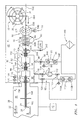
FIG. 1 is a partially schematic view of a coating system having a wire feed pressure lock system. -
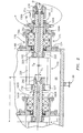
FIG. 2 is a partial enlarged view of an upstream portion of the pressure lock system ofFIG. 1 . -
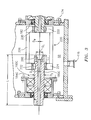
FIG. 3 is a partial enlarged view of a downstream portion of the pressure lock system ofFIG. 1 . - Like reference numbers and designations in the various drawings indicate like elements.
-
FIG. 1 shows a coating system for applying coatings tosubstrates 22. The coatings are generated at least partially from awire 24. Exemplary coatings are generated by vaporizing material from anend 26 of the wire in acoating chamber 28 having aninterior 30. The wire passes along awire path 500 from asource 32. The exemplary source comprises aspool 34 holding anaccumulation 36 of the wire. The wire passes along thewire path 500 in adownstream direction 504 from the source to the interior coating chamber. The exemplary wire source is in anexterior region 40 at a relatively high pressure P1 (e.g., ambient conditions). Theexemplary chamber interior 30 forms a second region at a pressure P2 lower than the first pressure P1. Avacuum system 42 may evacuate and maintain the coating chamber interior at P2. Depending upon circumstances, process gases may be introduced to the coating chamber from one or more gas sources (not shown). - Wire is driven from the spool along the wire path via a wire feed (drive)
mechanism 50. An exemplarywire feed mechanism 50 comprises a pair of opposed feed wheels orrolls first motor 56. Downstream of the wire feed mechanism, the wire passes through awire straightening mechanism 60. Downstream of the wire straightening mechanism, the wire and itspath 500 proceed essentially along a line oraxis 502. Theexemplary straightening mechanism 60 comprises a first group ofrollers 62A and a second group ofrollers 62B engaging the wire on opposite sides of the wire and its flowpath and streamwise alternating with each other. The exemplary rollers are freely mounted on acarrier 64 for rotation about respective axes. The carrier is mounted for rotation about anaxis 502 which is essentially locally coincident with the flowpath. Thecarrier 64 is coupled to amotor 66 to be driven by the motor around the axis 502 (e.g., an electric motor via chain, belt, or gear drive). As so far described, the source, feed mechanism, and straightening mechanism may represent an existing or yet-developed system. - In order to facilitate the pressure difference between P1 and P2 and/or prevent or substantially reduce infiltration of atmospheric contaminants to the coating chamber, the system 20 includes an isolation system (pressure lock system) 80. As is discussed further below, the exemplary isolation system includes two
intermediate chambers respective interiors interiors chambers first pumping system 90 is associated with thechamber 82 and includes amechanical pump 94. Thepump 94 is coupled to aport 96 of thechamber 82 via a valve 98 (e.g., a butterfly valve such as the model VBA100IE of the Varian Vacuum Products unit of Agilent Technologies, Inc., Santa Clara, California). The discharge of thepump 94 is coupled to an oil separator 100 (e.g., a mist separator) which may have an oil return to any associated pumps and may discharge to atmosphere. The exemplarysecond pumping system 92 has more pump stages than thefirst pumping system 90 to maintain the lower pressure P4. The exemplary second stage is formed by a mechanical pump 110 (e.g., similar to the pump 94) whose discharge is coupled in parallel to thesame separator 100 as that of thepump 94.Exemplary pumps 94 and 110 (e.g., Stokes Vacuum, Inc. (now Edwards Limited, Tewksbury, Massachusetts) multi-stage high capacity vacuum pump model 1736) each comprise two mechanical pumps in series (e.g., ablower piston pump - Each of the
pumps pressure gauge 99 and 111 (e.g., a Pirani gauge) along the line at the suction port thereof. The exemplarysecond system 92 further includes a second stage pump 112 (e.g., a diffusion pump such as the model VHS-6 of the Varian Vacuum Products unit of Agilent Technologies, Inc., Santa Clara, California). Theexemplary pump 112 is coupled to thepump 110 via a valve 113 (e.g., a SECUVAC™ model DN63 valve of Oerlikon Leybold Vacuum GmbH, Koln, Germany which functions as a safety valve by blocking access to the diffusion pump in the case of leakage). Similar to thevalve 98, a valve 114 (e.g., similar to 98) is positioned between thepump 112 and theassociated port 116 of the second chamber. Thechamber 88 may be similar to thechamber 86. In the exemplary embodiment, the diameter of theinlet 116 may be greater than that of 96 due to a higher vacuum in thechamber 84 than in 86. For further pressure measurement, the second chamber has attached thereto apressure gauge 120 which, similar to thegauges 99 and 111, may be a Pirani gauge. Additionally, thechamber 84 further includes acold cathode gauge 122 for pressure measurements at low pressures. - The
exemplary pump 110 is connected to thechamber 88 in two ways: directly via a first path/line 124 (having avalve 126 therein); and indirectly via asecond path 128 through thediffusion pump 112. In operation, at first thevalve 126 and first path are open while thevalves 113 and 114 and second path are closed and thepump 110 evacuates thesecond chamber 84 through thevalve 126 and first path. By having bothvalves 113 and 114 closed, thediffusion pump 112 is isolated for its protection. Then (when pressure in thechamber 84 drops below a threshold of about 10-3 Pa) thevalves 113 and 114 open (connecting thediffusion pump 112 to thechamber 84 and to the pump 110), and thevalve 126 closes, and thepump 110 begins to operate through thediffusion pump 112 operating in series. - In order to isolate each
chamber first interface 140 at anupstream wall 142 of thechamber 86; asecond interface 144 at awall 146 between thechambers third interface 148 at adownstream wall 150 of thechamber 84 between thechamber 84 and thechamber 28. The exemplary conduits are labeled 160A, 160B, and 160C. As is discussed further below, in operation each of the conduits 160 may rotate. Exemplary rotation is about a common axis as a unit. After entering thechamber 28, the wire may pass through one or more rotating ornon-rotating conduit 166 or 168 (e.g., cooling or mere guide conduits held to not rotate with the conduits 160). - Each of the exemplary conduits is mounted to its associated wall via a bearing and sealing
system 170. Each exemplary bearing and sealingsystem 170 includes a main body 172 having a mountingflange 174 secured to the associated wall. The main body has a bearing compartment carrying a pair of bearingassemblies lip seal 182 downstream of the bearings. The exemplary body further has a cover 184 covering the compartment (184A for the upstream conduit and 184B and 184C for the next two). - The exemplary
upstream conduit body 180A carries adrive gear 190 and thecover 184A carries aseal 192 engaged with the drive gear. The exemplary drive gear is secured against rotation via a key 194 and axially retained via anut 196 on a threaded portion of the conduit main body. Exemplary conduit body material is stainless steel with polished inner diameter aperture for reduced friction. At an upstream end of each conduit, the main body carries a hard anti-wear insert 200 (e.g., of metal ceramics such as BK6 (former Soviet designation for powder composite: 94W2C+6Co (wt.%), HRA>=87.5) or former Soviet TK15). The bodies of the second and third conduits directly carry this insert in an upstream compartment (e.g., via threaded engagement). The first conduit carries this insert via a similar engagement to acollar 210 which is, at its downstream end, threaded to the same externally threaded upstream end of the main body as is thenut 196. A gasket 212 (e.g., vacuum rubber or polymer such as PolyPak™ of Parker Hannifin Corp, Cleveland, Ohio) may seal the collar and insert relative to themain body 180A. - At their downstream ends, the
bodies conduit bodies cage structures 220 each having an upstream web orflange 222 and a downstream web orflange 224. Theflanges structure 220 allows communication between the interiors of the adjacent conduits and the interior 86 or 88 of thechamber such structure 220. The exemplary engagement features at upstream and downstream ends of thestructure 220 comprisekeys axis 502. Thus, rotation of thefirst conduit body 180A via thesprocket 190 drives all three of the conduits about theaxis 502 as a unit. The rotation of the conduits serves to reduce friction between wire and the conduits. An exemplary rotational speed is 1-60rpm, more narrowly 10-20rpm. The exemplary conduit upstream end portions protrude into the adjacent chamber or other space.FIG. 2 shows a protrusion length L1 for the second conduit upstream of the upstream face of theflange 224. Relative to a flush situation, this protrusion may help discourage leakage. Exemplary L1 is larger than D2 (e.g., at least twice as large as D2 and at least about as large as D1). - As noted above, exemplary means for driving rotation of the conduits drives the conduits as a unit. An exemplary such means comprises a
rotary actuator 240 coupled to the conduits via a transmission. An exemplary rotary actuator is an electric motor. An exemplary transmission comprises a belt or chain drive (e.g., having a drive pulley orgear 242 on the motor shaft and a driven pulley or gear (e.g., 190) secured relative to the conduits and driven via a belt or chain 244). - An exemplary overall length for each conduit is shown as L (which may differ conduit-to-conduit). An exemplary inner diameter of the conduit is shown as D2. In the exemplary embodiment, D2 is constant or essentially constant (e.g., offering no difference in airflow performance) over a majority of the associated length L. For example, the exemplary embodiment D2 is constant along a region where the conduit body is directly exposed to the wire and diverges upstream along a portion of the insert. In the exemplary implementation, the insert has a
frustoconical segment surface 260 having a downstream portion at D2 and transitioning to an upstream/opening having a diameter of D1. An exemplary half angle of this portion is shown as θ. An exemplary diameter (or other largest transverse dimension for a non-circular cross-section) of the wire is shown as DW. Exemplary DW is 0.5-3mm, more particularly 1-2mm with a particular example of a steel or titanium wire of 1.4-1.6mm. Exemplary D2 is 1-6mm, more particularly 1.5-3mm or 2mm in the example. Exemplary L is 50-250mm, more particularly 100-200mm or about 130mm in the example. Whereas longer lengths may provide better pressure isolation, they increase manufacturing costs (e.g., of polishing the interior of the conduit). An exemplary ratio of D2 to DW is 2:1.4 to 2:1.6, more broadly 2:1.3 to 2:1.8. The outer diameter D3 of the conduit body may be selected for mechanical strength of the conduit in view of any desired D2, L, and rotational speed and available bearings and seals. - One or more embodiments have been described. Nevertheless, it will be understood that various modifications may be made. For example, when implemented in the remanufacturing of an existing system or the reengineering of a configuration of such system, details of the existing system or configuration may influence details of any particular implementation. Accordingly, other embodiments are within the scope of the following claims.
Claims (15)
- A pressure lock system for passing a wire (24) along a wire path (504) from a wire source (32) at a high pressure first region (40) to a destination at a low pressure second region (30), the system comprising:a pressure lock chamber (82);a first conduit (160A) having an interior positioned to pass the wire (24) along the wire path (504) and mounted for rotation;a second conduit (160B) having an interior positioned to pass the wire (24) from the pressure lock chamber (82) downstream of the first conduit (160A) and mounted for rotation;means (240) for driving rotation of the first conduit (160A) and the second conduit (160B); andmeans (90) for maintaining a pressure (P3) of the pressure lock chamber (82) lower than a pressure (P1) of the first region (40).
- The system of claim 1 wherein the first conduit (160A) comprises a body (180A) and an inlet end piece (200) harder than the body (180A).
- The system of claim 1 or 2, wherein:the means for driving rotation comprises a motor (240) coupled to the conduits (160A, 160B) to drive said rotation; andthe means (90) for maintaining comprises at least one pump (94) coupled to the pressure lock chamber (82).
- The system of any preceding claim, further comprising:a second pressure lock chamber (84); anda third conduit (160C) having an interior positioned along the wire path (504) to pass the wire (24) downstream of the second conduit (160B) and mounted for rotation.
- The system of claim 4, wherein:the second conduit (160B) is positioned to pass the wire (24) from the pressure lock chamber (82) to the second pressure lock chamber (84); andthe first conduit (160A), second conduit (160B), and third conduit (160C) are mounted for coaxial rotation about a single axis (502).
- The system of claim 4 or 5, wherein the means (240) for driving rotation is coupled to the first conduit (160A), second conduit (160B), and third conduit (160C) to drive their rotation as a unit about the single axis (502).
- The system of any of claims 4 to 6, further comprising a fourth conduit (168), downstream of the third conduit (160C) along the wire flowpath and held to not rotate with the first, second, and third conduits (160A, 160B, 160C).
- The system of claim 7, further comprising a fifth conduit (166), downstream of the fourth conduit (168), and being a terminal conduit.
- A wire delivery system comprising:the system of any of claims 4 to 8;said wire source (32) supplying the wire (24); anda wire straightener (60) between the source (32) and the first conduit (160A).
- A vacuum coating system comprising:the system of any preceding claim, wherein the wire source (32) is at the high pressure first region (40); anda coater comprising:a coating chamber (28) having an interior (30) defining the low pressure second region; andmeans for forming a coating from the wire (24) delivered to the coating chamber (28).
- The system of any preceding claim, wherein the high pressure first region (40) is at ambient conditions.
- A method for pressure-isolating a wire feed system to isolate a wire source (32) at a high pressure first region (40) from a destination at a low pressure second region (30), the method comprising:passing the wire (24) through a rotating first conduit (160A) into a pressure lock chamber (82);passing the wire (24) through a rotating second conduit (160B) from the pressure lock chamber (82); andmaintaining a pressure (P3) of the pressure lock chamber (82) lower than a pressure (P1) of the first region (40).
- The method of claim 12, wherein the wire (24) is passed through said rotating second conduit (160B) into a second pressure lock chamber (84) and the method further comprises:passing the wire (24) through a rotating third conduit (160C) from the second pressure lock chamber (84); and optionally maintaining a pressure (P4) of the second pressure lock chamber (84) lower than the pressure (P3) of the pressure lock chamber (82), wherein optionally the first conduit (160A), second conduit (160B), and third conduit (160C) are rotated as a unit.
- A method for operating the system of claim 9 or 10 or 11 when dependent upon claim 9, comprising simultaneously:driving a rotation of the combined first conduit (160A), second conduit (160B), and third conduit (160C);maintaining the pressure lock chamber (82) at a third pressure (P3) below the first pressure (P1);maintaining the second pressure lock chamber (84) at a fourth pressure (P4) below the third pressure (P3);maintaining the coating chamber (28) at said second pressure (P2), below the first pressure (P1) and below the fourth pressure (P4);feeding the wire (24) from the wire source (32) to the straightener (60);straightening the wire (24) by the straightener (60);passing the wire (24) through the first conduit (160A), second conduit (160B), and third conduit (160C) into the coating chamber (28); andforming a coating from the wire (24).
- The method of claim 14, wherein:the forming of the coating comprises vaporizing the wire (24); andthe method further comprises passing the wire (24) through a liquid-cooled fourth conduit (168) downstream of the third conduit (160C).
Applications Claiming Priority (1)
| Application Number | Priority Date | Filing Date | Title |
|---|---|---|---|
| US12/981,667 US8920566B2 (en) | 2010-12-30 | 2010-12-30 | Wire feed pressure lock system |
Publications (3)
| Publication Number | Publication Date |
|---|---|
| EP2471733A2 true EP2471733A2 (en) | 2012-07-04 |
| EP2471733A3 EP2471733A3 (en) | 2013-01-16 |
| EP2471733B1 EP2471733B1 (en) | 2015-01-21 |
Family
ID=45464284
Family Applications (1)
| Application Number | Title | Priority Date | Filing Date |
|---|---|---|---|
| EP20110194780 Active EP2471733B1 (en) | 2010-12-30 | 2011-12-21 | Wire feed pressure lock system |
Country Status (3)
| Country | Link |
|---|---|
| US (1) | US8920566B2 (en) |
| EP (1) | EP2471733B1 (en) |
| UA (1) | UA108355C2 (en) |
Cited By (4)
| Publication number | Priority date | Publication date | Assignee | Title |
|---|---|---|---|---|
| CN107370083A (en) * | 2017-06-27 | 2017-11-21 | 铜陵市铜都特种线缆有限公司 | A kind of device being used for cable processing |
| CN109072414A (en) * | 2016-05-03 | 2018-12-21 | 塔塔钢铁荷兰科技有限责任公司 | For the device to evaporator device supply fluent material |
| CN110759164A (en) * | 2019-11-08 | 2020-02-07 | 湖南盛世电线电缆有限公司 | Enameled wire paying-off machine |
| CN115673168A (en) * | 2022-11-10 | 2023-02-03 | 连云港伟泽材料科技有限公司 | Steel bar cutting machine |
Families Citing this family (8)
| Publication number | Priority date | Publication date | Assignee | Title |
|---|---|---|---|---|
| US9038479B2 (en) * | 2012-07-27 | 2015-05-26 | United Technologies Corporation | Compression fitting |
| JP6265138B2 (en) * | 2013-01-31 | 2018-01-24 | 株式会社ニコン | Processing apparatus, injection processing method, and electrode material manufacturing method |
| JP6588058B2 (en) * | 2017-08-04 | 2019-10-09 | 矢崎総業株式会社 | Electric wire straightening device |
| CN111135975B (en) * | 2020-02-11 | 2020-12-22 | 国网黑龙江省电力有限公司电力科学研究院 | A cable spraying and straightening device |
| CN112338107B (en) * | 2020-09-23 | 2023-03-31 | 国网山东省电力公司德州市陵城区供电公司 | Convenient to use's power cable corrector |
| DE102021103561B3 (en) * | 2021-02-16 | 2022-03-24 | Rittal Gmbh & Co. Kg | Arrangement for the transport of a wire from a wire assembly machine to a delivery point |
| CN113042652B (en) * | 2021-05-06 | 2024-11-19 | 河南省韧牌牧业机械设备有限公司 | A compact metal wire straightening shaft and long arc straightening die |
| CN113634690B (en) * | 2021-10-12 | 2021-12-24 | 南通泽云机械有限公司 | Cutting equipment for port machine part production |
Family Cites Families (21)
| Publication number | Priority date | Publication date | Assignee | Title |
|---|---|---|---|---|
| GB763541A (en) | 1953-09-29 | 1956-12-12 | Siemens Ag | Improvements in or relating to apparatus for the continuous treatment in vacuo of wire or other strip-like material |
| US3024965A (en) | 1957-10-08 | 1962-03-13 | Milleron Norman | Apparatus for vacuum deposition of metals |
| US3467058A (en) | 1965-12-03 | 1969-09-16 | United States Steel Corp | Apparatus for vaporizing metal |
| FR1529707A (en) | 1967-04-13 | 1968-06-21 | Comp Generale Electricite | Fine wire guide device |
| BE714903A (en) | 1967-05-10 | 1968-09-30 | ||
| US3562002A (en) * | 1968-04-24 | 1971-02-09 | Air Reduction | Method and apparatus for vapor deposition |
| BE795116A (en) | 1972-02-08 | 1973-05-29 | Cockerill | EVAPORATION BATH FEEDING PROCESS |
| GB1512837A (en) | 1975-06-24 | 1978-06-01 | Electricity Council | Seals for the passage of wire between regions of different pressure |
| US3952568A (en) | 1974-09-04 | 1976-04-27 | The Electricity Council | Vacuum processing of rod, wire or strip material |
| BG23055A1 (en) * | 1975-09-24 | 1977-07-12 | ||
| BG23278A1 (en) * | 1975-09-24 | 1977-08-10 | ||
| SE7712597L (en) * | 1976-11-24 | 1978-05-25 | Zuv Progress | PLANETARY FEEDING DEVICE FOR PLANETARY RELEASE WITH ADJUSTMENT OF THE EXHAUST FORCE |
| JPS54160567A (en) | 1978-06-09 | 1979-12-19 | Hitachi Ltd | Vacuum deposition evaporator |
| JPS60211071A (en) | 1984-04-04 | 1985-10-23 | Matsushita Electric Ind Co Ltd | Vacuum depositing apparatus |
| US5321792A (en) * | 1991-07-31 | 1994-06-14 | Leybold Aktiengesellschaft | Apparatus for the continuous feeding of wire to an evaporator boat |
| JPH0633226A (en) | 1992-07-21 | 1994-02-08 | Tdk Corp | Raw material metal supply method in vacuum deposition |
| IL102935A (en) * | 1992-08-25 | 1996-10-31 | Planetics Welding Systems Ltd | Planetary feeder heads |
| JP2995372B2 (en) | 1993-01-20 | 1999-12-27 | 三菱電機株式会社 | Operation information display device |
| US6090457A (en) | 1997-10-21 | 2000-07-18 | Sanyo Vaccum Industries Co. Ltd. | Process of making a thin film |
| DE19923654A1 (en) | 1999-05-22 | 2000-11-23 | Leybold Systems Gmbh | Vaporizer arranged in a glass bulb of a vacuum deposition device has an inlet for wire material to be vaporized, a central heating region, and an inlet for the wire material |
| GB2410714A (en) | 2004-02-07 | 2005-08-10 | Aquasium Technology Ltd | Manufacturing three-dimensional products using build-up electron beam welding |
-
2010
- 2010-12-30 US US12/981,667 patent/US8920566B2/en active Active
-
2011
- 2011-11-15 UA UAA201113435A patent/UA108355C2/en unknown
- 2011-12-21 EP EP20110194780 patent/EP2471733B1/en active Active
Non-Patent Citations (1)
| Title |
|---|
| None |
Cited By (5)
| Publication number | Priority date | Publication date | Assignee | Title |
|---|---|---|---|---|
| CN109072414A (en) * | 2016-05-03 | 2018-12-21 | 塔塔钢铁荷兰科技有限责任公司 | For the device to evaporator device supply fluent material |
| CN107370083A (en) * | 2017-06-27 | 2017-11-21 | 铜陵市铜都特种线缆有限公司 | A kind of device being used for cable processing |
| CN110759164A (en) * | 2019-11-08 | 2020-02-07 | 湖南盛世电线电缆有限公司 | Enameled wire paying-off machine |
| CN115673168A (en) * | 2022-11-10 | 2023-02-03 | 连云港伟泽材料科技有限公司 | Steel bar cutting machine |
| CN115673168B (en) * | 2022-11-10 | 2024-06-04 | 连云港伟泽材料科技有限公司 | A steel bar cutting machine |
Also Published As
| Publication number | Publication date |
|---|---|
| US8920566B2 (en) | 2014-12-30 |
| EP2471733A3 (en) | 2013-01-16 |
| US20120171382A1 (en) | 2012-07-05 |
| EP2471733B1 (en) | 2015-01-21 |
| UA108355C2 (en) | 2015-04-27 |
Similar Documents
| Publication | Publication Date | Title |
|---|---|---|
| EP2471733B1 (en) | Wire feed pressure lock system | |
| KR100730073B1 (en) | Evacuating apparatus | |
| US9239061B2 (en) | Compressor employing a dry gas seal | |
| KR101430848B1 (en) | Pump | |
| EP2516863B1 (en) | Dry vacuum pump with purge gas system and method of purging | |
| EP2434156A1 (en) | Dry vacuum pump | |
| US5356275A (en) | Device for supplying a multi-stage dry-running vacuum pump with inert gas | |
| US20120094074A1 (en) | Dlc film-forming method and dlc film | |
| KR20170037946A (en) | Dry pump and exhaust gas treatment method | |
| EP2715139B1 (en) | Vacuum pump | |
| EP1475557A1 (en) | Oil film sealing device for a rotating shaft | |
| EP2374914B1 (en) | A device for sealing a chamber inlet or a chamber outlet for a flexible substrate; substrate processing apparatus, and method for assembling such a device | |
| JP5717751B2 (en) | Corrosion-resistant shaft seal device for vacuum pumps | |
| US10655626B2 (en) | Liquid ring pump | |
| CN102906471B (en) | Rotation device provided with seal structure | |
| GB2440542A (en) | Vacuum pump gearbox purge gas arrangement | |
| JP2010229832A (en) | Dry vacuum pump and process chamber decompression method using the same | |
| EP3236080B1 (en) | Rotary machine system | |
| US20180085799A1 (en) | Exhaust system, semiconductor manufacturing equipment, and method for operating the exhaust system | |
| GB2437968A (en) | Vacuum pumping arrangement for evacuating a plurality of process chambers | |
| JP4131754B2 (en) | Vacuum valve for automatic delay vent and automatic delay vent mechanism of vacuum equipment using the same | |
| EP3800356B1 (en) | Coating for compressor outlet housing | |
| WO2024235915A1 (en) | Vacuum pump |
Legal Events
| Date | Code | Title | Description |
|---|---|---|---|
| AK | Designated contracting states |
Kind code of ref document: A2 Designated state(s): AL AT BE BG CH CY CZ DE DK EE ES FI FR GB GR HR HU IE IS IT LI LT LU LV MC MK MT NL NO PL PT RO RS SE SI SK SM TR |
|
| AX | Request for extension of the european patent |
Extension state: BA ME |
|
| PUAI | Public reference made under article 153(3) epc to a published international application that has entered the european phase |
Free format text: ORIGINAL CODE: 0009012 |
|
| PUAL | Search report despatched |
Free format text: ORIGINAL CODE: 0009013 |
|
| RIC1 | Information provided on ipc code assigned before grant |
Ipc: C23C 14/24 20060101ALI20121121BHEP Ipc: B65H 57/26 20060101ALI20121121BHEP Ipc: B65H 57/12 20060101AFI20121121BHEP |
|
| RIC1 | Information provided on ipc code assigned before grant |
Ipc: C23C 14/24 20060101ALI20121123BHEP Ipc: B65H 57/12 20060101AFI20121123BHEP Ipc: B65H 57/26 20060101ALI20121123BHEP |
|
| AK | Designated contracting states |
Kind code of ref document: A3 Designated state(s): AL AT BE BG CH CY CZ DE DK EE ES FI FR GB GR HR HU IE IS IT LI LT LU LV MC MK MT NL NO PL PT RO RS SE SI SK SM TR |
|
| AX | Request for extension of the european patent |
Extension state: BA ME |
|
| RIC1 | Information provided on ipc code assigned before grant |
Ipc: B65H 57/12 20060101AFI20121211BHEP Ipc: B65H 57/26 20060101ALI20121211BHEP Ipc: C23C 14/24 20060101ALI20121211BHEP |
|
| 17P | Request for examination filed |
Effective date: 20130624 |
|
| RBV | Designated contracting states (corrected) |
Designated state(s): AL AT BE BG CH CY CZ DE DK EE ES FI FR GB GR HR HU IE IS IT LI LT LU LV MC MK MT NL NO PL PT RO RS SE SI SK SM TR |
|
| GRAP | Despatch of communication of intention to grant a patent |
Free format text: ORIGINAL CODE: EPIDOSNIGR1 |
|
| INTG | Intention to grant announced |
Effective date: 20140214 |
|
| GRAP | Despatch of communication of intention to grant a patent |
Free format text: ORIGINAL CODE: EPIDOSNIGR1 |
|
| INTG | Intention to grant announced |
Effective date: 20140704 |
|
| GRAS | Grant fee paid |
Free format text: ORIGINAL CODE: EPIDOSNIGR3 |
|
| GRAA | (expected) grant |
Free format text: ORIGINAL CODE: 0009210 |
|
| AK | Designated contracting states |
Kind code of ref document: B1 Designated state(s): AL AT BE BG CH CY CZ DE DK EE ES FI FR GB GR HR HU IE IS IT LI LT LU LV MC MK MT NL NO PL PT RO RS SE SI SK SM TR |
|
| REG | Reference to a national code |
Ref country code: GB Ref legal event code: FG4D |
|
| REG | Reference to a national code |
Ref country code: CH Ref legal event code: EP |
|
| REG | Reference to a national code |
Ref country code: IE Ref legal event code: FG4D |
|
| REG | Reference to a national code |
Ref country code: DE Ref legal event code: R096 Ref document number: 602011013294 Country of ref document: DE Effective date: 20150305 |
|
| REG | Reference to a national code |
Ref country code: AT Ref legal event code: REF Ref document number: 709066 Country of ref document: AT Kind code of ref document: T Effective date: 20150315 |
|
| REG | Reference to a national code |
Ref country code: NL Ref legal event code: VDEP Effective date: 20150121 |
|
| REG | Reference to a national code |
Ref country code: AT Ref legal event code: MK05 Ref document number: 709066 Country of ref document: AT Kind code of ref document: T Effective date: 20150121 |
|
| REG | Reference to a national code |
Ref country code: LT Ref legal event code: MG4D |
|
| PG25 | Lapsed in a contracting state [announced via postgrant information from national office to epo] |
Ref country code: FI Free format text: LAPSE BECAUSE OF FAILURE TO SUBMIT A TRANSLATION OF THE DESCRIPTION OR TO PAY THE FEE WITHIN THE PRESCRIBED TIME-LIMIT Effective date: 20150121 Ref country code: BG Free format text: LAPSE BECAUSE OF FAILURE TO SUBMIT A TRANSLATION OF THE DESCRIPTION OR TO PAY THE FEE WITHIN THE PRESCRIBED TIME-LIMIT Effective date: 20150421 Ref country code: HR Free format text: LAPSE BECAUSE OF FAILURE TO SUBMIT A TRANSLATION OF THE DESCRIPTION OR TO PAY THE FEE WITHIN THE PRESCRIBED TIME-LIMIT Effective date: 20150121 Ref country code: SE Free format text: LAPSE BECAUSE OF FAILURE TO SUBMIT A TRANSLATION OF THE DESCRIPTION OR TO PAY THE FEE WITHIN THE PRESCRIBED TIME-LIMIT Effective date: 20150121 Ref country code: ES Free format text: LAPSE BECAUSE OF FAILURE TO SUBMIT A TRANSLATION OF THE DESCRIPTION OR TO PAY THE FEE WITHIN THE PRESCRIBED TIME-LIMIT Effective date: 20150121 Ref country code: LT Free format text: LAPSE BECAUSE OF FAILURE TO SUBMIT A TRANSLATION OF THE DESCRIPTION OR TO PAY THE FEE WITHIN THE PRESCRIBED TIME-LIMIT Effective date: 20150121 Ref country code: NO Free format text: LAPSE BECAUSE OF FAILURE TO SUBMIT A TRANSLATION OF THE DESCRIPTION OR TO PAY THE FEE WITHIN THE PRESCRIBED TIME-LIMIT Effective date: 20150421 |
|
| PG25 | Lapsed in a contracting state [announced via postgrant information from national office to epo] |
Ref country code: AT Free format text: LAPSE BECAUSE OF FAILURE TO SUBMIT A TRANSLATION OF THE DESCRIPTION OR TO PAY THE FEE WITHIN THE PRESCRIBED TIME-LIMIT Effective date: 20150121 Ref country code: GR Free format text: LAPSE BECAUSE OF FAILURE TO SUBMIT A TRANSLATION OF THE DESCRIPTION OR TO PAY THE FEE WITHIN THE PRESCRIBED TIME-LIMIT Effective date: 20150422 Ref country code: NL Free format text: LAPSE BECAUSE OF FAILURE TO SUBMIT A TRANSLATION OF THE DESCRIPTION OR TO PAY THE FEE WITHIN THE PRESCRIBED TIME-LIMIT Effective date: 20150121 Ref country code: PL Free format text: LAPSE BECAUSE OF FAILURE TO SUBMIT A TRANSLATION OF THE DESCRIPTION OR TO PAY THE FEE WITHIN THE PRESCRIBED TIME-LIMIT Effective date: 20150121 Ref country code: IS Free format text: LAPSE BECAUSE OF FAILURE TO SUBMIT A TRANSLATION OF THE DESCRIPTION OR TO PAY THE FEE WITHIN THE PRESCRIBED TIME-LIMIT Effective date: 20150521 Ref country code: RS Free format text: LAPSE BECAUSE OF FAILURE TO SUBMIT A TRANSLATION OF THE DESCRIPTION OR TO PAY THE FEE WITHIN THE PRESCRIBED TIME-LIMIT Effective date: 20150121 Ref country code: LV Free format text: LAPSE BECAUSE OF FAILURE TO SUBMIT A TRANSLATION OF THE DESCRIPTION OR TO PAY THE FEE WITHIN THE PRESCRIBED TIME-LIMIT Effective date: 20150121 |
|
| REG | Reference to a national code |
Ref country code: DE Ref legal event code: R097 Ref document number: 602011013294 Country of ref document: DE |
|
| PG25 | Lapsed in a contracting state [announced via postgrant information from national office to epo] |
Ref country code: RO Free format text: LAPSE BECAUSE OF FAILURE TO SUBMIT A TRANSLATION OF THE DESCRIPTION OR TO PAY THE FEE WITHIN THE PRESCRIBED TIME-LIMIT Effective date: 20150121 Ref country code: CZ Free format text: LAPSE BECAUSE OF FAILURE TO SUBMIT A TRANSLATION OF THE DESCRIPTION OR TO PAY THE FEE WITHIN THE PRESCRIBED TIME-LIMIT Effective date: 20150121 Ref country code: DK Free format text: LAPSE BECAUSE OF FAILURE TO SUBMIT A TRANSLATION OF THE DESCRIPTION OR TO PAY THE FEE WITHIN THE PRESCRIBED TIME-LIMIT Effective date: 20150121 Ref country code: SK Free format text: LAPSE BECAUSE OF FAILURE TO SUBMIT A TRANSLATION OF THE DESCRIPTION OR TO PAY THE FEE WITHIN THE PRESCRIBED TIME-LIMIT Effective date: 20150121 Ref country code: EE Free format text: LAPSE BECAUSE OF FAILURE TO SUBMIT A TRANSLATION OF THE DESCRIPTION OR TO PAY THE FEE WITHIN THE PRESCRIBED TIME-LIMIT Effective date: 20150121 |
|
| PLBE | No opposition filed within time limit |
Free format text: ORIGINAL CODE: 0009261 |
|
| STAA | Information on the status of an ep patent application or granted ep patent |
Free format text: STATUS: NO OPPOSITION FILED WITHIN TIME LIMIT |
|
| 26N | No opposition filed |
Effective date: 20151022 |
|
| PG25 | Lapsed in a contracting state [announced via postgrant information from national office to epo] |
Ref country code: IT Free format text: LAPSE BECAUSE OF FAILURE TO SUBMIT A TRANSLATION OF THE DESCRIPTION OR TO PAY THE FEE WITHIN THE PRESCRIBED TIME-LIMIT Effective date: 20150121 |
|
| PG25 | Lapsed in a contracting state [announced via postgrant information from national office to epo] |
Ref country code: SI Free format text: LAPSE BECAUSE OF FAILURE TO SUBMIT A TRANSLATION OF THE DESCRIPTION OR TO PAY THE FEE WITHIN THE PRESCRIBED TIME-LIMIT Effective date: 20150121 |
|
| PG25 | Lapsed in a contracting state [announced via postgrant information from national office to epo] |
Ref country code: BE Free format text: LAPSE BECAUSE OF FAILURE TO SUBMIT A TRANSLATION OF THE DESCRIPTION OR TO PAY THE FEE WITHIN THE PRESCRIBED TIME-LIMIT Effective date: 20150121 |
|
| PG25 | Lapsed in a contracting state [announced via postgrant information from national office to epo] |
Ref country code: MC Free format text: LAPSE BECAUSE OF FAILURE TO SUBMIT A TRANSLATION OF THE DESCRIPTION OR TO PAY THE FEE WITHIN THE PRESCRIBED TIME-LIMIT Effective date: 20150121 Ref country code: LU Free format text: LAPSE BECAUSE OF FAILURE TO SUBMIT A TRANSLATION OF THE DESCRIPTION OR TO PAY THE FEE WITHIN THE PRESCRIBED TIME-LIMIT Effective date: 20151221 |
|
| REG | Reference to a national code |
Ref country code: CH Ref legal event code: PL |
|
| REG | Reference to a national code |
Ref country code: IE Ref legal event code: MM4A |
|
| REG | Reference to a national code |
Ref country code: FR Ref legal event code: ST Effective date: 20160831 |
|
| PG25 | Lapsed in a contracting state [announced via postgrant information from national office to epo] |
Ref country code: IE Free format text: LAPSE BECAUSE OF NON-PAYMENT OF DUE FEES Effective date: 20151221 Ref country code: CH Free format text: LAPSE BECAUSE OF NON-PAYMENT OF DUE FEES Effective date: 20151231 Ref country code: LI Free format text: LAPSE BECAUSE OF NON-PAYMENT OF DUE FEES Effective date: 20151231 |
|
| PG25 | Lapsed in a contracting state [announced via postgrant information from national office to epo] |
Ref country code: FR Free format text: LAPSE BECAUSE OF NON-PAYMENT OF DUE FEES Effective date: 20151231 |
|
| PG25 | Lapsed in a contracting state [announced via postgrant information from national office to epo] |
Ref country code: HU Free format text: LAPSE BECAUSE OF FAILURE TO SUBMIT A TRANSLATION OF THE DESCRIPTION OR TO PAY THE FEE WITHIN THE PRESCRIBED TIME-LIMIT; INVALID AB INITIO Effective date: 20111221 Ref country code: SM Free format text: LAPSE BECAUSE OF FAILURE TO SUBMIT A TRANSLATION OF THE DESCRIPTION OR TO PAY THE FEE WITHIN THE PRESCRIBED TIME-LIMIT Effective date: 20150121 |
|
| PG25 | Lapsed in a contracting state [announced via postgrant information from national office to epo] |
Ref country code: CY Free format text: LAPSE BECAUSE OF FAILURE TO SUBMIT A TRANSLATION OF THE DESCRIPTION OR TO PAY THE FEE WITHIN THE PRESCRIBED TIME-LIMIT Effective date: 20150121 |
|
| REG | Reference to a national code |
Ref country code: DE Ref legal event code: R082 Ref document number: 602011013294 Country of ref document: DE Representative=s name: SCHMITT-NILSON SCHRAUD WAIBEL WOHLFROM PATENTA, DE |
|
| REG | Reference to a national code |
Ref country code: DE Ref legal event code: R082 Ref document number: 602011013294 Country of ref document: DE Representative=s name: SCHMITT-NILSON SCHRAUD WAIBEL WOHLFROM PATENTA, DE Ref country code: DE Ref legal event code: R081 Ref document number: 602011013294 Country of ref document: DE Owner name: UNITED TECHNOLOGIES CORP. (N.D.GES.D. STAATES , US Free format text: FORMER OWNER: UNITED TECHNOLOGIES CORPORATION, HARTFORD, CONN., US |
|
| PG25 | Lapsed in a contracting state [announced via postgrant information from national office to epo] |
Ref country code: MT Free format text: LAPSE BECAUSE OF FAILURE TO SUBMIT A TRANSLATION OF THE DESCRIPTION OR TO PAY THE FEE WITHIN THE PRESCRIBED TIME-LIMIT Effective date: 20150121 Ref country code: TR Free format text: LAPSE BECAUSE OF FAILURE TO SUBMIT A TRANSLATION OF THE DESCRIPTION OR TO PAY THE FEE WITHIN THE PRESCRIBED TIME-LIMIT Effective date: 20150121 |
|
| PG25 | Lapsed in a contracting state [announced via postgrant information from national office to epo] |
Ref country code: PT Free format text: LAPSE BECAUSE OF FAILURE TO SUBMIT A TRANSLATION OF THE DESCRIPTION OR TO PAY THE FEE WITHIN THE PRESCRIBED TIME-LIMIT Effective date: 20150121 Ref country code: MK Free format text: LAPSE BECAUSE OF FAILURE TO SUBMIT A TRANSLATION OF THE DESCRIPTION OR TO PAY THE FEE WITHIN THE PRESCRIBED TIME-LIMIT Effective date: 20150121 |
|
| PG25 | Lapsed in a contracting state [announced via postgrant information from national office to epo] |
Ref country code: AL Free format text: LAPSE BECAUSE OF FAILURE TO SUBMIT A TRANSLATION OF THE DESCRIPTION OR TO PAY THE FEE WITHIN THE PRESCRIBED TIME-LIMIT Effective date: 20150121 |
|
| REG | Reference to a national code |
Ref country code: DE Ref legal event code: R081 Ref document number: 602011013294 Country of ref document: DE Owner name: RAYTHEON TECHNOLOGIES CORPORATION (N.D.GES.D.S, US Free format text: FORMER OWNER: UNITED TECHNOLOGIES CORP. (N.D.GES.D. STAATES DELAWARE), FARMINGTON, CONN., US Ref country code: DE Ref legal event code: R081 Ref document number: 602011013294 Country of ref document: DE Owner name: RTX CORPORATION (N.D.GES.D. STAATES DELAWARE),, US Free format text: FORMER OWNER: UNITED TECHNOLOGIES CORP. (N.D.GES.D. STAATES DELAWARE), FARMINGTON, CONN., US |
|
| P01 | Opt-out of the competence of the unified patent court (upc) registered |
Effective date: 20230520 |
|
| REG | Reference to a national code |
Ref country code: DE Ref legal event code: R081 Ref document number: 602011013294 Country of ref document: DE Owner name: RTX CORPORATION (N.D.GES.D. STAATES DELAWARE),, US Free format text: FORMER OWNER: RAYTHEON TECHNOLOGIES CORPORATION (N.D.GES.D.STAATES DELAWARE), ARLINGTON, VA, US |
|
| PGFP | Annual fee paid to national office [announced via postgrant information from national office to epo] |
Ref country code: DE Payment date: 20251126 Year of fee payment: 15 |
|
| PGFP | Annual fee paid to national office [announced via postgrant information from national office to epo] |
Ref country code: GB Payment date: 20251119 Year of fee payment: 15 |