EP2471631A2 - A system for forming a labyrinth seal - Google Patents
A system for forming a labyrinth seal Download PDFInfo
- Publication number
- EP2471631A2 EP2471631A2 EP12162545A EP12162545A EP2471631A2 EP 2471631 A2 EP2471631 A2 EP 2471631A2 EP 12162545 A EP12162545 A EP 12162545A EP 12162545 A EP12162545 A EP 12162545A EP 2471631 A2 EP2471631 A2 EP 2471631A2
- Authority
- EP
- European Patent Office
- Prior art keywords
- coolant
- grinding
- labyrinth seal
- grinding wheels
- turbine blade
- Prior art date
- Legal status (The legal status is an assumption and is not a legal conclusion. Google has not performed a legal analysis and makes no representation as to the accuracy of the status listed.)
- Granted
Links
- 239000002826 coolant Substances 0.000 claims abstract description 39
- 229910052582 BN Inorganic materials 0.000 claims description 2
- PZNSFCLAULLKQX-UHFFFAOYSA-N Boron nitride Chemical compound N#B PZNSFCLAULLKQX-UHFFFAOYSA-N 0.000 claims description 2
- 238000000034 method Methods 0.000 description 18
- 238000003754 machining Methods 0.000 description 8
- 238000005520 cutting process Methods 0.000 description 4
- 238000005516 engineering process Methods 0.000 description 3
- PXHVJJICTQNCMI-UHFFFAOYSA-N Nickel Chemical compound [Ni] PXHVJJICTQNCMI-UHFFFAOYSA-N 0.000 description 2
- 229910000531 Co alloy Inorganic materials 0.000 description 1
- 239000012530 fluid Substances 0.000 description 1
- 238000004519 manufacturing process Methods 0.000 description 1
- 230000013011 mating Effects 0.000 description 1
- 238000005272 metallurgy Methods 0.000 description 1
- 229910052759 nickel Inorganic materials 0.000 description 1
- 230000008092 positive effect Effects 0.000 description 1
- XLYOFNOQVPJJNP-UHFFFAOYSA-N water Substances O XLYOFNOQVPJJNP-UHFFFAOYSA-N 0.000 description 1
Images






Classifications
-
- B—PERFORMING OPERATIONS; TRANSPORTING
- B24—GRINDING; POLISHING
- B24B—MACHINES, DEVICES, OR PROCESSES FOR GRINDING OR POLISHING; DRESSING OR CONDITIONING OF ABRADING SURFACES; FEEDING OF GRINDING, POLISHING, OR LAPPING AGENTS
- B24B19/00—Single-purpose machines or devices for particular grinding operations not covered by any other main group
- B24B19/14—Single-purpose machines or devices for particular grinding operations not covered by any other main group for grinding turbine blades, propeller blades or the like
-
- B—PERFORMING OPERATIONS; TRANSPORTING
- B24—GRINDING; POLISHING
- B24B—MACHINES, DEVICES, OR PROCESSES FOR GRINDING OR POLISHING; DRESSING OR CONDITIONING OF ABRADING SURFACES; FEEDING OF GRINDING, POLISHING, OR LAPPING AGENTS
- B24B41/00—Component parts such as frames, beds, carriages, headstocks
- B24B41/06—Work supports, e.g. adjustable steadies
-
- B—PERFORMING OPERATIONS; TRANSPORTING
- B24—GRINDING; POLISHING
- B24B—MACHINES, DEVICES, OR PROCESSES FOR GRINDING OR POLISHING; DRESSING OR CONDITIONING OF ABRADING SURFACES; FEEDING OF GRINDING, POLISHING, OR LAPPING AGENTS
- B24B57/00—Devices for feeding, applying, grading or recovering grinding, polishing or lapping agents
- B24B57/02—Devices for feeding, applying, grading or recovering grinding, polishing or lapping agents for feeding of fluid, sprayed, pulverised, or liquefied grinding, polishing or lapping agents
-
- Y—GENERAL TAGGING OF NEW TECHNOLOGICAL DEVELOPMENTS; GENERAL TAGGING OF CROSS-SECTIONAL TECHNOLOGIES SPANNING OVER SEVERAL SECTIONS OF THE IPC; TECHNICAL SUBJECTS COVERED BY FORMER USPC CROSS-REFERENCE ART COLLECTIONS [XRACs] AND DIGESTS
- Y10—TECHNICAL SUBJECTS COVERED BY FORMER USPC
- Y10T—TECHNICAL SUBJECTS COVERED BY FORMER US CLASSIFICATION
- Y10T29/00—Metal working
- Y10T29/49—Method of mechanical manufacture
- Y10T29/49316—Impeller making
-
- Y—GENERAL TAGGING OF NEW TECHNOLOGICAL DEVELOPMENTS; GENERAL TAGGING OF CROSS-SECTIONAL TECHNOLOGIES SPANNING OVER SEVERAL SECTIONS OF THE IPC; TECHNICAL SUBJECTS COVERED BY FORMER USPC CROSS-REFERENCE ART COLLECTIONS [XRACs] AND DIGESTS
- Y10—TECHNICAL SUBJECTS COVERED BY FORMER USPC
- Y10T—TECHNICAL SUBJECTS COVERED BY FORMER US CLASSIFICATION
- Y10T29/00—Metal working
- Y10T29/49—Method of mechanical manufacture
- Y10T29/49316—Impeller making
- Y10T29/49318—Repairing or disassembling
-
- Y—GENERAL TAGGING OF NEW TECHNOLOGICAL DEVELOPMENTS; GENERAL TAGGING OF CROSS-SECTIONAL TECHNOLOGIES SPANNING OVER SEVERAL SECTIONS OF THE IPC; TECHNICAL SUBJECTS COVERED BY FORMER USPC CROSS-REFERENCE ART COLLECTIONS [XRACs] AND DIGESTS
- Y10—TECHNICAL SUBJECTS COVERED BY FORMER USPC
- Y10T—TECHNICAL SUBJECTS COVERED BY FORMER US CLASSIFICATION
- Y10T29/00—Metal working
- Y10T29/49—Method of mechanical manufacture
- Y10T29/49316—Impeller making
- Y10T29/4932—Turbomachine making
-
- Y—GENERAL TAGGING OF NEW TECHNOLOGICAL DEVELOPMENTS; GENERAL TAGGING OF CROSS-SECTIONAL TECHNOLOGIES SPANNING OVER SEVERAL SECTIONS OF THE IPC; TECHNICAL SUBJECTS COVERED BY FORMER USPC CROSS-REFERENCE ART COLLECTIONS [XRACs] AND DIGESTS
- Y10—TECHNICAL SUBJECTS COVERED BY FORMER USPC
- Y10T—TECHNICAL SUBJECTS COVERED BY FORMER US CLASSIFICATION
- Y10T29/00—Metal working
- Y10T29/49—Method of mechanical manufacture
- Y10T29/49316—Impeller making
- Y10T29/49336—Blade making
-
- Y—GENERAL TAGGING OF NEW TECHNOLOGICAL DEVELOPMENTS; GENERAL TAGGING OF CROSS-SECTIONAL TECHNOLOGIES SPANNING OVER SEVERAL SECTIONS OF THE IPC; TECHNICAL SUBJECTS COVERED BY FORMER USPC CROSS-REFERENCE ART COLLECTIONS [XRACs] AND DIGESTS
- Y10—TECHNICAL SUBJECTS COVERED BY FORMER USPC
- Y10T—TECHNICAL SUBJECTS COVERED BY FORMER US CLASSIFICATION
- Y10T29/00—Metal working
- Y10T29/49—Method of mechanical manufacture
- Y10T29/49718—Repairing
- Y10T29/49746—Repairing by applying fluent material, e.g., coating, casting
Definitions
- the present invention relates to a process for machining blade labyrinth seals used on blades.
- the present invention has particular utility in the manufacture of turbine blades for gas turbine engines.
- a seal design has been developed which integrates the seal into the turbine disk and mating turbine blades.
- This design sometimes called a labyrinth seal, incorporates a seal located radially at the blade. The challenge is to machine the thin labyrinth form on the turbine blades, without generating any part deflection and meeting all profile and metallurgical requirements.
- a process for machining a labyrinth seal for a turbine blade broadly comprises the steps of providing a turbine blade blank having a portion to be cut to form the labyrinth seal, positioning the blank in a first set of jaws, performing a plurality of cuts to form the labyrinth seal, removing the machined blank with the labyrinth seal from the first set of jaws, placing the machined blank into a second set of jaws, and performing a final cut to grind a bottom surface of the labyrinth seal.
- a system for forming a labyrinth seal on a turbine blade broadly comprises a fixture having a plurality of nozzles for distributing coolant into a grinding area, a first jaw set for holding the turbine blade in a first orientation attached to the fixture, and a plurality of grinding wheels for forming the labyrinth seal.
- the process of the present invention utilizes the positive properties of a unique grinding, clamping and coolant technique to generate acceptable labyrinth seal features in a blade used in a gas turbine engine.
- FIG. 1 illustrates a turbine blade 10 having a platform 12, an airfoil portion 14, and a root portion 16.
- the turbine blade 10 also has a labyrinth seal 20 which includes a first knife edge member 52 and a second knife edge member 54.
- the knife edge members 52 and 54 may be machined using the process of the present invention.
- the process for machining the knife edge members 52 and 54 utilizes three different grinding wheels, which grinding wheels may be vitrified bond grinding wheels.
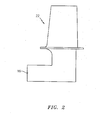
- FIG. 2 there is shown the raw form or blank 22 of the turbine blade 10 to be machined.
- the turbine blade 10 is typically a cast structure formed from a nickel-based or cobalt-based alloy.
- the areas to be machined are located in the root portion 16 of the blade 10.
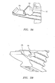
- FIG. 3A shows the tip areas 26 and 28 of the root portion 16 which are machined during the process of the present invention, while FIG. 3B shows the bottom area to be machined.
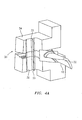
- the first jaw set 30 for clamping the root portion 16 of the blade 10 and holding the blade 10 in position during the first four cutting operations.
- the first jaw set 30 includes a first jaw member 32 and a second jaw member 34. Jaw member 32 stays fixed while jaw member 34 is able to move. The blade 10 gets placed on jaw member 32. Then jaw member 34 clamps down on the blade 10. The jaw members 32 and 34 mate with the root portion 16 of the blade 10.
- the jaw members 32 and 34 have ridges 33 and 35 respectively, which ridges are aligned with each other and with the first knife edge 52 to be formed as part of the labyrinth seal 20.
- the areas 26 and 28 to be cut are exposed to a grinding wheel 46.
- the jaw set members 32 and 34 are removably attached to a fixture 36. Any suitable means known in the art, such as removable bolts or screws, may be used to hold the jaw set members 32 and 34 to the fixture.
- a hard stop 39 at one end of the fixture 36 positions the blade 10 within the jaw members 32 and 34.
- the fixture 36 has a coolant nozzle base 40 which is attached to a source (not shown) of a coolant fluid.
- a coolant plate 42 may be attached to the base 40 using any suitable means known in the art.
- the coolant plate 42 has a plurality of coolant nozzles 44.
- the coolant nozzles 44 are oriented to aim the coolant directly at the grinding zone between the grinding wheel 46 and the blank 22. Since different cuts are being made in different areas, when a coolant plate is used, the coolant plate 42 may be replaced after particular cuts by another coolant plate 42 having coolant nozzles 44 aimed at the next site for cutting.
- the coolant may be a water soluble coolant or any other suitable coolant known in the art. If desired, the coolant plate 42 may be omitted and the nozzles 44 may be movable so that coolant is directed to the grinding zone.
- Each cut is performed by a grinding wheel 46 attached to a suitable grinding machine (not shown), such as a 4-axis Edgetek grinding machine.
- Each grinding wheel 46 may be a vitrified bond cubic boron nitride grinding wheel or any other suitable grinding wheel.
- the fixture 36 may include a dresser roll (not shown) for instances when a grinding wheel which requires dressing is used. The dresser roll is not needed if a wheel which doesn't require dressing is used, for example, a CBN plated wheel.
- the process for making the first four cuts is as follows.
- the first step is to set up the coolant nozzles 44 and the grinding wheel 46 for the first cut.
- the coolant nozzles 44 are directed at the grind zone between the grinding wheel 46 and the blade.
- the grinding wheel 46 may be dressed if necessary. In the case of a vitrified wheel, the grinding wheel may be plunged into a form dresser which generates the correct geometry.
- the first cut is made as shown in FIG. 6 .
- the grinding wheel 46 grinds the region between the root 16 and the knife edge 52 taking a number of passes at different depths of cut.
- the coolant nozzles 44 orientation plate 42 and the grinding wheel 46 are changed and the second coolant nozzle 44 configuration and the second grinding wheel 46' are set up. After the set up has been completed, the second grinding wheel 46' may be dressed if necessary. Then the second cut is made as shown in FIG. 7 . In this step, the region between the two knife edges 52 and 54 is ground taking a number of passes at different depths of cut.
- the second coolant nozzle 44 orientation is changed and a third coolant nozzle 44 configuration is used.
- the third cut is made as shown in FIG. 8 .
- the third cut grinds the top 56 of the outer knife edge 54 taking a number of passes at different depths of cut.
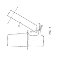
- the fourth cut is performed as shown in FIG. 9 .
- the fourth cut grinds the top 58 of the inner knife edge 52 taking a number of passes at different depths of cut.
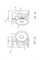
- the blade 10 is removed from the first jaw set 30 and the first jaw set 30 is replaced by the second jaw set 60 shown in FIGS. 11A-11C .
- the second jaw set 60 holds the blade 10 at an orientation which is 90 degrees offset from the orientation at which the first jaw set 30 holds the blade 10. This is so that a third grinding wheel 46" can have access to the bottom of the labyrinth seal.
- the second jaw set 60 has a first jaw member 62 and a second jaw member 64.
- the jaw members 62 and 64 grip the labyrinth seal 20 while exposing the bottom surface 59.
- the jaw members 62 and 64 have portions 66 and 68 which grip the root portion 16 of the blade.
- the third coolant nozzle 44 orientation is replaced by a fourth coolant nozzle 44 orientation.
- the grinding wheel 46' is replaced by the third grinding wheel 46". The last and final cut as shown in FIG. 10 grinds the bottom surface 59 of the labyrinth seal 20.
- a process and a system have been provided for machining blades that include labyrinth seals.
- the process may use vitrified bond grinding wheels to machine this feature of a blade.
- the process generates low cutting forces.
- two sets of jaws are used during the process to clamp on the thin labyrinth seal.
- coolant is aimed precisely within the grinding zone during each grinding step.
- the jaws in each set act as flow guides to help precisely focus the coolant into the grind zone. Any coolant that is off target will hit the jaws, which will guide the coolant back to the grind zone.
Landscapes
- Engineering & Computer Science (AREA)
- Mechanical Engineering (AREA)
- Turbine Rotor Nozzle Sealing (AREA)
- Sealing Using Fluids, Sealing Without Contact, And Removal Of Oil (AREA)
- Grinding And Polishing Of Tertiary Curved Surfaces And Surfaces With Complex Shapes (AREA)
Abstract
Description
- The present invention relates to a process for machining blade labyrinth seals used on blades. The present invention has particular utility in the manufacture of turbine blades for gas turbine engines.
- A seal design has been developed which integrates the seal into the turbine disk and mating turbine blades. This design, sometimes called a labyrinth seal, incorporates a seal located radially at the blade. The challenge is to machine the thin labyrinth form on the turbine blades, without generating any part deflection and meeting all profile and metallurgical requirements.
- There is no prior technology which has machined labyrinth features on blades used in gas turbine engines. Wire EDM (electric discharge machining) has been used to machine some blades; however, such a technique generates unacceptable metallurgy. Grinding technology does exist which machines blade root forms, but this technology has not been used to machine such a thin feature which is very susceptible to movement.
- A process for machining a labyrinth seal for a turbine blade is provided. The process broadly comprises the steps of providing a turbine blade blank having a portion to be cut to form the labyrinth seal, positioning the blank in a first set of jaws, performing a plurality of cuts to form the labyrinth seal, removing the machined blank with the labyrinth seal from the first set of jaws, placing the machined blank into a second set of jaws, and performing a final cut to grind a bottom surface of the labyrinth seal.
- A system for forming a labyrinth seal on a turbine blade is provided. The system broadly comprises a fixture having a plurality of nozzles for distributing coolant into a grinding area, a first jaw set for holding the turbine blade in a first orientation attached to the fixture, and a plurality of grinding wheels for forming the labyrinth seal.
- Other details of the blade labyrinth feature machining of the present invention, as well as other advantages attendant thereto, are set forth in the following detailed description and the accompanying drawings wherein like reference numerals depict like elements.
-
-
FIG. 1 is a side view of a turbine blade having a labyrinth seal; -
FIG. 2 is a side view of a cast turbine blade prior to machining the labyrinth seal; -
FIG. 3A illustrates the tip area of the root portion of the turbine blade to be machined; -
FIG. 3B illustrates the bottom area of the root portion of the turbine blade to be machined; -
FIGS. 4A-4C illustrate a first jaw set used to clamp and hold the turbine blade to be machined for the first four cuts; -
FIG. 5A-5B illustrate a fixture used during the machining process of the present invention; -
FIG. 6 illustrates the first cut made as part of the process of the present invention; -
FIG. 7 illustrates the second cut made as part of the process of the present invention; -
FIG. 8 illustrates the third cut made as part of the process of the present invention; -
FIG. 9 illustrates the fourth cut made as part of the process of the present invention; -
FIG. 10 illustrates a fifth cut; and -
FIG. 11A-11C illustrate a second set of jaws used to hold the blade during the fifth cut. - The process of the present invention utilizes the positive properties of a unique grinding, clamping and coolant technique to generate acceptable labyrinth seal features in a blade used in a gas turbine engine.
- Referring now to the drawings,
FIG. 1 illustrates aturbine blade 10 having aplatform 12, anairfoil portion 14, and aroot portion 16. Theturbine blade 10 also has alabyrinth seal 20 which includes a firstknife edge member 52 and a secondknife edge member 54. Theknife edge members - As will be described in more detail hereinafter, the process for machining the
knife edge members - Referring now to
FIG. 2 , there is shown the raw form or blank 22 of theturbine blade 10 to be machined. Theturbine blade 10 is typically a cast structure formed from a nickel-based or cobalt-based alloy. The areas to be machined are located in theroot portion 16 of theblade 10.FIG. 3A shows thetip areas root portion 16 which are machined during the process of the present invention, whileFIG. 3B shows the bottom area to be machined. - Referring now to
FIGS. 4A-4C , there is shown a first jaw set 30 for clamping theroot portion 16 of theblade 10 and holding theblade 10 in position during the first four cutting operations. As can be seen from this figure, thefirst jaw set 30 includes afirst jaw member 32 and asecond jaw member 34. Jawmember 32 stays fixed while jawmember 34 is able to move. Theblade 10 gets placed on jawmember 32. Thenjaw member 34 clamps down on theblade 10. Thejaw members root portion 16 of theblade 10. Thejaw members ridges first knife edge 52 to be formed as part of thelabyrinth seal 20. When positioned in the jaw set 30, theareas wheel 46. - Referring now to
FIGS. 5A and 5B , the jaw setmembers fixture 36. Any suitable means known in the art, such as removable bolts or screws, may be used to hold the jaw setmembers FIG. 5B , ahard stop 39 at one end of thefixture 36 positions theblade 10 within thejaw members - The
fixture 36 has acoolant nozzle base 40 which is attached to a source (not shown) of a coolant fluid. Acoolant plate 42 may be attached to thebase 40 using any suitable means known in the art. Thecoolant plate 42 has a plurality ofcoolant nozzles 44. Thecoolant nozzles 44 are oriented to aim the coolant directly at the grinding zone between thegrinding wheel 46 and the blank 22. Since different cuts are being made in different areas, when a coolant plate is used, thecoolant plate 42 may be replaced after particular cuts by anothercoolant plate 42 havingcoolant nozzles 44 aimed at the next site for cutting. The coolant may be a water soluble coolant or any other suitable coolant known in the art. If desired, thecoolant plate 42 may be omitted and thenozzles 44 may be movable so that coolant is directed to the grinding zone. - Each cut is performed by a grinding
wheel 46 attached to a suitable grinding machine (not shown), such as a 4-axis Edgetek grinding machine. Each grindingwheel 46 may be a vitrified bond cubic boron nitride grinding wheel or any other suitable grinding wheel. Thefixture 36 may include a dresser roll (not shown) for instances when a grinding wheel which requires dressing is used. The dresser roll is not needed if a wheel which doesn't require dressing is used, for example, a CBN plated wheel. - The process for making the first four cuts is as follows. The first step is to set up the
coolant nozzles 44 and thegrinding wheel 46 for the first cut. The coolant nozzles 44 are directed at the grind zone between thegrinding wheel 46 and the blade. After the set up has been completed, the grindingwheel 46 may be dressed if necessary. In the case of a vitrified wheel, the grinding wheel may be plunged into a form dresser which generates the correct geometry. Then the first cut is made as shown inFIG. 6 . The grindingwheel 46 grinds the region between theroot 16 and theknife edge 52 taking a number of passes at different depths of cut. - After the first cut has been completed, the
coolant nozzles 44orientation plate 42 and thegrinding wheel 46 are changed and thesecond coolant nozzle 44 configuration and thesecond grinding wheel 46' are set up. After the set up has been completed, thesecond grinding wheel 46' may be dressed if necessary. Then the second cut is made as shown inFIG. 7 . In this step, the region between the twoknife edges - After the second cut has been completed, the
second coolant nozzle 44 orientation is changed and athird coolant nozzle 44 configuration is used. The third cut is made as shown inFIG. 8 . The third cut grinds the top 56 of theouter knife edge 54 taking a number of passes at different depths of cut. After the third cut is finished, the fourth cut is performed as shown inFIG. 9 . The fourth cut grinds the top 58 of theinner knife edge 52 taking a number of passes at different depths of cut. - After the first four cuts have been completed, the
blade 10 is removed from the first jaw set 30 and the first jaw set 30 is replaced by the second jaw set 60 shown inFIGS. 11A-11C . As can be seen by comparingFIGS. 4A and11A , the second jaw set 60 holds theblade 10 at an orientation which is 90 degrees offset from the orientation at which the first jaw set 30 holds theblade 10. This is so that athird grinding wheel 46" can have access to the bottom of the labyrinth seal. - The second jaw set 60 has a
first jaw member 62 and asecond jaw member 64. Thejaw members labyrinth seal 20 while exposing thebottom surface 59. As can be seen fromFIG. 11C , thejaw members portions root portion 16 of the blade. - After the second jaw set 60 has been installed in the
fixture 36, thethird coolant nozzle 44 orientation is replaced by afourth coolant nozzle 44 orientation. Additionally, the grindingwheel 46' is replaced by thethird grinding wheel 46". The last and final cut as shown inFIG. 10 grinds thebottom surface 59 of thelabyrinth seal 20. - As can be seen from the foregoing description, a process and a system have been provided for machining blades that include labyrinth seals. The process may use vitrified bond grinding wheels to machine this feature of a blade. The process generates low cutting forces. In order to prevent part movement, two sets of jaws are used during the process to clamp on the thin labyrinth seal. To maintain low cutting forces and proper metallurgical results, coolant is aimed precisely within the grinding zone during each grinding step. The jaws in each set act as flow guides to help precisely focus the coolant into the grind zone. Any coolant that is off target will hit the jaws, which will guide the coolant back to the grind zone.
Claims (10)
- A system for forming a labyrinth seal (20) on a turbine blade (10), said system comprising:a fixture (36) having a plurality of nozzles (44) for distributing a coolant;a first jaw set (30) for holding said turbine blade (10) in a first orientation attached to said fixture (36); anda plurality of grinding wheels (46,46',46") for forming said labyrinth seal.
- The system of claim 1, wherein each of said grinding wheels (46,46',46") comprises a vitrified bond cubic boron nitride wheel.
- The system of claim 1 or 2, wherein said plurality of grinding wheels (46,46',46") comprises a first means (46) for grinding a region between a root portion (16) of the turbine blade (10) and a first knife edge (52).
- The system of claim 3, wherein said plurality of grinding wheels comprises a second means (46') for grinding a region between the first knife edge (52) and a second knife edge (54), for grinding a top portion (56) of the second knife edge (54), and for grinding a top portion (58) of the first knife edge (52).
- The system of any of any preceding claim, comprising a second jaw set (60) for holding said turbine blade (10) with said machined labyrinth seal (20) at a second orientation perpendicular to said first orientation.
- The system of claim 5, wherein said plurality of grinding wheels (46,46',46") comprises a third means (46") for grinding a bottom surface (59) of said labyrinth seal (20).
- The system of any preceding claim, wherein said plurality of grinding wheels comprises three grinding wheels (46,46',46") with the first two (46,46') of said grinding wheels being used to form the labyrinth seal (20) and the third (46") of said grinding wheels being used to grind a bottom surface (59) of said labyrinth seal (20).
- The system of any preceding claim wherein said fixture (36) has a coolant nozzle base (40) and a coolant plate (42) attached to said base (40), said coolant plate (42) having a plurality of coolant nozzles (44).
- The system of claim 8 wherein said coolant plate (42) is replacable by another coolant plate (42).
- The system of any of claims 1 to 7 wherein said coolant nozzles (44) are movable.
Applications Claiming Priority (2)
| Application Number | Priority Date | Filing Date | Title |
|---|---|---|---|
| US11/704,646 US8181346B2 (en) | 2007-02-09 | 2007-02-09 | System for forming a labyrinth seal on a turbine blade |
| EP08250487.9A EP1955812B1 (en) | 2007-02-09 | 2008-02-08 | Blade feature machining |
Related Parent Applications (2)
| Application Number | Title | Priority Date | Filing Date |
|---|---|---|---|
| EP08250487.9A Division EP1955812B1 (en) | 2007-02-09 | 2008-02-08 | Blade feature machining |
| EP08250487.9 Division | 2008-02-08 |
Publications (3)
| Publication Number | Publication Date |
|---|---|
| EP2471631A2 true EP2471631A2 (en) | 2012-07-04 |
| EP2471631A3 EP2471631A3 (en) | 2013-01-09 |
| EP2471631B1 EP2471631B1 (en) | 2016-08-24 |
Family
ID=39323053
Family Applications (2)
| Application Number | Title | Priority Date | Filing Date |
|---|---|---|---|
| EP12162545.3A Not-in-force EP2471631B1 (en) | 2007-02-09 | 2008-02-08 | A system for forming a labyrinth seal |
| EP08250487.9A Expired - Fee Related EP1955812B1 (en) | 2007-02-09 | 2008-02-08 | Blade feature machining |
Family Applications After (1)
| Application Number | Title | Priority Date | Filing Date |
|---|---|---|---|
| EP08250487.9A Expired - Fee Related EP1955812B1 (en) | 2007-02-09 | 2008-02-08 | Blade feature machining |
Country Status (2)
| Country | Link |
|---|---|
| US (1) | US8181346B2 (en) |
| EP (2) | EP2471631B1 (en) |
Cited By (2)
| Publication number | Priority date | Publication date | Assignee | Title |
|---|---|---|---|---|
| CN108005733A (en) * | 2016-10-27 | 2018-05-08 | 北京精密机电控制设备研究所 | A kind of highway turbine machine suitable for high temperature and pressure working medium |
| CN112372724A (en) * | 2020-10-19 | 2021-02-19 | 邵阳县华锐合金工具有限公司 | Blunting prevention device for tungsten steel blade |
Families Citing this family (5)
| Publication number | Priority date | Publication date | Assignee | Title |
|---|---|---|---|---|
| DE202008000645U1 (en) * | 2008-01-16 | 2008-06-26 | Höfler Maschinenbau GmbH | Device for gear grinding |
| FR2947472B1 (en) * | 2009-07-03 | 2011-11-18 | Snecma | METHOD AND DEVICE FOR MACHINING A PIECE BY ABRASION |
| US20140013599A1 (en) * | 2012-07-11 | 2014-01-16 | Pratt & Whitney | Method of Manufacturing Fan Blade Shields |
| CN111922938B (en) * | 2020-07-30 | 2022-04-01 | 中国航发沈阳发动机研究所 | Blade clamping device |
| CN117260200B (en) * | 2023-10-31 | 2026-03-24 | 中国航发动力股份有限公司 | A method for processing stator blades |
Family Cites Families (7)
| Publication number | Priority date | Publication date | Assignee | Title |
|---|---|---|---|---|
| US3986847A (en) * | 1973-06-15 | 1976-10-19 | Cincinnati Millacron, Inc. | Vitreous bonded cubic boron nitride abrasive articles |
| US4128929A (en) * | 1977-03-15 | 1978-12-12 | Demusis Ralph T | Method of restoring worn turbine components |
| US4607460A (en) * | 1985-04-18 | 1986-08-26 | Hauni-Werke Korber & Co. Kg | Grinding machine with a reciprocable column for work supporting devices |
| US4827675A (en) * | 1987-07-09 | 1989-05-09 | United Technologies Corporation | Method and apparatus for forming a curved slot |
| JPH06312358A (en) | 1993-04-26 | 1994-11-08 | Mitsubishi Heavy Ind Ltd | Automatic grinding method for turbine blade |
| DE10062922A1 (en) | 2000-12-16 | 2002-06-20 | Blohm Maschb Gmbh | Workpiece holder for a grinding machine |
| US7150101B2 (en) * | 2003-12-15 | 2006-12-19 | General Electric Company | Apparatus for fabricating components |
-
2007
- 2007-02-09 US US11/704,646 patent/US8181346B2/en not_active Expired - Fee Related
-
2008
- 2008-02-08 EP EP12162545.3A patent/EP2471631B1/en not_active Not-in-force
- 2008-02-08 EP EP08250487.9A patent/EP1955812B1/en not_active Expired - Fee Related
Non-Patent Citations (1)
| Title |
|---|
| None |
Cited By (2)
| Publication number | Priority date | Publication date | Assignee | Title |
|---|---|---|---|---|
| CN108005733A (en) * | 2016-10-27 | 2018-05-08 | 北京精密机电控制设备研究所 | A kind of highway turbine machine suitable for high temperature and pressure working medium |
| CN112372724A (en) * | 2020-10-19 | 2021-02-19 | 邵阳县华锐合金工具有限公司 | Blunting prevention device for tungsten steel blade |
Also Published As
| Publication number | Publication date |
|---|---|
| EP1955812A1 (en) | 2008-08-13 |
| EP1955812B1 (en) | 2013-07-03 |
| US8181346B2 (en) | 2012-05-22 |
| EP2471631A3 (en) | 2013-01-09 |
| EP2471631B1 (en) | 2016-08-24 |
| US20080189945A1 (en) | 2008-08-14 |
Similar Documents
| Publication | Publication Date | Title |
|---|---|---|
| EP2471631B1 (en) | A system for forming a labyrinth seal | |
| CA1130546A (en) | Apparatus and method for refinishing turbine blade airseals | |
| US6883234B2 (en) | Process for machining axial blade slots in turbine disks for jet engines | |
| CN105252224B (en) | A kind of aero-engine outer duct outlet guide vanes processing method | |
| US8286348B2 (en) | Method of manufacturing and refinishing integrally bladed rotors | |
| CN104010763B (en) | Apparatus for contouring gas turbine blades | |
| US20150013126A1 (en) | Device for recontouring a gas turbine blade | |
| CN103786003B (en) | A kind of processing method of aero-engine guide vane listrium | |
| CN111113208A (en) | A method for machining complex hollow turbine guide vanes with radial arc grooves | |
| KR20220116398A (en) | Method for manufacturing or for repairing a component of a rotary machine as well as a component manufactured or repaired using such a method | |
| US10556310B2 (en) | Method for cutting machining of turbine blades | |
| CN102950336A (en) | Special cutter and method for processing closed elongated inner cavity profile | |
| US4639991A (en) | Process for producing a new edge on an airfoil blade particularly the fan blade for a gas turbine engine | |
| CN102922397A (en) | Accessory lathe-grinding integration device for lathe machining center and use method thereof | |
| CN114131925A (en) | A method and device for spatial position forming based on additive manufacturing | |
| US20140305270A1 (en) | Shaping of aerofoil edges | |
| US20170066071A1 (en) | Device and method for producing a blade airfoil | |
| CN201455808U (en) | Automatic finisher for grinding wheel | |
| EP2943303B1 (en) | Turbine shroud milling | |
| US4550497A (en) | Tool to produce a new angle on a fan blade | |
| JPS62130298A (en) | Electrochemical processing method | |
| CN115255845B (en) | Preparation method of conductive diamond milling cutter and cutter thereof | |
| CN105345057A (en) | Center hole benchmark correcting method reducing cutting torque | |
| CN117047662B (en) | A method for roughing, array grinding, and abrasive flow polishing of integral bladed disks using water jet grinding. | |
| CN210548649U (en) | A kind of electric discharge machining device for aero-engine outer ring blade hole |
Legal Events
| Date | Code | Title | Description |
|---|---|---|---|
| AC | Divisional application: reference to earlier application |
Ref document number: 1955812 Country of ref document: EP Kind code of ref document: P |
|
| AK | Designated contracting states |
Kind code of ref document: A2 Designated state(s): AT BE BG CH CY CZ DE DK EE ES FI FR GB GR HR HU IE IS IT LI LT LU LV MC MT NL NO PL PT RO SE SI SK TR |
|
| AX | Request for extension of the european patent |
Extension state: AL BA MK RS |
|
| PUAI | Public reference made under article 153(3) epc to a published international application that has entered the european phase |
Free format text: ORIGINAL CODE: 0009012 |
|
| RIN1 | Information on inventor provided before grant (corrected) |
Inventor name: VAILLETTE, BERNARD D. Inventor name: BARNAT, KRZYSZTOF |
|
| PUAL | Search report despatched |
Free format text: ORIGINAL CODE: 0009013 |
|
| AK | Designated contracting states |
Kind code of ref document: A3 Designated state(s): AT BE BG CH CY CZ DE DK EE ES FI FR GB GR HR HU IE IS IT LI LT LU LV MC MT NL NO PL PT RO SE SI SK TR |
|
| AX | Request for extension of the european patent |
Extension state: AL BA MK RS |
|
| RIC1 | Information provided on ipc code assigned before grant |
Ipc: B24B 19/14 20060101AFI20121130BHEP Ipc: B24B 57/02 20060101ALI20121130BHEP Ipc: B24B 41/06 20120101ALI20121130BHEP |
|
| 17P | Request for examination filed |
Effective date: 20130705 |
|
| RBV | Designated contracting states (corrected) |
Designated state(s): AT BE BG CH CY CZ DE DK EE ES FI FR GB GR HR HU IE IS IT LI LT LU LV MC MT NL NO PL PT RO SE SI SK TR |
|
| 17Q | First examination report despatched |
Effective date: 20150410 |
|
| GRAP | Despatch of communication of intention to grant a patent |
Free format text: ORIGINAL CODE: EPIDOSNIGR1 |
|
| INTG | Intention to grant announced |
Effective date: 20160317 |
|
| GRAS | Grant fee paid |
Free format text: ORIGINAL CODE: EPIDOSNIGR3 |
|
| GRAA | (expected) grant |
Free format text: ORIGINAL CODE: 0009210 |
|
| AC | Divisional application: reference to earlier application |
Ref document number: 1955812 Country of ref document: EP Kind code of ref document: P |
|
| AK | Designated contracting states |
Kind code of ref document: B1 Designated state(s): AT BE BG CH CY CZ DE DK EE ES FI FR GB GR HR HU IE IS IT LI LT LU LV MC MT NL NO PL PT RO SE SI SK TR |
|
| REG | Reference to a national code |
Ref country code: GB Ref legal event code: FG4D |
|
| REG | Reference to a national code |
Ref country code: CH Ref legal event code: EP |
|
| REG | Reference to a national code |
Ref country code: AT Ref legal event code: REF Ref document number: 822621 Country of ref document: AT Kind code of ref document: T Effective date: 20160915 |
|
| REG | Reference to a national code |
Ref country code: IE Ref legal event code: FG4D |
|
| REG | Reference to a national code |
Ref country code: DE Ref legal event code: R096 Ref document number: 602008045930 Country of ref document: DE |
|
| REG | Reference to a national code |
Ref country code: CH Ref legal event code: PCOW Free format text: NEW ADDRESS: 10 FARM SPRINGS RD., FARMINGTON, CT 06032 (US) |
|
| RAP2 | Party data changed (patent owner data changed or rights of a patent transferred) |
Owner name: UNITED TECHNOLOGIES CORPORATION |
|
| REG | Reference to a national code |
Ref country code: LT Ref legal event code: MG4D |
|
| REG | Reference to a national code |
Ref country code: NL Ref legal event code: MP Effective date: 20160824 |
|
| REG | Reference to a national code |
Ref country code: AT Ref legal event code: MK05 Ref document number: 822621 Country of ref document: AT Kind code of ref document: T Effective date: 20160824 |
|
| PG25 | Lapsed in a contracting state [announced via postgrant information from national office to epo] |
Ref country code: LT Free format text: LAPSE BECAUSE OF FAILURE TO SUBMIT A TRANSLATION OF THE DESCRIPTION OR TO PAY THE FEE WITHIN THE PRESCRIBED TIME-LIMIT Effective date: 20160824 Ref country code: HR Free format text: LAPSE BECAUSE OF FAILURE TO SUBMIT A TRANSLATION OF THE DESCRIPTION OR TO PAY THE FEE WITHIN THE PRESCRIBED TIME-LIMIT Effective date: 20160824 Ref country code: FI Free format text: LAPSE BECAUSE OF FAILURE TO SUBMIT A TRANSLATION OF THE DESCRIPTION OR TO PAY THE FEE WITHIN THE PRESCRIBED TIME-LIMIT Effective date: 20160824 Ref country code: NL Free format text: LAPSE BECAUSE OF FAILURE TO SUBMIT A TRANSLATION OF THE DESCRIPTION OR TO PAY THE FEE WITHIN THE PRESCRIBED TIME-LIMIT Effective date: 20160824 Ref country code: IT Free format text: LAPSE BECAUSE OF FAILURE TO SUBMIT A TRANSLATION OF THE DESCRIPTION OR TO PAY THE FEE WITHIN THE PRESCRIBED TIME-LIMIT Effective date: 20160824 Ref country code: NO Free format text: LAPSE BECAUSE OF FAILURE TO SUBMIT A TRANSLATION OF THE DESCRIPTION OR TO PAY THE FEE WITHIN THE PRESCRIBED TIME-LIMIT Effective date: 20161124 |
|
| PG25 | Lapsed in a contracting state [announced via postgrant information from national office to epo] |
Ref country code: AT Free format text: LAPSE BECAUSE OF FAILURE TO SUBMIT A TRANSLATION OF THE DESCRIPTION OR TO PAY THE FEE WITHIN THE PRESCRIBED TIME-LIMIT Effective date: 20160824 Ref country code: PT Free format text: LAPSE BECAUSE OF FAILURE TO SUBMIT A TRANSLATION OF THE DESCRIPTION OR TO PAY THE FEE WITHIN THE PRESCRIBED TIME-LIMIT Effective date: 20161226 Ref country code: GR Free format text: LAPSE BECAUSE OF FAILURE TO SUBMIT A TRANSLATION OF THE DESCRIPTION OR TO PAY THE FEE WITHIN THE PRESCRIBED TIME-LIMIT Effective date: 20161125 Ref country code: LV Free format text: LAPSE BECAUSE OF FAILURE TO SUBMIT A TRANSLATION OF THE DESCRIPTION OR TO PAY THE FEE WITHIN THE PRESCRIBED TIME-LIMIT Effective date: 20160824 Ref country code: ES Free format text: LAPSE BECAUSE OF FAILURE TO SUBMIT A TRANSLATION OF THE DESCRIPTION OR TO PAY THE FEE WITHIN THE PRESCRIBED TIME-LIMIT Effective date: 20160824 Ref country code: SE Free format text: LAPSE BECAUSE OF FAILURE TO SUBMIT A TRANSLATION OF THE DESCRIPTION OR TO PAY THE FEE WITHIN THE PRESCRIBED TIME-LIMIT Effective date: 20160824 |
|
| PG25 | Lapsed in a contracting state [announced via postgrant information from national office to epo] |
Ref country code: RO Free format text: LAPSE BECAUSE OF FAILURE TO SUBMIT A TRANSLATION OF THE DESCRIPTION OR TO PAY THE FEE WITHIN THE PRESCRIBED TIME-LIMIT Effective date: 20160824 Ref country code: EE Free format text: LAPSE BECAUSE OF FAILURE TO SUBMIT A TRANSLATION OF THE DESCRIPTION OR TO PAY THE FEE WITHIN THE PRESCRIBED TIME-LIMIT Effective date: 20160824 |
|
| REG | Reference to a national code |
Ref country code: DE Ref legal event code: R097 Ref document number: 602008045930 Country of ref document: DE |
|
| PG25 | Lapsed in a contracting state [announced via postgrant information from national office to epo] |
Ref country code: CZ Free format text: LAPSE BECAUSE OF FAILURE TO SUBMIT A TRANSLATION OF THE DESCRIPTION OR TO PAY THE FEE WITHIN THE PRESCRIBED TIME-LIMIT Effective date: 20160824 Ref country code: BG Free format text: LAPSE BECAUSE OF FAILURE TO SUBMIT A TRANSLATION OF THE DESCRIPTION OR TO PAY THE FEE WITHIN THE PRESCRIBED TIME-LIMIT Effective date: 20161124 Ref country code: PL Free format text: LAPSE BECAUSE OF FAILURE TO SUBMIT A TRANSLATION OF THE DESCRIPTION OR TO PAY THE FEE WITHIN THE PRESCRIBED TIME-LIMIT Effective date: 20160824 Ref country code: DK Free format text: LAPSE BECAUSE OF FAILURE TO SUBMIT A TRANSLATION OF THE DESCRIPTION OR TO PAY THE FEE WITHIN THE PRESCRIBED TIME-LIMIT Effective date: 20160824 Ref country code: BE Free format text: LAPSE BECAUSE OF FAILURE TO SUBMIT A TRANSLATION OF THE DESCRIPTION OR TO PAY THE FEE WITHIN THE PRESCRIBED TIME-LIMIT Effective date: 20160824 Ref country code: SK Free format text: LAPSE BECAUSE OF FAILURE TO SUBMIT A TRANSLATION OF THE DESCRIPTION OR TO PAY THE FEE WITHIN THE PRESCRIBED TIME-LIMIT Effective date: 20160824 |
|
| PLBE | No opposition filed within time limit |
Free format text: ORIGINAL CODE: 0009261 |
|
| STAA | Information on the status of an ep patent application or granted ep patent |
Free format text: STATUS: NO OPPOSITION FILED WITHIN TIME LIMIT |
|
| REG | Reference to a national code |
Ref country code: DE Ref legal event code: R082 Ref document number: 602008045930 Country of ref document: DE Representative=s name: SCHMITT-NILSON SCHRAUD WAIBEL WOHLFROM PATENTA, DE |
|
| 26N | No opposition filed |
Effective date: 20170526 |
|
| PG25 | Lapsed in a contracting state [announced via postgrant information from national office to epo] |
Ref country code: SI Free format text: LAPSE BECAUSE OF FAILURE TO SUBMIT A TRANSLATION OF THE DESCRIPTION OR TO PAY THE FEE WITHIN THE PRESCRIBED TIME-LIMIT Effective date: 20160824 |
|
| PG25 | Lapsed in a contracting state [announced via postgrant information from national office to epo] |
Ref country code: MC Free format text: LAPSE BECAUSE OF FAILURE TO SUBMIT A TRANSLATION OF THE DESCRIPTION OR TO PAY THE FEE WITHIN THE PRESCRIBED TIME-LIMIT Effective date: 20160824 |
|
| REG | Reference to a national code |
Ref country code: CH Ref legal event code: PL |
|
| PG25 | Lapsed in a contracting state [announced via postgrant information from national office to epo] |
Ref country code: LI Free format text: LAPSE BECAUSE OF NON-PAYMENT OF DUE FEES Effective date: 20170228 Ref country code: CH Free format text: LAPSE BECAUSE OF NON-PAYMENT OF DUE FEES Effective date: 20170228 |
|
| REG | Reference to a national code |
Ref country code: IE Ref legal event code: MM4A |
|
| REG | Reference to a national code |
Ref country code: FR Ref legal event code: ST Effective date: 20171031 |
|
| PG25 | Lapsed in a contracting state [announced via postgrant information from national office to epo] |
Ref country code: LU Free format text: LAPSE BECAUSE OF NON-PAYMENT OF DUE FEES Effective date: 20170208 |
|
| PG25 | Lapsed in a contracting state [announced via postgrant information from national office to epo] |
Ref country code: FR Free format text: LAPSE BECAUSE OF NON-PAYMENT OF DUE FEES Effective date: 20170228 |
|
| PG25 | Lapsed in a contracting state [announced via postgrant information from national office to epo] |
Ref country code: IE Free format text: LAPSE BECAUSE OF NON-PAYMENT OF DUE FEES Effective date: 20170208 |
|
| PG25 | Lapsed in a contracting state [announced via postgrant information from national office to epo] |
Ref country code: MT Free format text: LAPSE BECAUSE OF NON-PAYMENT OF DUE FEES Effective date: 20170208 |
|
| PG25 | Lapsed in a contracting state [announced via postgrant information from national office to epo] |
Ref country code: HU Free format text: LAPSE BECAUSE OF FAILURE TO SUBMIT A TRANSLATION OF THE DESCRIPTION OR TO PAY THE FEE WITHIN THE PRESCRIBED TIME-LIMIT; INVALID AB INITIO Effective date: 20080208 |
|
| PG25 | Lapsed in a contracting state [announced via postgrant information from national office to epo] |
Ref country code: CY Free format text: LAPSE BECAUSE OF NON-PAYMENT OF DUE FEES Effective date: 20160824 |
|
| PG25 | Lapsed in a contracting state [announced via postgrant information from national office to epo] |
Ref country code: TR Free format text: LAPSE BECAUSE OF FAILURE TO SUBMIT A TRANSLATION OF THE DESCRIPTION OR TO PAY THE FEE WITHIN THE PRESCRIBED TIME-LIMIT Effective date: 20160824 |
|
| PG25 | Lapsed in a contracting state [announced via postgrant information from national office to epo] |
Ref country code: IS Free format text: LAPSE BECAUSE OF FAILURE TO SUBMIT A TRANSLATION OF THE DESCRIPTION OR TO PAY THE FEE WITHIN THE PRESCRIBED TIME-LIMIT Effective date: 20161224 |
|
| PGFP | Annual fee paid to national office [announced via postgrant information from national office to epo] |
Ref country code: GB Payment date: 20220124 Year of fee payment: 15 Ref country code: DE Payment date: 20220119 Year of fee payment: 15 |
|
| REG | Reference to a national code |
Ref country code: DE Ref legal event code: R081 Ref document number: 602008045930 Country of ref document: DE Owner name: RAYTHEON TECHNOLOGIES CORPORATION (N.D.GES.D.S, US Free format text: FORMER OWNER: UNITED TECHNOLOGIES CORPORATION, HARTFORD, CONN., US |
|
| REG | Reference to a national code |
Ref country code: DE Ref legal event code: R119 Ref document number: 602008045930 Country of ref document: DE |
|
| GBPC | Gb: european patent ceased through non-payment of renewal fee |
Effective date: 20230208 |
|
| PG25 | Lapsed in a contracting state [announced via postgrant information from national office to epo] |
Ref country code: GB Free format text: LAPSE BECAUSE OF NON-PAYMENT OF DUE FEES Effective date: 20230208 |
|
| PG25 | Lapsed in a contracting state [announced via postgrant information from national office to epo] |
Ref country code: GB Free format text: LAPSE BECAUSE OF NON-PAYMENT OF DUE FEES Effective date: 20230208 Ref country code: DE Free format text: LAPSE BECAUSE OF NON-PAYMENT OF DUE FEES Effective date: 20230901 |