EP2471085B1 - Electrically assisted safing of a linear actuator to provide shock tolerance - Google Patents
Electrically assisted safing of a linear actuator to provide shock tolerance Download PDFInfo
- Publication number
- EP2471085B1 EP2471085B1 EP10821212.7A EP10821212A EP2471085B1 EP 2471085 B1 EP2471085 B1 EP 2471085B1 EP 10821212 A EP10821212 A EP 10821212A EP 2471085 B1 EP2471085 B1 EP 2471085B1
- Authority
- EP
- European Patent Office
- Prior art keywords
- coil
- armature
- electrical power
- pull
- controller
- Prior art date
- Legal status (The legal status is an assumption and is not a legal conclusion. Google has not performed a legal analysis and makes no representation as to the accuracy of the status listed.)
- Active
Links
- 230000035939 shock Effects 0.000 title claims description 29
- 230000007613 environmental effect Effects 0.000 claims description 36
- 230000001052 transient effect Effects 0.000 claims description 33
- 230000007246 mechanism Effects 0.000 claims description 11
- 230000001939 inductive effect Effects 0.000 claims description 10
- 230000005672 electromagnetic field Effects 0.000 claims description 9
- 230000001965 increasing effect Effects 0.000 claims description 8
- 238000000034 method Methods 0.000 description 11
- 230000035945 sensitivity Effects 0.000 description 5
- 230000001133 acceleration Effects 0.000 description 4
- 238000010586 diagram Methods 0.000 description 4
- 235000016219 Acacia leucophloea Nutrition 0.000 description 3
- 244000131042 Acacia leucophloea Species 0.000 description 3
- 230000008859 change Effects 0.000 description 3
- 230000004044 response Effects 0.000 description 3
- CWYNVVGOOAEACU-UHFFFAOYSA-N Fe2+ Chemical compound [Fe+2] CWYNVVGOOAEACU-UHFFFAOYSA-N 0.000 description 2
- 238000013459 approach Methods 0.000 description 2
- 238000013461 design Methods 0.000 description 2
- 230000000694 effects Effects 0.000 description 2
- 230000000116 mitigating effect Effects 0.000 description 2
- 238000012545 processing Methods 0.000 description 2
- 230000009471 action Effects 0.000 description 1
- 238000007792 addition Methods 0.000 description 1
- 230000002411 adverse Effects 0.000 description 1
- 230000000703 anti-shock Effects 0.000 description 1
- 230000001419 dependent effect Effects 0.000 description 1
- 238000001514 detection method Methods 0.000 description 1
- 230000009977 dual effect Effects 0.000 description 1
- 239000012530 fluid Substances 0.000 description 1
- 238000010438 heat treatment Methods 0.000 description 1
- 230000014759 maintenance of location Effects 0.000 description 1
- 238000005259 measurement Methods 0.000 description 1
- 238000012986 modification Methods 0.000 description 1
- 230000004048 modification Effects 0.000 description 1
- 238000013021 overheating Methods 0.000 description 1
- 238000012360 testing method Methods 0.000 description 1
Images


Classifications
-
- H—ELECTRICITY
- H01—ELECTRIC ELEMENTS
- H01H—ELECTRIC SWITCHES; RELAYS; SELECTORS; EMERGENCY PROTECTIVE DEVICES
- H01H71/00—Details of the protective switches or relays covered by groups H01H73/00 - H01H83/00
- H01H71/10—Operating or release mechanisms
- H01H71/1054—Means for avoiding unauthorised release
-
- H—ELECTRICITY
- H01—ELECTRIC ELEMENTS
- H01H—ELECTRIC SWITCHES; RELAYS; SELECTORS; EMERGENCY PROTECTIVE DEVICES
- H01H47/00—Circuit arrangements not adapted to a particular application of the relay and designed to obtain desired operating characteristics or to provide energising current
- H01H47/002—Monitoring or fail-safe circuits
-
- H—ELECTRICITY
- H01—ELECTRIC ELEMENTS
- H01H—ELECTRIC SWITCHES; RELAYS; SELECTORS; EMERGENCY PROTECTIVE DEVICES
- H01H83/00—Protective switches, e.g. circuit-breaking switches, or protective relays operated by abnormal electrical conditions otherwise than solely by excess current
- H01H83/12—Protective switches, e.g. circuit-breaking switches, or protective relays operated by abnormal electrical conditions otherwise than solely by excess current operated by voltage falling below a predetermined value, e.g. for no-volt protection
-
- H—ELECTRICITY
- H01—ELECTRIC ELEMENTS
- H01H—ELECTRIC SWITCHES; RELAYS; SELECTORS; EMERGENCY PROTECTIVE DEVICES
- H01H35/00—Switches operated by change of a physical condition
- H01H35/14—Switches operated by change of acceleration, e.g. by shock or vibration, inertia switch
-
- H—ELECTRICITY
- H01—ELECTRIC ELEMENTS
- H01H—ELECTRIC SWITCHES; RELAYS; SELECTORS; EMERGENCY PROTECTIVE DEVICES
- H01H71/00—Details of the protective switches or relays covered by groups H01H73/00 - H01H83/00
- H01H71/10—Operating or release mechanisms
- H01H71/12—Automatic release mechanisms with or without manual release
- H01H71/24—Electromagnetic mechanisms
- H01H71/2463—Electromagnetic mechanisms with plunger type armatures
Definitions
- the present invention relates generally to shock tolerant linear actuators, and, more particularly, to a linear actuator that is electrically safed upon the onset of an environmental transient such as a shock event.
- the assignee of the instant patent application provides power distribution equipment meeting the military requirements of, for example, the U.S. Navy.
- the power distribution equipment includes electro-mechanical devices such as circuit breakers that must reliably operate in the face of large and unpredictable mechanical shocks and related environmental transients.
- UVR undervoltage release
- a UVR mechanically trips the circuit breaker to the open position, when an undervoltage event occurs.
- a UVR may be added to a circuit breaker for a number of reasons.
- a UVR may provide protection for an electrical system which employs dual power inputs by opening a breaker associated with a power source that is off-line to prevent power back-feeding into that source from an on-line power source.
- Another possible application of a UVR is to provide an inexpensive type of coordination of the breakers.
- a UVR in a branch breaker will open that breaker when the main breaker trips, thus assuring that when power is restored, that branch breaker will remain open until some required action is taken.
- the UVR must reliably trip the circuit breaker upon an onset of a specified low voltage condition, but must also be relied upon to avoid inadvertently tripping the circuit breaker as a result, for example, of a mechanical shock. Because a UVR must trip the breaker when there is no power in the system, the energy required to trip the breaker must be stored. This may be accomplished by storing energy in a helical coil spring, for example.
- a conventional UVR may include a linear actuator 1 employing a solenoid having a magnetically permeable armature 12, and an electromagnetic inductive coil 15.
- Coil 15 is wound about a magnetically permeable, cylindrical annular core 16 secured within frame 17.
- the interior of core 16 is sized to receive armature 12 and permit axial motion of armature 12.
- a helical coil spring 13 may be provided to bias the armature 12 in an extended position such that, in the absence of a countervailing force, the armature end 23 engages a circuit breaker trip button 27.
- armature 12 When a requisite amount of voltage (“holding voltage”) is provided to coil 15 by a power supply (not shown), the armature 12 is held in a retracted position by an electromagnetic field generated by coil 15, and armature end 23 is separated by some distance from trip button 27.
- holding voltage a requisite amount of voltage
- the electromagnetic field becomes insufficient to overcome the bias provided by spring 13, whereupon the armature 12 moves to the extended position and armature 23 engages trip button 27.
- the actuator described in general terms above, and many variants thereof, are well known in the art to be particularly sensitive to dynamic loads resulting from mechanical shock or vibration. This sensitivity results from the intersection of competing design imperatives.
- armature 12 upon occurrence of an undervoltage event, armature 12 must be driven by spring 13 a sufficient distance, and with sufficient force, to successfully actuate trip button 27.
- the power required to hold armature 12 in the retracted position must be minimized in order to avoid, for example, unnecessary heating of coil 15.
- efficient designs provide that the normal holding voltage provided to coil 15 has minimal margin over that required to overcome the bias provided by spring 13.
- U.S. patents 6,255,924 , 6,486,758 , and 7,486,164 propose various additions to the basic linear actuator, intended to decrease its sensitivity to mechanical load transients.
- resilient shock mounts are provided.
- U.S. 6,486,758 discloses an "inertial lock" that mechanically safes the linear actuator in the event of a shock event.
- U.S. 7,486,164 discloses various anti-shock devices intended to mechanically prevent movement of an armature in the face of a mechanical shock.
- US 2009/0015980 A1 discloses a circuit for for a solenoid valve for fluid that increases the retention force exerted on an armature of a solenoid valve in response to an output from a vibration sensor by increasing the average value of the current supplied to the solenoid coil 12.
- US 2002/088956 A1 discloses a controlling of an actuator for an automobile or boat engine valve using a valve flipping operation in which an over-excitation voltage is applied by raising the voltage from a smaller value to a larger value.
- EP 1 981 054 A2 discloses a pull-in coil and holding coil with the pull-in coil being solely used to have a ferrous heel attract a ferrous plunger that in turn causes a non-magnetic stem to pass through an opening of a housing, while the holding coil is solely used to hold the plunger in the plunged position.
- the present inventors have recognized that adverse effects from shock sensitivity of linear actuators such as under voltage release mechanisms may be substantially eliminated by electrically safing the actuator upon a detected onset of an environmental transient such as a shock or vibration event.
- an apparatus in an embodiment, includes a solenoid actuator having an armature and at least one electromagnetic inductive coil, each coil having an electrical power input; a motion sensor; and a controller, coupled to the motion sensor and receiving an output therefrom, that adjusts the electrical power input to said coil.
- the controller adjusts the electrical power input such that an electromagnetic field generated by the coil is sufficient to restrain the armature in a desired position during the environmental transient.
- the solenoid actuator has a first and a second electromagnetic inductive coil.
- the first electromagnetic coil may be a pull-in coil; the second electromagnetic coil may be a holding coil; and when the output of the motion sensor indicates onset of an environmental transient, the controller adjusts the electrical power input by energizing the pull-in coil.
- the motion sensor is an accelerometer, a vibration sensor, and/or a shock sensor.
- the environmental transient may be a shock, and/or a vibration.
- the controller adjusts the electrical power input by increasing the input voltage and/or input current.
- the electromagnetic field generated by the coil is sufficient to overcome a mechanical counterforce.
- the mechanical counterforce may be provided by a spring, which may be a helical coil spring.
- the armature is mechanically counter-balanced to reduce relative motion between the armature and the electromagnetic inductive coil resulting from the environmental transient.
- the controller adjusts the electrical power for a time period set to exceed a duration of the environmental event by a predetermined margin.
- the controller adjusts the electrical power with a rise time substantially similar to a rise time of the environmental transient.
- an apparatus in yet a further embodiment, includes a solenoid actuator having an armature and at least one electromagnetic inductive coil, each coil having an electrical power input; an accelerometer; and a controller, coupled to the accelerometer and receiving an output therefrom, that adjusts the electrical power input to said coil.
- the controller adjusts the electrical power input such that an electromagnetic field generated by the coil is sufficient to restrain the armature in a desired position during the environmental transient.
- the solenoid actuator is a component of an undervoltage release mechanism.
- an apparatus in a further embodiment, includes a circuit breaker and an undervoltage release mechanism operable to trip said circuit breaker upon occurrence of an undervoltage event.
- the undervoltage release mechanism includes a solenoid actuator having an armature and at least one electromagnetic inductive coil; an accelerometer; and a controller, coupled to the accelerometer and receiving an output therefrom, that adjusts an electrical power input to said coil.
- the controller adjusts the electrical power input such that an electromagnetic field generated by the coil is sufficient to restrain the armature in a desired position during the environmental transient.
- an actuator 201 may be electrically coupled to, for example, power supply 202 so as to receive an electrical power input 222 which is adjustable by a controller 203.
- Actuator 201 may be a conventional linear actuator as described above in reference to Fig. 1 , or any variant thereof, provided that the actuator has a magnetically permeable armature that translates with respect to the actuator body, and at least one electromagnetic coil operable to induce a magnetic field capable of impeding the armature movement.
- Controller 203 upon receiving an output 224 from motion sensor 204 that indicates onset of an environmental transient exceeding some predetermined threshold, may adjust electrical power input 222 such that an electromagnetic field generated by the actuator coil is sufficient to "safe" actuator 201.
- "safe" means that unwanted motion of the actuator's armature with respect to the actuator body is substantially suppressed, such that the armature is restrained in a desired position.
- the inventors have found that a signal processing time during which (1) an environmental transient may be sensed, and, (2) in reaction to which the power supply parameter may be adjusted, is short enough that unwanted motion of the armature can be substantially suppressed. More particularly, for example, an embodiment provides for a rise time in the electrical power input to the coil that is substantially similar to a rise time of the environmental transient.
- electrical power input 222 remains adjusted as long as the environmental transient exceeds a predetermined threshold.
- electrical power input 222 remains adjusted for a period exceeding a duration of the environmental transient.
- the period may be selected based on characteristics of the coil. For example, the period may be selected to ensure that an increased current to the coil does not result in overheating of the coil.
- actuator 201 may have one, two, or more electromagnetic coils.
- actuator 201 may have a single coil, in which case, electrical power input 222 to be adjusted may be input voltage, current and/or power provided to the single coil. For example, if input 222 is a current, upon receiving signal 224 indicative of an onset of an environmental transient, controller 203 may adjust input 222 by increasing the current, thereby increasing the strength of the field generated by the electromagnetic coil of actuator 201.
- actuator 201 may have a first, low power, "holding” coil, and a second, higher power, “pull-in” coil.
- the "pull-in” coil is only energized when it is desired to translate (pull-in) the armature from the extended position to the retracted position.
- electrical power input 222 may be an input voltage, current and/or power provided to the pull-in coil.
- controller 203 may adjust input 222 by energizing a pull-in coil, thereby providing a stronger magnetic field than that generated by the holding coil of actuator 201 operating alone.
- the pull-in coil is energized as long as the environmental transient exceeds a predetermined threshold.
- Motion sensor 204 may be a conventional accelerometer, vibration sensor or shock sensor. Alternatively, motion sensor 204 may be custom designed to provide predetermined response characteristics. Output signal 224 may be adopted to signify various environmental transients such as shock and/or vibration.
- actuator 201 may include a helical spring or other mechanical means providing a counterforce by which the armature is biased in, for example, the extended position.
- the magnetic field generated by the electromagnetic coil is sufficient to overcome the mechanical counterforce.
- controller 203 is shown disposed between motion sensor 204 and power supply 202. Controller 203 and power supply 202, however, may be disposed in various manners, or be integrated as a single unit.
- a controller may be embodied as a switching circuit 213, operating on inputs from a motion sensor (accelerometer 214) and a power supply 212.
- Power supply 212 may include a voltage converter for providing a low voltage to switching circuit 213.
- Onset of an acceleration may be sensed by accelerometer 214 a signal representative thereof fed to switching circuit 213.
- switching circuit 213 may adjust an electrical power input to an electromagnetic coil of an actuator (not shown).
- Switching circuit 213 may include a voltage amplifier 223, a level comparator 233, a coil switch driver 243 and a power switch 253.
- Figure 4 illustrates a breadboard apparatus embodiment 401 of a suitable switching circuit 213 together with a known accelerometer 214.
- An output signal from accelerometer 214 may be received and amplified by voltage amplifier 223.
- a resulting output signal from voltage amplifier 223 may be processed by level comparator 233 to determine whether the output signal from accelerometer 214 is indicative of an environmental transient exceeding a predetermined threshold of intensity.
- a signal from level comparator 233 may cause coil switch driver 243 to initiate control of power switch 253.
- Power switch 253 may advantageously be disposed in series with input power source 301 and actuator coil 16. As a result, operation of switching circuit 213 can control the electrical power input to actuator coil 16.
- actuator coil 16 is a pull-in coil of a linear actuator.
- accelerometer 214 may be an integrated circuit accelerometer feeding operational amplifiers to take the absolute value and sum the acceleration in all three axes.
- the foregoing embodiment was found to provide good sensitivity to the shock, precise measurement of the acceleration levels, and convenient adjustability of the predetermined threshold of intensity.
- Other methods of providing the same function may be employed.
- a simple shock-sensitive switch may cause a pull-in coil to be energized.
- an output 501 of switching circuit 213 is graphed on a common time axis with a measured shock pulse signal 502 applied to an under voltage release mechanism and to the breadboard apparatus shown in Fig. 4 .
- the measured shock pulse signal 502 resulted from striking a plate, on which both a UVR mechanism and breadboard apparatus 401 were mounted, with a hammer.
- the hammer strike provided a sufficient shock level to cause the UVR to trip when not safed by switching circuit 213.
- switching circuit 213 was enabled to provide electrically assisted safing as described above, however, a rise time in a power input to an actuator coil of the UVR was such that the coil of the UVR prevented the armature from unseating and releasing.
- the rise time of the output of switching circuit 213 is substantially similar to the rise time of the mechanical shock transient.
- a linear actuator 601 having an armature 602 is illustrated.
- the armature 602 may be linked to a mechanical counterbalance 603 to reduce relative motion between armature 602 and actuator body 604 that would otherwise result from an environmental transient.
- Such an embodiment may be implemented in combination with the electrically assisted safing techniques described hereinabove, to relax, for example, requirements imposed on the electrical power input to the actuator electromagnetic inductive coil.
- While certain embodiments described herein are advantageously directed toward implementing an improved, shock-tolerant UVR for a circuit breaker, the above described techniques discovered by the present inventors are not limited to such application.
- the techniques could be applied to a number of other devices which utilize solenoid coils controlling a shock-sensitive actuator, such as contactors, valves, electrical locking devices.
- the techniques may also be used in other equipment where a solid-state switch would be used to energize an electrical device which "resists" or braces against the effect of a shock pulse or rapid acceleration.
Landscapes
- Engineering & Computer Science (AREA)
- Computer Security & Cryptography (AREA)
- Reciprocating, Oscillating Or Vibrating Motors (AREA)
- Breakers (AREA)
- Electromagnets (AREA)
Description
- The present invention relates generally to shock tolerant linear actuators, and, more particularly, to a linear actuator that is electrically safed upon the onset of an environmental transient such as a shock event.
- The assignee of the instant patent application provides power distribution equipment meeting the military requirements of, for example, the U.S. Navy. The power distribution equipment includes electro-mechanical devices such as circuit breakers that must reliably operate in the face of large and unpredictable mechanical shocks and related environmental transients.
- Circuit breakers are frequently equipped with undervoltage release (UVR) mechanisms. A UVR mechanically trips the circuit breaker to the open position, when an undervoltage event occurs. A UVR may be added to a circuit breaker for a number of reasons. For example, a UVR may provide protection for an electrical system which employs dual power inputs by opening a breaker associated with a power source that is off-line to prevent power back-feeding into that source from an on-line power source. Another possible application of a UVR is to provide an inexpensive type of coordination of the breakers. A UVR in a branch breaker will open that breaker when the main breaker trips, thus assuring that when power is restored, that branch breaker will remain open until some required action is taken.
- The UVR must reliably trip the circuit breaker upon an onset of a specified low voltage condition, but must also be relied upon to avoid inadvertently tripping the circuit breaker as a result, for example, of a mechanical shock. Because a UVR must trip the breaker when there is no power in the system, the energy required to trip the breaker must be stored. This may be accomplished by storing energy in a helical coil spring, for example.
- A conventional UVR, illustrated in
Fig. 1 , may include alinear actuator 1 employing a solenoid having a magneticallypermeable armature 12, and an electromagneticinductive coil 15.Coil 15 is wound about a magnetically permeable, cylindricalannular core 16 secured withinframe 17. The interior ofcore 16 is sized to receivearmature 12 and permit axial motion ofarmature 12. Ahelical coil spring 13 may be provided to bias thearmature 12 in an extended position such that, in the absence of a countervailing force, thearmature end 23 engages a circuitbreaker trip button 27. - When a requisite amount of voltage ("holding voltage") is provided to coil 15 by a power supply (not shown), the
armature 12 is held in a retracted position by an electromagnetic field generated bycoil 15, andarmature end 23 is separated by some distance fromtrip button 27. When current is removed fromcoil 15, or the voltage from the power supply drops below the requisite holding voltage, the electromagnetic field becomes insufficient to overcome the bias provided byspring 13, whereupon thearmature 12 moves to the extended position andarmature 23 engagestrip button 27. - The actuator described in general terms above, and many variants thereof, are well known in the art to be particularly sensitive to dynamic loads resulting from mechanical shock or vibration. This sensitivity results from the intersection of competing design imperatives. On the one hand, upon occurrence of an undervoltage event,
armature 12 must be driven by spring 13 a sufficient distance, and with sufficient force, to successfully actuatetrip button 27. On the other hand, the power required to holdarmature 12 in the retracted position must be minimized in order to avoid, for example, unnecessary heating ofcoil 15. Thus, efficient designs provide that the normal holding voltage provided tocoil 15 has minimal margin over that required to overcome the bias provided byspring 13. This presents a problem when mechanical load transients are encountered, because a relatively small shock pulse, for example, can causearmature 12 to start to move from the retracted position. Once that occurs, energy stored inspring 13 can easily causeactuator 1 to inadvertently and inappropriately actuatetrip button 27. - The foregoing problem has been widely recognized in the art, and several methods directed toward mitigating it have been proposed.
- One approach, disclosed in
U.S. patent 6,317,308 , proposes to detect an unscheduled movement ofarmature 12, by observing a change in value of current flowing incoil 15, the change in value resulting from electromotive force caused by the movement. Upon registering the change in value, a holding current tocoil 15 is increased, with the objective of stopping or reversing the unscheduled movement, before an inappropriate actuation oftrip button 27 occurs. But, since the holding current may only be increased after some measurable unscheduled movement occurs, there is a problem to mitigate the risk that the counteracting increase in holding current will be too late or of insufficient strength. - Other techniques, exemplified by
U.S. patents 6,255,924 ,6,486,758 , and7,486,164 , for example, propose various additions to the basic linear actuator, intended to decrease its sensitivity to mechanical load transients. As proposed inU.S. 6,255,924 , for example, resilient shock mounts are provided.U.S. 6,486,758 discloses an "inertial lock" that mechanically safes the linear actuator in the event of a shock event.U.S. 7,486,164 discloses various anti-shock devices intended to mechanically prevent movement of an armature in the face of a mechanical shock. -
US 2009/0015980 A1 discloses a circuit for for a solenoid valve for fluid that increases the retention force exerted on an armature of a solenoid valve in response to an output from a vibration sensor by increasing the average value of the current supplied to thesolenoid coil 12. -
US 2002/088956 A1 discloses a controlling of an actuator for an automobile or boat engine valve using a valve flipping operation in which an over-excitation voltage is applied by raising the voltage from a smaller value to a larger value. -
EP 1 981 054 A2 - While the foregoing approaches mitigate to some extent the immediate problem of inappropriate actuation upon occurrence of an environmental transient, they increase the complexity, size and cost of the mechanism and/or may not be sufficient for severe military environments.
- Accordingly, there is a long felt need for improved, acceptably shock tolerant UVR's, and similar linear actuators, that avoid the disadvantages of the known techniques.
- The above object is achieved by the invention as defined in the independent claim. Advantageous embodiments of the present invention are the subject of dependent claims. It is noted that those embodiments explained below that do not fall under the scope of the invention as set out in the claims are not to be considered as embodiments of the invention.
- The present inventors have recognized that adverse effects from shock sensitivity of linear actuators such as under voltage release mechanisms may be substantially eliminated by electrically safing the actuator upon a detected onset of an environmental transient such as a shock or vibration event.
- In an embodiment, an apparatus includes a solenoid actuator having an armature and at least one electromagnetic inductive coil, each coil having an electrical power input; a motion sensor; and a controller, coupled to the motion sensor and receiving an output therefrom, that adjusts the electrical power input to said coil. When the output of the motion sensor indicates onset of an environmental transient exceeding a predetermined threshold of intensity, the controller adjusts the electrical power input such that an electromagnetic field generated by the coil is sufficient to restrain the armature in a desired position during the environmental transient.
- In a further embodiment, the solenoid actuator has a first and a second electromagnetic inductive coil. The first electromagnetic coil may be a pull-in coil; the second electromagnetic coil may be a holding coil; and when the output of the motion sensor indicates onset of an environmental transient, the controller adjusts the electrical power input by energizing the pull-in coil.
- In another embodiment, the motion sensor is an accelerometer, a vibration sensor, and/or a shock sensor. The environmental transient may be a shock, and/or a vibration.
- In an embodiment, the controller adjusts the electrical power input by increasing the input voltage and/or input current.
- In a further embodiment, the electromagnetic field generated by the coil is sufficient to overcome a mechanical counterforce. The mechanical counterforce may be provided by a spring, which may be a helical coil spring.
- In yet another embodiment, the armature is mechanically counter-balanced to reduce relative motion between the armature and the electromagnetic inductive coil resulting from the environmental transient.
- In an embodiment, the controller adjusts the electrical power for a time period set to exceed a duration of the environmental event by a predetermined margin.
- In a further embodiment, the controller adjusts the electrical power with a rise time substantially similar to a rise time of the environmental transient.
- In yet a further embodiment, an apparatus includes a solenoid actuator having an armature and at least one electromagnetic inductive coil, each coil having an electrical power input; an accelerometer; and a controller, coupled to the accelerometer and receiving an output therefrom, that adjusts the electrical power input to said coil. When the output of the accelerometer indicates onset of an environmental transient exceeding a predetermined threshold of intensity, the controller adjusts the electrical power input such that an electromagnetic field generated by the coil is sufficient to restrain the armature in a desired position during the environmental transient.
- In an embodiment, the solenoid actuator is a component of an undervoltage release mechanism.
- In a further embodiment, an apparatus includes a circuit breaker and an undervoltage release mechanism operable to trip said circuit breaker upon occurrence of an undervoltage event. The undervoltage release mechanism includes a solenoid actuator having an armature and at least one electromagnetic inductive coil; an accelerometer; and a controller, coupled to the accelerometer and receiving an output therefrom, that adjusts an electrical power input to said coil. When the output of the accelerometer indicates onset of an environmental transient exceeding a predetermined threshold of intensity, the controller adjusts the electrical power input such that an electromagnetic field generated by the coil is sufficient to restrain the armature in a desired position during the environmental transient.
-
-
FIG. 1 shows an exploded isometric view of a linear actuator known in the prior art; -
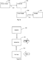
FIG. 2a shows a functional block diagram of an embodiment; -
FIG. 2b shows a functional block diagram of an embodiment; -
FIG. 3 shows an electrical block diagram of an embodiment; -
FIG. 4 shows an accelerometer and switching circuit suitable for use in an embodiment; -
FIG. 5 shows test results comparing a response time of an embodiment with a rise time of an environmental shock transient; -
FIG. 6 shows a plan view of an embodiment. - Disclosed herein is an apparatus and method whereby a solenoid actuator may be electrically safed upon detection of onset of an environmental transient. In an embodiment illustrated in
Fig. 2 , anactuator 201 may be electrically coupled to, for example,power supply 202 so as to receive anelectrical power input 222 which is adjustable by acontroller 203.Actuator 201 may be a conventional linear actuator as described above in reference toFig. 1 , or any variant thereof, provided that the actuator has a magnetically permeable armature that translates with respect to the actuator body, and at least one electromagnetic coil operable to induce a magnetic field capable of impeding the armature movement. -
Controller 203, upon receiving anoutput 224 frommotion sensor 204 that indicates onset of an environmental transient exceeding some predetermined threshold, may adjustelectrical power input 222 such that an electromagnetic field generated by the actuator coil is sufficient to "safe"actuator 201. As the term is used herein, "safe" means that unwanted motion of the actuator's armature with respect to the actuator body is substantially suppressed, such that the armature is restrained in a desired position. As discussed in more detail hereinbelow, the inventors have found that a signal processing time during which (1) an environmental transient may be sensed, and, (2) in reaction to which the power supply parameter may be adjusted, is short enough that unwanted motion of the armature can be substantially suppressed. More particularly, for example, an embodiment provides for a rise time in the electrical power input to the coil that is substantially similar to a rise time of the environmental transient. - Advantageously,
electrical power input 222 remains adjusted as long as the environmental transient exceeds a predetermined threshold. In an embodiment,electrical power input 222 remains adjusted for a period exceeding a duration of the environmental transient. Advantageously, the period may be selected based on characteristics of the coil. For example, the period may be selected to ensure that an increased current to the coil does not result in overheating of the coil. - As known in the art,
actuator 201 may have one, two, or more electromagnetic coils. In an embodiment,actuator 201 may have a single coil, in which case,electrical power input 222 to be adjusted may be input voltage, current and/or power provided to the single coil. For example, ifinput 222 is a current, upon receivingsignal 224 indicative of an onset of an environmental transient,controller 203 may adjustinput 222 by increasing the current, thereby increasing the strength of the field generated by the electromagnetic coil ofactuator 201. - In a further embodiment,
actuator 201 may have a first, low power, "holding" coil, and a second, higher power, "pull-in" coil. Conventionally, the "pull-in" coil is only energized when it is desired to translate (pull-in) the armature from the extended position to the retracted position. In such case,electrical power input 222 may be an input voltage, current and/or power provided to the pull-in coil. For example, ifinput 222 is a current, upon receivingsignal 224 indicative of an onset of an environmental transient,controller 203 may adjustinput 222 by energizing a pull-in coil, thereby providing a stronger magnetic field than that generated by the holding coil ofactuator 201 operating alone. Advantageously, the pull-in coil is energized as long as the environmental transient exceeds a predetermined threshold. -
Motion sensor 204 may be a conventional accelerometer, vibration sensor or shock sensor. Alternatively,motion sensor 204 may be custom designed to provide predetermined response characteristics.Output signal 224 may be adopted to signify various environmental transients such as shock and/or vibration. - As discussed hereinabove,
actuator 201 may include a helical spring or other mechanical means providing a counterforce by which the armature is biased in, for example, the extended position. In such case, advantageously, the magnetic field generated by the electromagnetic coil is sufficient to overcome the mechanical counterforce. - It will be understood that the embodiment illustrated in
Fig. 2a is merely an exemplary technique for providing a controller coupled to a motion sensor and controlling an electrical power input to an actuator coil. In this embodiment,controller 203 is shown disposed betweenmotion sensor 204 andpower supply 202.Controller 203 andpower supply 202, however, may be disposed in various manners, or be integrated as a single unit. - For example, as illustrated in
Fig. 2b , a controller may be embodied as aswitching circuit 213, operating on inputs from a motion sensor (accelerometer 214) and apower supply 212.Power supply 212 may include a voltage converter for providing a low voltage to switchingcircuit 213. Onset of an acceleration may be sensed by accelerometer 214 a signal representative thereof fed to switchingcircuit 213. When the signal exceeds a predetermined threshold, switchingcircuit 213 may adjust an electrical power input to an electromagnetic coil of an actuator (not shown). - Referring now to
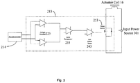
Fig. 3 , an electrical block diagram of an embodiment will be described in additional detail.Switching circuit 213 may include a voltage amplifier 223, alevel comparator 233, acoil switch driver 243 and apower switch 253.Figure 4 illustrates abreadboard apparatus embodiment 401 of asuitable switching circuit 213 together with a knownaccelerometer 214. - An output signal from
accelerometer 214 may be received and amplified by voltage amplifier 223. A resulting output signal from voltage amplifier 223 may be processed bylevel comparator 233 to determine whether the output signal fromaccelerometer 214 is indicative of an environmental transient exceeding a predetermined threshold of intensity. When a determination is made bylevel comparator 233 that the output signal fromaccelerometer 214 is indicative of an environmental transient exceeding the predetermined threshold of intensity, a signal fromlevel comparator 233 may causecoil switch driver 243 to initiate control ofpower switch 253. -
Power switch 253 may advantageously be disposed in series withinput power source 301 andactuator coil 16. As a result, operation of switchingcircuit 213 can control the electrical power input toactuator coil 16. In an embodiment,actuator coil 16 is a pull-in coil of a linear actuator. - In an embodiment,
accelerometer 214 may be an integrated circuit accelerometer feeding operational amplifiers to take the absolute value and sum the acceleration in all three axes. The foregoing embodiment was found to provide good sensitivity to the shock, precise measurement of the acceleration levels, and convenient adjustability of the predetermined threshold of intensity. Other methods of providing the same function, however, may be employed. For example, a simple shock-sensitive switch may cause a pull-in coil to be energized. - The present inventors have found that an embodiment built according to the foregoing description compares favorably in terms of envelope, mass and cost to previously known techniques for mitigating the shock sensitivity of a linear actuator.
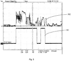
- As noted hereinabove, the present inventors have found that a signal processing time during which (1) an environmental transient may be sensed by, for example,
accelerometer 214, and, (2) in reaction to which an electrical power input to an actuator coil may be adjusted by, for example, switchingcircuit 213, is short enough that unwanted motion of the armature can be substantially suppressed. Referring now toFig. 5 , anoutput 501 of switchingcircuit 213 is graphed on a common time axis with a measuredshock pulse signal 502 applied to an under voltage release mechanism and to the breadboard apparatus shown inFig. 4 . The measuredshock pulse signal 502 resulted from striking a plate, on which both a UVR mechanism andbreadboard apparatus 401 were mounted, with a hammer. The hammer strike provided a sufficient shock level to cause the UVR to trip when not safed by switchingcircuit 213. When switchingcircuit 213 was enabled to provide electrically assisted safing as described above, however, a rise time in a power input to an actuator coil of the UVR was such that the coil of the UVR prevented the armature from unseating and releasing. As illustrated inFig. 5 , moreover, the rise time of the output of switchingcircuit 213 is substantially similar to the rise time of the mechanical shock transient. - Referring now to
Fig. 6 , alinear actuator 601, having anarmature 602, is illustrated. In the illustrated embodiment, thearmature 602 may be linked to amechanical counterbalance 603 to reduce relative motion betweenarmature 602 andactuator body 604 that would otherwise result from an environmental transient. Such an embodiment may be implemented in combination with the electrically assisted safing techniques described hereinabove, to relax, for example, requirements imposed on the electrical power input to the actuator electromagnetic inductive coil. - While certain embodiments described herein are advantageously directed toward implementing an improved, shock-tolerant UVR for a circuit breaker, the above described techniques discovered by the present inventors are not limited to such application. For example, the techniques could be applied to a number of other devices which utilize solenoid coils controlling a shock-sensitive actuator, such as contactors, valves, electrical locking devices. The techniques may also be used in other equipment where a solid-state switch would be used to energize an electrical device which "resists" or braces against the effect of a shock pulse or rapid acceleration.
- While certain preferred embodiments have been disclosed, this should not be taken as a limitation to all of the provided details. Modifications and variations of the described embodiments may be made without departing from the scope of the invention, and other embodiments should be understood to be encompassed in the present disclosure as would be understood by those of ordinary skill in the art.
Claims (12)
- An apparatus comprising:a solenoid actuator (201) comprising an armature (602), an electromagnetic inductive pull-in coil (16), and an electromagnetic inductive holding coil, each said coil adapted to receive electrical power;a motion sensor (204); anda controller (203), operatively coupled with said motion sensor (204) and configured to receive an output therefrom adapted to adjust the electrical power input to said pull-in coil, whereinwhen said output from the motion sensor (204) indicates an onset of an environmental transient exceeding a predetermined threshold of intensity, the controller (203) is adapted to adjust the electrical power input to said pull-in coil by energizing the pull-in coil such that an electromagnetic field generated by the pull-in coil and holding coil is sufficient to restrain the armature in a desired position during the environmental transient.
- The apparatus of claim 1, wherein the motion sensor (204) is at least one of an accelerometer, a vibration sensor, or a shock sensor.
- The apparatus of claim 1, wherein the environmental transient is at least one of a shock or a vibration.
- The apparatus of claim 1, wherein the controller (203) is adapted to adjust the electrical power input by increasing at least one of voltage or current to the pull-in coil.
- The apparatus of claim 1, wherein the electromagnetic fields generated by the coils are sufficient to overcome a mechanical counterforce.
- The apparatus of claim 5, wherein the mechanical counterforce is provided by a spring.
- The apparatus of claim 6, wherein the spring is a helical coil spring.
- The apparatus of claim 1, wherein the armature is mechanically counterbalanced to reduce relative motion between the armature and the electromagnetic inductive coil resulting from the environmental transient.
- The apparatus of claim 1, wherein the controller (203) is adapted to adjust the electrical power for a time period set to exceed a duration of the environmental event by a predetermined margin.
- The apparatus of claim 1, wherein the controller (203) is adapted to adjust the electrical power with a rise time substantially similar to a rise time of the environmental transient.
- The apparatus of claim 1, wherein the solenoid actuator (201) is a component of an undervoltage release mechanism.
- A circuit breaker comprising an undervoltage release mechanism operable to trip said circuit breaker upon occurrence of an undervoltage event, comprising an apparatus of claim 2, said mechanism comprising the solenoid actuator and an accelerometer.
Applications Claiming Priority (2)
| Application Number | Priority Date | Filing Date | Title |
|---|---|---|---|
| US12/572,209 US8264810B2 (en) | 2009-10-01 | 2009-10-01 | Electrically assisted safing of a linear actuator to provide shock tolerance |
| PCT/US2010/050817 WO2011041482A1 (en) | 2009-10-01 | 2010-09-30 | Electrically assisted safing of a linear actuator to provide shock tolerance |
Publications (3)
| Publication Number | Publication Date |
|---|---|
| EP2471085A1 EP2471085A1 (en) | 2012-07-04 |
| EP2471085A4 EP2471085A4 (en) | 2015-03-11 |
| EP2471085B1 true EP2471085B1 (en) | 2017-01-04 |
Family
ID=43823013
Family Applications (1)
| Application Number | Title | Priority Date | Filing Date |
|---|---|---|---|
| EP10821212.7A Active EP2471085B1 (en) | 2009-10-01 | 2010-09-30 | Electrically assisted safing of a linear actuator to provide shock tolerance |
Country Status (4)
| Country | Link |
|---|---|
| US (1) | US8264810B2 (en) |
| EP (1) | EP2471085B1 (en) |
| JP (1) | JP5727489B2 (en) |
| WO (1) | WO2011041482A1 (en) |
Families Citing this family (7)
| Publication number | Priority date | Publication date | Assignee | Title |
|---|---|---|---|---|
| EP2579291B1 (en) * | 2011-10-06 | 2014-06-04 | ABB Technology AG | Coil actuator for a switching device and related switching device |
| ES2531183T3 (en) | 2011-10-06 | 2015-03-11 | Abb Technology Ag | Switch and associated switch |
| MX389241B (en) | 2012-07-13 | 2025-03-20 | Schlage Lock Co Llc | ELECTRONIC DOOR LOCK ASSEMBLY PRELOAD COMPENSATION SYSTEM. |
| WO2015195754A1 (en) * | 2014-06-20 | 2015-12-23 | Halliburton Energy Services, Inc. | Laser-leached polycrystalline diamond and laser-leaching methods and devices |
| US10704293B2 (en) | 2015-12-01 | 2020-07-07 | Spectrum Brands, Inc. | Electronic lock with misalignment scoring system |
| DE102017102637A1 (en) * | 2017-02-10 | 2018-08-16 | Pilz Gmbh & Co. Kg | Circuit arrangement for operating at least one relay |
| US11248717B2 (en) | 2019-06-28 | 2022-02-15 | Automatic Switch Company | Modular smart solenoid valve |
Family Cites Families (28)
| Publication number | Priority date | Publication date | Assignee | Title |
|---|---|---|---|---|
| US3740738A (en) * | 1971-04-26 | 1973-06-19 | Westinghouse Electric Corp | Undervoltage trip circuit for circuit breaker |
| JPS6046506B2 (en) * | 1979-06-07 | 1985-10-16 | 三菱電機株式会社 | Shiya disconnector |
| US4370635A (en) * | 1980-09-29 | 1983-01-25 | Siemens-Allis, Inc. | Undervoltage release device for a circuit breaker |
| US4659969A (en) * | 1984-08-09 | 1987-04-21 | Synektron Corporation | Variable reluctance actuator having position sensing and control |
| US4631624A (en) * | 1984-11-02 | 1986-12-23 | Square D Company | Time delay undervoltage release |
| US4710739A (en) * | 1986-07-15 | 1987-12-01 | Westinghouse Electric Corp. | Circuit breaker having shock-proof trip-actuating assembly |
| US4845464A (en) * | 1988-08-09 | 1989-07-04 | Clifford Electronics, Inc. | Programmable sensor apparatus |
| JPH05106677A (en) * | 1991-10-17 | 1993-04-27 | Tokico Ltd | Damping force adjustable hydraulic shock absorber |
| FR2695478B1 (en) * | 1992-09-08 | 1994-11-18 | Aerospatiale | Shock detector and distress beacon for aircraft, comprising such a detector. |
| US5539605A (en) | 1994-05-25 | 1996-07-23 | General Electric Company | Digital circuit interrupter undervoltage release accessory |
| DE19623698A1 (en) * | 1996-06-14 | 1997-12-18 | Fev Motorentech Gmbh & Co Kg | Control of piston IC engine valve actuator |
| DE29703585U1 (en) * | 1997-02-28 | 1998-06-25 | Fev Motorentech Gmbh & Co Kg | Electromagnetic actuator with magnetic impact damping |
| US6138516A (en) * | 1997-12-17 | 2000-10-31 | Weld Star Technology, Inc. | Low-power shock detector and detection method |
| JP3928148B2 (en) * | 1998-09-29 | 2007-06-13 | 株式会社日立製作所 | Suspension control device |
| FR2786915B1 (en) * | 1998-12-07 | 2001-01-12 | Schneider Electric Ind Sa | DEVICE FOR CONTROLLING AN ELECTROMAGNET, WITH DETECTION OF AN UNSUITABLE MOVEMENT OF THE MOBILE CORE OF THE ELECTROMAGNET |
| EP1154538A1 (en) | 2000-05-10 | 2001-11-14 | Siemens Aktiengesellschaft | Under- and/or overvoltage release device |
| US6388859B1 (en) * | 2000-05-10 | 2002-05-14 | Eaton Corporation | Shock resistant breaker shunt trip |
| US6255924B1 (en) * | 2000-06-06 | 2001-07-03 | Eaton Corporation | Shock resistant circuit breaker UVR |
| US6486758B1 (en) * | 2000-11-21 | 2002-11-26 | Eaton Corporation | Shock-resistant circuit breaker with inertia lock |
| JP4642244B2 (en) * | 2001-01-09 | 2011-03-02 | 本田技研工業株式会社 | Electromagnetic actuator controller |
| JP3820960B2 (en) * | 2001-10-26 | 2006-09-13 | トヨタ自動車株式会社 | Energization control method with step-out detection of electromagnetically driven valve |
| DE10212092A1 (en) * | 2002-03-19 | 2003-10-09 | Dbt Autom Gmbh | Method and device for operating an electromagnet on an intrinsically safe DC circuit |
| DE10347877B4 (en) * | 2003-10-10 | 2008-11-27 | Bucyrus Dbt Europe Gmbh | Mining electromagnet |
| US7369021B2 (en) * | 2004-10-01 | 2008-05-06 | Eaton Corporation | Undervoltage release and circuit breaker incorporating same |
| US7064634B1 (en) * | 2005-06-22 | 2006-06-20 | Eaton Corporation | Shock resistant actuators for a circuit breaker |
| US7486164B2 (en) * | 2005-10-06 | 2009-02-03 | Eaton Corporation | Shock-resistant under-voltage release |
| US7557681B2 (en) | 2007-04-09 | 2009-07-07 | Eaton Corporation | Electrical switching apparatus accessory sub-assembly employing reversible coil frame, and accessory and electrical switching apparatus employing the same |
| JP4431996B2 (en) * | 2007-07-09 | 2010-03-17 | Smc株式会社 | Solenoid valve drive circuit and solenoid valve |
-
2009
- 2009-10-01 US US12/572,209 patent/US8264810B2/en active Active
-
2010
- 2010-09-30 EP EP10821212.7A patent/EP2471085B1/en active Active
- 2010-09-30 WO PCT/US2010/050817 patent/WO2011041482A1/en active Application Filing
- 2010-09-30 JP JP2012532297A patent/JP5727489B2/en active Active
Non-Patent Citations (1)
| Title |
|---|
| None * |
Also Published As
| Publication number | Publication date |
|---|---|
| WO2011041482A1 (en) | 2011-04-07 |
| EP2471085A1 (en) | 2012-07-04 |
| JP5727489B2 (en) | 2015-06-03 |
| JP2013507006A (en) | 2013-02-28 |
| US8264810B2 (en) | 2012-09-11 |
| EP2471085A4 (en) | 2015-03-11 |
| US20110080685A1 (en) | 2011-04-07 |
Similar Documents
| Publication | Publication Date | Title |
|---|---|---|
| EP2471085B1 (en) | Electrically assisted safing of a linear actuator to provide shock tolerance | |
| JP5188812B2 (en) | Method and apparatus for operating switchgear safely | |
| US5754387A (en) | Method of monitoring contactor operation | |
| CA2271327C (en) | Actuator assembly with calibration means and electrical power switch apparatus incorporating the actuator assembly with calibration means | |
| CA3031711A1 (en) | Method for monitoring an electromagnetically actuable brake, and vehicle having an electromagnetically actuable brake | |
| EP4343807A1 (en) | Contactor with integrated pyrotechnic interrupter | |
| EP3125258B1 (en) | Monitoring solenoid plunger position | |
| KR100932714B1 (en) | Actuating device for electric automatic fire extinguishing device | |
| CN109791828B (en) | Electromagnetic actuating system and method for operating same | |
| CA2963888C (en) | Actuators for hazard detection and suppression systems | |
| EP2166554B1 (en) | Circuit interrupter trip apparatus and method | |
| US5089931A (en) | Safety device for electrical apparatus containing a dielectric gas, in particular circuit breakers or voltage-droppers for measurement purposes | |
| KR101461367B1 (en) | Pressure switching device with a magnet-switch and a device for diagnosing the magnet-switch | |
| DK179123B1 (en) | Valve attachment, valve and method for controlling a valve | |
| EP3892580B1 (en) | Electronic safety actuator for an elevator safety brake and method of detecting position of an electronic safety actuator | |
| EP2481068B1 (en) | Trip unit | |
| JP2010140719A (en) | Circuit breaker | |
| EP3690918B1 (en) | Method and device to inhibit manual re-closing of the contacts of a protective switching device | |
| EP2652756B1 (en) | Electromagnetic actuator with under voltage release | |
| GB2381052A (en) | Evaluating coil current in an electromagnetically releasable brake | |
| JPH0777535A (en) | Acceleration sensor and air bag actuator equipped therewith |
Legal Events
| Date | Code | Title | Description |
|---|---|---|---|
| PUAI | Public reference made under article 153(3) epc to a published international application that has entered the european phase |
Free format text: ORIGINAL CODE: 0009012 |
|
| 17P | Request for examination filed |
Effective date: 20120330 |
|
| AK | Designated contracting states |
Kind code of ref document: A1 Designated state(s): AL AT BE BG CH CY CZ DE DK EE ES FI FR GB GR HR HU IE IS IT LI LT LU LV MC MK MT NL NO PL PT RO SE SI SK SM TR |
|
| DAX | Request for extension of the european patent (deleted) | ||
| REG | Reference to a national code |
Ref country code: DE Ref legal event code: R079 Ref document number: 602010039398 Country of ref document: DE Free format text: PREVIOUS MAIN CLASS: H01H0083120000 Ipc: H01H0047000000 |
|
| A4 | Supplementary search report drawn up and despatched |
Effective date: 20150209 |
|
| RIC1 | Information provided on ipc code assigned before grant |
Ipc: H01H 47/00 20060101AFI20150203BHEP Ipc: F16K 31/06 20060101ALN20150203BHEP Ipc: H01H 71/10 20060101ALI20150203BHEP |
|
| 17Q | First examination report despatched |
Effective date: 20151221 |
|
| GRAP | Despatch of communication of intention to grant a patent |
Free format text: ORIGINAL CODE: EPIDOSNIGR1 |
|
| INTG | Intention to grant announced |
Effective date: 20160713 |
|
| GRAS | Grant fee paid |
Free format text: ORIGINAL CODE: EPIDOSNIGR3 |
|
| GRAA | (expected) grant |
Free format text: ORIGINAL CODE: 0009210 |
|
| AK | Designated contracting states |
Kind code of ref document: B1 Designated state(s): AL AT BE BG CH CY CZ DE DK EE ES FI FR GB GR HR HU IE IS IT LI LT LU LV MC MK MT NL NO PL PT RO SE SI SK SM TR |
|
| REG | Reference to a national code |
Ref country code: GB Ref legal event code: FG4D |
|
| REG | Reference to a national code |
Ref country code: CH Ref legal event code: EP |
|
| REG | Reference to a national code |
Ref country code: AT Ref legal event code: REF Ref document number: 859975 Country of ref document: AT Kind code of ref document: T Effective date: 20170115 |
|
| REG | Reference to a national code |
Ref country code: IE Ref legal event code: FG4D |
|
| REG | Reference to a national code |
Ref country code: DE Ref legal event code: R096 Ref document number: 602010039398 Country of ref document: DE |
|
| REG | Reference to a national code |
Ref country code: LT Ref legal event code: MG4D Ref country code: NL Ref legal event code: MP Effective date: 20170104 |
|
| REG | Reference to a national code |
Ref country code: AT Ref legal event code: MK05 Ref document number: 859975 Country of ref document: AT Kind code of ref document: T Effective date: 20170104 |
|
| PG25 | Lapsed in a contracting state [announced via postgrant information from national office to epo] |
Ref country code: NL Free format text: LAPSE BECAUSE OF FAILURE TO SUBMIT A TRANSLATION OF THE DESCRIPTION OR TO PAY THE FEE WITHIN THE PRESCRIBED TIME-LIMIT Effective date: 20170104 |
|
| PG25 | Lapsed in a contracting state [announced via postgrant information from national office to epo] |
Ref country code: IS Free format text: LAPSE BECAUSE OF FAILURE TO SUBMIT A TRANSLATION OF THE DESCRIPTION OR TO PAY THE FEE WITHIN THE PRESCRIBED TIME-LIMIT Effective date: 20170504 Ref country code: LT Free format text: LAPSE BECAUSE OF FAILURE TO SUBMIT A TRANSLATION OF THE DESCRIPTION OR TO PAY THE FEE WITHIN THE PRESCRIBED TIME-LIMIT Effective date: 20170104 Ref country code: HR Free format text: LAPSE BECAUSE OF FAILURE TO SUBMIT A TRANSLATION OF THE DESCRIPTION OR TO PAY THE FEE WITHIN THE PRESCRIBED TIME-LIMIT Effective date: 20170104 Ref country code: GR Free format text: LAPSE BECAUSE OF FAILURE TO SUBMIT A TRANSLATION OF THE DESCRIPTION OR TO PAY THE FEE WITHIN THE PRESCRIBED TIME-LIMIT Effective date: 20170405 Ref country code: FI Free format text: LAPSE BECAUSE OF FAILURE TO SUBMIT A TRANSLATION OF THE DESCRIPTION OR TO PAY THE FEE WITHIN THE PRESCRIBED TIME-LIMIT Effective date: 20170104 Ref country code: NO Free format text: LAPSE BECAUSE OF FAILURE TO SUBMIT A TRANSLATION OF THE DESCRIPTION OR TO PAY THE FEE WITHIN THE PRESCRIBED TIME-LIMIT Effective date: 20170404 |
|
| PG25 | Lapsed in a contracting state [announced via postgrant information from national office to epo] |
Ref country code: LV Free format text: LAPSE BECAUSE OF FAILURE TO SUBMIT A TRANSLATION OF THE DESCRIPTION OR TO PAY THE FEE WITHIN THE PRESCRIBED TIME-LIMIT Effective date: 20170104 Ref country code: AT Free format text: LAPSE BECAUSE OF FAILURE TO SUBMIT A TRANSLATION OF THE DESCRIPTION OR TO PAY THE FEE WITHIN THE PRESCRIBED TIME-LIMIT Effective date: 20170104 Ref country code: PL Free format text: LAPSE BECAUSE OF FAILURE TO SUBMIT A TRANSLATION OF THE DESCRIPTION OR TO PAY THE FEE WITHIN THE PRESCRIBED TIME-LIMIT Effective date: 20170104 Ref country code: ES Free format text: LAPSE BECAUSE OF FAILURE TO SUBMIT A TRANSLATION OF THE DESCRIPTION OR TO PAY THE FEE WITHIN THE PRESCRIBED TIME-LIMIT Effective date: 20170104 Ref country code: BG Free format text: LAPSE BECAUSE OF FAILURE TO SUBMIT A TRANSLATION OF THE DESCRIPTION OR TO PAY THE FEE WITHIN THE PRESCRIBED TIME-LIMIT Effective date: 20170404 Ref country code: SE Free format text: LAPSE BECAUSE OF FAILURE TO SUBMIT A TRANSLATION OF THE DESCRIPTION OR TO PAY THE FEE WITHIN THE PRESCRIBED TIME-LIMIT Effective date: 20170104 Ref country code: PT Free format text: LAPSE BECAUSE OF FAILURE TO SUBMIT A TRANSLATION OF THE DESCRIPTION OR TO PAY THE FEE WITHIN THE PRESCRIBED TIME-LIMIT Effective date: 20170504 |
|
| REG | Reference to a national code |
Ref country code: DE Ref legal event code: R097 Ref document number: 602010039398 Country of ref document: DE |
|
| PG25 | Lapsed in a contracting state [announced via postgrant information from national office to epo] |
Ref country code: EE Free format text: LAPSE BECAUSE OF FAILURE TO SUBMIT A TRANSLATION OF THE DESCRIPTION OR TO PAY THE FEE WITHIN THE PRESCRIBED TIME-LIMIT Effective date: 20170104 Ref country code: RO Free format text: LAPSE BECAUSE OF FAILURE TO SUBMIT A TRANSLATION OF THE DESCRIPTION OR TO PAY THE FEE WITHIN THE PRESCRIBED TIME-LIMIT Effective date: 20170104 Ref country code: CZ Free format text: LAPSE BECAUSE OF FAILURE TO SUBMIT A TRANSLATION OF THE DESCRIPTION OR TO PAY THE FEE WITHIN THE PRESCRIBED TIME-LIMIT Effective date: 20170104 Ref country code: SK Free format text: LAPSE BECAUSE OF FAILURE TO SUBMIT A TRANSLATION OF THE DESCRIPTION OR TO PAY THE FEE WITHIN THE PRESCRIBED TIME-LIMIT Effective date: 20170104 |
|
| PLBE | No opposition filed within time limit |
Free format text: ORIGINAL CODE: 0009261 |
|
| STAA | Information on the status of an ep patent application or granted ep patent |
Free format text: STATUS: NO OPPOSITION FILED WITHIN TIME LIMIT |
|
| PG25 | Lapsed in a contracting state [announced via postgrant information from national office to epo] |
Ref country code: DK Free format text: LAPSE BECAUSE OF FAILURE TO SUBMIT A TRANSLATION OF THE DESCRIPTION OR TO PAY THE FEE WITHIN THE PRESCRIBED TIME-LIMIT Effective date: 20170104 Ref country code: SM Free format text: LAPSE BECAUSE OF FAILURE TO SUBMIT A TRANSLATION OF THE DESCRIPTION OR TO PAY THE FEE WITHIN THE PRESCRIBED TIME-LIMIT Effective date: 20170104 |
|
| 26N | No opposition filed |
Effective date: 20171005 |
|
| PG25 | Lapsed in a contracting state [announced via postgrant information from national office to epo] |
Ref country code: SI Free format text: LAPSE BECAUSE OF FAILURE TO SUBMIT A TRANSLATION OF THE DESCRIPTION OR TO PAY THE FEE WITHIN THE PRESCRIBED TIME-LIMIT Effective date: 20170104 |
|
| REG | Reference to a national code |
Ref country code: CH Ref legal event code: PL |
|
| PG25 | Lapsed in a contracting state [announced via postgrant information from national office to epo] |
Ref country code: MC Free format text: LAPSE BECAUSE OF FAILURE TO SUBMIT A TRANSLATION OF THE DESCRIPTION OR TO PAY THE FEE WITHIN THE PRESCRIBED TIME-LIMIT Effective date: 20170104 |
|
| REG | Reference to a national code |
Ref country code: IE Ref legal event code: MM4A |
|
| REG | Reference to a national code |
Ref country code: BE Ref legal event code: MM Effective date: 20170930 |
|
| PG25 | Lapsed in a contracting state [announced via postgrant information from national office to epo] |
Ref country code: LU Free format text: LAPSE BECAUSE OF NON-PAYMENT OF DUE FEES Effective date: 20170930 |
|
| REG | Reference to a national code |
Ref country code: FR Ref legal event code: ST Effective date: 20180531 |
|
| PG25 | Lapsed in a contracting state [announced via postgrant information from national office to epo] |
Ref country code: IE Free format text: LAPSE BECAUSE OF NON-PAYMENT OF DUE FEES Effective date: 20170930 Ref country code: CH Free format text: LAPSE BECAUSE OF NON-PAYMENT OF DUE FEES Effective date: 20170930 Ref country code: LI Free format text: LAPSE BECAUSE OF NON-PAYMENT OF DUE FEES Effective date: 20170930 |
|
| PG25 | Lapsed in a contracting state [announced via postgrant information from national office to epo] |
Ref country code: BE Free format text: LAPSE BECAUSE OF NON-PAYMENT OF DUE FEES Effective date: 20170930 Ref country code: FR Free format text: LAPSE BECAUSE OF NON-PAYMENT OF DUE FEES Effective date: 20171002 |
|
| PG25 | Lapsed in a contracting state [announced via postgrant information from national office to epo] |
Ref country code: MT Free format text: LAPSE BECAUSE OF NON-PAYMENT OF DUE FEES Effective date: 20170930 |
|
| PG25 | Lapsed in a contracting state [announced via postgrant information from national office to epo] |
Ref country code: HU Free format text: LAPSE BECAUSE OF FAILURE TO SUBMIT A TRANSLATION OF THE DESCRIPTION OR TO PAY THE FEE WITHIN THE PRESCRIBED TIME-LIMIT; INVALID AB INITIO Effective date: 20100930 |
|
| PG25 | Lapsed in a contracting state [announced via postgrant information from national office to epo] |
Ref country code: CY Free format text: LAPSE BECAUSE OF NON-PAYMENT OF DUE FEES Effective date: 20170104 |
|
| PG25 | Lapsed in a contracting state [announced via postgrant information from national office to epo] |
Ref country code: MK Free format text: LAPSE BECAUSE OF FAILURE TO SUBMIT A TRANSLATION OF THE DESCRIPTION OR TO PAY THE FEE WITHIN THE PRESCRIBED TIME-LIMIT Effective date: 20170104 |
|
| PG25 | Lapsed in a contracting state [announced via postgrant information from national office to epo] |
Ref country code: TR Free format text: LAPSE BECAUSE OF FAILURE TO SUBMIT A TRANSLATION OF THE DESCRIPTION OR TO PAY THE FEE WITHIN THE PRESCRIBED TIME-LIMIT Effective date: 20170104 |
|
| PG25 | Lapsed in a contracting state [announced via postgrant information from national office to epo] |
Ref country code: AL Free format text: LAPSE BECAUSE OF FAILURE TO SUBMIT A TRANSLATION OF THE DESCRIPTION OR TO PAY THE FEE WITHIN THE PRESCRIBED TIME-LIMIT Effective date: 20170104 |
|
| REG | Reference to a national code |
Ref country code: DE Ref legal event code: R082 Ref document number: 602010039398 Country of ref document: DE Representative=s name: DIEHL & PARTNER PATENT- UND RECHTSANWALTSKANZL, DE Ref country code: DE Ref legal event code: R081 Ref document number: 602010039398 Country of ref document: DE Owner name: DRS NAVAL POWER SYSTEMS, INC.,, MILWAUKEE, US Free format text: FORMER OWNER: DRS POWER & CONTROL TECHNOLOGIES, INC., MILWAUKEE, WIS., US |
|
| PGFP | Annual fee paid to national office [announced via postgrant information from national office to epo] |
Ref country code: DE Payment date: 20201103 Year of fee payment: 11 |
|
| REG | Reference to a national code |
Ref country code: DE Ref legal event code: R119 Ref document number: 602010039398 Country of ref document: DE |
|
| PG25 | Lapsed in a contracting state [announced via postgrant information from national office to epo] |
Ref country code: DE Free format text: LAPSE BECAUSE OF NON-PAYMENT OF DUE FEES Effective date: 20220401 |
|
| P01 | Opt-out of the competence of the unified patent court (upc) registered |
Effective date: 20230424 |
|
| P02 | Opt-out of the competence of the unified patent court (upc) changed |
Effective date: 20230512 |
|
| PGFP | Annual fee paid to national office [announced via postgrant information from national office to epo] |
Ref country code: GB Payment date: 20240808 Year of fee payment: 15 |
|
| PGFP | Annual fee paid to national office [announced via postgrant information from national office to epo] |
Ref country code: IT Payment date: 20240812 Year of fee payment: 15 |