EP2469906A1 - Method and system for processing pilot demodulation, base station, user equipment thereof - Google Patents
Method and system for processing pilot demodulation, base station, user equipment thereof Download PDFInfo
- Publication number
- EP2469906A1 EP2469906A1 EP10788650A EP10788650A EP2469906A1 EP 2469906 A1 EP2469906 A1 EP 2469906A1 EP 10788650 A EP10788650 A EP 10788650A EP 10788650 A EP10788650 A EP 10788650A EP 2469906 A1 EP2469906 A1 EP 2469906A1
- Authority
- EP
- European Patent Office
- Prior art keywords
- symbols
- reference signals
- service
- user
- control information
- Prior art date
- Legal status (The legal status is an assumption and is not a legal conclusion. Google has not performed a legal analysis and makes no representation as to the accuracy of the status listed.)
- Granted
Links
- 238000000034 method Methods 0.000 title claims abstract description 38
- 238000012545 processing Methods 0.000 title claims description 17
- 238000003672 processing method Methods 0.000 claims abstract description 8
- 239000000969 carrier Substances 0.000 claims description 19
- 238000013507 mapping Methods 0.000 description 32
- 230000005540 biological transmission Effects 0.000 description 27
- 238000010586 diagram Methods 0.000 description 23
- 238000005516 engineering process Methods 0.000 description 11
- 238000013461 design Methods 0.000 description 7
- 108010076504 Protein Sorting Signals Proteins 0.000 description 5
- 230000008569 process Effects 0.000 description 3
- 238000004891 communication Methods 0.000 description 2
- 230000008054 signal transmission Effects 0.000 description 2
- 230000008859 change Effects 0.000 description 1
- 230000006872 improvement Effects 0.000 description 1
- 230000007774 longterm Effects 0.000 description 1
- 239000011159 matrix material Substances 0.000 description 1
- 238000012986 modification Methods 0.000 description 1
- 230000004048 modification Effects 0.000 description 1
- 230000010363 phase shift Effects 0.000 description 1
- 230000004044 response Effects 0.000 description 1
Images





Classifications
-
- H—ELECTRICITY
- H04—ELECTRIC COMMUNICATION TECHNIQUE
- H04W—WIRELESS COMMUNICATION NETWORKS
- H04W48/00—Access restriction; Network selection; Access point selection
- H04W48/08—Access restriction or access information delivery, e.g. discovery data delivery
- H04W48/12—Access restriction or access information delivery, e.g. discovery data delivery using downlink control channel
-
- H—ELECTRICITY
- H04—ELECTRIC COMMUNICATION TECHNIQUE
- H04L—TRANSMISSION OF DIGITAL INFORMATION, e.g. TELEGRAPHIC COMMUNICATION
- H04L5/00—Arrangements affording multiple use of the transmission path
- H04L5/0001—Arrangements for dividing the transmission path
- H04L5/0003—Two-dimensional division
- H04L5/0005—Time-frequency
- H04L5/0007—Time-frequency the frequencies being orthogonal, e.g. OFDM(A) or DMT
-
- H—ELECTRICITY
- H04—ELECTRIC COMMUNICATION TECHNIQUE
- H04L—TRANSMISSION OF DIGITAL INFORMATION, e.g. TELEGRAPHIC COMMUNICATION
- H04L5/00—Arrangements affording multiple use of the transmission path
- H04L5/003—Arrangements for allocating sub-channels of the transmission path
- H04L5/0048—Allocation of pilot signals, i.e. of signals known to the receiver
- H04L5/005—Allocation of pilot signals, i.e. of signals known to the receiver of common pilots, i.e. pilots destined for multiple users or terminals
-
- H—ELECTRICITY
- H04—ELECTRIC COMMUNICATION TECHNIQUE
- H04L—TRANSMISSION OF DIGITAL INFORMATION, e.g. TELEGRAPHIC COMMUNICATION
- H04L5/00—Arrangements affording multiple use of the transmission path
- H04L5/003—Arrangements for allocating sub-channels of the transmission path
- H04L5/0048—Allocation of pilot signals, i.e. of signals known to the receiver
- H04L5/0051—Allocation of pilot signals, i.e. of signals known to the receiver of dedicated pilots, i.e. pilots destined for a single user or terminal
Definitions
- the present disclosure relates to the field of communications, particularly to a processing method and system of demodulate reference signal, a base station and a user equipment.
- LTE Long Term Evolution
- SFBC Space-Frequency Block Code
- SFBC +FSTD Frequency Switched Transmit Diversity
- a service channel can transmit the service data in the manner of transmit diversity, spatial multiplexing or Beam Forming (BF). If the spatial multiplexing or transmit diversity is applied by the service channel, a User Equipment (UE) needs to use a common reference signal of a cell to demodulate the service data. If the service channel applies the manner of BF, the UE can utilize an existing user-dedicated reference signal to demodulate the service data.
- BF Beam Forming
- the overheard of reference signals is correspondingly increased.
- the proportion of the overhead of reference signals in every Resource Block (RB) is 14.29%. If reference signals of 8 antennas are extended in this way, the overhead of the reference signals will be increased and the resources applied to data transmission will be correspondingly reduced, thus influencing the data transmission efficiency of the whole system.
- Increasing the number of user-dedicated reference signals to realize reference signal transmission will also result in extra overhead of reference signals.
- the overhead of reference signals may account for as much as 21.43% of a total overhead.
- the present disclosure provides a configuring method of demodulate reference signal, which can reduce the overhead of reference signals.
- the present disclosure further provides a demodulation method of demodulate reference signal, which can reduce the overhead of reference signals.
- the present disclosure further provides a base station, which can reduce the overhead of reference signals.
- the present disclosure further provides a UE, which can reduce the overhead of reference signals.
- the present disclosure further provides a processing method of demodulate reference signal, which can reduce the overhead of reference signals.
- the present disclosure further provides a processing system of demodulate reference signal, which can reduce the overhead of reference signals.
- the present disclosure provides a configuring method of demodulate reference signal, including:
- the method may further include: making, by the base station, a control channel for transmitting the control information carried on the control symbols.
- the method may further include: making, by the base station, a broadcast channel for transmitting broadcasting information and a service channel for transmitting service data carried on the service symbols.
- the method may further include: when the user-dedicated reference signals are configured on the service symbols, configuring a number of layers of the user-dedicated reference signals as same as a number of channel layers for transmitting the service data in the service channel to obtain layered user-dedicated reference signals, and using the layered user-dedicated reference signals to demodulate the service data and the broadcast information.
- the method may further include: configuring by the base station a channel identifier for the broadcast channel, wherein the channel identifier can be scrambled by the base station.
- the channel identifier may be a radio network temporary identifier.
- the present disclosure further provides a demodulating method of demodulate reference signal, including:
- the method may further include: using, by the UE, a channel identifier of a broadcast channel to descramble broadcast information carried on the service symbols to receive the broadcast information.
- the present disclosure further provides a processing method of demodulate reference signal, including:
- the present disclosure further provides a base station, including:
- the present disclosure further provides a UE, including:
- the objective of reducing the overhead of reference signals can be achieved by respectively designing the reference signals on the service symbols and that on the control symbols.
- the reference signals on the broadcast channel and the reference signals on the service channel are designed uniformly, so that the design of the reference signals on the service symbols is simplified, and the overhead of reference signals is reduced while the transmit diversity performance is not evidently reduced for the virtual antenna mapping technology.
- a processing method of demodulate reference signal of the present disclosure is: taking OFDM symbols carrying control information as control symbols, wherein the number of the OFDM symbols is notified by a Physical Control Format Indicator Channel (PCFICH); taking the remaining OFDM symbols (i.e. the OFDM symbols without carrying control information) as service symbols; configuring common reference signals on the control symbols and configuring user-dedicated reference signals on the service symbols to effectively reduce the overhead of the reference signals and correspondingly increase the data transmission efficiency of the system.
- PCFICH Physical Control Format Indicator Channel
- Fig. 1 shows a flowchart of a configuring method of demodulate reference signal according to an embodiment of the present disclosure. This flow is performed on a base station side.
- the configuring method of demodulate reference signal of the present disclosure comprises:
- the broadcast channel can be configured with a channel identifier.
- a Radio Network Temporary Identifier RNTI
- the channel identifier is sent to the base station and the user so that the base station can perform scrambling on the channel identifier.
- the broadcast channel and the control channel are transmitted in the manner of transmit diversity and the service channel is sent in the manner of transmit diversity or spatial multiplexing.
- the broadcast channel and the service channel should be transmitted on the service symbols.
- the base station configures layered user-dedicated reference signals on the service symbols: the number of layers of the user-dedicated reference signals can be equal to the number of channel layers for transmitting service data in the service channel, that is, the service data can be transmitted in the manner of spatial multiplexing or transmit diversity.
- the reference signal design for spatial multiplexing is related to the number of separable layers of the spatial channel.
- the service data can be transmitted in the manner of virtual antenna mapping, and control information can be transmitted in the manner of transmit diversity, moreover, the reference signal is related to an antenna port (or a virtual antenna port).
- the overhead of reference signals is reduced to a certain extent. More specifically, the comparison of overhead of reference signals of 4 transmitting antennas between traditional LTE and the present disclosure is as shown in Table 1 (control data are transmitted by two antenna ports): Table 1 Transmission manner The number of transmission layers Overhead of reference signals Traditional LTE The present disclosure Transmit diversity 1 24/168 20/168+0.01 Spatial multiplexing 4 24/168 20/168+0.01 Spatial multiplexing 2 24/168 20/168+0.01 Spatial multiplexing 1 24/168 20/168+0.01 BF 1 36/128 20/168+0.01 BF 2 Not support 20/168+0.01
- the "0.01" in an improved overhead of reference signals of the present disclosure is an overhead reserved for measuring a reference signal (actual overhead is smaller than 0.01).
- the overhead of reference signals is determined according to the number of separable layers so that the BF of multiple streams can be supported to overcome the shortage of the LTE that it only supports the BF of a single stream, thus avoiding the problem that the fixed reference signal pattern in relevant technologies is only related to the number of antennas which influences the flexibility of reference signal configuration.
- the present disclosure respectively designs reference signals on service symbols and on control symbols to make overhead of reference signals reduced. Further, the design of reference signals on the service symbols can be simplified by uniformly designing reference signals of the broadcast channel and the service channel.
- control information is demodulated still by common reference signals
- service data (broadcast information can be taken as special service data in the service symbols, namely the data received by every UE) are demodulated by layered user-dedicated reference signals, thus reducing the overhead of reference signals without evidently reducing the transmit diversity performance of the virtual antenna mapping technology. Therefore, the broadcast channel and the control channel apply relatively fixed virtual antenna mapping manner (e.g. 2 antenna ports and 4 antenna ports) to realize transmit diversity.
- the broadcast channel and the control channel can be SFBC or SFBC+ Phase Shift Diversity (PSD), or other forms.
- the reference signal pattern of the RB where the broadcast channel is located is the same as the reference signal pattern of the RB where the service data are located.
- Fig. 2 shows a flowchart of a demodulation method of demodulate reference signal according to an embodiment of the present disclosure. The flow is performed on a UE side. As shown in Fig. 2 , the demodulation method of demodulate reference signal comprises:
- a base station can perform scrambling on a broadcast channel identifier during reference signal transmission, therefore, the UE needs to descramble the broadcast channel identifier of the broadcast channel carried on the service symbols when it receives the reference signals.
- a common RNTI is used as a channel identifier of the broadcast channel, the common RNTI is known to all UEs, and each UE uses the common RNTI to perform descrambling.
- the UE obtains transmitted data of all physical antennas without need of splitting data while only needing to estimate a comprehensive Hnm (n is the number of a receiving antenna and m is the port number of a transmitting antenna) by using the reference signals.
- the UE can receive broadcast information and control information by using a diversity receiving method involving two antennas of the LTE, e.g. the diversity receiving method involving 2 virtual antennas as shown in Fig. 3 .
- the present disclosure further provides a processing method of demodulate reference signal, comprising:
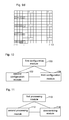
- Fig. 4a shows a schematic diagram of a reference signal mapping pattern of antenna port 0
- Fig. 4b shows a schematic diagram of a reference signal mapping pattern of antenna port 1.
- R 0 represents a common reference signal of antenna port 0
- L 0 represents a dedicated reference signal of layer 0 of a user
- the number of OFDM symbols for transmitting control information is 3, that is, the number of control symbols is 3
- L 0 is used for demodulating broadcast data and service data
- the antenna port 0 carries the user-dedicated reference signals of the layer 0.
- a base station transmits data of the service channel by using the layer 0 and layer 1.
- the interval between neighboring user-dedicated reference signals on the same sub-carrier is 6 OFDM symbols.
- the minimal interval between user-dedicated reference signals on the same OFDM symbol or different OFDM symbols is 4 sub-carriers.
- R 1 represents a common reference signal of antenna port 1
- L 1 represents a user-dedicated reference signal
- the number of OFDM symbols for transmitting control information is 3, that is, the number of control symbols is 3
- the user-dedicated reference signals L 0 and L 1 are used for demodulating broadcast data and service data of layer 0 and layer 1.
- the number of layer of user-dedicated reference signals of the antenna port 0 is 1.
- a base station transmits data of the service channel by using layer 0 and layer 1.
- the interval between neighboring user-dedicated reference signals on the same sub-carrier is 6 OFDM symbols.
- the minimal interval between user-dedicated reference signals on the same OFDM symbol or different OFDM symbols is 4 sub-carriers.
- the number of the OFDM symbols for transmitting control information is 3 and the number of layers for transmitting service data is 2 (antenna port 0 and antenna port 1 respectively use one layer of the service channel to transmit service data).
- the reference signals on the service symbols are in the form of frequency division multiplexing.
- the number of transmitting antennas is 4, the service data is transmitted in the manner of transmit diversity and the control information is transmitted in the manner of transmit diversity, the Physical Control Format Indicator Channel (PCFICH) notifies a current sub-frame that there are 3 OFDM symbols for transmitting control information, and both the number of channel layers for transmitting service data and that for transmitting broadcast data are two, in this way, the specific steps for realizing reference signal configuration and demodulation are as follows:
- Fig. 6a shows a schematic diagram of a reference signal mapping pattern of antenna port 0
- Fig. 6b shows a schematic diagram of a reference signal mapping pattern of antenna port 1.
- R 0 represents a common reference signal of antenna port
- L 0,1 represents a user-dedicated reference signal
- the number of OFDM symbols for transmitting control information is 3, that is, the number of control symbols is 3
- the user-dedicated reference signals L 0,1 are used for demodulating broadcast data and service data of layer 0 and layer 1. Since the number of layers of the user-dedicated reference signals is configured the same as the number of channel layers for transmitting service data in the service channel, a base station transmits data of the service channel by using layer 0 and layer 1.
- the interval between neighboring user-dedicated reference signals on the same sub-carrier is 5 OFDM symbols.
- the minimal interval between user-dedicated reference signals on the same OFDM symbol or different OFDM symbols is 4 sub-carriers.
- R 0 represents a common reference signal of antenna port 1
- L 0,1 represents a user-dedicated reference signal
- the number of OFDM symbols for transmitting control information is 3, that is, the number of control symbols is 3
- the user-dedicated reference signals L 0 and L 1 are used for demodulating broadcast data and service data of layer 0 and layer 1.
- the number of layers of the user-dedicated reference signals of antenna port 0 is 2.
- the base station transmits data of the service channel by using layer 0 and layer 1.
- the interval between neighboring user-dedicated reference signals on the same sub-carrier is 5 OFDM symbols.
- the minimal interval between user-dedicated reference signals on the same OFDM symbol or different OFDM symbols is 4 sub-carriers.
- the number of the OFDM symbols for transmitting control information is 3 and the number of layers for transmitting service data is 2 (antenna port 0 and antenna port 1 respectively use two layers of the service channel to transmit service data).
- the reference signals on service symbols are in the form of Code Division Multiplexing (CDM).
- the service data is transmitted in the manner of spatial multiplexing.
- the control information is transmitted in the manner of transmit diversity.
- the number of separable layers of a spatial channel corresponding to a UE is 2, and the data stream of the UE is mapped to the two transmission layers.
- the PCFICH notifies a current sub-frame that there are 3 OFDM symbols for transmitting control information. In this way, the specific steps for realizing reference signal configuration and demodulation are as follows:
- R 0 represents a common reference signal of antenna port 0
- L 0 ⁇ 3 represents a user-dedicated reference signal
- the number of OFDM symbols for transmitting control information is 3, that is, the number of control symbols is 4
- L 0 ⁇ 3 further represents that layer 0, layer 1, layer 2 and layer 3 of the user-dedicated reference signals are used for demodulating broadcast data and service data, the number of layers of the user-dedicated reference signals of the antenna port 0 is 4.
- a base station transmits data of the service channel by using layer 0, layer 1, layer 2 and layer 3.
- the interval between neighboring user-dedicated reference signals on the same sub-carrier is 5 OFDM symbols
- the minimal interval between user-dedicated reference signals on the same OFDM symbol or different OFDM symbols is 3 sub-carriers.
- R 0 represents a common reference signal of antenna port 1
- L 0 ⁇ 3 represents a user-dedicated reference signal
- the number of OFDM symbols for transmitting control information is 3, that is, the number of control symbols is 4
- L 0 ⁇ 3 further represents that layer 0, layer 1, layer 2 and layer 3 of the user-dedicated reference signals are used for demodulating broadcast data and service data, the number of layers of the user-dedicated reference signals of the antenna port 0 is 4.
- a base station transmits data of the service channel by using layer 0, layer 1, layer 2 and layer 3.
- the interval between neighboring user-dedicated reference signals on the same sub-carrier is 5 OFDM symbols
- the minimal interval between user-dedicated reference signals on the same OFDM symbol or different OFDM symbols is 3 sub-carriers.
- the number of the OFDM symbols for transmitting control information is 3 and the number of layers for transmitting the service data is 4 (antenna port 0 and antenna port 1 respectively use 4 transmission layers to transmit the service data).
- the reference signals on the service symbols are in the form of code division multiplexing.
- the number of transmitting antennas is 8
- the service data is transmitted in the manner of spatial multiplexing
- the control information and the broadcast information are transmitted in the manner of transmit diversity
- the PCFICH notifies a current sub-frame that there are 3 OFDM symbols for transmitting the control information, in this way, the specific steps for realizing reference signal configuration and demodulation are as follows:
- R 0 represents a common reference signal of antenna port 0
- L 0 represents a user-dedicated reference signal
- the number of OFDM symbols for transmitting control information is 2, that is, the number of control symbols is 2
- L 0 further represents the user-dedicated reference signal for demodulating broadcast data and service data.
- the antenna port 0 carriers the user-dedicated reference signal of layer 0.
- a base station transmits data of the service channel by using layer 0 and layer 1.
- the interval between neighboring user-dedicated reference signals on the same sub-carrier is 6 OFDM symbols
- the minimal interval between user-dedicated reference signals on the same OFDM symbol or different OFDM symbols is 4 sub-carriers.
- R 1 represents a common reference signal of antenna port 1
- L 1 represents a user-dedicated reference signal of the first layer
- the number of OFDM symbols for transmitting control information is 2, that is, the number of control symbols is 2
- L 0 and L 1 are used for demodulating broadcast data and service data.
- the antenna port 1 carries the user-dedicated reference signal of the first layer.
- a base station transmits service data by using the first layer 1 of the service channel.
- the interval between neighboring user-dedicated reference signals on the same sub-carrier is 6 OFDM symbols
- the minimal interval between user-dedicated reference signals on the same OFDM symbol or different OFDM symbols is 4 sub-carriers.
- the number of the OFDM symbols for transmitting control information is 2 and the number of layers for transmitting service data is 2 (antenna port 0 and antenna port 1 respectively use one layer to transmit the service data).
- the reference signals on the service symbols are in the form of FDM.
- the number of transmitting antennas is 4, the service data is transmitted in the manner of transmit diversity and the control information is transmitted in the manner of transmit diversity; there are 2 layers respectively for the service data and the broadcast data.
- the PCFICH notifies a current sub-frame that there are 2 OFDM symbols for transmitting control information.
- the specific steps for realizing reference signal configuration and demodulation are as follows:
- R 0 represents a common reference signal of antenna port 0,
- L 0,1 represents a user-dedicated reference signal.
- the user-dedicated reference signal L 0,1 is used for demodulating broadcast data and service data.
- the antenna port 0 carries user-dedicated reference signals of two layers. It can be seen from Fig. 9a that the interval between neighboring user-dedicated reference signals on the same sub-carrier is 5 OFDM symbols, and the minimal interval between user-dedicated reference signals on the same OFDM symbol or different OFDM symbols is 4 sub-carriers.
- R 1 represents a common reference signal of antenna port 1
- L 0,1 represents a user-dedicated reference signal
- the number of OFDM symbols for transmitting control information is 4, that is, the number of control symbols is 4
- the number of service symbols is 10
- the user-dedicated reference signal L 0,1 is used for demodulating broadcast data and service data.
- the interval between neighboring user-dedicated reference signals on the same sub-carrier is 5 OFDM symbols
- the minimal interval between user-dedicated reference signals on the same OFDM symbol or different OFDM symbols is 4 sub-carriers.
- R 2 represents a common reference signal of antenna port 2
- L 0,1 represents a user-dedicated reference signal
- the number of OFDM symbols for transmitting control information is 4, that is, the number of control symbols is 4
- the number of service symbols is 10
- the user-dedicated reference signal L 0,1 is used for demodulating broadcast data and service data.
- the interval between neighboring user-dedicated reference signals on the same sub-carrier is 5 OFDM symbols
- the minimal interval between user-dedicated reference signals on the same OFDM symbol or different OFDM symbols is 4 sub-carriers.
- R 3 represents a common reference signal of antenna port 3
- L 0,1 represents a user-dedicated reference signal
- the number of OFDM symbols for transmitting control information is 4, that is, the number of control symbols is 4
- the number of service symbols is 10
- the user-dedicated reference signal L 0,1 is used for demodulating broadcast data and service data.
- the interval between neighboring user-dedicated reference signals on the same sub-carrier is 5 OFDM symbols
- the minimal interval between user-dedicated reference signals on the same OFDM symbol or different OFDM symbols is 4 sub-carriers.
- the number of the OFDM symbols for transmitting control information is 4 and the number of layers for transmitting service data is 2 (antenna port 0 and antenna port 1 respectively use 2 transmission channel layers to transmit the service data).
- the reference signals on the service symbols are in the form of CDM.
- the number of transmitting antennas is 8, the service data is transmitted in the manner of spatial multiplexing and the control information is transmitted in the manner of transmit diversity; there are 2 separable layers of a spatial channel corresponding to a UE, and the data stream of the UE is mapped to the two transmission layers; the PCFICH notifies a current sub-frame that there are 4 OFDM symbols for transmitting control information.
- the specific steps for realizing reference signal configuration and demodulation are as follows:
- Fig. 10 shows a structure block diagram of a base station according to an embodiment of the present disclosure.
- the base station comprises:
- the base station may further comprise a third configuration module 104 for configuring a channel identifier for the broadcast channel, and sending the channel identifier to the base station and a user, wherein the channel identifier can be scrambled by the base station.
- the channel identifier may be a radio network temporary identifier.
- Fig. 11 shows a structure block diagram of a user equipment according to an embodiment of the present disclosure.
- the UE comprises:
- the UE further comprises a descrambling module 114 for descrambling a channel identifier of the broadcast channel carried on the service symbols to receive broadcast information.
- a descrambling module 114 for descrambling a channel identifier of the broadcast channel carried on the service symbols to receive broadcast information.
- a processing system of demodulate reference signal of the present disclosure is as shown in Fig. 12 , comprising a base station 120 and a UE 122, wherein the base station 120 may be the base station as shown in Fig. 10 and the UE 122 may be the UE as shown in Fig. 11 . Therefore, it is unnecessary to go into details here.
- Fig. 10 and Fig. 11 show the devices corresponding to the aforementioned methods.
- the working process and working principles of the devices are described in details in the methods, which can refer to the description of the corresponding parts in the methods. Therefore, it is unnecessary to go into details here.
- the objective of reducing the overhead of reference signals can be achieved by respectively designing the reference signals on the service symbols and that on the control symbols.
- the reference signals on the broadcast channel and the reference signals on the service channel are designed uniformly, so that the design of the reference signals on the service symbols is simplified, and the overhead of reference signals is reduced while the transmit diversity performance is not evidently reduced for the virtual antenna mapping technology.
- this disclosure relates to the design of a demodulate reference signal (DMRS) in the multi-antenna communication system, the present disclosure can be applied to a multiple input multiple output system (MIMO) with multiple transmitting antennas.
- MIMO multiple input multiple output system
Landscapes
- Engineering & Computer Science (AREA)
- Signal Processing (AREA)
- Computer Networks & Wireless Communication (AREA)
- Computer Security & Cryptography (AREA)
- Mobile Radio Communication Systems (AREA)
- Radio Transmission System (AREA)
Abstract
Description
- The present disclosure relates to the field of communications, particularly to a processing method and system of demodulate reference signal, a base station and a user equipment.
- At present, demodulation of broadcast information and control information in a Long Term Evolution (LTE) system is achieved by a common reference signal. In order to guarantee reliable transmission of control information, the LTE system can transmit control data in the manner of Space-Frequency Block Code (SFBC) or in the manner of SFBC combined with Frequency Switched Transmit Diversity (SFBC +FSTD).
- During transmission of service data, a service channel can transmit the service data in the manner of transmit diversity, spatial multiplexing or Beam Forming (BF). If the spatial multiplexing or transmit diversity is applied by the service channel, a User Equipment (UE) needs to use a common reference signal of a cell to demodulate the service data. If the service channel applies the manner of BF, the UE can utilize an existing user-dedicated reference signal to demodulate the service data.
- In practical applications, with the increase of transmitting antennas, the overheard of reference signals is correspondingly increased. Taking a 4-antenna reference signal pattern in the LTE system as an example, the proportion of the overhead of reference signals in every Resource Block (RB) is 14.29%. If reference signals of 8 antennas are extended in this way, the overhead of the reference signals will be increased and the resources applied to data transmission will be correspondingly reduced, thus influencing the data transmission efficiency of the whole system. Increasing the number of user-dedicated reference signals to realize reference signal transmission will also result in extra overhead of reference signals. Taking a 4-antenna port as an example, the overhead of reference signals may account for as much as 21.43% of a total overhead. In addition, in the case that the service channel transmits service data in the manner of the spatial multiplexing, there is no change in the overhead of reference signals when the channel does not have sufficient separability. Therefore, such reference signal design bound with the number of antennas cannot take a specific spatial channel into consideration, which is bad in flexibility and increases the overhead of reference signals, thereby reducing the transmission efficiency.
- Currently, there is no effective solution for solving the problem of low data transmission efficiency caused by large transmission overhead of reference signals in relevant technologies.
- In order to solve the problem of low data transmission efficiency caused by large transmission overhead of reference signals in relevant technologies, the present disclosure provides a configuring method of demodulate reference signal, which can reduce the overhead of reference signals.
- In order to solve the problem of low data transmission efficiency caused by large transmission overhead of reference signals in relevant technologies, the present disclosure further provides a demodulation method of demodulate reference signal, which can reduce the overhead of reference signals.
- In order to solve the problem of low data transmission efficiency caused by large transmission overhead of reference signals in relevant technologies, the present disclosure further provides a base station, which can reduce the overhead of reference signals.
- In order to solve the problem of low data transmission efficiency caused by large transmission overhead of reference signals in relevant technologies, the present disclosure further provides a UE, which can reduce the overhead of reference signals.
- In order to solve the problem of low data transmission efficiency caused by large transmission overhead of reference signals in relevant technologies, the present disclosure further provides a processing method of demodulate reference signal, which can reduce the overhead of reference signals.
- In order to solve the problem of low data transmission efficiency caused by large transmission overhead of reference signals in relevant technologies, the present disclosure further provides a processing system of demodulate reference signal, which can reduce the overhead of reference signals.
- The technical solutions of the present disclosure are realized as follows.
- The present disclosure provides a configuring method of demodulate reference signal, including:
- configuring, by a base station, common reference signals on control symbols and user-dedicated reference signals on service symbols;
- wherein the control symbols are Orthogonal Frequency Division Multiplexing (OFDM) symbols carrying control information, and the service symbols are OFDM symbols without carrying control information.
- The method may further include: making, by the base station, a control channel for transmitting the control information carried on the control symbols.
- Furthermore, an interval between neighboring user-dedicated reference signals on a same sub-carrier may be N OFDM symbols, wherein N is 4, 5, 6 or 7;
a minimal interval between user-dedicated reference signals on a same OFDM symbol or different OFDM symbols may be M sub-carriers, wherein M=3 or 4. - The method may further include: making, by the base station, a broadcast channel for transmitting broadcasting information and a service channel for transmitting service data carried on the service symbols.
- The method may further include: when the user-dedicated reference signals are configured on the service symbols, configuring a number of layers of the user-dedicated reference signals as same as a number of channel layers for transmitting the service data in the service channel to obtain layered user-dedicated reference signals, and using the layered user-dedicated reference signals to demodulate the service data and the broadcast information.
- The method may further include: configuring by the base station a channel identifier for the broadcast channel, wherein the channel identifier can be scrambled by the base station.
- Further, the channel identifier may be a radio network temporary identifier.
- The present disclosure further provides a demodulating method of demodulate reference signal, including:
- demodulating, by a UE, control information by using common reference signals configured on control symbols, and demodulating service data and broadcast data by using user-dedicated reference signals configured on service symbols;
- wherein the control symbols are OFDM symbols carrying control information and the service symbols are OFDM symbols without carrying control information.
- The method may further include: using, by the UE, a channel identifier of a broadcast channel to descramble broadcast information carried on the service symbols to receive the broadcast information.
- The present disclosure further provides a processing method of demodulate reference signal, including:
- configuring, by a base station, common reference signals on control symbols and user-dedicated reference signals on service symbols;
- demodulating, by a UE, control information by using the common reference signals and demodulating service data and broadcast data by using the user-dedicated reference signals;
- wherein the control symbols are OFDM symbols carrying control information and the service symbols are OFDM symbols without carrying control information.
- The present disclosure further provides a base station, including:
- a first configuration module for configuring common reference signals on control symbols;
- a second configuration module for configuring user-dedicated reference signals on service symbols, and making a broadcast channel and a service channel carried on the service symbols, wherein the broadcast channel is configured to transmit broadcast information and the service channel is configured to transmit service data;
- wherein the control symbols are OFDM symbols carrying control information and the service symbols are OFDM symbols without carrying control information.
- Further, an interval between neighboring user-dedicated reference signals on a same sub-carrier may be N OFDM symbols, wherein N= 4,5, 6 or 7;
a minimal interval between user-dedicated reference signals on a same OFDM symbol or different OFDM symbols may be M sub-carriers, wherein M=3 or 4. - The present disclosure further provides a UE, including:
- a first processing module for demodulating control information by using common reference signals configured on control symbols;
- a second processing module for demodulating service data and broadcast information by using user-dedicated reference signals configured on service symbols;
- wherein the control symbols are OFDM symbols carrying control information and the service symbols are OFDM symbols without carrying control information.
- The present disclosure further provides a processing system of demodulate reference signal, including a base station and a UE, wherein
- the base station is configured to configure common reference signals on control symbols and user-dedicated reference signals on service symbols, and the base station includes:
- a first configuration module for configuring the common reference signals on the control symbols;
- a second configuration module for configuring the user-dedicated reference signals on the service symbols, and making a broadcast channel and a service channel carried on the service symbols;
- the UE configured to demodulate control information by using the common reference signals, and to demodulate service data and broadcast data by using the user-dedicated reference signals, and the UE includes:
- a first processing module for demodulating the control information by using the common reference signals configured on the control symbols;
- a second processing module for demodulating the service data and broadcast information by using the user-dedicated reference signals configured on the service symbols;
- wherein the control symbols are OFDM symbols carrying control information and the service symbols are OFDM symbols without carrying control information.
- With at least one aforementioned technical solution of the present disclosure, the objective of reducing the overhead of reference signals can be achieved by respectively designing the reference signals on the service symbols and that on the control symbols. In addition, the reference signals on the broadcast channel and the reference signals on the service channel are designed uniformly, so that the design of the reference signals on the service symbols is simplified, and the overhead of reference signals is reduced while the transmit diversity performance is not evidently reduced for the virtual antenna mapping technology.
-
-
Fig. 1 shows a flowchart of a configuring method of demodulate reference signal according to an embodiment of the present disclosure; -
Fig. 2 shows a flowchart of a demodulation method of demodulate reference signal according to an embodiment of the present disclosure; -
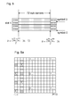
Fig. 3 shows a transmit diversity scheme using virtual antenna port mapping according to an embodiment of the present disclosure; -
Fig. 4a shows a schematic diagram of a reference signal mapping pattern ofantenna port 0 according to example 1 of the present disclosure; -
Fig. 4b shows a schematic diagram of a reference signal mapping pattern ofantenna port 1 according to example 1 of the present disclosure; -
Fig. 5 shows a schematic diagram of time-frequency resources occupied by broadcast information according to an embodiment of the present disclosure; -
Fig. 6a shows a schematic diagram of a reference signal mapping pattern ofantenna port 0 according to example 2 of the present disclosure; -
Fig. 6b shows a schematic diagram of a reference signal mapping pattern ofantenna port 1 according to example 2 of the present disclosure; -
Fig. 7a shows a schematic diagram of a reference signal mapping pattern ofantenna port 0 according to example 3 of the present disclosure; -
Fig. 7b shows a schematic diagram of a reference signal mapping pattern ofantenna port 1 according to example 3 of the present disclosure; -
Fig. 8a shows a schematic diagram of a reference signal mapping pattern ofantenna port 0 according to example 4 of the present disclosure; -
Fig. 8b shows a schematic diagram of a reference signal mapping pattern ofantenna port 1 according to example 4 of the present disclosure; -
Fig. 9a shows a schematic diagram of a reference signal mapping pattern ofantenna port 0 according to example 5 of the present disclosure; -
Fig. 9b shows a schematic diagram of a reference signal mapping pattern ofantenna port 1 according to example 5 of the present disclosure; -
Fig. 9c shows a schematic diagram of a reference signal mapping pattern ofantenna port 2 according to example 5 of the present disclosure; -
Fig. 9d shows a schematic diagram of a reference signal mapping pattern ofantenna port 3 according to example 5 of the present disclosure; -
Fig. 10 shows a structure block diagram of a base station according to an embodiment of the present disclosure; -
Fig. 11 shows a structure block diagram of a user equipment according to an embodiment of the present disclosure; and -
Fig. 12 shows a structure block diagram of a processing system of demodulate reference signal according to an embodiment of the present disclosure. - A processing method of demodulate reference signal of the present disclosure is: taking OFDM symbols carrying control information as control symbols, wherein the number of the OFDM symbols is notified by a Physical Control Format Indicator Channel (PCFICH); taking the remaining OFDM symbols (i.e. the OFDM symbols without carrying control information) as service symbols; configuring common reference signals on the control symbols and configuring user-dedicated reference signals on the service symbols to effectively reduce the overhead of the reference signals and correspondingly increase the data transmission efficiency of the system. A processing procedure of the present disclosure is described hereinafter from two aspects, i.e. reference signal configuration and reference signal demodulation.
-
Fig. 1 shows a flowchart of a configuring method of demodulate reference signal according to an embodiment of the present disclosure. This flow is performed on a base station side. As shown inFig. 1 , the configuring method of demodulate reference signal of the present disclosure comprises: - step S101: the base station configures common reference signals on control symbols and makes a control channel for transmitting control information carried on the control symbols;
- The broadcast channel can be configured with a channel identifier. For example, a Radio Network Temporary Identifier (RNTI) can be used as an identifier of the broadcast channel. The channel identifier is sent to the base station and the user so that the base station can perform scrambling on the channel identifier.
- In actual applications, transmission methods of the broadcast channel, the control channel and the service channel can be different to a certain extent. Specifically, the broadcast channel and the control channel are transmitted in the manner of transmit diversity and the service channel is sent in the manner of transmit diversity or spatial multiplexing. The broadcast channel and the service channel should be transmitted on the service symbols. Preferably, in the present disclosure, the base station configures layered user-dedicated reference signals on the service symbols: the number of layers of the user-dedicated reference signals can be equal to the number of channel layers for transmitting service data in the service channel, that is, the service data can be transmitted in the manner of spatial multiplexing or transmit diversity. In addition, the reference signal design for spatial multiplexing is related to the number of separable layers of the spatial channel. In the case that the transmit diversity is applied, the service data can be transmitted in the manner of virtual antenna mapping, and control information can be transmitted in the manner of transmit diversity, moreover, the reference signal is related to an antenna port (or a virtual antenna port).
- By the aforementioned reference signal configuration scheme, the overhead of reference signals is reduced to a certain extent. More specifically, the comparison of overhead of reference signals of 4 transmitting antennas between traditional LTE and the present disclosure is as shown in Table 1 (control data are transmitted by two antenna ports):
Table 1 Transmission manner The number of transmission layers Overhead of reference signals Traditional LTE The present disclosure Transmit diversity 1 24/168 20/168+0.01 Spatial multiplexing 4 24/168 20/168+0.01 Spatial multiplexing 2 24/168 20/168+0.01 Spatial multiplexing 1 24/168 20/168+0.01 BF 1 36/128 20/168+0.01 BF 2 Not support 20/168+0.01 - In Table 1, the "0.01" in an improved overhead of reference signals of the present disclosure is an overhead reserved for measuring a reference signal (actual overhead is smaller than 0.01). In addition, as shown in Table 1, the overhead of reference signals is determined according to the number of separable layers so that the BF of multiple streams can be supported to overcome the shortage of the LTE that it only supports the BF of a single stream, thus avoiding the problem that the fixed reference signal pattern in relevant technologies is only related to the number of antennas which influences the flexibility of reference signal configuration.
- It can be seen that the present disclosure respectively designs reference signals on service symbols and on control symbols to make overhead of reference signals reduced. Further, the design of reference signals on the service symbols can be simplified by uniformly designing reference signals of the broadcast channel and the service channel. By applying the configuring method of demodulate reference signal of the present disclosure, control information is demodulated still by common reference signals, while service data (broadcast information can be taken as special service data in the service symbols, namely the data received by every UE) are demodulated by layered user-dedicated reference signals, thus reducing the overhead of reference signals without evidently reducing the transmit diversity performance of the virtual antenna mapping technology. Therefore, the broadcast channel and the control channel apply relatively fixed virtual antenna mapping manner (e.g. 2 antenna ports and 4 antenna ports) to realize transmit diversity. The broadcast channel and the control channel can be SFBC or SFBC+ Phase Shift Diversity (PSD), or other forms. The reference signal pattern of the RB where the broadcast channel is located is the same as the reference signal pattern of the RB where the service data are located.
-
Fig. 2 shows a flowchart of a demodulation method of demodulate reference signal according to an embodiment of the present disclosure. The flow is performed on a UE side. As shown inFig. 2 , the demodulation method of demodulate reference signal comprises: - step S201: the UE demodulates control information by using common reference signals configured on control symbols;
- step S203: the UE demodulates service data and broadcast data by using user-dedicated reference signals configured on service symbols.
- Furthermore, when the reference signal demodulation is performed, a base station can perform scrambling on a broadcast channel identifier during reference signal transmission, therefore, the UE needs to descramble the broadcast channel identifier of the broadcast channel carried on the service symbols when it receives the reference signals. For example, a common RNTI is used as a channel identifier of the broadcast channel, the common RNTI is known to all UEs, and each UE uses the common RNTI to perform descrambling.
- In addition, for the receiving side, the UE obtains transmitted data of all physical antennas without need of splitting data while only needing to estimate a comprehensive Hnm (n is the number of a receiving antenna and m is the port number of a transmitting antenna) by using the reference signals. For example, Hn1 is corresponding to the comprehensive channel response of Tx0 and Tx3, i.e. hn1 = hn1+ hn3eiθ
1 and then Alamouti decoding is performed. In this way, the UE can receive broadcast information and control information by using a diversity receiving method involving two antennas of the LTE, e.g. the diversity receiving method involving 2 virtual antennas as shown inFig. 3 . - According to the aforementioned embodiment, the present disclosure further provides a processing method of demodulate reference signal, comprising:
- a base station configures common reference signals on control symbols and configures user-dedicated reference signals on service symbols; the UE demodulates control information by using the common reference signals and demodulates service data and broadcast data by using the user-dedicated reference signals;
- wherein the control symbols are Orthogonal Frequency Division Multiplexing (OFDM) symbols carrying control information, and the service symbols are OFDM symbols without carrying control information.
- The configuration and demodulation processes of demodulate reference signal of the present disclosure are described hereinafter with examples.
-
Fig. 4a shows a schematic diagram of a reference signal mapping pattern ofantenna port 0, andFig. 4b shows a schematic diagram of a reference signal mapping pattern ofantenna port 1. - As shown in
Fig. 4a , R0 represents a common reference signal ofantenna port 0, L0 represents a dedicated reference signal oflayer 0 of a user, the number of OFDM symbols for transmitting control information is 3, that is, the number of control symbols is 3, and the number of service symbols is 11, wherein the control symbols are OFDM symbols numbered with I=0, 1, 2, and the service symbols are OFDM symbols numbered with I=3∼13. In addition, L0 is used for demodulating broadcast data and service data, theantenna port 0 carries the user-dedicated reference signals of thelayer 0. Since the number of layers of the user-dedicated reference signals is configured the same as the number of channel layers used for transmitting service data in the service channel, a base station transmits data of the service channel by using thelayer 0 andlayer 1. In addition, it can be seen fromFig. 4a that the interval between neighboring user-dedicated reference signals on the same sub-carrier is 6 OFDM symbols. The minimal interval between user-dedicated reference signals on the same OFDM symbol or different OFDM symbols is 4 sub-carriers. - As shown in
Fig. 4b , R1 represents a common reference signal ofantenna port 1, L1 represents a user-dedicated reference signal, the number of OFDM symbols for transmitting control information is 3, that is, the number of control symbols is 3, and the number of service symbols is 11, wherein the control symbols are OFDM symbols numbered with I=0, 1, 2, and the service symbols are OFDM symbols numbered with I=3∼13. The user-dedicated reference signals L0 and L1 are used for demodulating broadcast data and service data oflayer 0 andlayer 1. The number of layer of user-dedicated reference signals of theantenna port 0 is 1. Since the number of layers of the user-dedicated reference signals is configured the same as the number of channel layers for transmitting service data in the service channel, a base station transmits data of the service channel by usinglayer 0 andlayer 1. In addition, it can be seen fromFig. 4b that the interval between neighboring user-dedicated reference signals on the same sub-carrier is 6 OFDM symbols. The minimal interval between user-dedicated reference signals on the same OFDM symbol or different OFDM symbols is 4 sub-carriers. - In this example, the number of the OFDM symbols for transmitting control information is 3 and the number of layers for transmitting service data is 2 (
antenna port 0 andantenna port 1 respectively use one layer of the service channel to transmit service data). The reference signals on the service symbols are in the form of frequency division multiplexing. For example, the number of transmitting antennas is 4, the service data is transmitted in the manner of transmit diversity and the control information is transmitted in the manner of transmit diversity, the Physical Control Format Indicator Channel (PCFICH) notifies a current sub-frame that there are 3 OFDM symbols for transmitting control information, and both the number of channel layers for transmitting service data and that for transmitting broadcast data are two, in this way, the specific steps for realizing reference signal configuration and demodulation are as follows: - step 1: a sender (e.g. a base station) maps a reference signal sequence (common reference signals and user-dedicated reference signals) to corresponding time-frequency resources according to the reference signal patterns of
Fig. 4a and Fig. 4b ; - step 2: the sender performs resource mapping for the broadcast data according to the reference signal patterns of the service symbols and performs scrambling by using a configured common RNTI to ensure that all UEs can receive broadcast information.
Fig. 5 shows a schematic diagram of the time-frequency resources occupied by the broadcast information. The data at this time-frequency location need to be configured to be received by all UEs; - step 3: the sender maps the control information to the control symbols according to the common reference signal pattern on the control symbols and applies virtual antenna transmit diversity or other transmit diversity schemes, such as

- step 4: the user-dedicated reference signals carried on the service symbols apply patterns of FDM access; and resource mapping is performed on the service data at the sender according to the reference signal patterns of two antenna ports (
antenna port 0 and antenna port 1), as shown inFig. 4a and Fig. 4b ; - step 5: the UE receives the broadcast information according to a predetermined RNTI, acquires information related to antennas and bandwidth, determines the reference signal pattern of the control symbols according to the number of the antennas, and determines the number of downlink available resource blocks and the frequency resources of the whole bandwidth according to the bandwidth; as for the broadcast data, since the transmit diversity scheme is applied, the number of layers is not the number of separable layers of a spatial channel, but the number of antenna ports (or virtual ports) applied to the transmit diversity;
- step 6: the UE detects the PCFICH on the first OFDM symbol and determines the number of the OFDM symbols for transmitting the control information; the UE detects its corresponding control information on corresponding OFDM symbols, including Downlink Control Information (DCI);
- step 7: the UE performs channel estimation according to the reference signal patterns as shown in
Fig. 4a and Fig. 4b and thus receives service data on a corresponding RB according to the received DCI. -
Fig. 6a shows a schematic diagram of a reference signal mapping pattern ofantenna port 0, andFig. 6b shows a schematic diagram of a reference signal mapping pattern ofantenna port 1. - As shown in
Fig. 6a , R0 represents a common reference signal ofantenna port 0, L0,1 represents a user-dedicated reference signal, the number of OFDM symbols for transmitting control information is 3, that is, the number of control symbols is 3, and the number of service symbols is 11, wherein the control symbols are OFDM symbols numbered with I=0, 1, 2 and the service symbols are OFDM symbols numbered with I=3-13. In addition, the user-dedicated reference signals L0,1 are used for demodulating broadcast data and service data oflayer 0 andlayer 1. Since the number of layers of the user-dedicated reference signals is configured the same as the number of channel layers for transmitting service data in the service channel, a base station transmits data of the service channel by usinglayer 0 andlayer 1. In addition, it can be seen fromFig. 6a that the interval between neighboring user-dedicated reference signals on the same sub-carrier is 5 OFDM symbols. The minimal interval between user-dedicated reference signals on the same OFDM symbol or different OFDM symbols is 4 sub-carriers. - As shown in
Fig. 6b , R0 represents a common reference signal ofantenna port 1, L0,1 represents a user-dedicated reference signal, the number of OFDM symbols for transmitting control information is 3, that is, the number of control symbols is 3, and the number of service symbols is 11, wherein the control symbols are OFDM symbols numbered with I=0, 1, 2 and the service symbols are OFDM symbols numbered with I=3-13. The user-dedicated reference signals L0 and L1 are used for demodulating broadcast data and service data oflayer 0 andlayer 1. The number of layers of the user-dedicated reference signals ofantenna port 0 is 2. Since the number of layers of the user-dedicated reference signals is configured the same as the number of channel layers for transmitting service data in the service channel, the base station transmits data of the service channel by usinglayer 0 andlayer 1. In addition, it can be seen fromFig. 6b that the interval between neighboring user-dedicated reference signals on the same sub-carrier is 5 OFDM symbols. The minimal interval between user-dedicated reference signals on the same OFDM symbol or different OFDM symbols is 4 sub-carriers. - In this example, the number of the OFDM symbols for transmitting control information is 3 and the number of layers for transmitting service data is 2 (
antenna port 0 andantenna port 1 respectively use two layers of the service channel to transmit service data). The reference signals on service symbols are in the form of Code Division Multiplexing (CDM). The service data is transmitted in the manner of spatial multiplexing. The control information is transmitted in the manner of transmit diversity. The number of separable layers of a spatial channel corresponding to a UE is 2, and the data stream of the UE is mapped to the two transmission layers. The PCFICH notifies a current sub-frame that there are 3 OFDM symbols for transmitting control information. In this way, the specific steps for realizing reference signal configuration and demodulation are as follows: - step 1: a sender maps a reference signal sequence (common reference signals and user-dedicated reference signals) to corresponding time-frequency resources according to the reference signal patterns of
Fig. 6a andFig. 6b ; - step 2: the sender performs resource mapping for the broadcast data according to the reference signal patterns of the service symbols and performs scrambling by using a configured common RNTI to ensure that all UEs can receive the broadcast information;
- step 3: the sender maps the control information to the control symbols according to the common reference signal pattern on the control symbols and applies virtual antenna transmit diversity or other transmit diversity schemes, such as SFBC+FSTD:

- step 4: the user-dedicated reference signals carried on the service symbols apply the patterns of CDM access; as shown in
Fig. 6a andFig. 6b , the sender can perform corresponding precoding according to the number of layers allocated to the user and perform resource mapping according to the reference signal patterns of the service symbols; - step 5: the UE receives broadcast information according to a predetermined RNTI, acquires information related to antennas and bandwidth, determines the reference signal pattern of the control symbols according to the number of the antennas, and determines the number of downlink available resource blocks and the frequency resources of the whole bandwidth according to the bandwidth; as for the broadcast data, since the transmit diversity scheme is applied, the number of layers is not the number of separable layers of a spatial channel, but the number of antenna ports (or virtual ports) applied to the transmit diversity;
- step 6: the UE detects the PCFICH on the first OFDM symbol and determines the number of the OFDM symbols for transmitting control information; the UE detects its corresponding control information on corresponding OFDM symbols, including DCI;
- step 7: the UE performs channel estimation according to the reference signal patterns as shown in
Fig. 6a andFig. 6b , and receives the service data on corresponding RBs by using a Precoding Matrix Indicator (PMI) in the DCI according to the received DCI. - As shown in
Fig. 7a , R0 represents a common reference signal ofantenna port 0, L0∼3 represents a user-dedicated reference signal, the number of OFDM symbols for transmitting control information is 3, that is, the number of control symbols is 4, and the number of service symbols is 11, wherein the control symbols are OFDM symbols of I=0, 1, 2 and the service symbols are OFDM symbols of I=3-13. In addition, L0∼3 further represents thatlayer 0,layer 1,layer 2 andlayer 3 of the user-dedicated reference signals are used for demodulating broadcast data and service data, the number of layers of the user-dedicated reference signals of theantenna port 0 is 4. Since the number of layers of the user-dedicated reference signals is configured the same as the number of channel layers for transmitting service data in the service channel, a base station transmits data of the service channel by usinglayer 0,layer 1,layer 2 andlayer 3. In addition, it can be seen fromFig. 7a that the interval between neighboring user-dedicated reference signals on the same sub-carrier is 5 OFDM symbols, and the minimal interval between user-dedicated reference signals on the same OFDM symbol or different OFDM symbols is 3 sub-carriers. - As shown in
Fig. 7b , R0 represents a common reference signal ofantenna port 1, L0∼3 represents a user-dedicated reference signal, the number of OFDM symbols for transmitting control information is 3, that is, the number of control symbols is 4, and the number of service symbols is 11, wherein the control symbols are OFDM symbols numbered with I=0, 1, 2 and the service symbols are OFDM symbols numbered with I=3-13. In addition, L0∼3 further represents thatlayer 0,layer 1,layer 2 andlayer 3 of the user-dedicated reference signals are used for demodulating broadcast data and service data, the number of layers of the user-dedicated reference signals of theantenna port 0 is 4. Since the number of layers of the user-dedicated reference signals is configured the same as the number of channel layers for transmitting service data in the service channel, a base station transmits data of the service channel by usinglayer 0,layer 1,layer 2 andlayer 3. In addition, it can be seen fromFig. 7b that the interval between neighboring user-dedicated reference signals on the same sub-carrier is 5 OFDM symbols, and the minimal interval between user-dedicated reference signals on the same OFDM symbol or different OFDM symbols is 3 sub-carriers. - In this example, the number of the OFDM symbols for transmitting control information is 3 and the number of layers for transmitting the service data is 4 (
antenna port 0 andantenna port 1 respectively use 4 transmission layers to transmit the service data). The reference signals on the service symbols are in the form of code division multiplexing. For example, the number of transmitting antennas is 8, the service data is transmitted in the manner of spatial multiplexing, the control information and the broadcast information are transmitted in the manner of transmit diversity, there are 4 separable layers for the channel, the PCFICH notifies a current sub-frame that there are 3 OFDM symbols for transmitting the control information, in this way, the specific steps for realizing reference signal configuration and demodulation are as follows: - step 1: a sender maps a reference signal sequence (common reference signals and user-dedicated reference signals) to corresponding time-frequency resources according to the reference signal patterns of
Fig. 7a andFig. 7b ; - step 2: the sender performs resource mapping for the broadcast data according to the reference signal patterns of the service symbols and performs scrambling by using a special RNTI to ensure that all UEs can receive the broadcast information;
- step 3: the sender maps the control information to the control symbols according to the common reference signal pattern on the control symbols and applies virtual antenna transmit diversity or other transmit diversity schemes, such as SFBC+FSTD:

- step 4: the user-dedicated reference signals carried on the service symbols apply the patterns of CDM access; as shown in
Fig. 7a andFig. 7b , 4 resource elements (REs) are in the form of code division, and multiplex 4 layers of reference signals. In the figures, every square represents one RE. The sender can perform corresponding precoding according to the number of layers allocated to the user and perform resource mapping according to the reference signal patterns of the service symbols; - step 5: the UE receives broadcast information according to a predetermined RNTI, acquires information related to antennas and bandwidth, determines the reference signal pattern of the control symbols according to the number of the antennas, and determines the number of downlink available resource blocks and the frequency resources of the whole bandwidth according to the bandwidth; as for the broadcast data, since the transmit diversity scheme is applied, the number of layers is not the number of separable layers of a spatial channel, but the number of antenna ports (or virtual ports) applied to the transmit diversity;
- step 6: the UE detects the PCFICH on the first OFDM symbol, determines the number of the OFDM symbols for transmitting control information, and determines reference signal patterns of control symbols; the UE detects its corresponding control information on the corresponding OFDM symbols according to the reference signal pattern, including DCI;
- step 7: the UE performs channel estimation according to the reference signal patterns as shown in
Fig. 7a andFig. 7b , and receives the service data on corresponding RBs by using a PMI in the DCI according to the received DCI. - As shown in
Fig. 8a , R0 represents a common reference signal ofantenna port 0, L0 represents a user-dedicated reference signal, the number of OFDM symbols for transmitting control information is 2, that is, the number of control symbols is 2, and the number of service symbols is 12, wherein the control symbols are OFDM symbols numbered with I=0, 1 and the service symbols are OFDM symbols numbered with I=2-13. In addition, L0 further represents the user-dedicated reference signal for demodulating broadcast data and service data. Theantenna port 0 carriers the user-dedicated reference signal oflayer 0. Since the number of layers of the user-dedicated reference signals is configured the same as the number of channel layers for transmitting the service data in the service channel, a base station transmits data of the service channel by usinglayer 0 andlayer 1. In addition, it can be seen fromFig. 8a that the interval between neighboring user-dedicated reference signals on the same sub-carrier is 6 OFDM symbols, and the minimal interval between user-dedicated reference signals on the same OFDM symbol or different OFDM symbols is 4 sub-carriers. - As shown in
Fig. 8b , R1 represents a common reference signal ofantenna port 1, L1 represents a user-dedicated reference signal of the first layer, the number of OFDM symbols for transmitting control information is 2, that is, the number of control symbols is 2, and the number of service symbols is 12, wherein the control symbols are OFDM symbols numbered with I=0, 1 and the service symbols are OFDM symbols numbered with I=2-13. In addition, L0 and L1 are used for demodulating broadcast data and service data. Theantenna port 1 carries the user-dedicated reference signal of the first layer. Since the number of layers of the user-dedicated reference signals is configured the same as the number of channel layers for transmitting service data in the service channel, a base station transmits service data by using thefirst layer 1 of the service channel. In addition, it can be seen fromFig. 8b that the interval between neighboring user-dedicated reference signals on the same sub-carrier is 6 OFDM symbols, and the minimal interval between user-dedicated reference signals on the same OFDM symbol or different OFDM symbols is 4 sub-carriers. - In this example, the number of the OFDM symbols for transmitting control information is 2 and the number of layers for transmitting service data is 2 (
antenna port 0 andantenna port 1 respectively use one layer to transmit the service data). The reference signals on the service symbols are in the form of FDM. For example, the number of transmitting antennas is 4, the service data is transmitted in the manner of transmit diversity and the control information is transmitted in the manner of transmit diversity; there are 2 layers respectively for the service data and the broadcast data. This example is different from examples 1, 2 and 3 in that, the PCFICH notifies a current sub-frame that there are 2 OFDM symbols for transmitting control information. In this way, the specific steps for realizing reference signal configuration and demodulation are as follows: - step 1: a sender maps a reference signal sequence (common reference signals and user-dedicated reference signals) to corresponding time-frequency resources according to the reference signal patterns of
Fig. 8a andFig. 8b ; since the value of the PCFICH is changed, the reference signal patterns of the control symbols and the reference signal patterns of the service symbols are changed, accordingly; - step 2: the sender performs resource mapping for the broadcast data according to the reference signal patterns of the service symbols, and performs scrambling by using special RNTI to ensure that all UEs can receive the broadcast information;
- step 3: the sender maps the control information to the control symbols according to the common reference signal pattern on the control symbols and applies virtual antenna transmit diversity or other transmit diversity schemes, such as

- step 4: the user-dedicated reference signals carried on the service symbols apply the patterns of FDM access; and resource mapping is performed on the service data at the sender according to the reference signal patterns of two antenna ports (
antenna port 0 and antenna port 1), as shown inFig. 8a andFig. 8b ; - step 5: the UE receives broadcast information according to a predetermined RNTI, acquires information related to antennas and bandwidth, determines a reference signal pattern of the control symbols according to the number of the antennas, and determines the number of downlink available resource blocks and the frequency resources of the whole bandwidth according to the bandwidth; as for the broadcast data, since the transmit diversity scheme is applied, the number of layers is not the number of separable layers of a spatial channel, but the number of antenna ports (or virtual ports) applied to the transmit diversity;
- step 6: the UE detects the PCFICH on the first OFDM symbol and determines the number of OFDM symbols for transmitting control information; the UE detects its corresponding control information on the corresponding OFDM symbols, including DCI;
- step 7: the UE performs channel estimation according to the reference signal patterns as shown in
Fig. 8a andFig. 8b , and receives the service data on corresponding RBs by using an algorithm for receiving transmit diversity according to the received DCI. - As shown in
Fig. 9a , R0 represents a common reference signal ofantenna port 0, L0,1 represents a user-dedicated reference signal. In one RB, the number of OFDM symbols for transmitting control information is 4, that is, the number of control symbols is 4, and the number of service symbols is 10, wherein the control symbols are OFDM symbols numbered with I=0, 1, 2, 3 and the service symbols are OFDM symbols numbered with I=4-13. In addition, the user-dedicated reference signal L0,1 is used for demodulating broadcast data and service data. Theantenna port 0 carries user-dedicated reference signals of two layers. It can be seen fromFig. 9a that the interval between neighboring user-dedicated reference signals on the same sub-carrier is 5 OFDM symbols, and the minimal interval between user-dedicated reference signals on the same OFDM symbol or different OFDM symbols is 4 sub-carriers. - As shown in
Fig. 9b , R1 represents a common reference signal ofantenna port 1, L0,1 represents a user-dedicated reference signal, the number of OFDM symbols for transmitting control information is 4, that is, the number of control symbols is 4, and the number of service symbols is 10, wherein the control symbols are OFDM symbols numbered with I=0, 1, 2, 3 and the service symbols are OFDM symbols numbered with I=4-13. In addition, the user-dedicated reference signal L0,1 is used for demodulating broadcast data and service data. In addition, it can be seen fromFig. 9b that the interval between neighboring user-dedicated reference signals on the same sub-carrier is 5 OFDM symbols, and the minimal interval between user-dedicated reference signals on the same OFDM symbol or different OFDM symbols is 4 sub-carriers. - As shown in
Fig. 9c , R2 represents a common reference signal ofantenna port 2, L0,1 represents a user-dedicated reference signal, the number of OFDM symbols for transmitting control information is 4, that is, the number of control symbols is 4, and the number of service symbols is 10, wherein the control symbols are OFDM symbols numbered with I=0, 1, 2, 3 and the service symbols are OFDM symbols numbered with I=4-13. In addition, the user-dedicated reference signal L0,1 is used for demodulating broadcast data and service data. In addition, it can be seen fromFig. 9c that the interval between neighboring user-dedicated reference signals on the same sub-carrier is 5 OFDM symbols, and the minimal interval between user-dedicated reference signals on the same OFDM symbol or different OFDM symbols is 4 sub-carriers. - As shown in
Fig. 9d , R3 represents a common reference signal ofantenna port 3, L0,1 represents a user-dedicated reference signal, the number of OFDM symbols for transmitting control information is 4, that is, the number of control symbols is 4, and the number of service symbols is 10, wherein the control symbols are OFDM symbols numbered with I=0, 1, 2, 3 and the service symbols are OFDM symbols numbered with I=4-13. In addition, the user-dedicated reference signal L0,1 is used for demodulating broadcast data and service data. In addition, it can be seen fromFig. 9d that the interval between neighboring user-dedicated reference signals on the same sub-carrier is 5 OFDM symbols, and the minimal interval between user-dedicated reference signals on the same OFDM symbol or different OFDM symbols is 4 sub-carriers. - In this example, the number of the OFDM symbols for transmitting control information is 4 and the number of layers for transmitting service data is 2 (
antenna port 0 andantenna port 1 respectively use 2 transmission channel layers to transmit the service data). The reference signals on the service symbols are in the form of CDM. For example, the number of transmitting antennas is 8, the service data is transmitted in the manner of spatial multiplexing and the control information is transmitted in the manner of transmit diversity; there are 2 separable layers of a spatial channel corresponding to a UE, and the data stream of the UE is mapped to the two transmission layers; the PCFICH notifies a current sub-frame that there are 4 OFDM symbols for transmitting control information. In this way, the specific steps for realizing reference signal configuration and demodulation are as follows: - step 1: a sender maps a reference signal sequence (common reference signals and user-dedicated reference signals) to corresponding time frequency resources according to the reference signal patterns of
Fig. 9a ,Fig. 9b ,Fig. 9c andFig. 9d ; - step 2: the sender performs resource mapping for the broadcast data according to the reference signal patterns of the service symbols, and performs scrambling by a configured common RNTI to ensure that all UEs can receive the broadcast information;
- step 3: the sender maps the control information to the control symbols according to the common reference signal pattern on the control symbols and applies virtual antenna transmit diversity or other transmit diversity schemes, such as SFBC+FSTD:

- step 4: the user-dedicated reference signals carried on the service symbols apply the patterns of CDM access; and as shown in
Fig. 6a andFig. 6b , the sender can perform corresponding precoding according to the layers allocated to the user and perform resource mapping according to the reference signal patterns of the service symbols; - step 5: the UE receives broadcast information according to a predetermined RNTI, acquires information related to antennas and bandwidth, determines a reference signal pattern of the control symbols according to the number of the antennas, and determines the number of downlink available resource blocks and the frequency resources of the whole bandwidth according to the bandwidth; as for the broadcast data, since the transmit diversity scheme is applied, the number of layers is not the number of separable layers of a spatial channel, but the number of antenna ports (or virtual ports) applied to the transmit diversity;
- step 6: the UE detects the PCFICH on the first OFDM symbol and determines the number of OFDM symbols for transmitting control information; the UE detects its corresponding control information on the corresponding OFDM symbols, including DCI;
- step 7: the UE performs channel estimation according to the reference signal patterns as shown in
Fig. 9a ,Fig. 9b ,Fig. 9c andFig. 9d and receives the service data on corresponding RBs by using a PMI in the DCI according to the received DCI. -
Fig. 10 shows a structure block diagram of a base station according to an embodiment of the present disclosure. As shown inFig. 10 , the base station comprises: - a
first configuration module 100 for configuring common reference signals on control symbols, wherein the pattern of the common reference signals may be a current reference signal pattern of all antenna ports in the prior art; - a
second configuration module 102 for configuring user-dedicated reference signals on service symbols, and making a broadcast channel and a service channel carried on the service symbols, wherein the broadcast channel is used for transmitting broadcast information and the service channel is used for transmitting service data, wherein the control symbols are OFDM symbols carrying control information and the service symbols are OFDM symbols without carrying control information. When thesecond configuration module 102 configures user-dedicated reference signals on the service symbols, the following configuration rules may be applied: the interval between neighboring user-dedicated reference signals on the same sub-carrier is N OFDM symbols, wherein N =4, 5, 6 or 7; the minimal interval between user-dedicated reference signals on the same or different OFDM symbols is M sub-carriers, wherein M=3 or 4. Here, only the relative locations of all user-dedicated reference signals are specified, and every specific downlink-dedicated location can be flexibly configured according to the need, as long as the relative locations of all user-dedicated reference signals satisfy the aforementioned rules. In addition, the number of layers of the user-dedicated reference signals is configured the same as the number of channel layers for transmitting service data in the service channel. - Preferably, the base station may further comprise a
third configuration module 104 for configuring a channel identifier for the broadcast channel, and sending the channel identifier to the base station and a user, wherein the channel identifier can be scrambled by the base station. For example, the channel identifier may be a radio network temporary identifier. -
Fig. 11 shows a structure block diagram of a user equipment according to an embodiment of the present disclosure. As shown inFig. 11 , the UE comprises: - a
first processing module 110 for demodulating control information by using common reference signals configured on control symbols; - a
second processing module 112 for demodulating service data and broadcast data by using user-dedicated reference signals configured on service symbols; wherein the control symbols are OFDM symbols carrying control information and the service symbols are OFDM symbols without carrying control information. - Preferably, the UE further comprises a
descrambling module 114 for descrambling a channel identifier of the broadcast channel carried on the service symbols to receive broadcast information. - According to the processing method of demodulate reference signal described above, a processing system of demodulate reference signal of the present disclosure is as shown in
Fig. 12 , comprising abase station 120 and aUE 122, wherein thebase station 120 may be the base station as shown inFig. 10 and theUE 122 may be the UE as shown inFig. 11 . Therefore, it is unnecessary to go into details here. -
Fig. 10 and Fig. 11 show the devices corresponding to the aforementioned methods. The working process and working principles of the devices are described in details in the methods, which can refer to the description of the corresponding parts in the methods. Therefore, it is unnecessary to go into details here. - In conclusion, with the aforementioned technical solution of the present disclosure, the objective of reducing the overhead of reference signals can be achieved by respectively designing the reference signals on the service symbols and that on the control symbols. In addition, the reference signals on the broadcast channel and the reference signals on the service channel are designed uniformly, so that the design of the reference signals on the service symbols is simplified, and the overhead of reference signals is reduced while the transmit diversity performance is not evidently reduced for the virtual antenna mapping technology. Further, since this disclosure relates to the design of a demodulate reference signal (DMRS) in the multi-antenna communication system, the present disclosure can be applied to a multiple input multiple output system (MIMO) with multiple transmitting antennas.
- What are described above are only preferred embodiments of the present disclosure and are not for use in limiting the present disclosure. Any modification, equivalent replacement and improvement made within the principle of the present disclosure should be included in the protection scope of the present disclosure.
step S103: the base station configures user-dedicated reference signals on service symbols, and makes a broadcast channel and a service channel carried on the service symbols;
wherein the broadcast channel is used for transmitting broadcast information and the service channel is used for transmitting service data; when configuring user-dedicated reference signals on the service symbols, the following configuration rules may be applied: an interval between neighboring user-dedicated reference signals on the same sub-carrier is N OFDM symbols, wherein N =4, 5, 6 or 7; the minimal interval between user-dedicated reference signals on the same or different OFDM symbols is M sub-carriers, wherein M=3 or 4. Here only relative locations of all user-dedicated reference signals are specified. Every specific downlink-dedicated location can be flexibly configured according to the need, as long as the relative locations of all user-dedicated reference signals satisfy the aforementioned rules.
Claims (14)
- A configuring method of demodulate reference signal, comprising:configuring, by a base station, common reference signals on control symbols and user-dedicated reference signals on service symbols;wherein the control symbols are Orthogonal Frequency Division Multiplexing (OFDM) symbols carrying control information, and the service symbols are OFDM symbols without carrying control information.
- The method according to claim 1, further comprising:making, by the base station, a control channel for transmitting the control information carried on the control symbols.
- The method according to claim 1, wherein an interval between neighboring user-dedicated reference signals on a same sub-carrier is N OFDM symbols, wherein N is 4, 5, 6 or 7;
a minimal interval between user-dedicated reference signals on a same OFDM symbol or different OFDM symbols is M sub-carriers, wherein M=3 or 4. - The method according to claim 1, further comprising:making, by the base station, a broadcast channel for transmitting broadcasting information and a service channel for transmitting service data carried on the service symbols.
- The method according to claim 4, further comprising: when configuring the user-dedicated reference signals on the service symbols, configuring a number of layers of the user-dedicated reference signals as same as a number of channel layers for transmitting the service data in the service channel to obtain layered user-dedicated reference signals; and using the layered user-dedicated reference signals to demodulate the service data and the broadcast information.
- The method according to claim 3, further comprising:configuring, by the base station, a channel identifier for the broadcast channel, wherein the channel identifier can be scrambled by the base station.
- The method according to claim 6, wherein the channel identifier is a radio network temporary identifier.
- A demodulating method of demodulate reference signal, comprising:demodulating, by a UE, control information by using common reference signals configured on control symbols, and demodulating service data and broadcast data by using user-dedicated reference signals configured on service symbols;wherein the control symbols are OFDM symbols carrying control information and the service symbols are OFDM symbols without carrying control information.
- The method according to claim 8, further comprising:using, by the UE, a channel identifier of a broadcast channel to descramble broadcast information carried on the service symbols to receive the broadcast information.
- A processing method of demodulate reference signal, comprising:configuring, by a base station, common reference signals on control symbols and user-dedicated reference signals on service symbols;demodulating, by a UE, control information by using the common reference signals and demodulating service data and broadcast data by using the user-dedicated reference signals;wherein the control symbols are OFDM symbols carrying control information and the service symbols are OFDM symbols without carrying control information.
- A base station, comprising:a first configuration module for configuring common reference signals on control symbols;a second configuration module for configuring user-dedicated reference signals on service symbols, and making a broadcast channel and a service channel carried on the service symbols, wherein the broadcast channel is configured to transmit broadcast information and the service channel is configured to transmit service data;wherein the control symbols are OFDM symbols carrying control information and the service symbols are OFDM symbols without carrying control information.
- The base station according to claim 11, wherein an interval between neighboring user-dedicated reference signals on a same sub-carrier is N OFDM symbols, wherein N=4, 5, 6 or 7;
a minimal interval between user-dedicated reference signals on a same OFDM symbol or different OFDM symbols is M sub-carriers, wherein M=3 or 4. - A UE, comprising:a first processing module for demodulating control information by using common reference signals configured on control symbols;a second processing module for demodulating service data and broadcast information by using user-dedicated reference signals configured on service symbols;wherein the control symbols are OFDM symbols carrying control information and the service symbols are OFDM symbols without carrying control information.
- A processing system of demodulate reference signal, comprising a base station and a UE,
wherein the base station is configured to configure common reference signals on control symbols and user-dedicated reference signals on service symbols, and the base station comprises:a first configuration module for configuring the common reference signals on the control symbols;a second configuration module for configuring the user-dedicated reference signals on the service symbols, and making a broadcast channel and a service channel carried on the service symbols;the UE is configured to demodulate control information by using the common reference signals, and to demodulate service data and broadcast data by using the user-dedicated reference signals, and the UE comprises:a first processing module for demodulating the control information by using the common reference signals configured on the control symbols;a second processing module for demodulating the service data and broadcast information by using the user-dedicated reference signals configured on the service symbols;wherein the control symbols are OFDM symbols carrying control information and the service symbols are OFDM symbols without carrying control information.
Applications Claiming Priority (2)
| Application Number | Priority Date | Filing Date | Title |
|---|---|---|---|
| CN200910093462.1A CN102035777B (en) | 2009-09-24 | 2009-09-24 | Processing method and system and configuration method for demodulation pilot frequency, base station and user equipment |
| PCT/CN2010/071302 WO2010145254A1 (en) | 2009-09-24 | 2010-03-25 | Method and system for processing pilot demodulation, base station, user equipment thereof |
Publications (3)
| Publication Number | Publication Date |
|---|---|
| EP2469906A1 true EP2469906A1 (en) | 2012-06-27 |
| EP2469906A4 EP2469906A4 (en) | 2016-08-24 |
| EP2469906B1 EP2469906B1 (en) | 2018-08-15 |
Family
ID=43355749
Family Applications (1)
| Application Number | Title | Priority Date | Filing Date |
|---|---|---|---|
| EP10788650.9A Not-in-force EP2469906B1 (en) | 2009-09-24 | 2010-03-25 | Method and system for processing pilot demodulation, base station, user equipment thereof |
Country Status (5)
| Country | Link |
|---|---|
| US (1) | US20120195390A1 (en) |
| EP (1) | EP2469906B1 (en) |
| JP (1) | JP2013506325A (en) |
| CN (1) | CN102035777B (en) |
| WO (1) | WO2010145254A1 (en) |
Cited By (2)
| Publication number | Priority date | Publication date | Assignee | Title |
|---|---|---|---|---|
| WO2013169201A3 (en) * | 2012-05-11 | 2014-01-03 | Telefonaktiebolaget L M Ericsson (Publ) | Method and apparatus for transmitting demodulation pilots in a multi antenna wireless communication system |
| CN104105138A (en) * | 2013-04-03 | 2014-10-15 | 中兴通讯股份有限公司 | Method and device for data channel transmission and reception |
Families Citing this family (5)
| Publication number | Priority date | Publication date | Assignee | Title |
|---|---|---|---|---|
| CN102916920B (en) | 2011-08-05 | 2015-04-15 | 华为技术有限公司 | Method and device for sending pilot signal |
| CN103546413B (en) * | 2012-07-13 | 2017-02-08 | 工业和信息化部电信传输研究所 | Carrier scheme applicable to 3.5GHz TDD (time division duplexing) frequency bands |
| CN103181114B (en) * | 2012-09-04 | 2016-11-02 | 华为技术有限公司 | The transmission method of a kind of reference signal and device |
| CN109547187B (en) * | 2012-12-27 | 2022-01-14 | 华为技术有限公司 | Signal processing method and apparatus |
| US10505772B2 (en) * | 2016-10-26 | 2019-12-10 | Qualcomm Incorporated | Non-staggered reference signals and repeated pilots in orthogonal frequency-division multiplexing |
Family Cites Families (25)
| Publication number | Priority date | Publication date | Assignee | Title |
|---|---|---|---|---|
| CN1233110C (en) * | 2000-10-11 | 2005-12-21 | 三星电子株式会社 | Apparatus and method for controlling transmit antenna array for physical downlink shared channel in mobile communication system |
| US7352829B2 (en) * | 2004-01-12 | 2008-04-01 | Infineon Technologies Ag | Data-aided channel estimation |
| JP4657888B2 (en) * | 2005-10-31 | 2011-03-23 | シャープ株式会社 | Transmitter and transmission method |
| CN101064557B (en) * | 2006-04-25 | 2012-10-17 | 上海原动力通信科技有限公司 | Method for obtaining downlink channel quality information based on intelligent antenna |
| JP4447575B2 (en) * | 2006-05-01 | 2010-04-07 | 株式会社エヌ・ティ・ティ・ドコモ | Transmitting apparatus and transmitting method |
| US8144731B2 (en) * | 2006-10-24 | 2012-03-27 | Qualcomm Incorporated | Control channel signaling in wireless communications |
| CN1988408A (en) * | 2006-11-29 | 2007-06-27 | 北京邮电大学 | Antenna circulation delay diversity method for small interval and transmitting and receiving device |
| JP4583388B2 (en) * | 2007-02-05 | 2010-11-17 | 株式会社エヌ・ティ・ティ・ドコモ | Base station equipment |
| US8913695B2 (en) * | 2007-03-12 | 2014-12-16 | Qualcomm Incorporated | Hybrid pilot configuration |
| CN101330486B (en) * | 2007-06-21 | 2011-07-13 | 电信科学技术研究院 | Method and apparatus for transmitting down special pilot |
| CN101431490A (en) * | 2007-10-30 | 2009-05-13 | 大唐移动通信设备有限公司 | Pilot frequency insertion method, apparatus, base station and customer equipment of orthogonal frequency division multiplexing system |
| EP2905916A1 (en) * | 2008-03-13 | 2015-08-12 | IDTP Holdings, Inc. | Neighbour cell quality measurement in a telecommunications system |
| CN101299634A (en) * | 2008-06-19 | 2008-11-05 | 中兴通讯股份有限公司 | Transmission method of dedicated pilot in LTE system |
| KR101488028B1 (en) * | 2008-07-17 | 2015-01-30 | 엘지전자 주식회사 | A method of transmitting a reference signal in a multi-antenna system |
| WO2010024743A1 (en) * | 2008-08-27 | 2010-03-04 | Telefonaktiebolaget L M Ericsson (Publ) | Method and arrangement, cell id collision detection |
| US8315225B2 (en) * | 2008-09-22 | 2012-11-20 | Research In Motion Limited | Aspects to support LTE-A downlink hi-order MIMO |
| US20100120442A1 (en) * | 2008-11-12 | 2010-05-13 | Motorola, Inc. | Resource sharing in relay operations within wireless communication systems |
| KR101755038B1 (en) * | 2009-01-30 | 2017-07-06 | 엘지전자 주식회사 | Apparatus and method of transmitting reference signal in wireless communication system |
| KR101255459B1 (en) * | 2009-02-02 | 2013-04-16 | 후지쯔 가부시끼가이샤 | Wireless communication system, base station device, terminal device and wireless communication method employed in wireless communication system |
| KR20100089758A (en) * | 2009-02-04 | 2010-08-12 | 엘지전자 주식회사 | Apparatus and method of transmitting signal in wireless communication system |
| KR101644881B1 (en) * | 2009-04-10 | 2016-08-03 | 엘지전자 주식회사 | Apparatus and metheod for positioing a user equipment |
| US8712399B2 (en) * | 2009-05-06 | 2014-04-29 | Texas Instruments Incorporated | Coordinated multi-point transmission in a cellular network |
| US9048976B2 (en) * | 2009-06-22 | 2015-06-02 | Lg Electronics Inc. | Apparatus and method for transmitting reference signals in wireless communication system |
| CA2768349C (en) * | 2009-07-17 | 2015-09-29 | Lg Electronics Inc. | Method and apparatus for transmitting reference signal in wireless communication system including relay station |
| US8300587B2 (en) * | 2009-08-17 | 2012-10-30 | Nokia Corporation | Initialization of reference signal scrambling |
-
2009
- 2009-09-24 CN CN200910093462.1A patent/CN102035777B/en not_active Expired - Fee Related
-
2010
- 2010-03-25 US US13/259,041 patent/US20120195390A1/en not_active Abandoned
- 2010-03-25 WO PCT/CN2010/071302 patent/WO2010145254A1/en not_active Ceased
- 2010-03-25 JP JP2012530107A patent/JP2013506325A/en active Pending
- 2010-03-25 EP EP10788650.9A patent/EP2469906B1/en not_active Not-in-force
Non-Patent Citations (1)
| Title |
|---|
| See references of WO2010145254A1 * |
Cited By (4)
| Publication number | Priority date | Publication date | Assignee | Title |
|---|---|---|---|---|
| WO2013169201A3 (en) * | 2012-05-11 | 2014-01-03 | Telefonaktiebolaget L M Ericsson (Publ) | Method and apparatus for transmitting demodulation pilots in a multi antenna wireless communication system |
| US9401751B2 (en) | 2012-05-11 | 2016-07-26 | Telefonaktiebolaget Lm Ericsson (Publ) | Method and apparatus for transmitting demodulation pilots in a multi antenna wireless communication system |
| CN104105138A (en) * | 2013-04-03 | 2014-10-15 | 中兴通讯股份有限公司 | Method and device for data channel transmission and reception |
| CN104105138B (en) * | 2013-04-03 | 2019-04-05 | 中兴通讯股份有限公司 | Data channel transmission and reception processing method and device |
Also Published As
| Publication number | Publication date |
|---|---|
| JP2013506325A (en) | 2013-02-21 |
| WO2010145254A1 (en) | 2010-12-23 |
| EP2469906B1 (en) | 2018-08-15 |
| EP2469906A4 (en) | 2016-08-24 |
| US20120195390A1 (en) | 2012-08-02 |
| CN102035777B (en) | 2014-03-12 |
| CN102035777A (en) | 2011-04-27 |
Similar Documents
| Publication | Publication Date | Title |
|---|---|---|
| EP2084876B1 (en) | Method of allocating reference signals in MIMO system | |
| EP3748892B1 (en) | Antenna port mapping method and device for demodulation reference signals | |
| EP2011263B1 (en) | Allocation of reference signals in MIMO system | |
| CA2796374C (en) | Systems and methods for bundling resource blocks in a wireless communication system | |
| EP2919410B1 (en) | Base station, subscriber station, and methods for transmitting and receiving a reference signal | |
| KR20100010890A (en) | Method for transmitting reference signal in multiple antenna system | |
| EP2469906B1 (en) | Method and system for processing pilot demodulation, base station, user equipment thereof | |
| US20100085925A1 (en) | Base station | |
| EP2119072A1 (en) | A method of transmitting control channel information in an ofdm communication system downlink | |
| EP2378698B1 (en) | Systems and methods for bundling resource blocks in a wireless communication system | |
| KR20100058390A (en) | Method of transmitting reference signal in multiple antenna system |
Legal Events
| Date | Code | Title | Description |
|---|---|---|---|
| PUAI | Public reference made under article 153(3) epc to a published international application that has entered the european phase |
Free format text: ORIGINAL CODE: 0009012 |
|
| 17P | Request for examination filed |
Effective date: 20120323 |
|
| AK | Designated contracting states |
Kind code of ref document: A1 Designated state(s): AT BE BG CH CY CZ DE DK EE ES FI FR GB GR HR HU IE IS IT LI LT LU LV MC MK MT NL NO PL PT RO SE SI SK SM TR |
|
| DAX | Request for extension of the european patent (deleted) | ||
| REG | Reference to a national code |
Ref country code: DE Ref legal event code: R079 Ref document number: 602010052799 Country of ref document: DE Free format text: PREVIOUS MAIN CLASS: H04W0016000000 Ipc: H04W0048120000 |
|
| RA4 | Supplementary search report drawn up and despatched (corrected) |
Effective date: 20160727 |
|
| RIC1 | Information provided on ipc code assigned before grant |
Ipc: H04L 5/00 20060101ALI20160721BHEP Ipc: H04W 48/12 20090101AFI20160721BHEP |
|
| STAA | Information on the status of an ep patent application or granted ep patent |
Free format text: STATUS: EXAMINATION IS IN PROGRESS |
|
| 17Q | First examination report despatched |
Effective date: 20170322 |
|
| GRAP | Despatch of communication of intention to grant a patent |
Free format text: ORIGINAL CODE: EPIDOSNIGR1 |
|
| STAA | Information on the status of an ep patent application or granted ep patent |
Free format text: STATUS: GRANT OF PATENT IS INTENDED |
|
| INTG | Intention to grant announced |
Effective date: 20180508 |
|
| GRAS | Grant fee paid |
Free format text: ORIGINAL CODE: EPIDOSNIGR3 |
|
| GRAA | (expected) grant |
Free format text: ORIGINAL CODE: 0009210 |
|
| STAA | Information on the status of an ep patent application or granted ep patent |
Free format text: STATUS: THE PATENT HAS BEEN GRANTED |
|
| AK | Designated contracting states |
Kind code of ref document: B1 Designated state(s): AT BE BG CH CY CZ DE DK EE ES FI FR GB GR HR HU IE IS IT LI LT LU LV MC MK MT NL NO PL PT RO SE SI SK SM TR |
|
| REG | Reference to a national code |
Ref country code: CH Ref legal event code: EP Ref country code: GB Ref legal event code: FG4D Ref country code: AT Ref legal event code: REF Ref document number: 1031251 Country of ref document: AT Kind code of ref document: T Effective date: 20180815 |
|
| REG | Reference to a national code |
Ref country code: IE Ref legal event code: FG4D |
|
| REG | Reference to a national code |
Ref country code: DE Ref legal event code: R096 Ref document number: 602010052799 Country of ref document: DE |
|
| REG | Reference to a national code |
Ref country code: NL Ref legal event code: MP Effective date: 20180815 |
|
| REG | Reference to a national code |
Ref country code: LT Ref legal event code: MG4D |
|
| REG | Reference to a national code |
Ref country code: AT Ref legal event code: MK05 Ref document number: 1031251 Country of ref document: AT Kind code of ref document: T Effective date: 20180815 |
|
| PG25 | Lapsed in a contracting state [announced via postgrant information from national office to epo] |
Ref country code: GR Free format text: LAPSE BECAUSE OF FAILURE TO SUBMIT A TRANSLATION OF THE DESCRIPTION OR TO PAY THE FEE WITHIN THE PRESCRIBED TIME-LIMIT Effective date: 20181116 Ref country code: NO Free format text: LAPSE BECAUSE OF FAILURE TO SUBMIT A TRANSLATION OF THE DESCRIPTION OR TO PAY THE FEE WITHIN THE PRESCRIBED TIME-LIMIT Effective date: 20181115 Ref country code: BG Free format text: LAPSE BECAUSE OF FAILURE TO SUBMIT A TRANSLATION OF THE DESCRIPTION OR TO PAY THE FEE WITHIN THE PRESCRIBED TIME-LIMIT Effective date: 20181115 Ref country code: AT Free format text: LAPSE BECAUSE OF FAILURE TO SUBMIT A TRANSLATION OF THE DESCRIPTION OR TO PAY THE FEE WITHIN THE PRESCRIBED TIME-LIMIT Effective date: 20180815 Ref country code: IS Free format text: LAPSE BECAUSE OF FAILURE TO SUBMIT A TRANSLATION OF THE DESCRIPTION OR TO PAY THE FEE WITHIN THE PRESCRIBED TIME-LIMIT Effective date: 20181215 Ref country code: NL Free format text: LAPSE BECAUSE OF FAILURE TO SUBMIT A TRANSLATION OF THE DESCRIPTION OR TO PAY THE FEE WITHIN THE PRESCRIBED TIME-LIMIT Effective date: 20180815 Ref country code: LT Free format text: LAPSE BECAUSE OF FAILURE TO SUBMIT A TRANSLATION OF THE DESCRIPTION OR TO PAY THE FEE WITHIN THE PRESCRIBED TIME-LIMIT Effective date: 20180815 Ref country code: FI Free format text: LAPSE BECAUSE OF FAILURE TO SUBMIT A TRANSLATION OF THE DESCRIPTION OR TO PAY THE FEE WITHIN THE PRESCRIBED TIME-LIMIT Effective date: 20180815 Ref country code: SE Free format text: LAPSE BECAUSE OF FAILURE TO SUBMIT A TRANSLATION OF THE DESCRIPTION OR TO PAY THE FEE WITHIN THE PRESCRIBED TIME-LIMIT Effective date: 20180815 |
|
| PG25 | Lapsed in a contracting state [announced via postgrant information from national office to epo] |
Ref country code: HR Free format text: LAPSE BECAUSE OF FAILURE TO SUBMIT A TRANSLATION OF THE DESCRIPTION OR TO PAY THE FEE WITHIN THE PRESCRIBED TIME-LIMIT Effective date: 20180815 Ref country code: LV Free format text: LAPSE BECAUSE OF FAILURE TO SUBMIT A TRANSLATION OF THE DESCRIPTION OR TO PAY THE FEE WITHIN THE PRESCRIBED TIME-LIMIT Effective date: 20180815 |
|
| PG25 | Lapsed in a contracting state [announced via postgrant information from national office to epo] |
Ref country code: ES Free format text: LAPSE BECAUSE OF FAILURE TO SUBMIT A TRANSLATION OF THE DESCRIPTION OR TO PAY THE FEE WITHIN THE PRESCRIBED TIME-LIMIT Effective date: 20180815 Ref country code: PL Free format text: LAPSE BECAUSE OF FAILURE TO SUBMIT A TRANSLATION OF THE DESCRIPTION OR TO PAY THE FEE WITHIN THE PRESCRIBED TIME-LIMIT Effective date: 20180815 Ref country code: IT Free format text: LAPSE BECAUSE OF FAILURE TO SUBMIT A TRANSLATION OF THE DESCRIPTION OR TO PAY THE FEE WITHIN THE PRESCRIBED TIME-LIMIT Effective date: 20180815 Ref country code: RO Free format text: LAPSE BECAUSE OF FAILURE TO SUBMIT A TRANSLATION OF THE DESCRIPTION OR TO PAY THE FEE WITHIN THE PRESCRIBED TIME-LIMIT Effective date: 20180815 Ref country code: CZ Free format text: LAPSE BECAUSE OF FAILURE TO SUBMIT A TRANSLATION OF THE DESCRIPTION OR TO PAY THE FEE WITHIN THE PRESCRIBED TIME-LIMIT Effective date: 20180815 Ref country code: EE Free format text: LAPSE BECAUSE OF FAILURE TO SUBMIT A TRANSLATION OF THE DESCRIPTION OR TO PAY THE FEE WITHIN THE PRESCRIBED TIME-LIMIT Effective date: 20180815 |
|
| PGFP | Annual fee paid to national office [announced via postgrant information from national office to epo] |
Ref country code: FR Payment date: 20190329 Year of fee payment: 10 |
|
| REG | Reference to a national code |
Ref country code: DE Ref legal event code: R097 Ref document number: 602010052799 Country of ref document: DE |
|
| PG25 | Lapsed in a contracting state [announced via postgrant information from national office to epo] |
Ref country code: SM Free format text: LAPSE BECAUSE OF FAILURE TO SUBMIT A TRANSLATION OF THE DESCRIPTION OR TO PAY THE FEE WITHIN THE PRESCRIBED TIME-LIMIT Effective date: 20180815 Ref country code: DK Free format text: LAPSE BECAUSE OF FAILURE TO SUBMIT A TRANSLATION OF THE DESCRIPTION OR TO PAY THE FEE WITHIN THE PRESCRIBED TIME-LIMIT Effective date: 20180815 Ref country code: SK Free format text: LAPSE BECAUSE OF FAILURE TO SUBMIT A TRANSLATION OF THE DESCRIPTION OR TO PAY THE FEE WITHIN THE PRESCRIBED TIME-LIMIT Effective date: 20180815 |
|
| PLBE | No opposition filed within time limit |
Free format text: ORIGINAL CODE: 0009261 |
|
| STAA | Information on the status of an ep patent application or granted ep patent |
Free format text: STATUS: NO OPPOSITION FILED WITHIN TIME LIMIT |
|
| 26N | No opposition filed |
Effective date: 20190516 |
|
| PGFP | Annual fee paid to national office [announced via postgrant information from national office to epo] |
Ref country code: DE Payment date: 20190329 Year of fee payment: 10 |
|
| PG25 | Lapsed in a contracting state [announced via postgrant information from national office to epo] |
Ref country code: SI Free format text: LAPSE BECAUSE OF FAILURE TO SUBMIT A TRANSLATION OF THE DESCRIPTION OR TO PAY THE FEE WITHIN THE PRESCRIBED TIME-LIMIT Effective date: 20180815 |
|
| PG25 | Lapsed in a contracting state [announced via postgrant information from national office to epo] |
Ref country code: MC Free format text: LAPSE BECAUSE OF FAILURE TO SUBMIT A TRANSLATION OF THE DESCRIPTION OR TO PAY THE FEE WITHIN THE PRESCRIBED TIME-LIMIT Effective date: 20180815 |
|
| REG | Reference to a national code |
Ref country code: CH Ref legal event code: PL |
|
| GBPC | Gb: european patent ceased through non-payment of renewal fee |
Effective date: 20190325 |
|
| PG25 | Lapsed in a contracting state [announced via postgrant information from national office to epo] |
Ref country code: LU Free format text: LAPSE BECAUSE OF NON-PAYMENT OF DUE FEES Effective date: 20190325 |
|
| REG | Reference to a national code |
Ref country code: BE Ref legal event code: MM Effective date: 20190331 |
|
| PG25 | Lapsed in a contracting state [announced via postgrant information from national office to epo] |
Ref country code: IE Free format text: LAPSE BECAUSE OF NON-PAYMENT OF DUE FEES Effective date: 20190325 Ref country code: LI Free format text: LAPSE BECAUSE OF NON-PAYMENT OF DUE FEES Effective date: 20190331 Ref country code: GB Free format text: LAPSE BECAUSE OF NON-PAYMENT OF DUE FEES Effective date: 20190325 Ref country code: CH Free format text: LAPSE BECAUSE OF NON-PAYMENT OF DUE FEES Effective date: 20190331 |
|
| PG25 | Lapsed in a contracting state [announced via postgrant information from national office to epo] |
Ref country code: BE Free format text: LAPSE BECAUSE OF NON-PAYMENT OF DUE FEES Effective date: 20190331 |
|
| PG25 | Lapsed in a contracting state [announced via postgrant information from national office to epo] |
Ref country code: TR Free format text: LAPSE BECAUSE OF FAILURE TO SUBMIT A TRANSLATION OF THE DESCRIPTION OR TO PAY THE FEE WITHIN THE PRESCRIBED TIME-LIMIT Effective date: 20180815 |
|
| PG25 | Lapsed in a contracting state [announced via postgrant information from national office to epo] |
Ref country code: MT Free format text: LAPSE BECAUSE OF NON-PAYMENT OF DUE FEES Effective date: 20190325 Ref country code: PT Free format text: LAPSE BECAUSE OF FAILURE TO SUBMIT A TRANSLATION OF THE DESCRIPTION OR TO PAY THE FEE WITHIN THE PRESCRIBED TIME-LIMIT Effective date: 20181215 |
|
| REG | Reference to a national code |
Ref country code: DE Ref legal event code: R119 Ref document number: 602010052799 Country of ref document: DE |
|
| PG25 | Lapsed in a contracting state [announced via postgrant information from national office to epo] |
Ref country code: FR Free format text: LAPSE BECAUSE OF NON-PAYMENT OF DUE FEES Effective date: 20200331 Ref country code: DE Free format text: LAPSE BECAUSE OF NON-PAYMENT OF DUE FEES Effective date: 20201001 |
|
| PG25 | Lapsed in a contracting state [announced via postgrant information from national office to epo] |
Ref country code: CY Free format text: LAPSE BECAUSE OF FAILURE TO SUBMIT A TRANSLATION OF THE DESCRIPTION OR TO PAY THE FEE WITHIN THE PRESCRIBED TIME-LIMIT Effective date: 20180815 |
|
| PG25 | Lapsed in a contracting state [announced via postgrant information from national office to epo] |
Ref country code: HU Free format text: LAPSE BECAUSE OF FAILURE TO SUBMIT A TRANSLATION OF THE DESCRIPTION OR TO PAY THE FEE WITHIN THE PRESCRIBED TIME-LIMIT; INVALID AB INITIO Effective date: 20100325 |
|
| PG25 | Lapsed in a contracting state [announced via postgrant information from national office to epo] |
Ref country code: MK Free format text: LAPSE BECAUSE OF FAILURE TO SUBMIT A TRANSLATION OF THE DESCRIPTION OR TO PAY THE FEE WITHIN THE PRESCRIBED TIME-LIMIT Effective date: 20180815 |