EP2469902A1 - Mobile Device For Authenticating A Device Accessory - Google Patents
Mobile Device For Authenticating A Device Accessory Download PDFInfo
- Publication number
- EP2469902A1 EP2469902A1 EP10196881A EP10196881A EP2469902A1 EP 2469902 A1 EP2469902 A1 EP 2469902A1 EP 10196881 A EP10196881 A EP 10196881A EP 10196881 A EP10196881 A EP 10196881A EP 2469902 A1 EP2469902 A1 EP 2469902A1
- Authority
- EP
- European Patent Office
- Prior art keywords
- mobile device
- unique identifier
- server
- accessory
- device accessory
- Prior art date
- Legal status (The legal status is an assumption and is not a legal conclusion. Google has not performed a legal analysis and makes no representation as to the accuracy of the status listed.)
- Granted
Links
Images


Classifications
-
- H—ELECTRICITY
- H04—ELECTRIC COMMUNICATION TECHNIQUE
- H04W—WIRELESS COMMUNICATION NETWORKS
- H04W12/00—Security arrangements; Authentication; Protecting privacy or anonymity
- H04W12/06—Authentication
-
- H—ELECTRICITY
- H04—ELECTRIC COMMUNICATION TECHNIQUE
- H04L—TRANSMISSION OF DIGITAL INFORMATION, e.g. TELEGRAPHIC COMMUNICATION
- H04L63/00—Network architectures or network communication protocols for network security
- H04L63/04—Network architectures or network communication protocols for network security for providing a confidential data exchange among entities communicating through data packet networks
- H04L63/0428—Network architectures or network communication protocols for network security for providing a confidential data exchange among entities communicating through data packet networks wherein the data content is protected, e.g. by encrypting or encapsulating the payload
- H04L63/0492—Network architectures or network communication protocols for network security for providing a confidential data exchange among entities communicating through data packet networks wherein the data content is protected, e.g. by encrypting or encapsulating the payload by using a location-limited connection, e.g. near-field communication or limited proximity of entities
-
- H—ELECTRICITY
- H04—ELECTRIC COMMUNICATION TECHNIQUE
- H04L—TRANSMISSION OF DIGITAL INFORMATION, e.g. TELEGRAPHIC COMMUNICATION
- H04L63/00—Network architectures or network communication protocols for network security
- H04L63/08—Network architectures or network communication protocols for network security for authentication of entities
Definitions
- the present disclosure relates to a mobile device and, in particular, to a mobile device for authenticating a device accessory.
- Device accessories may range from providing essential functionalities, such as charging a battery, to non-essential features, such as enabling hands-free communication. Because of this popularity, there are many third party companies developing device accessories for use with mobile devices. However, one of the shortcomings of third party device accessories is that quality of such accessories cannot be controlled by the manufacturers of the mobile devices. Thus, user experience of the device accessory and the mobile device may be diminished.
- a mobile device that is able to authenticate a device accessory would thus be highly desirable.
- a method entails receiving at a mobile device a unique identifier from a device accessory, sending the received unique identifier to a server via a communication network, and receiving information from the server relating to the unique identifier.
- Another aspect of the present technology is a computer readable storage medium upon which are stored instructions in code that are configured to perform the steps of the foregoing method when the computer readable medium is loaded into memory and executed on a processor of a mobile device.
- a mobile device for authenticating a device accessory includes a proximity detector, a communication module for communicating with a server to authenticate a unique identifier of the device accessory, and a feature module for enabling and disabling functionality of the mobile device.
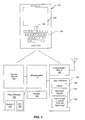
- FIG. 1 a schematic depiction of a mobile device 100 implementing an embodiment of the present technology is shown. It should be expressly understood that this figure is intentionally simplified to show only certain main components. The mobile device 100 may include other components beyond what is illustrated in FIG. 1 .
- the mobile device 100 includes a microprocessor 110 which interacts with memory 120.
- the memory 120 may be in the form of random access memory (RAM) or flash memory or both.
- the memory 120 may be in other formats such as a magnetic disk.
- the mobile device 100 includes one or more input/output devices or user interfaces 130, such as a display screen 132 (e.g. a small LCD screen or touch-sensitive display screen), and a keyboard or keypad 134.
- the user interface may also include a thumbwheel, trackball, trackpad or optical jog pad 136.
- the device may also include a USB port or serial port (not shown) for connecting to peripheral equipment.
- the mobile device 100 also includes a communication module 140 for communicating with one or more base stations (e.g. for telephone communication).
- the communication module 140 is also used to communicate with a server (e.g. 200 in FIG. 2 ) for authenticating a unique identifier of a device accessory (e.g. holster 700 in FIG. 7 and charging cradle 800 in FIG. 8).
- a server e.g. 200 in FIG. 2
- authenticating a unique identifier of a device accessory e.g. holster 700 in FIG. 7 and charging cradle 800 in FIG. 8.
- the mobile device 100 further includes a proximity detector 150.
- the short-range proximity detector 150 may also include a near-field communication (NFC) chip 152 (also referred to herein as an NFC interface) or Bluetooth® transceiver 154.
- NFC near-field communication
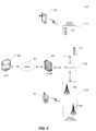
- FIG. 2 there is shown a block diagram of a communication system 200 in which an embodiment of the present technology can be applied. It should be expressly understood that this figure is intentionally simplified to show only certain main components.
- the communication system 200 may include other components beyond what is illustrated in FIG. 2 .
- the communication system 200 includes a number of mobile devices 100 which may be connected to the communication system 200 in any of several different ways. Accordingly, several instances of mobile device 100 are depicted in FIG. 2 employing different example ways of connecting to the communication system 200. Mobile device 100 is connected to the server 226 using wireless technologies. In other embodiments, mobile device 100 may use wired communication technologies.
- mobile device 100 may connect to the server 226 using wireless LAN (WLAN) 210.
- WLAN 210 may be implemented as any suitable wireless access network technology.
- WLAN 210 may be implemented using IEEE 802.11x standards (sometimes referred to as Wi-Fi) such as, for example, the IEEE 802.11a, 802.11b, 802.11g, and/or 802.11n standard.
- IEEE 802.11x standards sometimes referred to as Wi-Fi
- Other communication protocols may be used for the WLAN 210 in other example embodiments such as, for example, IEEE 802.16e (also referred to as Worldwide Interoperability for Microwave Access or "WiMAX”), or IEEE 802.20 (also referred to as Mobile Wireless Broadband Access).
- the WLAN 210 includes one or more wireless RF Access Points (AP) 212 (two of which are shown in FIG. 2 ) that collectively provide a WLAN coverage area.
- the WLAN 210 is then connected to the network gateway 220 for communication with the server 226.
- AP wireless RF Access Points
- mobile device 100 may connect to the server 226 using wireless WAN (WWAN) 230.
- WWAN wireless WAN
- the WWAN 230 may be implemented as a wireless network that includes a number of transceiver base stations 232 (two of which are shown in FIG. 2 ) where each of the base stations 232 provides wireless Radio Frequency (RF) coverage to a corresponding area or cell.
- RF Radio Frequency
- the WWAN 230 may use the following network technologies: Mobitex Radio Network, DataTAC, GSM (Global System for Mobile Communication), GPRS (General Packet Radio System), TDMA (Time Division Multiple Access), CDMA (Code Division Multiple Access), CDPD (Cellular Digital Packet Data), iDEN (integrated Digital Enhanced Network), EvDO (Evolution-Data Optimized) CDMA1010, EDGE (Enhanced Data rates for GSM Evolution), UMTS (Universal Mobile Telecommunication Systems), HSPDA (High-Speed Downlink Packet Access), IEEE 802.16e (also referred to as Worldwide Interoperability for Microwave Access or "WiMAX), or various other network technologies.
- WWAN 230 is described as a "Wide-Area" network, that term is intended herein also to incorporate wireless Metropolitan Area Networks (WMAN) and other similar technologies for providing coordinated service wirelessly over an area larger than that covered by typical WLANs.
- WMAN Wireless Metropolitan Area Networks
- mobile device 100 connects to the network gateway 220.
- the internal network 224 is typically behind a firewall 222, which serves to safeguard the internal network 224 from unauthorized access. Only authorized mobile device 100 is granted access to the server 226.
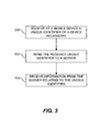
- the mobile device 100 is able to authenticate a device accessory using the communication network 200.
- the mobile device 100 receives a unique identifier of the device accessory (i.e. step 300 in FIG. 3 ).
- the mobile device 100 may use the proximity detector 150 to detect the presence of the device accessory and thereafter receive the unique identifier.
- the mobile device 100 then sends the unique identifier to a server (i.e. step 302 in FIG. 3 ) using the communication module 140.
- the mobile device 100 receives information from the server relating to the unique identifier (i.e. step 304 in FIG. 3 ).
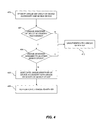
- the server 226 receives the unique identifier of the device accessory and, optionally, the unique identifier of the mobile device (i.e. step 400 in FIG. 4 ). The server 226 then confirms that the unique identifier of the device accessory is one that is recognized by the server 226 (i.e. step 402 in FIG. 4 ). The server 226 may maintain a list of one or more recognized unique identifiers in a memory. This list of one or more recognized unique identifiers may have been, for example, created by the manufacturer certifying the authenticity of a device accessory. This allows the prevention of third party accessories that may not properly follow recommended specification thereby diminishing the quality of the user experience.
- the list of one or more recognized unique identifiers may be maintained at another location such as another remote server or external storage (not shown). With this list, the server 226 compares whether the unique identifier of the device accessory received is one of the one or more recognized unique identifiers.
- the server 226 may further verify if the recognized unique identifier is associated with another mobile device (i.e. step 404 in FIG. 4 ). This ensures that a previously authenticated device accessory cannot be used by another mobile device. This may occur, for example, if the device accessory is lost or stolen. If the recognized unique identifier of the device accessory is not associated with any mobile device, the unique identifier of the mobile device 100 is associated with the recognized unique identifier of the device accessory (i.e. step 406 in FIG. 4 ). Thus, the mobile device 100 is "paired" with the device accessory.
- the determination of the server 226 is subsequently communicated to the mobile device 100, with the communication including an indication with respect to the authenticity of the device accessory.
- the indication may be that the unique identifier of the device accessory is unauthenticated (i.e. step 410 in FIG. 4 ).
- the indication may also be that the unique identifier of the device accessory is unauthenticated (i.e. step 410 in FIG. 4 ).
- the indication may be that the unique identifier of the device accessory is authorized (i.e. step 408 in FIG. 4 ).
- the feature module 160 of the mobile device 100 may enable or disable one or more functionalities of the mobile device 100 (i.e. step 406 or 408 in FIG. 4 ).
- the mobile device 100 may enable or disable all of the functionalities of the mobile device 100.
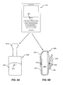
- the mobile device 100 may enable or disable one or more functionalities specific to the type of the device accessory. For example, where the device accessory is a holster (e.g. 600 of FIGs. 6A and 6B ), one functionality may be sleep-in-holster to conserve battery. Another functionality may be auto switching of device profile to silent mode.
- the received unique identifier of the device accessory may be stored in memory 120 of the mobile device 100.
- the received information from the server such as authentication information, may be stored in the memory 120 of the mobile device 100.
- the mobile device receives a unique identifier of the device accessory (i.e. 502 in FIG. 5 ).
- the mobile device 100 may detect the presence of the device accessory (i.e. 500 in FIG. 5 ) using the proximity detector (e.g. 150 of FIG. 1 ).
- the mobile device sends the unique identifier to the server (i.e. 504 in FIG. 5 ).
- the mobile device may send its unique identifier, if assigned, to the server along with the received unique identifier of the device accessory.
- the server processes the unique identifier sent by the mobile device 100, the mobile device receives information relating to the unique identifier from the server (i.e. 506 in FIG. 5 ).
- a swivel mount for GPS for GPS
- vehicle mount for GPS
- speaker stand for GPS
- headset for GPS
- headset for navigation
- docking station for navigation
- hands-free device for navigation
- other device accessories such as, but not limited to, a swivel mount for GPS, vehicle mount, a speaker stand, a headset, a docking station, a hands-free device and other device accessories.
- the holster 600 has a housing 602 defining a pocket 604. On the backside of the housing 602, there is a backplate 606 with a clip 608.
- the holster 600 shown also has an over-clip 610 for securing the mobile device 100 inserted into the pocket 604.
- the holster 600 may include a magnet 612, which works in conjunction with the hall sensor 620 embedded in the mobile device 100. This allows the mobile device 100 to detect when it is placed in the pocket 604 of the housing 602 to place the mobile device 100 into, for example, sleep-in-holster mode. As a result, the mobile device 100 is able to conserve battery life. This may be one of the many functions of the mobile device 100 enabled by the holster 600.
- the holster 600 implementing an embodiment of the present technology includes a wireless interface 614 including the unique identifier of the device accessory.
- the holster 600 is first authenticated by the mobile device 100 which implements an embodiment of the present technology.
- the mobile device 100 first detects the proximity of the holster 600 using a proximity detector (e.g. 150 in FIG. 1 ) of the mobile device 100.
- the mobile device 100 receives the unique identifier of the holster 600 from the wireless interface 614 and sends the unique identifier to the server (e.g. 226 in FIG. 2 ).
- the mobile device 100 also sends a unique identifier assigned to the mobile device 100 along with the unique identifier received from the holster 600.
- the server determines whether the unique identifier of the holster 600 is a recognized unique identifier. If the unique identifier of the holster 600 is a recognized unique identifier, the server further determines if the unique identifier has been previously assigned to another mobile device. If not, the unique identifier of the holster 600 is associated with the unique identifier of the mobile device 100 and the server indicates to the mobile device 100 that the unique identifier of the holster 600 is authenticated. Otherwise (i.e. unique identifier of the holster 600 is not recognized or assigned to another device), the server indicates that the unique identifier of the holster 600 is unauthenticated. Furthermore, the mobile device 100 may receive information relating to the type of the device accessory, in this case a holster, along with the received information relating to the authenticity of the unique identifier.
- some or all of the functionalities of the mobile device 100 may be disabled.
- the sleep-in-holster functionality mentioned above may be disabled. So, while the holster 600 may still be used to hold the mobile device 100, convenient features such as the sleep-in-holster functionality may be disabled.
- the mobile device 100 may have a feature to automatically switch the alert profile of the mobile device 100, which may be disabled for unauthenticated holster 600.
- the mobile device 100 may automatically switch into silent mode when the mobile device 100 detects the magnet 612. Additional functionalities of the mobile device 100 may be enabled and disabled with the present technology.
- the mobile device 100 may store the unique identifier of the authenticated holster 600 in a memory of the mobile device 100 (e.g. 120 in FIG. 1 ) for later retrieval. Subsequently, when the mobile device 100 is used again with the holster 600, the mobile device 100 checks in the memory to verify that the holster 600 had been previously authenticated. If previously authenticated, the mobile device 100 may only re-authenticate the holster 600 if a predetermined amount of time has elapsed since the last authentication. Alternatively, re-authentication may take place each time.
- the charging cradle 700 includes a cradle body 702 defining a receiving area 704 for receiving a mobile device 100. While the primary purpose of the charging cradle 700 may be for charging the mobile device 100, the charging cradle 700 may provide other functionalities such as connection to external speakers, data synchronization and other features.
- the charging cradle 700 is first authenticated by the mobile device 100 which implements an embodiment of the present technology.
- the mobile device 100 is brought within proximity of the charging cradle 700.
- the proximity detector of the mobile device 100 receives the unique identifier of the charging cradle 700 from the wireless interface 706.
- the unique identifier of the charging cradle 700 then sends the unique identifier to the server (e.g. 226 in FIG. 2 ).
- the sending of the unique identifier to the server may be auto-initiated by mobile device 100 upon detection of the wireless interface 706. Alternatively, or additionally, it may be initiated by a user of the mobile device 100 using a user interface.
- the server When the server receives the unique identifier of the charging cradle 700, it confirms that the unique identifier is indeed a recognized unique identifier. This may be achieved by the server maintaining a list of recognized unique identifier and checking the unique identifier of the charging cradle 700 against this list. Other implementations are possible such as verifying that the unique identifier of the charging cradle 700 conforms to a predetermined algorithm. Once the server determines that the unique identifier of the charging cradle 700 is a recognized identifier, the result is communicated to the mobile device 100. In this implementation, where the unique identifier is recognized, the server indicates that the unique identifier is authenticated. By contrast, if the unique identifier of the charging cradle 700 is not recognized, the server indicates that the unique identifier is unauthenticated.
- the mobile device 100 may additionally send a unique identifier of the mobile device 100 with the unique identifier of the charging cradle 700.
- the server may also verify that the unique identifier of the charging cradle 700 was not previously assigned to another mobile device. This ensures that a previously authorized unique identifier cannot be paired with another mobile device.
- the charging cradle 700 may trigger the mobile device 100 to automatically enable speakerphone to permit voice communication while the mobile device 100 is still in the charging cradle 700.
- Other functionalities such as auto call-forwarding to a home line may be possible.
- the mobile device 100 may store the unique identifier of the authenticated charging cradle 700 in a memory of the mobile device 100 (e.g. 120 in FIG. 1 ) for later retrieval. Subsequently, when the mobile device 100 is used again with the charging cradle 700, the mobile device 100 checks in the memory to verify that the charging cradle 700 had been previously authenticated. If previously authenticated, the mobile device 100 may only re-authenticate the charging cradle 700 if a predetermined amount of time has elapsed since the last authentication. Alternatively, re-authentication may take place each time.
Landscapes
- Engineering & Computer Science (AREA)
- Computer Security & Cryptography (AREA)
- Computer Networks & Wireless Communication (AREA)
- Signal Processing (AREA)
- Computer Hardware Design (AREA)
- Computing Systems (AREA)
- General Engineering & Computer Science (AREA)
- Telephone Function (AREA)
- Mobile Radio Communication Systems (AREA)
Abstract
Description
- The present disclosure relates to a mobile device and, in particular, to a mobile device for authenticating a device accessory.
- With the increase in popularity of mobile devices, consumer appetite for device accessories have increased dramatically over the years. Device accessories may range from providing essential functionalities, such as charging a battery, to non-essential features, such as enabling hands-free communication. Because of this popularity, there are many third party companies developing device accessories for use with mobile devices. However, one of the shortcomings of third party device accessories is that quality of such accessories cannot be controlled by the manufacturers of the mobile devices. Thus, user experience of the device accessory and the mobile device may be diminished.
- A mobile device that is able to authenticate a device accessory would thus be highly desirable.
- According to an aspect of the present technology, a method entails receiving at a mobile device a unique identifier from a device accessory, sending the received unique identifier to a server via a communication network, and receiving information from the server relating to the unique identifier.
- Another aspect of the present technology is a computer readable storage medium upon which are stored instructions in code that are configured to perform the steps of the foregoing method when the computer readable medium is loaded into memory and executed on a processor of a mobile device.
- According to a further aspect of the present technology, a mobile device for authenticating a device accessory is disclosed. The mobile device includes a proximity detector, a communication module for communicating with a server to authenticate a unique identifier of the device accessory, and a feature module for enabling and disabling functionality of the mobile device.
- These and other features of the disclosure will become more apparent from the following description in which reference is made to the appended drawings wherein:
-
FIG. 1 is a schematic depiction of a mobile device on which the present technology can be implemented; -
FIG. 2 is a block diagram of a communication system in which an embodiment of the present technology may be applied; -
FIG. 3 is a flowchart outlining the main steps of the mobile device ofFIG. 1 for authenticating a device accessory; -
FIG. 4 is a flowchart outlining the main steps of the server ofFIG. 2 for authenticating a device accessory; -
FIG. 5 is a messaging diagram of the message flow between the mobile device, device accessory and the server; -
FIG. 6A is a front view of a holster for authentication with the mobile device ofFIG. 1 ; -
FIG. 6B is a side view of the holster inFIG. 6A ; and -
FIG. 7 is a perspective view of a charging cradle for authentication with the mobile device ofFIG. 1 . - While the patent disclosure is described in conjunction with the specific embodiments, it will be understood that it is not intended to limit the patent disclosure to the described embodiments. On the contrary, it is intended to cover alternatives, modifications, and equivalents as may be included within the scope of the patent disclosure as defined by the appended claims. In the above description, numerous specific details are set forth in order to provide a thorough understanding of the present patent disclosure. The present patent disclosure may be practiced without some or all of these specific details.
- In this specification and the appended claims, the singular forms "a," "an," and "the" include plural references unless the context clearly dictates otherwise. Unless defined otherwise, all technical and scientific terms used herein have the same meaning as commonly understood to one of ordinary skill in the art to which this disclosure belongs.
- It will be further understood that the terms "comprises" or "comprising", or both when used in this specification, specify the presence of stated features, integers, steps, operations, elements, and/or components, but do not preclude the presence or addition of one or more other features, integers, steps, operations, elements, components, and/or groups thereof.
- Referring to
FIG. 1 , a schematic depiction of amobile device 100 implementing an embodiment of the present technology is shown. It should be expressly understood that this figure is intentionally simplified to show only certain main components. Themobile device 100 may include other components beyond what is illustrated inFIG. 1 . - As shown in
FIG. 1 , themobile device 100 includes amicroprocessor 110 which interacts withmemory 120. Thememory 120 may be in the form of random access memory (RAM) or flash memory or both. Thememory 120 may be in other formats such as a magnetic disk. Themobile device 100 includes one or more input/output devices oruser interfaces 130, such as a display screen 132 (e.g. a small LCD screen or touch-sensitive display screen), and a keyboard orkeypad 134. The user interface may also include a thumbwheel, trackball, trackpad oroptical jog pad 136. The device may also include a USB port or serial port (not shown) for connecting to peripheral equipment. - The
mobile device 100 also includes acommunication module 140 for communicating with one or more base stations (e.g. for telephone communication). Thecommunication module 140 is also used to communicate with a server (e.g. 200 inFIG. 2 ) for authenticating a unique identifier of a device accessory (e.g. holster 700 inFIG. 7 and charging cradle 800 in FIG. 8). - The
mobile device 100 further includes aproximity detector 150. The short-range proximity detector 150 may also include a near-field communication (NFC) chip 152 (also referred to herein as an NFC interface) or Bluetooth® transceiver 154. - Now turning to
FIG. 2 , there is shown a block diagram of acommunication system 200 in which an embodiment of the present technology can be applied. It should be expressly understood that this figure is intentionally simplified to show only certain main components. Thecommunication system 200 may include other components beyond what is illustrated inFIG. 2 . - The
communication system 200 includes a number ofmobile devices 100 which may be connected to thecommunication system 200 in any of several different ways. Accordingly, several instances ofmobile device 100 are depicted inFIG. 2 employing different example ways of connecting to thecommunication system 200.Mobile device 100 is connected to theserver 226 using wireless technologies. In other embodiments,mobile device 100 may use wired communication technologies. - In one embodiment,
mobile device 100 may connect to theserver 226 using wireless LAN (WLAN) 210. WLAN 210 may be implemented as any suitable wireless access network technology. By way of example, but not limitation, WLAN 210 may be implemented using IEEE 802.11x standards (sometimes referred to as Wi-Fi) such as, for example, the IEEE 802.11a, 802.11b, 802.11g, and/or 802.11n standard. Other communication protocols may be used for the WLAN 210 in other example embodiments such as, for example, IEEE 802.16e (also referred to as Worldwide Interoperability for Microwave Access or "WiMAX"), or IEEE 802.20 (also referred to as Mobile Wireless Broadband Access). - The WLAN 210 includes one or more wireless RF Access Points (AP) 212 (two of which are shown in
FIG. 2 ) that collectively provide a WLAN coverage area. The WLAN 210 is then connected to thenetwork gateway 220 for communication with theserver 226. - In another embodiment,
mobile device 100 may connect to theserver 226 using wireless WAN (WWAN) 230. By way of example, but not limitation, the WWAN 230 may be implemented as a wireless network that includes a number of transceiver base stations 232 (two of which are shown inFIG. 2 ) where each of thebase stations 232 provides wireless Radio Frequency (RF) coverage to a corresponding area or cell. In some example embodiments, the WWAN 230 may use the following network technologies: Mobitex Radio Network, DataTAC, GSM (Global System for Mobile Communication), GPRS (General Packet Radio System), TDMA (Time Division Multiple Access), CDMA (Code Division Multiple Access), CDPD (Cellular Digital Packet Data), iDEN (integrated Digital Enhanced Network), EvDO (Evolution-Data Optimized) CDMA1010, EDGE (Enhanced Data rates for GSM Evolution), UMTS (Universal Mobile Telecommunication Systems), HSPDA (High-Speed Downlink Packet Access), IEEE 802.16e (also referred to as Worldwide Interoperability for Microwave Access or "WiMAX), or various other network technologies. Although WWAN 230 is described as a "Wide-Area" network, that term is intended herein also to incorporate wireless Metropolitan Area Networks (WMAN) and other similar technologies for providing coordinated service wirelessly over an area larger than that covered by typical WLANs. - Using wireless or wired technologies,
mobile device 100 connects to thenetwork gateway 220. Theinternal network 224 is typically behind afirewall 222, which serves to safeguard theinternal network 224 from unauthorized access. Only authorizedmobile device 100 is granted access to theserver 226. - Thus, the
mobile device 100 is able to authenticate a device accessory using thecommunication network 200. Now referring to bothFIGs. 1 and3 , themobile device 100 receives a unique identifier of the device accessory (i.e.step 300 inFIG. 3 ). In one embodiment, themobile device 100 may use theproximity detector 150 to detect the presence of the device accessory and thereafter receive the unique identifier. Themobile device 100 then sends the unique identifier to a server (i.e.step 302 inFIG. 3 ) using thecommunication module 140. After processing, themobile device 100 receives information from the server relating to the unique identifier (i.e.step 304 inFIG. 3 ). - Now referring to
FIG. 4 , theserver 226 receives the unique identifier of the device accessory and, optionally, the unique identifier of the mobile device (i.e.step 400 inFIG. 4 ). Theserver 226 then confirms that the unique identifier of the device accessory is one that is recognized by the server 226 (i.e.step 402 inFIG. 4 ). Theserver 226 may maintain a list of one or more recognized unique identifiers in a memory. This list of one or more recognized unique identifiers may have been, for example, created by the manufacturer certifying the authenticity of a device accessory. This allows the prevention of third party accessories that may not properly follow recommended specification thereby diminishing the quality of the user experience. Alternatively, or additionally, the list of one or more recognized unique identifiers may be maintained at another location such as another remote server or external storage (not shown). With this list, theserver 226 compares whether the unique identifier of the device accessory received is one of the one or more recognized unique identifiers. - If the unique identifier of the device accessory is one that is recognized by the
server 226, theserver 226 may further verify if the recognized unique identifier is associated with another mobile device (i.e.step 404 inFIG. 4 ). This ensures that a previously authenticated device accessory cannot be used by another mobile device. This may occur, for example, if the device accessory is lost or stolen. If the recognized unique identifier of the device accessory is not associated with any mobile device, the unique identifier of themobile device 100 is associated with the recognized unique identifier of the device accessory (i.e.step 406 inFIG. 4 ). Thus, themobile device 100 is "paired" with the device accessory. - The determination of the
server 226 is subsequently communicated to themobile device 100, with the communication including an indication with respect to the authenticity of the device accessory. In one implementation, if the unique identifier of the device accessory is not recognized by theserver 226, the indication may be that the unique identifier of the device accessory is unauthenticated (i.e.step 410 inFIG. 4 ). Moreover, if the unique identifier of the device accessory is recognized but already assigned to a unique identifier of another mobile device, the indication may also be that the unique identifier of the device accessory is unauthenticated (i.e.step 410 inFIG. 4 ). However, if the unique identifier is recognized and not associated with a unique identifier of another mobile device, the indication may be that the unique identifier of the device accessory is authorized (i.e.step 408 inFIG. 4 ). - Based on the communication from the
server 226, thefeature module 160 of themobile device 100 may enable or disable one or more functionalities of the mobile device 100 (i.e.step FIG. 4 ). In one embodiment, themobile device 100 may enable or disable all of the functionalities of themobile device 100. In other embodiments, if themobile device 100 receives an indication relating to the type of the device accessory, themobile device 100 may enable or disable one or more functionalities specific to the type of the device accessory. For example, where the device accessory is a holster (e.g. 600 ofFIGs. 6A and 6B ), one functionality may be sleep-in-holster to conserve battery. Another functionality may be auto switching of device profile to silent mode. - In another embodiment, the received unique identifier of the device accessory may be stored in
memory 120 of themobile device 100. In a further embodiment, the received information from the server, such as authentication information, may be stored in thememory 120 of themobile device 100. - Turning to
FIG. 5 , a message exchange diagram between the mobile device, device accessory and server is shown. To authenticate the device accessory, the mobile device receives a unique identifier of the device accessory (i.e. 502 inFIG. 5 ). In another embodiment, prior to receiving the unique identifier, themobile device 100 may detect the presence of the device accessory (i.e. 500 inFIG. 5 ) using the proximity detector (e.g. 150 ofFIG. 1 ). After receiving the unique identifier from the accessory, the mobile device sends the unique identifier to the server (i.e. 504 inFIG. 5 ). Additionally, the mobile device may send its unique identifier, if assigned, to the server along with the received unique identifier of the device accessory. After the server processes the unique identifier sent by themobile device 100, the mobile device receives information relating to the unique identifier from the server (i.e. 506 inFIG. 5 ). - Specific implementations involving a holster and charging cradle using NFC tags will now be described below. While not specifically described in this disclosure, the present technology may be implemented in other device accessories such as, but not limited to, a swivel mount for GPS, vehicle mount, a speaker stand, a headset, a docking station, a hands-free device and other device accessories.
- In
FIGs. 6A and 6B , there is shown an implementation of the present technology. In this implementation, theholster 600 has ahousing 602 defining apocket 604. On the backside of thehousing 602, there is abackplate 606 with aclip 608. Theholster 600 shown also has anover-clip 610 for securing themobile device 100 inserted into thepocket 604. Theholster 600 may include amagnet 612, which works in conjunction with thehall sensor 620 embedded in themobile device 100. This allows themobile device 100 to detect when it is placed in thepocket 604 of thehousing 602 to place themobile device 100 into, for example, sleep-in-holster mode. As a result, themobile device 100 is able to conserve battery life. This may be one of the many functions of themobile device 100 enabled by theholster 600. - The
holster 600 implementing an embodiment of the present technology includes awireless interface 614 including the unique identifier of the device accessory. Prior to use, theholster 600 is first authenticated by themobile device 100 which implements an embodiment of the present technology. In this particular embodiment, themobile device 100 first detects the proximity of theholster 600 using a proximity detector (e.g. 150 inFIG. 1 ) of themobile device 100. Themobile device 100 then receives the unique identifier of theholster 600 from thewireless interface 614 and sends the unique identifier to the server (e.g. 226 inFIG. 2 ). In this implementation, themobile device 100 also sends a unique identifier assigned to themobile device 100 along with the unique identifier received from theholster 600. The server then determines whether the unique identifier of theholster 600 is a recognized unique identifier. If the unique identifier of theholster 600 is a recognized unique identifier, the server further determines if the unique identifier has been previously assigned to another mobile device. If not, the unique identifier of theholster 600 is associated with the unique identifier of themobile device 100 and the server indicates to themobile device 100 that the unique identifier of theholster 600 is authenticated. Otherwise (i.e. unique identifier of theholster 600 is not recognized or assigned to another device), the server indicates that the unique identifier of theholster 600 is unauthenticated. Furthermore, themobile device 100 may receive information relating to the type of the device accessory, in this case a holster, along with the received information relating to the authenticity of the unique identifier. - For
unauthenticated holster 600, some or all of the functionalities of themobile device 100 may be disabled. For example, the sleep-in-holster functionality mentioned above may be disabled. So, while theholster 600 may still be used to hold themobile device 100, convenient features such as the sleep-in-holster functionality may be disabled. As a further example, themobile device 100 may have a feature to automatically switch the alert profile of themobile device 100, which may be disabled forunauthenticated holster 600. - For authenticated
holster 600, themobile device 100 may automatically switch into silent mode when themobile device 100 detects themagnet 612. Additional functionalities of themobile device 100 may be enabled and disabled with the present technology. - Upon authentication, the
mobile device 100 may store the unique identifier of the authenticatedholster 600 in a memory of the mobile device 100 (e.g. 120 inFIG. 1 ) for later retrieval. Subsequently, when themobile device 100 is used again with theholster 600, themobile device 100 checks in the memory to verify that theholster 600 had been previously authenticated. If previously authenticated, themobile device 100 may only re-authenticate theholster 600 if a predetermined amount of time has elapsed since the last authentication. Alternatively, re-authentication may take place each time. - In
FIG. 7 , there is shown another implementation of the present technology. The chargingcradle 700 includes acradle body 702 defining a receivingarea 704 for receiving amobile device 100. While the primary purpose of the chargingcradle 700 may be for charging themobile device 100, the chargingcradle 700 may provide other functionalities such as connection to external speakers, data synchronization and other features. - Where the charging
cradle 700 includes awireless interface 706 including the unique identifier of the chargingcradle 700, the chargingcradle 700 is first authenticated by themobile device 100 which implements an embodiment of the present technology. In this particular embodiment, to authenticate the chargingcradle 700, themobile device 100 is brought within proximity of the chargingcradle 700. The proximity detector of themobile device 100 then receives the unique identifier of the chargingcradle 700 from thewireless interface 706. The unique identifier of the chargingcradle 700 then sends the unique identifier to the server (e.g. 226 inFIG. 2 ). The sending of the unique identifier to the server may be auto-initiated bymobile device 100 upon detection of thewireless interface 706. Alternatively, or additionally, it may be initiated by a user of themobile device 100 using a user interface. - When the server receives the unique identifier of the charging
cradle 700, it confirms that the unique identifier is indeed a recognized unique identifier. This may be achieved by the server maintaining a list of recognized unique identifier and checking the unique identifier of the chargingcradle 700 against this list. Other implementations are possible such as verifying that the unique identifier of the chargingcradle 700 conforms to a predetermined algorithm. Once the server determines that the unique identifier of the chargingcradle 700 is a recognized identifier, the result is communicated to themobile device 100. In this implementation, where the unique identifier is recognized, the server indicates that the unique identifier is authenticated. By contrast, if the unique identifier of the chargingcradle 700 is not recognized, the server indicates that the unique identifier is unauthenticated. - As an added security measure, the
mobile device 100 may additionally send a unique identifier of themobile device 100 with the unique identifier of the chargingcradle 700. Thus, in addition to the server determining whether the unique identifier of the chargingcradle 700 is recognized, it may also verify that the unique identifier of the chargingcradle 700 was not previously assigned to another mobile device. This ensures that a previously authorized unique identifier cannot be paired with another mobile device. - For authenticated charging
cradle 700, various functionalities of themobile device 100 may be enabled. For example, the chargingcradle 700 may trigger themobile device 100 to automatically enable speakerphone to permit voice communication while themobile device 100 is still in the chargingcradle 700. Other functionalities such as auto call-forwarding to a home line may be possible. - Upon authentication, the
mobile device 100 may store the unique identifier of the authenticated chargingcradle 700 in a memory of the mobile device 100 (e.g. 120 inFIG. 1 ) for later retrieval. Subsequently, when themobile device 100 is used again with the chargingcradle 700, themobile device 100 checks in the memory to verify that the chargingcradle 700 had been previously authenticated. If previously authenticated, themobile device 100 may only re-authenticate the chargingcradle 700 if a predetermined amount of time has elapsed since the last authentication. Alternatively, re-authentication may take place each time. - While the present technology has been described in terms of specific implementations and configurations, further modifications, variations, modifications and refinements may be made without departing from the inventive concepts presented herein. For example, while the mobile device implementing the present technology was only described with a charging cradle and a holster, other device accessories are possible such as a swivel mount for GPS, vehicle mount, a speaker stand, a headset, a docking station, a hands-free device and other device accessories without departing from the scope of the disclosure as defined in the claims. The scope of the exclusive right sought by the Applicant(s) is therefore intended to be limited solely by the appended claims.
Claims (15)
- A method comprising:receiving at a mobile device a unique identifier from a device accessory (300);sending the received unique identifier to a server via a communication network (302); andreceiving information from the server relating to the unique identifier (304).
- The method according to claim 1, further comprising:detecting a proximity of the device accessory using a proximity detector of the mobile device.
- The method according to claim 1 or claim 2, wherein the received information from the server comprises:an indication of authenticity of the unique identifier comprising that the device accessory is authenticated or unauthenticated, wherein the authenticated device accessory having a unique identifier recognized by the server, and the unauthenticated device accessory having a unique identifier unrecognized by the server.
- The method according to any preceding claim, further comprising sending a unique mobile device identifier to the server with the unique identifier.
- The method according to claim 4, wherein the received information from the server comprises:an indication of authenticity of the unique identifier comprising that the device accessory is authenticated or unauthenticated, wherein the authenticated device accessory having a unique identifier recognized by the server and not associated with another mobile device, and the unauthenticated device accessory having a unique identifier unrecognized by the server or associated with another mobile device.
- The method according to any preceding claim, further comprising:receiving information from the server indicating a type of the device accessory.
- The method according to claim 6, wherein the type of the device accessory comprises a holster, a charger, a docking station, a swivel mount for GPS, a vehicle mount, a speaker stand, a headset, or a hands-free device.
- The method according to any preceding claim, further comprising either enabling or disabling a functionality of the mobile device.
- The method according to any of claims 6 to 8, further comprising either enabling or disabling a functionality of the mobile device associated to the type of the device accessory.
- The method according to any preceding claim, further comprising:storing the unique identifier in a memory of the mobile device.
- The method according to any preceding claim, further comprising:storing the received information from the server in a memory of the mobile device.
- A mobile device for authenticating a device accessory, the mobile device comprising:a proximity detector (150);a communication module (140) for communicating with a server (226) to authenticate a unique identifier of the device accessory; anda feature module (160) for enabling and disabling a functionality of the mobile device.
- The mobile device according to claim 12, wherein for the authenticated mobile device accessory, the feature module enables the functionality of the mobile device and for the unauthenticated mobile device, the feature module disables the functionality of the mobile device.
- The mobile device according to claim 12 or claim 13, wherein the functionality of the mobile device is associated to a type of the device accessory.
- A computer-readable storage medium comprising instructions in code which when loaded into a memory and executed by a processor of a mobile device causes the mobile device to:receive at a mobile device a unique identifier from a device accessory (300);send the received unique identifier to a server via a communication network (302); andreceive information from the server relating to the unique identifier (304).
Priority Applications (2)
| Application Number | Priority Date | Filing Date | Title |
|---|---|---|---|
| EP10196881.6A EP2469902B1 (en) | 2010-12-23 | 2010-12-23 | Mobile device for authenticating a device accessory |
| CA2762550A CA2762550C (en) | 2010-12-23 | 2011-12-20 | Mobile device for authenticating a device accessory |
Applications Claiming Priority (1)
| Application Number | Priority Date | Filing Date | Title |
|---|---|---|---|
| EP10196881.6A EP2469902B1 (en) | 2010-12-23 | 2010-12-23 | Mobile device for authenticating a device accessory |
Publications (2)
| Publication Number | Publication Date |
|---|---|
| EP2469902A1 true EP2469902A1 (en) | 2012-06-27 |
| EP2469902B1 EP2469902B1 (en) | 2015-12-16 |
Family
ID=43901830
Family Applications (1)
| Application Number | Title | Priority Date | Filing Date |
|---|---|---|---|
| EP10196881.6A Active EP2469902B1 (en) | 2010-12-23 | 2010-12-23 | Mobile device for authenticating a device accessory |
Country Status (2)
| Country | Link |
|---|---|
| EP (1) | EP2469902B1 (en) |
| CA (1) | CA2762550C (en) |
Cited By (2)
| Publication number | Priority date | Publication date | Assignee | Title |
|---|---|---|---|---|
| WO2014120695A1 (en) * | 2013-02-01 | 2014-08-07 | Microsoft Corporation | Securing a computing device accessory |
| US12407512B2 (en) | 2022-12-21 | 2025-09-02 | Microsoft Technology Licensing, Llc | Securing a computing device accessory |
Citations (4)
| Publication number | Priority date | Publication date | Assignee | Title |
|---|---|---|---|---|
| US20040034579A1 (en) * | 2002-08-19 | 2004-02-19 | Xu Jerry Zhi | Combining the internet and bar code technologies, using random identification numbers to prevent counterfeit products |
| US20040155106A1 (en) * | 2002-11-15 | 2004-08-12 | Schmidtberg Rupert A. | Methods and apparatus for communicating condition information associated with an item |
| US20060071778A1 (en) * | 2004-09-27 | 2006-04-06 | Nokia Corporation | Methods, systems, devices and computer program products for providing dynamic product information in short-range communication |
| JP2010061490A (en) * | 2008-09-05 | 2010-03-18 | Nec Electronics Corp | Accessory authentication system, accessory authentication method, and management server |
-
2010
- 2010-12-23 EP EP10196881.6A patent/EP2469902B1/en active Active
-
2011
- 2011-12-20 CA CA2762550A patent/CA2762550C/en active Active
Patent Citations (4)
| Publication number | Priority date | Publication date | Assignee | Title |
|---|---|---|---|---|
| US20040034579A1 (en) * | 2002-08-19 | 2004-02-19 | Xu Jerry Zhi | Combining the internet and bar code technologies, using random identification numbers to prevent counterfeit products |
| US20040155106A1 (en) * | 2002-11-15 | 2004-08-12 | Schmidtberg Rupert A. | Methods and apparatus for communicating condition information associated with an item |
| US20060071778A1 (en) * | 2004-09-27 | 2006-04-06 | Nokia Corporation | Methods, systems, devices and computer program products for providing dynamic product information in short-range communication |
| JP2010061490A (en) * | 2008-09-05 | 2010-03-18 | Nec Electronics Corp | Accessory authentication system, accessory authentication method, and management server |
Cited By (5)
| Publication number | Priority date | Publication date | Assignee | Title |
|---|---|---|---|---|
| WO2014120695A1 (en) * | 2013-02-01 | 2014-08-07 | Microsoft Corporation | Securing a computing device accessory |
| US9124434B2 (en) | 2013-02-01 | 2015-09-01 | Microsoft Technology Licensing, Llc | Securing a computing device accessory |
| US9660815B2 (en) | 2013-02-01 | 2017-05-23 | Microsoft Technology Licensing, Llc | Securing a computing device accessory |
| US9948636B2 (en) | 2013-02-01 | 2018-04-17 | Microsoft Technology Licensing, Llc | Securing a computing device accessory |
| US12407512B2 (en) | 2022-12-21 | 2025-09-02 | Microsoft Technology Licensing, Llc | Securing a computing device accessory |
Also Published As
| Publication number | Publication date |
|---|---|
| CA2762550A1 (en) | 2012-06-23 |
| EP2469902B1 (en) | 2015-12-16 |
| CA2762550C (en) | 2016-12-13 |
Similar Documents
| Publication | Publication Date | Title |
|---|---|---|
| US9135429B2 (en) | Mobile device for authenticating a device accessory | |
| EP2594056B1 (en) | Securing a mobile computing device | |
| EP2533506B1 (en) | Communications system providing enhanced mobile device holder detection based upon nfc communication and related methods | |
| US9215659B2 (en) | Method and apparatus for disconnecting a wireless communication link between a communication device and a mobile device | |
| US8271050B2 (en) | Automatic in-vehicle mobile device detection | |
| US8805281B2 (en) | Controlling device functions of a mobile terminal in a restricted area | |
| US9262604B2 (en) | Method and system for locking an electronic device | |
| US20120302170A1 (en) | Method and apparatus for performing role management of short-range wireless connections | |
| US9007174B2 (en) | Service identification authentication | |
| US8639290B2 (en) | UICC control over devices used to obtain service | |
| US9516529B2 (en) | Method and device to prohibit communications which require active participation by the driver of a vehicle | |
| US20080220741A1 (en) | Mobile device, communication system, and connection establishing method | |
| US20140200053A1 (en) | Advanced thermal control algorithm | |
| US20080013601A1 (en) | Method and Device for Bluetooth Pairing | |
| EP3025450A1 (en) | Methods for authenticating device-to-device communication | |
| CN105025490A (en) | A method and device for identifying a pseudo-base station | |
| JP2007507129A (en) | Method, electronic device and computer program product for transmitting data stored in electronic device in the absence of subscriber verification module | |
| US7224937B2 (en) | Mobile station apparatus capable of changing access control classes due to low battery condition for power saving and method of the same | |
| CN101828413B (en) | Mobile phone location and data security | |
| CA2762550C (en) | Mobile device for authenticating a device accessory | |
| US20180322273A1 (en) | Method and apparatus for limited starting authorization | |
| EP2173120B1 (en) | Method for remotely controlling portable terminal and system therefor | |
| CN102420852B (en) | Server, mobile terminal and data synchronizing method | |
| JP2004120693A (en) | Radio communication apparatus, radio communication system, radio communication method, and radio communication program | |
| CN102447763A (en) | bluetooth headset for mobile phone |
Legal Events
| Date | Code | Title | Description |
|---|---|---|---|
| 17P | Request for examination filed |
Effective date: 20101223 |
|
| AK | Designated contracting states |
Kind code of ref document: A1 Designated state(s): AL AT BE BG CH CY CZ DE DK EE ES FI FR GB GR HR HU IE IS IT LI LT LU LV MC MK MT NL NO PL PT RO RS SE SI SK SM TR |
|
| AX | Request for extension of the european patent |
Extension state: BA ME |
|
| PUAI | Public reference made under article 153(3) epc to a published international application that has entered the european phase |
Free format text: ORIGINAL CODE: 0009012 |
|
| 17Q | First examination report despatched |
Effective date: 20130624 |
|
| RAP1 | Party data changed (applicant data changed or rights of an application transferred) |
Owner name: BLACKBERRY LIMITED |
|
| RAP1 | Party data changed (applicant data changed or rights of an application transferred) |
Owner name: BLACKBERRY LIMITED |
|
| GRAP | Despatch of communication of intention to grant a patent |
Free format text: ORIGINAL CODE: EPIDOSNIGR1 |
|
| INTG | Intention to grant announced |
Effective date: 20150624 |
|
| GRAS | Grant fee paid |
Free format text: ORIGINAL CODE: EPIDOSNIGR3 |
|
| GRAA | (expected) grant |
Free format text: ORIGINAL CODE: 0009210 |
|
| AK | Designated contracting states |
Kind code of ref document: B1 Designated state(s): AL AT BE BG CH CY CZ DE DK EE ES FI FR GB GR HR HU IE IS IT LI LT LU LV MC MK MT NL NO PL PT RO RS SE SI SK SM TR |
|
| REG | Reference to a national code |
Ref country code: GB Ref legal event code: FG4D |
|
| REG | Reference to a national code |
Ref country code: FR Ref legal event code: PLFP Year of fee payment: 6 |
|
| REG | Reference to a national code |
Ref country code: CH Ref legal event code: EP |
|
| REG | Reference to a national code |
Ref country code: IE Ref legal event code: FG4D |
|
| REG | Reference to a national code |
Ref country code: AT Ref legal event code: REF Ref document number: 766062 Country of ref document: AT Kind code of ref document: T Effective date: 20160115 |
|
| REG | Reference to a national code |
Ref country code: DE Ref legal event code: R096 Ref document number: 602010029481 Country of ref document: DE |
|
| REG | Reference to a national code |
Ref country code: NL Ref legal event code: MP Effective date: 20151216 |
|
| REG | Reference to a national code |
Ref country code: LT Ref legal event code: MG4D |
|
| PG25 | Lapsed in a contracting state [announced via postgrant information from national office to epo] |
Ref country code: LT Free format text: LAPSE BECAUSE OF FAILURE TO SUBMIT A TRANSLATION OF THE DESCRIPTION OR TO PAY THE FEE WITHIN THE PRESCRIBED TIME-LIMIT Effective date: 20151216 Ref country code: HR Free format text: LAPSE BECAUSE OF FAILURE TO SUBMIT A TRANSLATION OF THE DESCRIPTION OR TO PAY THE FEE WITHIN THE PRESCRIBED TIME-LIMIT Effective date: 20151216 Ref country code: NO Free format text: LAPSE BECAUSE OF FAILURE TO SUBMIT A TRANSLATION OF THE DESCRIPTION OR TO PAY THE FEE WITHIN THE PRESCRIBED TIME-LIMIT Effective date: 20160316 |
|
| REG | Reference to a national code |
Ref country code: AT Ref legal event code: MK05 Ref document number: 766062 Country of ref document: AT Kind code of ref document: T Effective date: 20151216 |
|
| PG25 | Lapsed in a contracting state [announced via postgrant information from national office to epo] |
Ref country code: LV Free format text: LAPSE BECAUSE OF FAILURE TO SUBMIT A TRANSLATION OF THE DESCRIPTION OR TO PAY THE FEE WITHIN THE PRESCRIBED TIME-LIMIT Effective date: 20151216 Ref country code: BE Free format text: LAPSE BECAUSE OF NON-PAYMENT OF DUE FEES Effective date: 20151231 Ref country code: FI Free format text: LAPSE BECAUSE OF FAILURE TO SUBMIT A TRANSLATION OF THE DESCRIPTION OR TO PAY THE FEE WITHIN THE PRESCRIBED TIME-LIMIT Effective date: 20151216 Ref country code: SE Free format text: LAPSE BECAUSE OF FAILURE TO SUBMIT A TRANSLATION OF THE DESCRIPTION OR TO PAY THE FEE WITHIN THE PRESCRIBED TIME-LIMIT Effective date: 20151216 Ref country code: NL Free format text: LAPSE BECAUSE OF FAILURE TO SUBMIT A TRANSLATION OF THE DESCRIPTION OR TO PAY THE FEE WITHIN THE PRESCRIBED TIME-LIMIT Effective date: 20151216 Ref country code: GR Free format text: LAPSE BECAUSE OF FAILURE TO SUBMIT A TRANSLATION OF THE DESCRIPTION OR TO PAY THE FEE WITHIN THE PRESCRIBED TIME-LIMIT Effective date: 20160317 Ref country code: RS Free format text: LAPSE BECAUSE OF FAILURE TO SUBMIT A TRANSLATION OF THE DESCRIPTION OR TO PAY THE FEE WITHIN THE PRESCRIBED TIME-LIMIT Effective date: 20151216 |
|
| PG25 | Lapsed in a contracting state [announced via postgrant information from national office to epo] |
Ref country code: CZ Free format text: LAPSE BECAUSE OF FAILURE TO SUBMIT A TRANSLATION OF THE DESCRIPTION OR TO PAY THE FEE WITHIN THE PRESCRIBED TIME-LIMIT Effective date: 20151216 Ref country code: IT Free format text: LAPSE BECAUSE OF FAILURE TO SUBMIT A TRANSLATION OF THE DESCRIPTION OR TO PAY THE FEE WITHIN THE PRESCRIBED TIME-LIMIT Effective date: 20151216 Ref country code: ES Free format text: LAPSE BECAUSE OF FAILURE TO SUBMIT A TRANSLATION OF THE DESCRIPTION OR TO PAY THE FEE WITHIN THE PRESCRIBED TIME-LIMIT Effective date: 20151216 |
|
| REG | Reference to a national code |
Ref country code: CH Ref legal event code: PL |
|
| PG25 | Lapsed in a contracting state [announced via postgrant information from national office to epo] |
Ref country code: AT Free format text: LAPSE BECAUSE OF FAILURE TO SUBMIT A TRANSLATION OF THE DESCRIPTION OR TO PAY THE FEE WITHIN THE PRESCRIBED TIME-LIMIT Effective date: 20151216 Ref country code: IS Free format text: LAPSE BECAUSE OF FAILURE TO SUBMIT A TRANSLATION OF THE DESCRIPTION OR TO PAY THE FEE WITHIN THE PRESCRIBED TIME-LIMIT Effective date: 20160416 Ref country code: SM Free format text: LAPSE BECAUSE OF FAILURE TO SUBMIT A TRANSLATION OF THE DESCRIPTION OR TO PAY THE FEE WITHIN THE PRESCRIBED TIME-LIMIT Effective date: 20151216 Ref country code: SK Free format text: LAPSE BECAUSE OF FAILURE TO SUBMIT A TRANSLATION OF THE DESCRIPTION OR TO PAY THE FEE WITHIN THE PRESCRIBED TIME-LIMIT Effective date: 20151216 Ref country code: RO Free format text: LAPSE BECAUSE OF FAILURE TO SUBMIT A TRANSLATION OF THE DESCRIPTION OR TO PAY THE FEE WITHIN THE PRESCRIBED TIME-LIMIT Effective date: 20151216 Ref country code: EE Free format text: LAPSE BECAUSE OF FAILURE TO SUBMIT A TRANSLATION OF THE DESCRIPTION OR TO PAY THE FEE WITHIN THE PRESCRIBED TIME-LIMIT Effective date: 20151216 Ref country code: PT Free format text: LAPSE BECAUSE OF FAILURE TO SUBMIT A TRANSLATION OF THE DESCRIPTION OR TO PAY THE FEE WITHIN THE PRESCRIBED TIME-LIMIT Effective date: 20160418 |
|
| REG | Reference to a national code |
Ref country code: DE Ref legal event code: R097 Ref document number: 602010029481 Country of ref document: DE |
|
| REG | Reference to a national code |
Ref country code: IE Ref legal event code: MM4A |
|
| PG25 | Lapsed in a contracting state [announced via postgrant information from national office to epo] |
Ref country code: MC Free format text: LAPSE BECAUSE OF FAILURE TO SUBMIT A TRANSLATION OF THE DESCRIPTION OR TO PAY THE FEE WITHIN THE PRESCRIBED TIME-LIMIT Effective date: 20151216 |
|
| PLBE | No opposition filed within time limit |
Free format text: ORIGINAL CODE: 0009261 |
|
| STAA | Information on the status of an ep patent application or granted ep patent |
Free format text: STATUS: NO OPPOSITION FILED WITHIN TIME LIMIT |
|
| PG25 | Lapsed in a contracting state [announced via postgrant information from national office to epo] |
Ref country code: CH Free format text: LAPSE BECAUSE OF NON-PAYMENT OF DUE FEES Effective date: 20151231 Ref country code: PL Free format text: LAPSE BECAUSE OF FAILURE TO SUBMIT A TRANSLATION OF THE DESCRIPTION OR TO PAY THE FEE WITHIN THE PRESCRIBED TIME-LIMIT Effective date: 20151216 Ref country code: IE Free format text: LAPSE BECAUSE OF NON-PAYMENT OF DUE FEES Effective date: 20151223 Ref country code: LI Free format text: LAPSE BECAUSE OF NON-PAYMENT OF DUE FEES Effective date: 20151231 Ref country code: DK Free format text: LAPSE BECAUSE OF FAILURE TO SUBMIT A TRANSLATION OF THE DESCRIPTION OR TO PAY THE FEE WITHIN THE PRESCRIBED TIME-LIMIT Effective date: 20151216 |
|
| 26N | No opposition filed |
Effective date: 20160919 |
|
| REG | Reference to a national code |
Ref country code: FR Ref legal event code: PLFP Year of fee payment: 7 |
|
| PG25 | Lapsed in a contracting state [announced via postgrant information from national office to epo] |
Ref country code: BE Free format text: LAPSE BECAUSE OF FAILURE TO SUBMIT A TRANSLATION OF THE DESCRIPTION OR TO PAY THE FEE WITHIN THE PRESCRIBED TIME-LIMIT Effective date: 20151216 |
|
| PG25 | Lapsed in a contracting state [announced via postgrant information from national office to epo] |
Ref country code: SI Free format text: LAPSE BECAUSE OF FAILURE TO SUBMIT A TRANSLATION OF THE DESCRIPTION OR TO PAY THE FEE WITHIN THE PRESCRIBED TIME-LIMIT Effective date: 20151216 |
|
| PG25 | Lapsed in a contracting state [announced via postgrant information from national office to epo] |
Ref country code: HU Free format text: LAPSE BECAUSE OF FAILURE TO SUBMIT A TRANSLATION OF THE DESCRIPTION OR TO PAY THE FEE WITHIN THE PRESCRIBED TIME-LIMIT; INVALID AB INITIO Effective date: 20101223 Ref country code: BG Free format text: LAPSE BECAUSE OF FAILURE TO SUBMIT A TRANSLATION OF THE DESCRIPTION OR TO PAY THE FEE WITHIN THE PRESCRIBED TIME-LIMIT Effective date: 20151216 |
|
| PG25 | Lapsed in a contracting state [announced via postgrant information from national office to epo] |
Ref country code: CY Free format text: LAPSE BECAUSE OF FAILURE TO SUBMIT A TRANSLATION OF THE DESCRIPTION OR TO PAY THE FEE WITHIN THE PRESCRIBED TIME-LIMIT Effective date: 20151216 |
|
| PG25 | Lapsed in a contracting state [announced via postgrant information from national office to epo] |
Ref country code: MT Free format text: LAPSE BECAUSE OF FAILURE TO SUBMIT A TRANSLATION OF THE DESCRIPTION OR TO PAY THE FEE WITHIN THE PRESCRIBED TIME-LIMIT Effective date: 20151216 Ref country code: TR Free format text: LAPSE BECAUSE OF FAILURE TO SUBMIT A TRANSLATION OF THE DESCRIPTION OR TO PAY THE FEE WITHIN THE PRESCRIBED TIME-LIMIT Effective date: 20151216 |
|
| PG25 | Lapsed in a contracting state [announced via postgrant information from national office to epo] |
Ref country code: LU Free format text: LAPSE BECAUSE OF NON-PAYMENT OF DUE FEES Effective date: 20151223 |
|
| REG | Reference to a national code |
Ref country code: FR Ref legal event code: PLFP Year of fee payment: 8 |
|
| PG25 | Lapsed in a contracting state [announced via postgrant information from national office to epo] |
Ref country code: MK Free format text: LAPSE BECAUSE OF FAILURE TO SUBMIT A TRANSLATION OF THE DESCRIPTION OR TO PAY THE FEE WITHIN THE PRESCRIBED TIME-LIMIT Effective date: 20151216 |
|
| PG25 | Lapsed in a contracting state [announced via postgrant information from national office to epo] |
Ref country code: AL Free format text: LAPSE BECAUSE OF FAILURE TO SUBMIT A TRANSLATION OF THE DESCRIPTION OR TO PAY THE FEE WITHIN THE PRESCRIBED TIME-LIMIT Effective date: 20151216 |
|
| REG | Reference to a national code |
Ref country code: DE Ref legal event code: R082 Ref document number: 602010029481 Country of ref document: DE Ref country code: DE Ref legal event code: R081 Ref document number: 602010029481 Country of ref document: DE Owner name: MALIKIE INNOVATIONS LTD., IE Free format text: FORMER OWNER: BLACKBERRY LIMITED, WATERLOO, ONTARIO, CA |
|
| REG | Reference to a national code |
Ref country code: GB Ref legal event code: 732E Free format text: REGISTERED BETWEEN 20240620 AND 20240627 |
|
| PGFP | Annual fee paid to national office [announced via postgrant information from national office to epo] |
Ref country code: DE Payment date: 20241227 Year of fee payment: 15 |
|
| PGFP | Annual fee paid to national office [announced via postgrant information from national office to epo] |
Ref country code: GB Payment date: 20251223 Year of fee payment: 16 |
|
| PGFP | Annual fee paid to national office [announced via postgrant information from national office to epo] |
Ref country code: FR Payment date: 20251230 Year of fee payment: 16 |