EP2469734B1 - Verfahren und system zum senden von kanalmesspilotfrequenzen - Google Patents
Verfahren und system zum senden von kanalmesspilotfrequenzen Download PDFInfo
- Publication number
- EP2469734B1 EP2469734B1 EP10809475.6A EP10809475A EP2469734B1 EP 2469734 B1 EP2469734 B1 EP 2469734B1 EP 10809475 A EP10809475 A EP 10809475A EP 2469734 B1 EP2469734 B1 EP 2469734B1
- Authority
- EP
- European Patent Office
- Prior art keywords
- port
- channel measurement
- measurement reference
- reference signal
- mapped
- Prior art date
- Legal status (The legal status is an assumption and is not a legal conclusion. Google has not performed a legal analysis and makes no representation as to the accuracy of the status listed.)
- Active
Links
- 238000005259 measurement Methods 0.000 title claims description 375
- 238000000034 method Methods 0.000 title claims description 21
- 238000013461 design Methods 0.000 claims description 11
- 230000007774 longterm Effects 0.000 claims description 9
- 238000013507 mapping Methods 0.000 claims description 5
- 238000005516 engineering process Methods 0.000 description 3
- 230000015556 catabolic process Effects 0.000 description 2
- 238000004891 communication Methods 0.000 description 2
- 125000004122 cyclic group Chemical group 0.000 description 2
- 238000006731 degradation reaction Methods 0.000 description 2
- 238000010586 diagram Methods 0.000 description 2
- 230000000694 effects Effects 0.000 description 2
- 230000000717 retained effect Effects 0.000 description 2
- 230000004075 alteration Effects 0.000 description 1
- 230000005540 biological transmission Effects 0.000 description 1
- 238000012986 modification Methods 0.000 description 1
- 230000004048 modification Effects 0.000 description 1
- 238000013468 resource allocation Methods 0.000 description 1
- 238000006467 substitution reaction Methods 0.000 description 1
Images


Classifications
-
- H—ELECTRICITY
- H04—ELECTRIC COMMUNICATION TECHNIQUE
- H04L—TRANSMISSION OF DIGITAL INFORMATION, e.g. TELEGRAPHIC COMMUNICATION
- H04L27/00—Modulated-carrier systems
- H04L27/26—Systems using multi-frequency codes
- H04L27/2601—Multicarrier modulation systems
- H04L27/2602—Signal structure
- H04L27/261—Details of reference signals
- H04L27/2613—Structure of the reference signals
- H04L27/26132—Structure of the reference signals using repetition
-
- H—ELECTRICITY
- H04—ELECTRIC COMMUNICATION TECHNIQUE
- H04L—TRANSMISSION OF DIGITAL INFORMATION, e.g. TELEGRAPHIC COMMUNICATION
- H04L27/00—Modulated-carrier systems
- H04L27/26—Systems using multi-frequency codes
- H04L27/2601—Multicarrier modulation systems
- H04L27/2602—Signal structure
- H04L27/261—Details of reference signals
- H04L27/2613—Structure of the reference signals
- H04L27/26134—Pilot insertion in the transmitter chain, e.g. pilot overlapping with data, insertion in time or frequency domain
-
- H—ELECTRICITY
- H04—ELECTRIC COMMUNICATION TECHNIQUE
- H04L—TRANSMISSION OF DIGITAL INFORMATION, e.g. TELEGRAPHIC COMMUNICATION
- H04L5/00—Arrangements affording multiple use of the transmission path
- H04L5/003—Arrangements for allocating sub-channels of the transmission path
- H04L5/0048—Allocation of pilot signals, i.e. of signals known to the receiver
-
- H—ELECTRICITY
- H04—ELECTRIC COMMUNICATION TECHNIQUE
- H04L—TRANSMISSION OF DIGITAL INFORMATION, e.g. TELEGRAPHIC COMMUNICATION
- H04L25/00—Baseband systems
- H04L25/02—Details ; arrangements for supplying electrical power along data transmission lines
- H04L25/0202—Channel estimation
- H04L25/0224—Channel estimation using sounding signals
- H04L25/0228—Channel estimation using sounding signals with direct estimation from sounding signals
-
- H—ELECTRICITY
- H04—ELECTRIC COMMUNICATION TECHNIQUE
- H04W—WIRELESS COMMUNICATION NETWORKS
- H04W24/00—Supervisory, monitoring or testing arrangements
- H04W24/10—Scheduling measurement reports ; Arrangements for measurement reports
Definitions
- the present invention relates to wireless communication systems and, in particular, is especially suitable for a method and system for sending a channel measurement reference signal on the LTE and LTE-Advanced user shared resources in the LTE-A.
- LTE-Advance Long-Term Evolution advance
- IMT-Advance International Mobile Telecommunication advance
- COMP Coordinate Multipoint Transmission and Reception
- CSI-RS channel measurement reference signal
- DMRS demodulation reference signal
- the main object of the present invention is to provide a particular solution for designing a channel measurement reference signal so as to solve at least one of the above problems.
- a method for sending a channel measurement reference signal is provided according to one aspect of the present invention, in which each port of the channel measurement reference signal is sent using one subframe or two adjacent subframes during one sending period and each port of the channel measurement reference signal is sent repeatedly in full bandwidth with equal space in the unit of a predetermined composition unit.
- channel measurement reference signals with ⁇ 1, 2, 4, 8 ⁇ port(s) are newly designed, in which the pattern of the channel measurement reference signal with 1 port and that of the first port of the channel measurement reference signal with 2 ports are the same, the pattern of the channel measurement reference signal with 2 ports and that of the first 2 ports of the channel measurement reference signal with 4 ports are the same, and the frequency domain space of the equal space that the channel measurement reference signal predetermined composition unit is repeated with is ⁇ 6, 8, 12, 16, 24, 30, 36, 42, 48 ⁇ .
- the newly designed channel measurement reference signals are sent repeatedly in full bandwidth with equal space by taking one RB as the predetermined composition unit, and the channel measurement reference signal with 8 ports is located on the 14 th OFDM symbol of the sending subframe, wherein the 0-port and 1-port of the channel measurement reference signal are mapped on the 1 st and 2 nd subcarriers adjacently, the 2-port and 3-port of the channel measurement reference signal are mapped on the 4 th and 5 th subcarriers adjacently, the 4-port and 5-port of the channel measurement reference signal are mapped on the 7 th and 8 th subcarriers adjacently, and the 6-port and 7-port of the channel measurement reference signal are mapped on the 10 th and 11 th subcarriers adjacently.
- the newly designed channel measurement reference signals are sent repeatedly in full bandwidth with equal space by taking two RBs as the predetermined composition unit, and the channel measurement reference signal with 8 ports is located on the 14 th OFDM symbol of the sending subframe, wherein the 0 port of the channel measurement reference signal is mapped on the 1 st , 9 th , and 17 th subcarriers, the 1-port of the channel measurement reference signal is mapped on the 2 nd , 10 th , and 18 th subcarriers, the 2-port of the channel measurement reference signal is mapped on the 3 rd , 11 th , and 19 th subcarriers, the 3-port of the channel measurement reference signal is mapped on the 4 th , 12 th , and 20 th subcarriers, the 4-port of the channel measurement reference signal is mapped on the 5 th , 13 th , and 21 st subcarriers, the 5-port of the channel measurement reference signal is mapped on the 6 th , 14 th , and 22 nd
- the newly designed channel measurement reference signals are sent repeatedly in full bandwidth with equal space by taking one RB as the predetermined composition unit, and the channel measurement reference signal with 8 ports is located on the 11 th and 14 th OFDM symbols of the sending subframe, wherein on the 11 th symbol, the 0-port and 1-port of the channel measurement reference signal are mapped on the 1 st and 2 nd subcarriers adjacently, the 2-port and 3-port of the channel measurement reference signal are mapped on the 4 th and 5 th subcarriers adjacently, the 4-port and 5-port of the channel measurement reference signal are mapped on the 7 th and 8 th subcarriers adjacently, and the 6-port and 7-port of the channel measurement reference signal are mapped on the 10 th and 11 th subcarriers adjacently; and on the 14 th OFDN symbol, the 0-port and 1-port of the channel measurement reference signal are mapped on the 7 th and 8 th subcarriers of the 14 th symbol adjacently, the 2-port and 3-port of the channel measurement reference
- the newly designed channel measurement reference signals are sent repeatedly in full bandwidth with equal space by taking two RBs as the predetermined composition unit, and the channel measurement reference signal with 8 ports is located on the 14 th OFDM symbol of the sending subframe, wherein the 0-port of the channel measurement reference signal is mapped on the 3 rd subcarrier, the 1-port of the channel measurement reference signal is mapped on the 6 th subcarrier, the 2-port of the channel measurement reference signal is mapped on the 9 th subcarrier, the 3-port of the channel measurement reference signal is mapped on the 12 th subcarrier, the 4-port of the channel measurement reference signal is mapped on the 15 th subcarrier, the 5-port of the channel measurement reference signal is mapped on the 18 th subcarrier, the 6-port of the channel measurement reference signal is mapped on the 21 st subcarrier, and the 7-port of the channel measurement reference signal is mapped on the 24 th subcarrier.
- the newly designed channel measurement reference signals are sent repeatedly in full bandwidth with equal space by taking one RB as the predetermined composition unit, and the channel measurement reference signal with 8 ports is located on the 11 th OFDM symbol of the sending subframe, wherein the 0-port and 4-port of the channel measurement reference signal are mapped on the 1 st subcarrier, the 1-port and 5-port of the channel measurement reference signal are mapped on the 4 th subcarrier, the 2-port and 6-port of the channel measurement reference signal are mapped on the 7 th subcarrier, and the 3-port and 7-port of the channel measurement reference signal are mapped on the 10 th subcarrier.
- the channel measurement reference signals are sent repeatedly in full bandwidth with equal space by taking one RB as the predetermined composition unit, and the channel measurement reference signal with 8 ports is located on the 6 th OFDM symbol of the sending subframe, wherein the 0-port and 1-port of the channel measurement reference signal are mapped on the 1 st and 2 nd subcarriers adjacently, the 2-port and 3-port of the channel measurement reference signal are mapped on the 7 th and 8 th subcarriers adjacently, and the frequency domain locations of the 4-port, 5-port, 6-port, and 7-port of the channel measurement reference signal are the same as those of the 0-port, 1-port, 2-port, and 3-port of the channel measurement reference signal respectively, and each port of the channel measurement reference signal is the same when being configured at different antenna ports and at the same time the mapping of the channel measurement reference signals with 1, 2, 4, and 8 port(s) are supported.
- the channel measurement reference signals are sent repeatedly in full bandwidth with equal space by taking one RB as the predetermined composition unit, wherein the channel measurement reference signal with 8 ports is located on the 6 th and 11 th OFDM symbols of the sending subframe, the 0-port of CSI-RS is mapped on the 1 st subcarrier of the 6 th OFDM symbol, the 1-port of CSI-RS is mapped on the 4 th subcarrier of the 6 th OFDM symbol, the 2-port of CSI-RS is mapped on the 7 th subcarrier of the 6 th OFDM symbol, the 3-port of CSI-RS is mapped on the 10 th subcarrier of the 6 th OFDM symbol; the 4-port of CSI-RS is mapped on the 1 st subcarrier of the 11 th OFDM symbol, the 5-port of CSI-RS is mapped on the 4 th subcarrier of the 11 th OFDM symbol, the 6-port of CSI-RS is mapped on the 7 th subcarrier of the 11 th OFDM
- the channel measurement reference signals are sent repeatedly in full bandwidth with equal space by taking one RB as the predetermined composition unit, wherein the channel measurement reference signal with 8 ports is located on the 6 th and 11 th OFDM symbols of the sending subframe, the 0-port and 1-port of CSI-RS are mapped on the 1 st and 2 nd subcarriers of the 6 th OFDM symbol adjacently, the 2-port and 3-port of CSI-RS are mapped on the 7 th and 8 th subcarriers of the 6 th OFDM symbol adjacently, and the 4-port, 5-port, 6-port, and 7-port are mapped on the 11 th symbol, with the frequency domain locations thereof being the same as those of the 0-port, 1-port, 2-port, and 3-port respectively.
- the channel measurement reference signals are sent repeatedly in full bandwidth with equal space by taking one RB as the predetermined composition unit, wherein the channel measurement reference signal with 8 ports is located on the 6 th and 11 th OFDM symbols of the sending subframe, the 0-port and 1-port of CSI-RS are mapped on the 1 st and 2 nd subcarriers of the 6 th OFDM symbol adjacently, the 2-port and 3-port of CSI-RS are mapped on the 7 th and 8 th subcarriers of the 6 th OFDM symbol adjacently, and the 4-port, 5-port, 6-port, and 7-port are mapped on the 14 th symbol, with the frequency domain locations thereof being the same as those of the 0-port, 1-port, 2-port, and 3-port respectively.
- a system for sending a channel measurement reference signal comprising: a sending module, configured to send each port of the channel measurement reference signal in one subframe or two adjacent subframes during one sending period and send each port of the channel measurement reference signal repeatedly in full bandwidth with equal space in the unit of a predetermined composition unit.
- the sending module can comprise: a first channel measurement reference signal port number setting unit, configured to newly design channel measurement reference signals with ⁇ 1, 2, 4, 8 ⁇ port(s), wherein the pattern of the channel measurement reference signal with 1 port and that of the first port of the channel measurement reference signals with 2 ports are the same, the pattern of the channel measurement reference signal with 2 ports and that of the first 2 ports of the channel measurement reference signal with 4 ports are the same, and the pattern of the channel measurement reference signal with 4 ports and that of the first 4 ports of the channel measurement reference signal with 8 ports are the same; and a second channel measurement reference signal port number setting unit, configured to newly design channel measurement reference signals with ⁇ 4, 8 ⁇ ports, when the number of actual antenna ports is equal to 4 or 8, the newly designed channel measurement reference signal with 4 or 8 ports achieves the downstream channel measurement of the long-term evolution advance system, and when the number of actual antenna ports is equal to 1 or 2, the common reference signal of the LTE system is reused by the channel measurement reference signal as a channel measurement reference signal, so as to achieve the downstream channel measurement of
- the patterns of the channel measurement reference signals during different sending periods are the same, and the channel measurement reference signal is sent on the 6 th , 9 th , and 14 th symbols of the configured subframe, and the channel measurement reference signal is sent by taking a subframe of any number of 0, 2, 5, 10 or 20 as a period, and the frequency domain space of the equal space that the channel measurement reference signal predetermined composition unit is repeated with is ⁇ 6, 8, 12, 16, 24, 30, 36, 42, 48 ⁇ .
- system for sending a channel measurement reference signal further comprises: a repeated sending unit, configured to repeatedly send the channel measurement reference signal and the newly designed channel measurement reference signals in full bandwidth with equal space by taking one or two RBs as the predetermined composition unit, and the channel measurement reference signal with 8 ports is located on the 14 th OFDM symbol of the sending subframe.
- the present invention can also space the predetermined composition unit by two RBs, or 1.5 RBs, or 2.5 RBs, or 3 RBs to sent it in full bandwidth with equal space.
- the CRS sending of the LTE system is retained, the effect to the LTE users is very little, and the reference signal information required by high stage MIMO and COMP is provided, which is advantageous for the LTE-Advanced users to improve single link quality.
- the performance degradation of LTE users is reduced, the design costs less, the performance of channel measurement can be ensured, and the LTE-A system throughput can be improved.
- the present invention proposes a method for sending a channel measurement reference signal of the LTE-A system.
- the particular disclosure of the present invention is to send the CSI-RSs of all the antenna ports on a PDSCH corresponding resource of one subframe or two subframes.
- the CSI-RS needs to provide reference information about resource allocation for the LTE-A system, it is sent on the shared resources of a cell in full bandwidth for providing comprehensive schedule information on LTE and LTE-Advanced user shared resources.
- the CSI-RS can use any number of antenna ports in the ⁇ 0, 4, 8 ⁇ set.
- the CSI-RS of one cell can use 0 port (i.e. not send CSI-RS), or CSI-RS with 4 ports, or CSI-RS with 8 ports or CSI-RS with four ports.
- the same kind of CSI-RS pattern is used in one subframe, a certain kind of CSI-RS pattern defined in the standard cannot switch between different frequency domains or different timeslots.
- the period of the CSI-RS time domain is N subframes, N ⁇ 0, 2, 5, 10, 20 ⁇ , and they are sent with equal space according to this period during a time period.
- the sending period of CSI-RS of different cells can be different.
- each subframe sends CSI-RS.
- Each user receives the CSI-RS of its own cell, in order to support the channel measurement required by COMP, and COMP users can also receive the CSI-RS of other cells.
- each port of channel measurement reference signals is sent using one subframe or two adjacent subframes during one sending period and each port of channel measurement reference signal is sent repeatedly in full bandwidth with equal space in the unit of a predetermined composition unit.
- channel measurement reference signals with ⁇ 1, 2, 4, 8 ⁇ port(s) are newly designed, in which the pattern of the channel measurement reference signal with 1 port and that of the first port of the channel measurement reference signal with 2 ports are the same, the pattern of the channel measurement reference signal with 2 ports and that of the first 2 ports of the channel measurement reference signal with 4 ports are the same, and the frequency domain space of the equal space that the channel measurement reference signal predetermined composition unit is repeated with is ⁇ 6, 8, 12, 16, 24, 30, 36, 42, 48 ⁇ .
- the newly designed channel measurement reference signals are sent repeatedly in full bandwidth with equal space by taking one RB as the predetermined composition unit, and the channel measurement reference signal with 8 ports is located on the 14 th OFDM symbol of the sending subframe, wherein the 0-port and 1-port of the channel measurement reference signal are mapped on the 1 st and 2 nd subcarriers adjacently, the 2-port and 3-port of the channel measurement reference signal are mapped on the 4 th and 5 th subcarriers adjacently, the 4-port and 5-port of the channel measurement reference signal are mapped on the 7 th and 8 th subcarriers adjacently, and the 6-port and 7-port of the channel measurement reference signal are mapped on the 10 th and 11 th subcarriers adjacently.
- the newly designed channel measurement reference signals are sent repeatedly in full bandwidth with equal space by taking two RBs as the predetermined composition unit, and the channel measurement reference signal with 8 ports is located on the 14 th OFDM symbol of the sending subframe, wherein the 0-port of the channel measurement reference signal is mapped on the 1 st , 9 th , and 17 th subcarriers, the 1-port of the channel measurement reference signal is mapped on the 2 nd , 10 th , and 18 th subcarriers, the 2-port of the channel measurement reference signal is mapped on the 3 rd , 11 th , and 19 th subcarriers, the 3-port of the channel measurement reference signal is mapped on the 4 th , 12 th , and 20 th subcarriers, the 4-port of the channel measurement reference signal is mapped on the 5 th , 13 th , and 21 st subcarriers, the 5-port of the channel measurement reference signal is mapped on the 6 th , 14 th , and 22 nd
- the newly designed channel measurement reference signals are sent repeatedly in full bandwidth with equal space by taking one RB as the predetermined composition unit, and the channel measurement reference signal with 8 ports is located on the 11 th and 14 th OFDM symbols of the sending subframe, wherein on the 11 th symbol, the 0-port and 1-port of the channel measurement reference signal are mapped on the 1 st and 2 nd subcarriers adjacently, the 2-port and 3-port of the channel measurement reference signal are mapped on the 4 th and 5 th subcarriers adjacently, the 4-port and 5-port of the channel measurement reference signal are mapped on the 7 th and 8 th subcarriers adjacently, and the 6-port and 7-port of the channel measurement reference signal are mapped on the 10 th and 11 th subcarriers adjacently; and on the 14 th OFDN symbol, the 0-port and 1-port of the channel measurement reference signal are mapped on the 7 th and 8 th subcarriers of the 14 th symbol adjacently, the 2-port and 3-port of the channel measurement reference
- the newly designed channel measurement reference signals are sent repeatedly in full bandwidth with equal space by taking two RBs as the predetermined composition unit, and the channel measurement reference signal with 8 ports is located on the 14 th OFDM symbol of the sending subframe, wherein the 0-port of the channel measurement reference signal is mapped on the 3 rd subcarrier, the 1-port of the channel measurement reference signal is mapped on the 6 th subcarrier, the 2-port of the channel measurement reference signal is mapped on the 9 th subcarrier, the 3-port of the channel measurement reference signal is mapped on the 12 th subcarrier, the 4-port of the channel measurement reference signal is mapped on the 15 th subcarrier, the 5-port of the channel measurement reference signal is mapped on the 18 th subcarrier, the 6-port of the channel measurement reference signal is mapped on the 21 st subcarrier, and the 7-port of the channel measurement reference signal is mapped on the 24 th subcarrier.
- the newly designed channel measurement reference signals are sent repeatedly in full bandwidth with equal space by taking one RB as the predetermined composition unit, and the channel measurement reference signal with 8 ports is located on the 11 th OFDM symbol of the sending subframe, wherein the 0-port and 4-port of the channel measurement reference signal are mapped on the 1 st subcarrier, the 1-port and 5-port of the channel measurement reference signal are mapped on the 4 th subcarrier, the 2-port and 6-port of the channel measurement reference signal are mapped on the 7 th subcarrier, and the 3-port and 7-port of the channel measurement reference signal are mapped on the 10 th subcarrier.
- the channel measurement reference signals are sent repeatedly in full bandwidth with equal space by taking one RB as the predetermined composition unit, and the channel measurement reference signal with 8 ports is located on the 6 th OFDM symbol of the sending subframe, wherein the 0-port and 1-port of the channel measurement reference signal are mapped on the 1 st and 2 nd subcarriers adjacently, the 2-port and 3-port of the channel measurement reference signal are mapped on the 7 th and 8 th subcarriers adjacently, and the frequency domain locations of the 4-port, 5-port, 6-port, and 7-port of the channel measurement reference signal are the same as those of the 0-port, 1-port, 2-port, and 3-port of the channel measurement reference signal respectively, and each port of the channel measurement reference signal is the same when being configured at different antenna ports and at the same time the mapping of the channel measurement reference signals with 1, 2, 4, and 8 port(s) are supported.
- the channel measurement reference signals are sent repeatedly in full bandwidth with equal space by taking one RB as the predetermined composition unit, wherein the channel measurement reference signal with 8 ports is located on the 6 th and 11 th OFDM symbols of the sending subframe, the 0-port of CSI-RS is mapped on the 1 st subcarrier of the 6 th OFDM symbol, the 1-port of CSI-RS is mapped on the 4 th subcarrier of the 6 th OFDM symbol, the 2-port of CSI-RS is mapped on the 7 th subcarrier of the 6 th OFDM symbol, the 3-port of CSI-RS is mapped on the 10 th subcarrier of the 6 th OFDM symbol; the 4-port of CSI-RS is mapped on the 1 st subcarrier of the 11 th OFDM symbol, the 5-port of CSI-RS is mapped on the 4 th subcarrier of the 11 th OFDM symbol, the 6-port of CSI-RS is mapped on the 7 th subcarrier of the 11 th OFDM
- the channel measurement reference signals are sent repeatedly in full bandwidth with equal space by taking one RB as the predetermined composition unit, wherein the channel measurement reference signal with 8 ports is located on the 6 th and 11 th OFDM symbols of the sending subframe, the 0-port and 1-port of CSI-RS are mapped on the 1 st and 2 nd subcarriers of the 6 th OFDM symbol adjacently, the 2-port and 3-port of CSI-RS are mapped on the 7 th and 8 th subcarriers of the 6 th OFDM symbol adjacently, and the 4-port, 5-port, 6-port, and 7-port are mapped on the 11 th symbol, with the frequency domain locations thereof being the same as those of the 0-port, 1-port, 2-port, and 3-port respectively.
- the channel measurement reference signals are sent repeatedly in full bandwidth with equal space by taking one RB as the predetermined composition unit, wherein the channel measurement reference signal with 8 ports is located on the 6 th and 11 th OFDM symbols of the sending subframe, the 0-port and 1-port of CSI-RS are mapped on the 1 st and 2 nd subcarriers of the 6 th OFDM symbol adjacently, the 2-port and 3-port of CSI-RS are mapped on the 7 th and 8 th subcarriers of the 6 th OFDM symbol adjacently, and the 4-port, 5-port, 6-port, and 7-port are mapped on the 14 th symbol, with the frequency domain locations thereof being the same as those of the 0-port, 1-port, 2-port, and 3-port respectively.
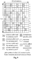
- Fig. 1 shows the pattern of a common reference signal and a downstream specific reference signal of a normal cyclic prefix frame structure according to the LTE standard, and when mapping the channel measurement reference signal, these locations should be avoid
- Figs. 2 to 10 are channel measurement reference signal patterns according to the embodiments of the present invention.
- the newly designed channel measurement reference signal with 4 or 8 ports achieves the downstream channel measurement of the LTE-A system; and when the number of actual antenna ports is equal to 1 or 2, the channel measurement reference signal reuses the common reference signal of the LTE-A system as a channel measurement reference signal to achieve the downstream channel measurement of the LTE-A system.
- the pattern of the CSI-RS with 4 ports and that of the first 4 ports of the CSI-RS with 8 ports are the same.
- the newly designed CSI-RS sends the pattern shown in Fig. 2 repeatedly with a certain period, and the newly designed CSI-RS within each period takes up one subframe to send.
- the reference signal frequency domain space of each port of antenna ports of the newly designed CSI-RS is 12 subcarriers, and each RB of the full bandwidth of the CSI-RS sending subframe repeats the pattern shown in Fig. 2 .
- the newly designed CSI-RS is mapped on the 14 th symbol of each subframe to send.
- the 0-port and 1-port of CSI-RS are mapped on the 1 st and 2 nd subcarriers adjacently, the 2-port and 3-port of CSI-RS are mapped on the 4 th and 5 th subcarriers adjacently, the 4-port and 5-port of CSI-RS are mapped on the 7 th and 8 th subcarriers adjacently, and the 6-port and 7-port of CSI-RS are mapped on the 10 th and 11 th subcarriers adjacently.
- the newly designed channel measurement reference signal with 4 or 8 ports achieves downstream channel measurement of the LTE-A system; and when the number of actual antenna ports is equal to 1 or 2, the channel measurement reference signal reuses the common reference signal of the LTE-A system as a channel measurement reference signal to achieve the downstream channel measurement of the LTE-A system.
- the pattern of the CSI-RS with 4 ports and that of the first 4 ports of the CSI-RS with 8 ports are the same.
- the newly designed CSI-RS with 4 or 8 ports sends the pattern shown in Fig. 3 repeatedly with a certain period, and the newly designed CSI-RS within each period takes up one subframe to send.
- the reference signal frequency domain space of each port of antenna ports of the newly designed CSI-RS is 8 subcarriers, and each two RBs of the full bandwidth of the CSI-RS sending subframe repeats the pattern shown in Fig. 3 .
- the newly designed CSI-RS is mapped on the 14 th symbol of each subframe to send.
- the 0 port of CSI-RS is mapped on the 1 st , 9 th , and 17 th subcarriers
- the 1-port of CSI-RS is mapped on the 2 nd , 10 th , and 18 th subcarriers
- the 2-port of CSI-RS is mapped on the 3 rd , 11 th , and 19 th subcarriers
- the 3-port of CSI-RS is mapped on the 4 th , 12 th , and 20 th subcarriers
- the 4-port of CSI-RS is mapped on the 5 th , 13 th , and 21 st subcarriers
- the 5-port of CSI-RS is mapped on the 6 th , 14 th , and 22 nd subcarriers
- the 6-port of CSI-RS is mapped on the 7 th , 15 th , and 23 rd subcarriers
- the 7-port of CSI-RS is mapped on the 8 th
- the newly designed channel measurement reference signal with 4 or 8 ports achieves the downstream channel measurement of the LTE-A system; and when the number of actual antenna ports is equal to 1 or 2, the channel measurement reference signal reuses the common reference signal of the LTE-A system as a channel measurement reference signal to achieve the downstream channel measurement of the LTE-A system.
- the pattern of the CSI-RS with 4 ports and that of the first 4 ports of the CSI-RS with 8 ports are the same.
- the newly designed CSI-RS with 4 or 8 ports sends the pattern shown in Fig. 4 repeatedly with a certain period, and the newly designed CSI-RS within each period takes up one subframe to send.
- the reference signal frequency domain space of each port of antenna ports of the newly designed CSI-RS is 6 subcarriers, and each RB of the full bandwidth of the CSI-RS sending subframe repeats the pattern shown in Fig. 4 .
- the newly designed CSI-RS is mapped on the 11 th and 14 th symbols of each subframe to send.
- the 0-port and 1-port of CSI-RS are mapped on the 1 st and 2 nd subcarriers of the 11 th symbol adjacently, the 2-port and 3-port of CSI-RS are mapped on the 4 th and 5 th subcarriers of the 11 th symbol adjacently, the 4-port and 5-port of CSI-RS are mapped on the 7 th and 8 th subcarriers of the 11 th symbol adjacently, the 6-port and 7-port of CSI-RS are mapped on the 10 th and 11 th subcarriers of the 11 th symbol adjacently; or the 0-port and 1-port of CSI-RS are mapped on the 7 th and 8 th subcarriers of the 14 th symbol adjacently, the 2-port and 3-port of CSI-RS are mapped on the 10 th and 11 th subcarriers of the 14 th symbol adjacently, the 4-port and 5-port of CSI-RS are mapped on the 1 st and 2 nd subcarriers of the 14 th
- the newly designed channel measurement reference signal with 4 or 8 ports achieves the downstream channel measurement of the LTE-A system; and when the number of actual antenna ports is equal to 1 or 2, the channel measurement reference signal reuses the common reference signal of the LTE-A system as a channel measurement reference signal to achieve the downstream channel measurement of the LTE-A system.
- the pattern of the CSI-RS with 4 ports and that of the first 4 ports of the CSI-RS with 8 ports are the same.
- the newly designed CSI-RS with 4 or 8 ports sends the pattern shown in Fig. 5 repeatedly with a certain period, and the newly designed CSI-RS within each period takes up one subframe to send.
- the reference signal frequency domain space of each port of antenna ports of the newly designed CSI-RS is 24 subcarriers, and each two RBs of the full bandwidth of the CSI-RS sending subframe repeats the pattern shown in Fig. 5 .
- the newly designed CSI-RS is mapped on the 14 th symbol of each subframe to send.
- the 0 port of CSI-RS is mapped on the 3 rd subcarrier, the 1-port of CSI-RS is mapped on the 6 th subcarrier, the 2-port of CSI-RS is mapped on the 9 th subcarrier, the 3-port of CSI-RS is mapped on the 12 th subcarrier, the 4-port of CSI-RS is mapped on the 15 th subcarrier, the 5-port of CSI-RS is mapped on the 18 th subcarrier, the 6-port of CSI-RS is mapped on the 21 th subcarrier, and the 7-port of CSI-RS is mapped on the 24 th subcarrier.
- the newly designed channel measurement reference signal with 4 or 8 ports achieves the downstream channel measurement of the LTE-A system; and when the number of actual antenna ports is equal to 1 or 2, the channel measurement reference signal reuses the common reference signal of the LTE-A system as a channel measurement reference signal to achieve the downstream channel measurement of the LTE-A system.
- the pattern of CSI-RS with 4 ports and that of the first 4 ports of the CSI-RS with 8 ports are the same.
- the newly designed CSI-RS with 4 or 8 ports sends the pattern shown in Fig. 6 repeatedly with a certain period, and the newly designed CSI-RS within each period takes up one subframe to send.
- the reference signal frequency domain space of each port of antenna ports of the newly designed CSI-RS is 12 subcarriers, and each RB of the full bandwidth of the CSI-RS sending subframe repeats the pattern shown in Fig. 6 .
- the newly designed CSI-RS is mapped on the 11 th symbol of each subframe to send.
- the 0-port and 1-port of CSI-RS are mapped on the 1 st and 2 nd subcarriers adjacently, the 2-port and 3-port of CSI-RS are mapped on the 4 th and 5 th subcarriers adjacently, the 4-port and 5-port of CSI-RS are mapped on the 7 th and 8 th subcarriers adjacently, the and 6-port and 7-port of CSI-RS are mapped on the 10 th and 11 th subcarriers adjacently.
- the patterns of the CSI-RS with 4 ports and that of the first 4 ports of the CSI-RS with 8 ports are the same.
- the pattern of the CSI-RS with 1 port and that of the first port of the CSI-RS with 2 ports are the same, the pattern of the CSI-RS with 2 ports and that of the first 2 ports of the CSI-RS with 4 ports are the same, and the pattern of the CSI-RS with 4 ports and that of the first 4 ports of the CSI-RS 8 ports are the same.
- the CSI-RS sends the pattern shown in Fig. 7 repeatedly with a certain period, and the newly designed CSI-RS within each period takes up one subframe to send.
- the reference signal frequency domain space of each port of antenna ports of the newly designed CSI-RS is 12 subcarriers, and each RB of the full bandwidth of the CSI-RS sending subframe repeats the pattern shown in Fig. 7 .
- the newly designed CSI-RS is mapped on the 6 th symbol of each subframe to send.
- the 0-port and 1-port of CSI-RS are mapped on the 1 st and 2 nd subcarriers adjacently, the 2-port and 3-port of CSI-RS are mapped on the 4 th and 5 th subcarriers adjacently, the 4-port and 5-port of CSI-RS are mapped on the 7 th and 8 th subcarriers adjacently, and the 6-port and 7-port of CSI-RS are mapped on the 10 th and 11 th subcarriers adjacently.
- the newly designed channel measurement reference signal with 4 or 8 ports achieves the downstream channel measurement of the LTE-A system; and when the number of actual antenna ports is equal to 1 or 2, the channel measurement reference signal reuses the common reference signal of the LTE-A system as a channel measurement reference signal to achieve the downstream channel measurement of the LTE-A system.
- the pattern of the CSI-RS with 4 ports and that of the first 4 ports of the CSI-RS with 8 ports are the same.
- the newly designed CSI-RS with 4 or 8 ports sends the pattern shown in Fig. 8 repeatedly with a certain period, and the newly designed CSI-RS within each period takes up one subframe to send.
- the reference signal frequency domain space of each port of antenna ports of the newly designed CSI-RS is 12 subcarriers, and each RB of the full bandwidth of the CSI-RS sending subframe repeats the pattern shown in Fig. 6 .
- the 0-port to 3-port of the newly designed CSI-RS are mapped on the 6 th symbol of each subframe to send; and the 4-port to 7-port are mapped on the 11 th symbol of each subframe to send.
- the 0-port and 4-port of CSI-RS are mapped on the 1 st subcarrier, the 1-port and 5-port of CSI-RS are mapped on the 4 th subcarrier, the 2-port and 6-port of CSI-RS are mapped on the 7 th subcarrier, and the 3-port, 7-port and 4-port of CSI-RS are mapped on the 10 th subcarrier.
- the newly designed channel measurement reference signal with 4 or 8 ports achieves the downstream channel measurement of the LTE-A system; and when the number of actual antenna ports is equal to 1 or 2, the channel measurement reference signal reuses the common reference signal of the LTE-A system as a channel measurement reference signal to achieve the downstream channel measurement of the LTE-A system.
- the pattern of the CSI-RS with 4 ports and that of the first 4 ports of the CSI-RS with 8 port are the same.
- the newly designed CSI-RS with 4 or 8 port sends the pattern shown in Fig. 9 repeatedly with a certain period, and the newly designed CSI-RS within each period takes up one subframe to send.
- the reference signal frequency domain space of each port of antenna ports of the newly designed CSI-RS is 12 subcarriers, and each RB of the full bandwidth of the CSI-RS sending subframe repeats the pattern shown in Fig. 6 .
- the 0-port to 3-port of the newly designed CSI-RS are mapped on the 6 th symbol of each subframe to send; and the 4-port to 7-port are mapped on the 11 th symbol of each subframe to send.
- the 0-port and 1-port of CSI-RS are sent on the 1 st and 2 nd subcarriers adjacently, the 2-port and 3-port of CSI-RS are mapped on the 7 th and 8 th subcarriers adjacently, and the frequency domain locations of the 4-port, 5-port, 6-port, and 7-port are the same as those of the 0-port, 1-port, 2-port, and 3-port respectively.
- the channel measurement reference signal When the number of actual antenna ports is equal to 4 or 8, the newly designed channel measurement reference signal with 4 or 8 ports achieves downstream channel measurement of the LTE-A system; and when the number of actual antenna ports is equal to 1 or 2, the channel measurement reference signal reuses the common reference signal of the LTE-A system as a channel measurement reference signal to achieve the downstream channel measurement of the LTE-A system.
- the pattern of the CSI-RS 4 ports and that of the first 4 ports of the CSI-RS with 8 ports are the same.
- the newly designed CSI-RS with 4 or 8 ports sends the pattern shown in Fig. 10 repeatedly with a certain period, and the newly designed CSI-RS within each period takes up one subframe to send.
- the reference signal frequency domain space of each port of antenna ports of the newly designed CSI-RS is 12 subcarriers, and each RB of the full bandwidth of the CSI-RS sending subframe repeats the pattern shown in Fig. 6 .
- the 0-port to 3-port of the newly designed CSI-RS are mapped on the 6 th symbol of each subframe to send; and the 4-port to 7-port are mapped on the 14 th symbol of each subframe to send.
- the 0-port and 1-port of CSI-RS are sent on the 1 st and 2 nd subcarriers adjacently, the 2-port and 3-port of CSI-RSs are mapped on the 7 th and 8 th subcarriers adjacently, and the frequency domain locations of the 4-port, 5-port, 6-port, and 7-port are the same as those of the 0-port, 1-port, 2-port, and 3-port respectively.
- Fig. 11 is a block diagram of a system 1100 for sending a channel measurement reference signal according to the present invention. As shown in Fig. 11 , this system comprises: a sending module 1102, configured to send each port of the channel measurement reference signal in one subframe or two adjacent subframes during one sending period and send each port of the channel measurement reference signal repeatedly in full bandwidth with equal space in the unit of a predetermined composition unit.
- a sending module 1102 configured to send each port of the channel measurement reference signal in one subframe or two adjacent subframes during one sending period and send each port of the channel measurement reference signal repeatedly in full bandwidth with equal space in the unit of a predetermined composition unit.
- the sending module 1102 can comprise: a first channel measurement reference signal port number setting unit 1102a, configured to newly design channel measurement reference signals with ⁇ 1, 2, 4, 8 ⁇ port(s), wherein the pattern of the channel measurement reference signal with 1 port and that of the first port of the channel measurement reference signal with 2 ports are the same, the pattern of the channel measurement reference signal with 2 ports and that of the first ports of the channel measurement reference signal with 4 ports are the same, and the pattern of the channel measurement reference signal with 4 ports and that of the first 4 ports of the channel measurement reference signal with 8 ports are the same; and a second channel measurement reference signal port number setting unit 1102b, configured to newly design channel measurement reference signals with ⁇ 4, 8 ⁇ ports, when the number of actual antenna ports is equal to 4 or 8, the newly designed channel measurement reference signal with 4 or 8 port achieves the downstream channel measurement of the long-term evolution advance system, and when the number of actual antenna ports is equal to 1 or 2, the common reference signal of the LTE system is reused as a channel measurement reference signals by the channel measurement reference signal, so as to
- the patterns of the channel measurement reference signals during different sending periods are the same, and the channel measurement reference signal is sent on the 6 th , 9 th , and 14 th symbols of the configured subframe, and the channel measurement reference signal is sent by taking a subframe of any number of 0, 2, 5, 10 or 20 as a period, and the frequency domain space of the equal space that the channel measurement reference signal predetermined composition unit is repeated with is ⁇ 6, 8, 12, 16, 24, 30, 36, 42, 48 ⁇ .
- system for sending a channel measurement reference signal can further comprise: a repeated sending unit 1104, configured to repeatedly send the channel measurement reference signal and the newly designed channel measurement reference signals in full bandwidth with equal space by taking one or two RBs as the predetermined composition unit, and the channel measurement reference signal with 8 ports is located on the 14 th OFDM symbol of the sending subframe.
- a repeated sending unit 1104 configured to repeatedly send the channel measurement reference signal and the newly designed channel measurement reference signals in full bandwidth with equal space by taking one or two RBs as the predetermined composition unit, and the channel measurement reference signal with 8 ports is located on the 14 th OFDM symbol of the sending subframe.
- the present invention sends the predetermined composition unit by each RB, it should be understood that the present invention can further be applied in sending the predetermined composition unit in full bandwidth with equal space by spacing 2 RBs, or 1.5 RBs, or 2.5 RBs, or 3 RBs.
- the above sending method of the present invention can be implemented through general-purpose computing devices and they can be put together on single computing device or distributed on a network consisted of a plurality of computing devices, optionally, they can be implemented using computing device executable program code, therefore, they can be executed by computing devices by storing them in a storage device, or they can be made into each integrated circuit module respectively or they can be implemented by making a plurality of modules or steps of them into single integrated module respectively.
- the present invention is not restricted to any particular hardware and software combination.
- the CRS sending of the LTE system is retained, the effect to the LTE users is very little, and the reference signal information required by high stage MIMO and COMP is provided, which is advantageous for the LTE-Advanced users to improve single link quality.
- the performance degradation of LTE users is reduced, the design costs less, the performance of channel measurement can be ensured, and the LTE-A system throughput can be improved.
Landscapes
- Engineering & Computer Science (AREA)
- Signal Processing (AREA)
- Computer Networks & Wireless Communication (AREA)
- Power Engineering (AREA)
- Mobile Radio Communication Systems (AREA)
Claims (18)
- Ein Verfahren zum Senden von Kanalmessreferenzsignalen, das folgende Schritte umfasst:während einer Sendeperiode, durch eine Basisstation Senden des Kanalmessreferenzsignals jedes Anschlusses in einem Unterrahmen oder zwei benachbarten Unterrahmen und wiederholtes Senden des Kanalmessreferenzsignals jedes Anschlusses in voller Bandbreite mit gleichem Raum in der Einheit einer vorbestimmten zusammengesetzten Einheit,wobei jede vorbestimmte zusammengesetzte Einheit mindestens einen Ressourcenblock (RB) umfasst; wobei das Kanalmessreferenzsignal gesendet wird, indem N Unterrahmen als Zeitintervall der Kanalmessreferenzsignal-Zeitdomäne genommen werden, gekennzeichnet durchdas Entwickeln von Kanalmessreferenzsignalen mit {1, 2, 4, 8} Anschlüssen,wobei das Muster des Kanalmessreferenzsignals mit 1 Anschluss und dasjenige des ersten Anschlusses des Kanalmessreferenzsignals mit 2 Anschlüssen identisch sind, das Muster des Kanalmessreferenzsignals mit 2 Anschlüssen und dasjenige der ersten 2 Anschlüsse des Kanalmessreferenzsignals mit 4 Anschlüssen identisch sind, und das Muster des Kanalmessreferenzsignals mit 4 Anschlüssen und dasjenige der ersten 4 Anschlüsse des Kanalmessreferenzsignals mit 8 Anschlüssen identisch sind;wobei der Frequenzdomänenraum des gleichen Raums, mit dem die vorbestimmte zusammengesetzte Kanalmessreferenzsignaleinheit wiederholt wird, M ist.
- Das Verfahren zum Senden eines Kanalmessreferenzsignals gemäß Anspruch 1, dadurch gekennzeichnet, dass Kanalmessreferenzsignale mit {4, 8} Anschlüssen neu entwickelt werden,
wenn die Anzahl tatsächlicher Antennenanschlüsse gleich 4 oder 8 ist, erzielt das neu entwickelte Kanalmessreferenzsignal mit 4 oder 8 Anschlüssen eine Empfangskanalmessung des Long-Term Evolution-Advanced Systems; und
wenn die Anzahl tatsächlicher Antennenanschlüsse gleich 1 oder 2 ist, wird das gemeinsame Referenzsignal des LTE-Systems vom Kanalmessreferenzsignal als Kanalmessreferenzsignal wieder-verwendet, um so die Empfangskanalmessung des Long-Term Evolution Advanced Systems zu erreichen;
wobei das Muster des Kanalmessreferenzsignals mit 4 Anschlüssen und dasjenige der ersten 4 Anschlüsse des Kanalmessreferenzsignals mit 8 Anschlüssen identisch sind. - Das Verfahren zum Senden eines Kanalmessreferenzsignals gemäß Anspruch 1, dadurch gekennzeichnet, dass die Muster von Kanalmessreferenzsignalen während verschiedener Sendezeiträume identisch sind.
- Das Verfahren zum Senden eines Kanalmessreferenzsignals gemäß Anspruch 1, dadurch gekennzeichnet, dass das Kanalmessreferenzsignal auf dem 6., dem 9. und dem 14. Zeichen des konfigurierten Unterrahmens gesendet wird.
- Das Verfahren zum Senden eines Kanalmessreferenzsignals gemäß Anspruch 1, dadurch gekennzeichnet, dass N eine beliebige Zahl aus 0, 2, 5, 10 oder 20 ist.
- Das Verfahren zum Senden eines Kanalmessreferenzsignals gemäß Anspruch 1, dadurch gekennzeichnet, dass M eines von Folgendem ist: {6, 8, 12, 16, 24, 30, 36, 42, 48}.
- Das Verfahren zum Senden eines Kanalmessreferenzsignals gemäß Anspruch 2, dadurch gekennzeichnet, dass die neu entwickelten Kanalmessreferenzsignale wiederholt in voller Bandbreite mit gleichem Raum gesendet werden, indem ein RB als vorbestimmte zusammengesetzte Einheit genommen wird, und wobei das Kanalmessreferenzsignal mit 8 Anschlüssen sich auf dem 14. OFDM-Zeichen des sendenden Unterrahmens befindet, wobei der 0 Anschluss des Kanalmessreferenzsignals und der 1-Anschluss des Kanalmessreferenzsignals nebeneinander auf den 1, und den 2. Hilfsträger abgebildet werden, der 2-Anschluss des Kanalmessreferenzsignals und der 3-Anschluss des Kanalmessreferenzsignals nebeneinander auf den 4. und den 5. Hilfsträger abgebildet werden, der 4-Anschluss des Kanalmessreferenzsignals und der 5-Anschluss des Kanalmessreferenzsignals nebeneinander auf den 7. und den 8. Hilfsträger abgebildet werden und der 6-Anschluss des Kanalmessreferenzsignals und der 7-Anschluss des Kanalmessreferenzsignals nebeneinander auf den 10. und den 11. Hilfsträger abgebildet werden.
- Das Verfahren zum Senden eines Kanalmessreferenzsignals gemäß Anspruch 2, dadurch gekennzeichnet, dass die neu entwickelten Kanalmessreferenzsignale wiederholt in voller Bandbreite mit gleichem Raum gesendet werden, indem zwei RBs als die vorbestimmte zusammengesetzte Einheit genommen werden und das Kanalmessreferenzsignal mit 8 Anschlüssen sich auf dem 14. OFDM-Zeichen des sendenden Unterrahmens befindet, wobei
der 0-Anschluss des Kanalmessreferenzsignals auf den 1., den 9. und den 17. Hilfsträger abgebildet wird,
der 1-Anschluss des Kanalmessreferenzsignals auf den 2., den 10. und den 18. Hilfsträger abgebildet wird,
der 2-Anschluss des Kanalmessreferenzsignals auf dem 3., dem 11. und dem 19. Hilfsträger abgebildet wird,
der 3-Anschluss des Kanalmessreferenzsignals auf den 4., den 12. und den 20. Hilfsträger abgebildet wird,
der 4-Anschluss des Kanalmessreferenzsignals auf den 5., den 13. und den 21. Hilfsträger abgebildet wird,
der 5-Anschluss des Kanalmessreferenzsignals auf den 6., den 14. und den 22. Hilfsträger abgebildet wird,
der 6-Anschluss des Kanalmessreferenzsignals auf den 7., den 15. und den 23. Hilfsträger abgebildet wird, und
der 7-Anschluss des Kanalmessreferenzsignals auf den 8., den 16. und den 24. Hilfsträger abgebildet wird. - Das Verfahren zum Senden eines Kanalmessreferenzsignals gemäß Anspruch 2, dadurch gekennzeichnet, dass die neu entwickelten Kanalmessreferenzsignale wiederholt in voller Bandbreite mit gleichem Raum gesendet werden, indem ein RB als vorbestimmte zusammengesetzte Einheit genommen wird und das Kanalmessreferenzsignal mit 8 Anschlüssen sich auf dem 11. und dem 14. OFDM-Zeichen des sendenden Unterrahmens befindet, wobei
auf dem 11. Zeichen der 0-Anschluss und der 1-Anschluss des Kanalmessreferenzsignals nebeneinander auf den 1. und den 2. Hilfsträger abgebildet werden, der 2-Anschluss und der 3-Anschluss des Kanalmessreferenzsignals nebeneinander auf den 4. und den 5. Hilfsträger abgebildet werden, der 4-Anschluss und der 5-Anschluss des Kanalmessreferenzsignals nebeneinander auf den 7. und den 8. Hilfsträger abgebildet werden und der 6-Anschluss und der 7-Anschluss des Kanalmessreferenzsignals nebeneinander auf den 10. und den 11. Hilfsträger abgebildet werden; und wobei auf dem 14. OFDN-Zeichen der 0-Anschluss und der 1-Anschluss des Kanalmessreferenzsignals nebeneinander auf den 7. und den 8. Hilfsträger des 14. Zeichens abgebildet werden, der 2-Anschluss und der 3-Anschluss des Kanalmessreferenzsignals nebeneinander auf den 10. und den 11. Hilfsträger des 14. Zeichens abgebildet werden, der 4-Anschluss und der 5-Anschluss des Kanalmessreferenzsignals nebeneinander auf den 1. und den 2. Hilfsträger des 14. Zeichens abgebildet werden, und wobei der 6-Anschluss und der 7-Anschluss des Kanalmessreferenzsignals nebeneinander auf den 4. und den 5. Hilfsträger des 14. Zeichens abgebildet werden. - Das Verfahren zum Senden eines Kanalmessreferenzsignals gemäß Anspruch 2, dadurch gekennzeichnet, dass die neu entwickelten Kanalmessreferenzsignale wiederholt in voller Bandbreite mit gleichem Raum gesendet werden, indem zwei RBs als vorbestimmte zusammengesetzte Einheit genommen werden und das Kanalmessreferenzsignal mit 8 Anschlüssen sich auf dem 14. OFDM-Zeichen des sendenden Unterrahmens befindet, wobei
der 0-Anschluss des Kanalmessreferenzsignals auf den 3. Hilfsträger abgebildet wird, der 1-Anschluss des Kanalmessreferenzsignals auf den 6. Hilfsträger abgebildet wird, der 2-Anschluss des Kanalmessreferenzsignals auf den 9. Hilfsträger abgebildet wird, der 3-Anschluss des Kanalmessreferenzsignals auf den 12. Hilfsträger abgebildet wird, der 4-Anschluss des Kanalmessreferenzsignals auf den 15. Hilfsträger abgebildet wird, der 5-Anschluss des Kanalmessreferenzsignals auf den 18. Hilfsträger abgebildet wird, der 6-Anschluss des Kanalmessreferenzsignals auf den 21. Hilfsträger abgebildet wird und der 7-Anschluss des Kanalmessreferenzsignals auf den 24. Hilfsträger abgebildet wird. - Das Verfahren zum Senden eines Kanalmessreferenzsignals gemäß Anspruch 2, dadurch gekennzeichnet, dass die neu entwickelten Kanalmessreferenzsignale wiederholt in voller Bandbreite mit gleichem Raum gesendet werden, indem ein RB als vorbestimmte zusammengesetzte Einheit genommen wird, und die Kanalmessung mit 8 Anschlüssen Referenzsignal sich auf dem 6. und 11. OFDM-Zeichen des sendenden Unterrahmens befindet, wobei
der 0-Anschluss und der 4-Anschluss des Kanalmessreferenzsignals auf den 1. Hilfsträger abgebildet werden, der 1-Anschluss und der 5-Anschluss des Kanalmessreferenzsignals auf den 4. Hilfsträger abgebildet werden, der 2-Anschluss und der 6-Anschluss des Kanalmessreferenzsignals auf den 7. Hilfsträger abgebildet werden und der 3-Anschluss und der 7-Anschluss des Kanalmessreferenzsignals auf den 10. Hilfsträger abgebildet werden. - Das Verfahren zum Senden eines Kanalmessreferenzsignals gemäß Anspruch 2, dadurch gekennzeichnet, dass das Kanalmessreferenzsignal wiederholt in voller Bandbreite mit gleichem Raum gesendet wird, indem ein RB als vorbestimmte zusammengesetzte Einheit genommen wird, und das Kanalmessreferenzsignal mit 8 Anschlüssen sich auf dem 6. OFDM-Zeichen des sendenden Unterrahmens befindet, wobei
der 0-Anschluss und der 1-Anschluss nebeneinander auf den 1. und den 2. Hilfsträger abgebildet werden, der 2-Anschluss und der 3-Anschluss des Kanalmessreferenzsignals nebeneinander auf den 7. und den 8. Hilfsträger abgebildet werden, die Positionen der Frequenzdomänen des 4-Anschlusses, des 5-Anschlusses, 6-Anschlusses und 7-Anschlusses des Kanalmessreferenzsignals identisch sind mit denjenigen des 0-Anschlusses, 1-Anschlusses, 2-Anschlusses beziehungsweise 3-Anschlusses des Kanalmessreferenzsignals, und jeder Anschluss des Kanalmessreferenzsignals bei einer Konfiguration an verschiedenen Antennenanschlüssen gleich ist, und die Abbildung von Kanalmessreferenzsignalen mit 1, 2, 4 und 8 Anschluss/Anschlüssen gleichzeitig unterstützt wird. - Das Verfahren zum Senden eines Kanalmessreferenzsignals gemäß Anspruch 2, dadurch gekennzeichnet, dass das Kanalmessreferenzsignal wiederholt in voller Bandbreite mit gleichem Raum gesendet wird, indem ein RB als vorbestimmte zusammengesetzte Einheit genommen wird, wobei
das Kanalmessreferenzsignal mit 8 Anschlüssen sich auf dem 6. und dem 11. OFDM-Zeichen des sendenden Unterrahmens befindet, der 0-Anschluss von CSI-RS auf den 1. Hilfsträger des 6. OFDM-Zeichens abgebildet wird, der 1-Anschluss von CSI-RS auf den 4. Hilfsträger des 6. OFDM-Zeichens abgebildet wird, der 2-Anschluss von CSI-RS auf den 7. Hilfsträger des 6. OFDM-Zeichens abgebildet wird, der 3-Anschluss von CSI-RS auf den 10. Hilfsträger des 6. OFDM-Zeichens abgebildet wird, der 4-Anschluss von CSI-RS auf den 1. Hilfsträger des 11. OFDM-Zeichens abgebildet wird, der 5-Anschluss von CSI-RS auf den 4. Hilfsträger des 11. OFDM-Zeichens abgebildet wird, der 6-Anschluss von CSI-RS auf den 7. Hilfsträger des 11. OFDM-Zeichens abgebildet wird und der 7-Anschluss von CSI-RS auf den 10. Hilfsträger des 11. OFDM-Zeichens abgebildet wird. - Das Verfahren zum Senden eines Kanalmessreferenzsignals gemäß Anspruch 2, dadurch gekennzeichnet, dass das Kanalmessreferenzsignal wiederholt in voller Bandbreite mit gleichem Raum gesendet wird, indem ein RB als vorbestimmte zusammengesetzte Einheit genommen wird, wobei
das Kanalmessreferenzsignal mit 8 Anschlüssen sich auf dem 6. und dem 11. OFDM-Zeichen des sendenden Unterrahmens befindet, der 0-Anschluss und der 1-Anschluss von CSI-RS nebeneinander auf den 1. und den 2. Hilfsträger des 6. OFDM-Zeichens abgebildet werden, der 2-Anschluss und der 3-Anschluss von CSI-RS nebeneinander auf den 7. und den 8. Hilfsträger des 6. OFDM-Zeichens abgebildet werden und der 4-Anschluss, der 5-Anschluss, 6-Anschluss und 7-Anschluss auf das 11. Zeichen abgebildet werden, wobei die Positionen der Frequenzdomänen derselben identisch sind mit denjenigen des 0-Anschlusses, 1-Anschlusses, 2-Anschlusses beziehungsweise des 3-Anschlusses. - Das Verfahren zum Senden eines Kanalmessreferenzsignals gemäß Anspruch 2, dadurch gekennzeichnet, dass das Kanalmessreferenzsignal wiederholt in voller Bandbreite mit gleichem Raum gesendet wird, indem ein RB als vorbestimmte zusammengesetzte Einheit genommen wird, wobei
das Kanalmessreferenzsignal mit 8 Anschlüssen sich auf dem 6. und dem 14. OFDM-Zeichen des sendenden Unterrahmens befindet, der 0-Anschluss und der 1-Anschluss von CSI-RS nebeneinander auf den 1, und den 2. Hilfsträger des 6. OFDM-Zeichens abgebildet werden, der 2-Anschluss und der 3-Anschluss von CSI-RS nebeneinander auf den 7. und den 8. Hilfsträger des 6. OFDM-Zeichens abgebildet werden und der 4-Anschluss, der 5-Anschluss, 6-Anschluss und 7-Anschluss auf das 14. Zeichen abgebildet werden, wobei die Positionen der Frequenzdomänen derselben identisch sind mit denjenigen des 0-Anschlusses, 1-Anschlusses, 2-Anschlusses beziehungsweise des 3-Anschlusses. - Ein System zum Senden eines Kanalmessreferenzsignals, das Folgendes umfasst:ein Sendemodul (1102), konfiguriert, um das Kanalmessreferenzsignal jedes Anschlusses während einer Sendeperiode in einem Unterrahmen oder zwei benachbarten Unterrahmen zu senden und das Kanalmessreferenzsignal jedes Anschlusses wiederholt in voller Bandbreite mit gleichem Raum in der Einheit einer vorbestimmten zusammengesetzten Einheit zu senden,wobei jede vorbestimmte zusammengesetzte Einheit mindestens einen Ressourcenblock (RB) umfasst; wobei das Kanalmessreferenzsignal gesendet wird, indem N Unterrahmen als ein Zeitintervall der Kanalmessreferenzsignal-Zeitdomäne genommen werden,dadurch gekennzeichnet, dass das Sendemodul (1102) Folgendes umfasst:eine erste Kanalmessreferenzsignal-Anschlussnummereinstelleinheit (1102a), die konfiguriert ist, um Kanalmessreferenzsignale mit {1, 2, 4, 8} Anschluss/Anschlüssen zu entwickeln, wobei das Muster des Kanalmessreferenzsignals mit 1 Anschluss und dasjenige des ersten Anschlusses des Kanalmessreferenzsignals mit 2 Anschlüssen identisch sind, das Muster des Kanalmessreferenzsignals mit 2 Anschlüssen und dasjenige der ersten 2 Anschlüsse des Kanalmessreferenzsignals mit 4 Anschlüssen identisch sind und das Muster des Kanalmessreferenzsignals mit 4 Anschlüssen und dasjenige der ersten 4 Anschlüsse des Kanalmessreferenzsignals mit 8 Anschlüssen identisch sind; undeine zweite Kanalmessreferenzsignal-Anschlussnummereinstelleinheit (1102b), die konfiguriert ist, um Kanalmessreferenzsignale mit {4, 8} Anschlüssen zu entwickeln; wenn die Anzahl tatsächlicher Antennenanschlüsse gleich 4 oder 8 ist, erreicht das neu entwickelte Kanalmessreferenzsignal mit 4 oder 8 Anschlüssen die Empfangskanalmessung des Long-Term Evolution Advanced Systems; und wenn die Anzahl tatsächlicher Antennenanschlüsse gleich 1 oder 2 ist, wird das gemeinsame Referenzsignal des LTE--Systems vom Kanalmessreferenzsignal als Kanalmessreferenzsignal wiederverwendet, um so die Empfangskanalmessung des Long-Term Evolution Advanced Systems zu erreichen, wobei das Muster des Kanalmessreferenzsignals mit 4 Anschlüssen und dasjenige der ersten 4 Anschlüsse des Kanalmessreferenzsignals mit 8 Anschlüssen identisch sind.
- Das System zum Senden eines Kanalmessreferenzsignals gemäß Anspruch 16, dadurch gekennzeichnet, dass die Muster der Kanalmessreferenzsignale während verschiedener Sendeperioden identisch sind, wobei das Kanalmessreferenzsignal auf dem 6., dem 9. und dem 14. Zeichen des konfigurierten Unterrahmens gesendet wird und das Kanalmessreferenzsignal gesendet wird, indem ein Unterrahmen einer beliebigen Zahl aus 0, 2, 5, 10 oder 20 als einer Periode genommen wird, und wobei der Frequenzdomänenraum des gleichen Raums, mit dem die vorbestimmte zusammengesetzte Kanalmessreferenzsignal-Einheit wiederholt wird, (6, 8, 12, 16, 24, 30, 36, 42, 48) ist.
- Das System zum Senden eines Kanalmessreferenzsignals gemäß Anspruch 16, dadurch gekennzeichnet, dass es weiter Folgendes umfasst:eine Einheit (1104) zum wiederholten Senden, konfiguriert, um das Kanalmessreferenzsignal und die neu entwickelten Kanalmessreferenzsignale in voller Bandbreite mit gleichem Raum wiederholt zu senden, indem ein oder zwei RBs als vorbestimmte zusammengesetzte Einheit genommen werden, wobei das Kanalmessreferenzsignal mit 8 Anschlüssen sich auf dem 14. OFDM-Zeichen des sendenden Unterrahmens befindet.
Applications Claiming Priority (2)
| Application Number | Priority Date | Filing Date | Title |
|---|---|---|---|
| CN2009101661778A CN101997809B (zh) | 2009-08-18 | 2009-08-18 | 信道测量导频发送方法和系统 |
| PCT/CN2010/072586 WO2011020342A1 (zh) | 2009-08-18 | 2010-05-10 | 信道测量导频发送方法和系统 |
Publications (3)
| Publication Number | Publication Date |
|---|---|
| EP2469734A1 EP2469734A1 (de) | 2012-06-27 |
| EP2469734A4 EP2469734A4 (de) | 2013-10-02 |
| EP2469734B1 true EP2469734B1 (de) | 2017-03-01 |
Family
ID=43606603
Family Applications (1)
| Application Number | Title | Priority Date | Filing Date |
|---|---|---|---|
| EP10809475.6A Active EP2469734B1 (de) | 2009-08-18 | 2010-05-10 | Verfahren und system zum senden von kanalmesspilotfrequenzen |
Country Status (9)
| Country | Link |
|---|---|
| US (1) | US9313677B2 (de) |
| EP (1) | EP2469734B1 (de) |
| JP (1) | JP2013502773A (de) |
| KR (1) | KR101637060B1 (de) |
| CN (1) | CN101997809B (de) |
| BR (1) | BR112012003568B1 (de) |
| MX (1) | MX2012002036A (de) |
| RU (1) | RU2518493C2 (de) |
| WO (1) | WO2011020342A1 (de) |
Families Citing this family (10)
| Publication number | Priority date | Publication date | Assignee | Title |
|---|---|---|---|---|
| CN102158292B (zh) * | 2010-02-12 | 2016-01-20 | 中兴通讯股份有限公司 | 信道测量导频发送方法及基站 |
| US8743980B2 (en) * | 2010-08-12 | 2014-06-03 | Acer Incorporated | Method of designing reference signal pattern and related communication device |
| CN103138869B (zh) * | 2011-11-22 | 2015-08-19 | 中国移动通信集团公司 | 信道状态信息参考信号的发送方法、基站及中继 |
| EP2903368B1 (de) * | 2012-09-29 | 2016-09-14 | Huawei Technologies Co., Ltd. | Verfahren und vorrichtung zum senden und empfangen eines referenzsignals |
| CN103347298B (zh) * | 2012-12-31 | 2019-02-19 | 上海华为技术有限公司 | 参考信号配置方法和参考信号发送方法及相关设备 |
| US10348468B2 (en) | 2015-02-04 | 2019-07-09 | Lg Electronics Inc. | Method for transmitting and receiving signal in wireless communication system, and apparatus therefor |
| CN108024215A (zh) * | 2016-11-04 | 2018-05-11 | 中兴通讯股份有限公司 | 一种多播业务的传输方法及装置 |
| US10921367B2 (en) | 2019-03-06 | 2021-02-16 | Analog Devices, Inc. | Stable measurement of sensors methods and systems |
| FR3103345B1 (fr) | 2019-11-18 | 2022-07-29 | Pascal Roussel | Système d’adaptateur de communication pour filtre acoustique de protecteur individuel avec mixage des sons extérieurs |
| US12028198B2 (en) * | 2020-10-13 | 2024-07-02 | Intel Corporation | Phase tracking reference signal for 6G wireless communication |
Family Cites Families (15)
| Publication number | Priority date | Publication date | Assignee | Title |
|---|---|---|---|---|
| KR100617835B1 (ko) * | 2005-01-05 | 2006-08-28 | 삼성전자주식회사 | 통신 시스템에서 채널 품질 정보 송수신 장치 및 방법 |
| CN101090558A (zh) * | 2006-06-15 | 2007-12-19 | 华为技术有限公司 | 上行导频信号的发送方法及其系统 |
| WO2008054128A1 (en) | 2006-11-01 | 2008-05-08 | Lg Electronics Inc. | Method for allocating pilots |
| CN101184073A (zh) * | 2006-11-14 | 2008-05-21 | 中兴通讯股份有限公司 | 基于正交频分复用的多发射天线系统的导频信号发送方法 |
| US8300658B2 (en) | 2007-03-21 | 2012-10-30 | Motorola Mobility Llc | Apparatuses and methods for multi-antenna channel quality data acquisition in a broadcast/multicast service network using a multicast symbol |
| CN101286762B (zh) * | 2007-04-10 | 2013-08-28 | 华为技术有限公司 | 一种发送sounding导频的方法及发送装置 |
| US8050237B2 (en) | 2007-08-01 | 2011-11-01 | Broadcom Corporation | Synchronization channel noise power estimation |
| US8369450B2 (en) | 2007-08-07 | 2013-02-05 | Samsung Electronics Co., Ltd. | Pilot boosting and traffic to pilot ratio estimation in a wireless communication system |
| CN101106395A (zh) * | 2007-08-15 | 2008-01-16 | 中兴通讯股份有限公司 | 控制信令和测量导频的发射方法 |
| KR101376233B1 (ko) * | 2007-10-02 | 2014-03-21 | 삼성전자주식회사 | 주파수 분할 다중 접속 방식의 시스템에서 제어 채널의자원 할당 장치 및 방법 |
| CN101162987B (zh) | 2007-11-10 | 2011-06-22 | 中兴通讯股份有限公司 | 一种时分双工系统上行特殊时隙中导频信号的发送方法 |
| US9647810B2 (en) * | 2009-03-17 | 2017-05-09 | Samsung Electronics Co., Ltd. | Method and system for mapping pilot signals in multi-stream transmissions |
| KR101474087B1 (ko) | 2009-03-19 | 2014-12-22 | 닛본 덴끼 가부시끼가이샤 | 개선된 채널 품질 표시자 방법 |
| WO2011037427A2 (ko) * | 2009-09-27 | 2011-03-31 | 엘지전자 주식회사 | 무선 통신 시스템에서 참조 신호 전송 방법 및 장치 |
| KR101819502B1 (ko) * | 2010-02-23 | 2018-01-17 | 엘지전자 주식회사 | 간섭 측정 방법 및 단말과, 간섭 정보 수신 방법 및 기지국 |
-
2009
- 2009-08-18 CN CN2009101661778A patent/CN101997809B/zh active Active
-
2010
- 2010-05-10 KR KR1020127006699A patent/KR101637060B1/ko active Active
- 2010-05-10 US US13/259,813 patent/US9313677B2/en active Active
- 2010-05-10 RU RU2012108558/07A patent/RU2518493C2/ru active
- 2010-05-10 MX MX2012002036A patent/MX2012002036A/es active IP Right Grant
- 2010-05-10 EP EP10809475.6A patent/EP2469734B1/de active Active
- 2010-05-10 BR BR112012003568-1A patent/BR112012003568B1/pt active IP Right Grant
- 2010-05-10 JP JP2012525033A patent/JP2013502773A/ja active Pending
- 2010-05-10 WO PCT/CN2010/072586 patent/WO2011020342A1/zh not_active Ceased
Non-Patent Citations (1)
| Title |
|---|
| None * |
Also Published As
| Publication number | Publication date |
|---|---|
| RU2518493C2 (ru) | 2014-06-10 |
| RU2012108558A (ru) | 2013-10-20 |
| US20120140718A1 (en) | 2012-06-07 |
| CN101997809B (zh) | 2013-09-11 |
| BR112012003568B1 (pt) | 2021-06-22 |
| WO2011020342A1 (zh) | 2011-02-24 |
| EP2469734A4 (de) | 2013-10-02 |
| US9313677B2 (en) | 2016-04-12 |
| EP2469734A1 (de) | 2012-06-27 |
| MX2012002036A (es) | 2012-06-27 |
| JP2013502773A (ja) | 2013-01-24 |
| BR112012003568A2 (pt) | 2016-04-19 |
| KR101637060B1 (ko) | 2016-07-06 |
| CN101997809A (zh) | 2011-03-30 |
| KR20120048014A (ko) | 2012-05-14 |
Similar Documents
| Publication | Publication Date | Title |
|---|---|---|
| EP2469734B1 (de) | Verfahren und system zum senden von kanalmesspilotfrequenzen | |
| CN109995498B (zh) | 一种dmrs指示和接收方法,发射端和接收端 | |
| CN108809609B (zh) | 一种dmrs指示和接收方法,发射端和接收端 | |
| KR101683124B1 (ko) | 하향링크 mimo시스템에 있어서 rs 전송 방법 | |
| CN101924610B (zh) | Lte-a系统中信道状态信息参考信号csi-rs的设计与分配方法 | |
| US11283569B2 (en) | Data transmission method, network device, and terminal device | |
| CN102420685B (zh) | 一种传输控制信息的方法及装置 | |
| CN102055707B (zh) | 信道测量导频映射方法及装置 | |
| CN101841828A (zh) | Lte-a系统中信道测量导频的发送方法 | |
| KR101343528B1 (ko) | 멀티 브로드캐스트 단일 주파수 네트워크 서브프레임, 그리고 사용자 데이터 채널의 발송 방법 및 장치 | |
| KR102711905B1 (ko) | Nr 시스템을 위한 복조 참조신호 패턴 설정 정보 송수신 방법 및 장치 | |
| US11101957B2 (en) | Reference signal sending method and apparatus | |
| CN102158292B (zh) | 信道测量导频发送方法及基站 | |
| CN101677306A (zh) | 一种导频配置方法和装置 | |
| KR102236091B1 (ko) | 레퍼런스 신호의 매핑 방법 및 장치 | |
| CN101848017B (zh) | 基于lte-a用户专用资源的信道测量导频配置方法 | |
| EP3515137A1 (de) | Signalressourcenkonfigurationsverfahren, endgerät und zugriffsnetzwerkvorrichtung | |
| CN102215197A (zh) | 一种信道测量导频映射方法及基站 | |
| KR20100099644A (ko) | 다중안테나를 갖는 무선 통신 시스템에서 하향링크 기준 신호 전송 및 수신 방법 |
Legal Events
| Date | Code | Title | Description |
|---|---|---|---|
| PUAI | Public reference made under article 153(3) epc to a published international application that has entered the european phase |
Free format text: ORIGINAL CODE: 0009012 |
|
| 17P | Request for examination filed |
Effective date: 20120306 |
|
| AK | Designated contracting states |
Kind code of ref document: A1 Designated state(s): AL AT BE BG CH CY CZ DE DK EE ES FI FR GB GR HR HU IE IS IT LI LT LU LV MC MK MT NL NO PL PT RO SE SI SK SM TR |
|
| DAX | Request for extension of the european patent (deleted) | ||
| A4 | Supplementary search report drawn up and despatched |
Effective date: 20130903 |
|
| RIC1 | Information provided on ipc code assigned before grant |
Ipc: H04B 7/26 20060101AFI20130828BHEP Ipc: H04L 5/00 20060101ALI20130828BHEP |
|
| 17Q | First examination report despatched |
Effective date: 20141121 |
|
| GRAP | Despatch of communication of intention to grant a patent |
Free format text: ORIGINAL CODE: EPIDOSNIGR1 |
|
| INTG | Intention to grant announced |
Effective date: 20160921 |
|
| GRAS | Grant fee paid |
Free format text: ORIGINAL CODE: EPIDOSNIGR3 |
|
| GRAA | (expected) grant |
Free format text: ORIGINAL CODE: 0009210 |
|
| AK | Designated contracting states |
Kind code of ref document: B1 Designated state(s): AL AT BE BG CH CY CZ DE DK EE ES FI FR GB GR HR HU IE IS IT LI LT LU LV MC MK MT NL NO PL PT RO SE SI SK SM TR |
|
| REG | Reference to a national code |
Ref country code: GB Ref legal event code: FG4D |
|
| REG | Reference to a national code |
Ref country code: CH Ref legal event code: EP Ref country code: AT Ref legal event code: REF Ref document number: 872432 Country of ref document: AT Kind code of ref document: T Effective date: 20170315 |
|
| REG | Reference to a national code |
Ref country code: IE Ref legal event code: FG4D |
|
| REG | Reference to a national code |
Ref country code: DE Ref legal event code: R096 Ref document number: 602010040457 Country of ref document: DE |
|
| REG | Reference to a national code |
Ref country code: FR Ref legal event code: PLFP Year of fee payment: 8 |
|
| REG | Reference to a national code |
Ref country code: NL Ref legal event code: MP Effective date: 20170301 |
|
| REG | Reference to a national code |
Ref country code: LT Ref legal event code: MG4D |
|
| REG | Reference to a national code |
Ref country code: AT Ref legal event code: MK05 Ref document number: 872432 Country of ref document: AT Kind code of ref document: T Effective date: 20170301 |
|
| PG25 | Lapsed in a contracting state [announced via postgrant information from national office to epo] |
Ref country code: LT Free format text: LAPSE BECAUSE OF FAILURE TO SUBMIT A TRANSLATION OF THE DESCRIPTION OR TO PAY THE FEE WITHIN THE PRESCRIBED TIME-LIMIT Effective date: 20170301 Ref country code: FI Free format text: LAPSE BECAUSE OF FAILURE TO SUBMIT A TRANSLATION OF THE DESCRIPTION OR TO PAY THE FEE WITHIN THE PRESCRIBED TIME-LIMIT Effective date: 20170301 Ref country code: NO Free format text: LAPSE BECAUSE OF FAILURE TO SUBMIT A TRANSLATION OF THE DESCRIPTION OR TO PAY THE FEE WITHIN THE PRESCRIBED TIME-LIMIT Effective date: 20170601 Ref country code: GR Free format text: LAPSE BECAUSE OF FAILURE TO SUBMIT A TRANSLATION OF THE DESCRIPTION OR TO PAY THE FEE WITHIN THE PRESCRIBED TIME-LIMIT Effective date: 20170602 Ref country code: HR Free format text: LAPSE BECAUSE OF FAILURE TO SUBMIT A TRANSLATION OF THE DESCRIPTION OR TO PAY THE FEE WITHIN THE PRESCRIBED TIME-LIMIT Effective date: 20170301 |
|
| PG25 | Lapsed in a contracting state [announced via postgrant information from national office to epo] |
Ref country code: BG Free format text: LAPSE BECAUSE OF FAILURE TO SUBMIT A TRANSLATION OF THE DESCRIPTION OR TO PAY THE FEE WITHIN THE PRESCRIBED TIME-LIMIT Effective date: 20170601 Ref country code: LU Free format text: LAPSE BECAUSE OF NON-PAYMENT OF DUE FEES Effective date: 20170531 Ref country code: SE Free format text: LAPSE BECAUSE OF FAILURE TO SUBMIT A TRANSLATION OF THE DESCRIPTION OR TO PAY THE FEE WITHIN THE PRESCRIBED TIME-LIMIT Effective date: 20170301 Ref country code: AT Free format text: LAPSE BECAUSE OF FAILURE TO SUBMIT A TRANSLATION OF THE DESCRIPTION OR TO PAY THE FEE WITHIN THE PRESCRIBED TIME-LIMIT Effective date: 20170301 Ref country code: LV Free format text: LAPSE BECAUSE OF FAILURE TO SUBMIT A TRANSLATION OF THE DESCRIPTION OR TO PAY THE FEE WITHIN THE PRESCRIBED TIME-LIMIT Effective date: 20170301 Ref country code: ES Free format text: LAPSE BECAUSE OF FAILURE TO SUBMIT A TRANSLATION OF THE DESCRIPTION OR TO PAY THE FEE WITHIN THE PRESCRIBED TIME-LIMIT Effective date: 20170301 |
|
| PG25 | Lapsed in a contracting state [announced via postgrant information from national office to epo] |
Ref country code: NL Free format text: LAPSE BECAUSE OF FAILURE TO SUBMIT A TRANSLATION OF THE DESCRIPTION OR TO PAY THE FEE WITHIN THE PRESCRIBED TIME-LIMIT Effective date: 20170301 |
|
| PG25 | Lapsed in a contracting state [announced via postgrant information from national office to epo] |
Ref country code: EE Free format text: LAPSE BECAUSE OF FAILURE TO SUBMIT A TRANSLATION OF THE DESCRIPTION OR TO PAY THE FEE WITHIN THE PRESCRIBED TIME-LIMIT Effective date: 20170301 Ref country code: SK Free format text: LAPSE BECAUSE OF FAILURE TO SUBMIT A TRANSLATION OF THE DESCRIPTION OR TO PAY THE FEE WITHIN THE PRESCRIBED TIME-LIMIT Effective date: 20170301 Ref country code: CZ Free format text: LAPSE BECAUSE OF FAILURE TO SUBMIT A TRANSLATION OF THE DESCRIPTION OR TO PAY THE FEE WITHIN THE PRESCRIBED TIME-LIMIT Effective date: 20170301 Ref country code: RO Free format text: LAPSE BECAUSE OF FAILURE TO SUBMIT A TRANSLATION OF THE DESCRIPTION OR TO PAY THE FEE WITHIN THE PRESCRIBED TIME-LIMIT Effective date: 20170301 Ref country code: IT Free format text: LAPSE BECAUSE OF FAILURE TO SUBMIT A TRANSLATION OF THE DESCRIPTION OR TO PAY THE FEE WITHIN THE PRESCRIBED TIME-LIMIT Effective date: 20170301 |
|
| PG25 | Lapsed in a contracting state [announced via postgrant information from national office to epo] |
Ref country code: PL Free format text: LAPSE BECAUSE OF FAILURE TO SUBMIT A TRANSLATION OF THE DESCRIPTION OR TO PAY THE FEE WITHIN THE PRESCRIBED TIME-LIMIT Effective date: 20170301 Ref country code: SM Free format text: LAPSE BECAUSE OF FAILURE TO SUBMIT A TRANSLATION OF THE DESCRIPTION OR TO PAY THE FEE WITHIN THE PRESCRIBED TIME-LIMIT Effective date: 20170301 Ref country code: IS Free format text: LAPSE BECAUSE OF FAILURE TO SUBMIT A TRANSLATION OF THE DESCRIPTION OR TO PAY THE FEE WITHIN THE PRESCRIBED TIME-LIMIT Effective date: 20170701 Ref country code: PT Free format text: LAPSE BECAUSE OF FAILURE TO SUBMIT A TRANSLATION OF THE DESCRIPTION OR TO PAY THE FEE WITHIN THE PRESCRIBED TIME-LIMIT Effective date: 20170703 |
|
| REG | Reference to a national code |
Ref country code: DE Ref legal event code: R119 Ref document number: 602010040457 Country of ref document: DE |
|
| REG | Reference to a national code |
Ref country code: CH Ref legal event code: PL |
|
| PLBE | No opposition filed within time limit |
Free format text: ORIGINAL CODE: 0009261 |
|
| STAA | Information on the status of an ep patent application or granted ep patent |
Free format text: STATUS: NO OPPOSITION FILED WITHIN TIME LIMIT |
|
| PG25 | Lapsed in a contracting state [announced via postgrant information from national office to epo] |
Ref country code: MC Free format text: LAPSE BECAUSE OF FAILURE TO SUBMIT A TRANSLATION OF THE DESCRIPTION OR TO PAY THE FEE WITHIN THE PRESCRIBED TIME-LIMIT Effective date: 20170301 Ref country code: DK Free format text: LAPSE BECAUSE OF FAILURE TO SUBMIT A TRANSLATION OF THE DESCRIPTION OR TO PAY THE FEE WITHIN THE PRESCRIBED TIME-LIMIT Effective date: 20170301 |
|
| 26N | No opposition filed |
Effective date: 20171204 |
|
| REG | Reference to a national code |
Ref country code: IE Ref legal event code: MM4A |
|
| PG25 | Lapsed in a contracting state [announced via postgrant information from national office to epo] |
Ref country code: SI Free format text: LAPSE BECAUSE OF FAILURE TO SUBMIT A TRANSLATION OF THE DESCRIPTION OR TO PAY THE FEE WITHIN THE PRESCRIBED TIME-LIMIT Effective date: 20170301 Ref country code: CH Free format text: LAPSE BECAUSE OF NON-PAYMENT OF DUE FEES Effective date: 20170531 Ref country code: LI Free format text: LAPSE BECAUSE OF NON-PAYMENT OF DUE FEES Effective date: 20170531 |
|
| PG25 | Lapsed in a contracting state [announced via postgrant information from national office to epo] |
Ref country code: LU Free format text: LAPSE BECAUSE OF NON-PAYMENT OF DUE FEES Effective date: 20170510 |
|
| REG | Reference to a national code |
Ref country code: BE Ref legal event code: MM Effective date: 20170531 |
|
| PG25 | Lapsed in a contracting state [announced via postgrant information from national office to epo] |
Ref country code: DE Free format text: LAPSE BECAUSE OF NON-PAYMENT OF DUE FEES Effective date: 20171201 Ref country code: IE Free format text: LAPSE BECAUSE OF NON-PAYMENT OF DUE FEES Effective date: 20170510 |
|
| REG | Reference to a national code |
Ref country code: FR Ref legal event code: PLFP Year of fee payment: 9 |
|
| PG25 | Lapsed in a contracting state [announced via postgrant information from national office to epo] |
Ref country code: BE Free format text: LAPSE BECAUSE OF NON-PAYMENT OF DUE FEES Effective date: 20170531 |
|
| PG25 | Lapsed in a contracting state [announced via postgrant information from national office to epo] |
Ref country code: MT Free format text: LAPSE BECAUSE OF NON-PAYMENT OF DUE FEES Effective date: 20170510 |
|
| PG25 | Lapsed in a contracting state [announced via postgrant information from national office to epo] |
Ref country code: HU Free format text: LAPSE BECAUSE OF FAILURE TO SUBMIT A TRANSLATION OF THE DESCRIPTION OR TO PAY THE FEE WITHIN THE PRESCRIBED TIME-LIMIT; INVALID AB INITIO Effective date: 20100510 |
|
| PG25 | Lapsed in a contracting state [announced via postgrant information from national office to epo] |
Ref country code: CY Free format text: LAPSE BECAUSE OF NON-PAYMENT OF DUE FEES Effective date: 20170301 |
|
| PG25 | Lapsed in a contracting state [announced via postgrant information from national office to epo] |
Ref country code: MK Free format text: LAPSE BECAUSE OF FAILURE TO SUBMIT A TRANSLATION OF THE DESCRIPTION OR TO PAY THE FEE WITHIN THE PRESCRIBED TIME-LIMIT Effective date: 20170301 |
|
| PG25 | Lapsed in a contracting state [announced via postgrant information from national office to epo] |
Ref country code: TR Free format text: LAPSE BECAUSE OF FAILURE TO SUBMIT A TRANSLATION OF THE DESCRIPTION OR TO PAY THE FEE WITHIN THE PRESCRIBED TIME-LIMIT Effective date: 20170301 |
|
| PG25 | Lapsed in a contracting state [announced via postgrant information from national office to epo] |
Ref country code: AL Free format text: LAPSE BECAUSE OF FAILURE TO SUBMIT A TRANSLATION OF THE DESCRIPTION OR TO PAY THE FEE WITHIN THE PRESCRIBED TIME-LIMIT Effective date: 20170301 |
|
| P01 | Opt-out of the competence of the unified patent court (upc) registered |
Effective date: 20230530 |
|
| PGFP | Annual fee paid to national office [announced via postgrant information from national office to epo] |
Ref country code: FR Payment date: 20250310 Year of fee payment: 16 |
|
| PGFP | Annual fee paid to national office [announced via postgrant information from national office to epo] |
Ref country code: GB Payment date: 20250320 Year of fee payment: 16 |