EP2469701A2 - Elektrisches Produktionssystem - Google Patents
Elektrisches Produktionssystem Download PDFInfo
- Publication number
- EP2469701A2 EP2469701A2 EP11194396A EP11194396A EP2469701A2 EP 2469701 A2 EP2469701 A2 EP 2469701A2 EP 11194396 A EP11194396 A EP 11194396A EP 11194396 A EP11194396 A EP 11194396A EP 2469701 A2 EP2469701 A2 EP 2469701A2
- Authority
- EP
- European Patent Office
- Prior art keywords
- alternator
- rotor
- mode
- auxiliary
- equipment
- Prior art date
- Legal status (The legal status is an assumption and is not a legal conclusion. Google has not performed a legal analysis and makes no representation as to the accuracy of the status listed.)
- Granted
Links
Images

Classifications
-
- H—ELECTRICITY
- H02—GENERATION; CONVERSION OR DISTRIBUTION OF ELECTRIC POWER
- H02P—CONTROL OR REGULATION OF ELECTRIC MOTORS, ELECTRIC GENERATORS OR DYNAMO-ELECTRIC CONVERTERS; CONTROLLING TRANSFORMERS, REACTORS OR CHOKE COILS
- H02P9/00—Arrangements for controlling electric generators for the purpose of obtaining a desired output
- H02P9/08—Control of generator circuit during starting or stopping of driving means, e.g. for initiating excitation
Definitions
- the invention belongs to the technical field of alternators. It applies in particular to turbines and auxiliaries of power generation plants.
- an alternator in motor mode by feeding it from a converter, in order to drive in rotation the shaft line of the turbine and the alternator. It is also known to use a converter for supplying auxiliary equipment such as pump motors.
- auxiliary equipment for example a motor
- current converter for starting the alternator
- the invention proposes to solve all or part of the problems mentioned above.
- the conversion means comprises for each auxiliary electrical equipment a voltage converter capable of supplying said auxiliary equipment, part of the voltage converters of the set of ancillary equipment being able to jointly power the alternator in motor mode.
- the converter of the alternator being a voltage converter
- it can be used to power any auxiliary equipment including an asynchronous motor.
- the asynchronous motors are, for the same power, cheaper than synchronous motors.
- only a converter is then necessary to be able to supply the alternator and the auxiliary equipment.
- a converter can be deleted while one can continue to feed all ancillary equipment simultaneously. The total power of the converters installed can thus be reduced.
- the system comprises a single auxiliary electrical equipment and a conduction means comprising a first branch connecting the voltage converter to the alternator and a second branch connecting the voltage converter to said auxiliary electrical equipment, each of the two branches having a cut-off device for alternately feeding the alternator in motor mode and said auxiliary electrical equipment with the voltage converter.
- the voltage converter is not used by the alternator and can therefore be used to supply auxiliary equipment by switching the breaking device.
- the system comprises a supply means for supplying the conversion means, said at least one auxiliary electrical equipment being also connected to the supply means so that the at least one auxiliary electrical equipment is powered alternately with the conversion means and with the feeding means.
- Auxiliary equipment is fed alternately by the converters and the power supply. They can be powered directly by the power supply without the use of converters. Thus, the availability of converters vis-à-vis the alternator increases. In addition, the auxiliary equipment can operate even if the converters are used to start the alternator in motor mode.
- said voltage converters are placed in parallel in the conversion means and the sum of the electrical powers of said converters is greater than or equal to the power is greater than or equal to the power to start the alternator in motor mode to its rated speed.
- each of the converters can supply the alternator in motor mode. It is sufficient that all the converters can supply the alternator in motor mode.
- an architecture is advantageously used in which the voltage converters which behave as voltage sources are placed in parallel so that the power supplied by all the converters is then the sum of all the powers of the converters. It is no longer necessary to have a converter with a large power to start the shaft line when several auxiliary equipment are present in the power generation system.
- the conversion means further comprises at least one additional voltage converter, said additional voltage converter being connected by means of conduction to the alternator in motor mode and / or to at least one of the electrical equipment auxiliaries so as to allow redundancy of the alternator power supply and / or auxiliary equipment.
- the gas turbine is a micro-turbine.
- the drive means of the rotor is a heat engine.
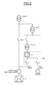
- the figure 1 illustrates a power generation system according to the state of the art and, in particular, its stage of supply and start. It comprises an alternator G for example synchronous and a GSUT group transformer.
- the alternator G comprises a rotor and a stator.
- the alternator G can operate either in an alternator mode, in which it generates electricity when the rotor is driven, or in a motor mode, for starting the turbine.
- the rotor is driven by a drive means T, for example a gas turbine, via a shaft line L, and the alternator thus supplies energy to the electrical network via the transformer.
- GSUT group The connection between the alternator G and the GSUT group transformer further comprises a GCB group circuit breaker which cuts the transmission of the current produced by the alternator.
- the rotational speed is then very important of the order several thousand revolutions per minute (from 2000 to 3000 rpm).
- the alternator is first used in motor mode so as to drive the rotor to a sufficient rotational speed VS that is to say a rotational speed so that it can be driven by the turbine.
- VS is equal to 1500 RPM.
- the electricity generation system further comprises a current converter Cg (or voltage converter of the type current source) whose function is to supply the alternator in motor mode with a current so that the rotor reaches a sufficient rotational speed.
- the current converter Cg provides an electric current whose frequency increases gradually so as to gradually increase the speed of rotation of the rotor until the sufficient rotation speed VS is obtained.
- the current converter Cg used in these applications is usually a current inverter comprising a thyristor current rectifier and an inductor.
- the current converter Cg is fed by the transformer TCg, itself powered by the transformer UAT.
- the power converter further comprises a circuit breaker represented by a switch in the figure 1 .
- the downstream part of the transformer UAT, alternator side, is secured by means of a circuit breaker between the transformers UAT and Tcg represented on the figure 1 by a switch.
- the electrical generating system also includes auxiliary equipment.
- the auxiliary equipment M is an asynchronous motor.
- the motor M requiring a power of a few megawatts is powered by the converter Cm itself powered by the transformer TCm, connected to the transformer UAT.
- the downstream part of the transformer UAT, side auxiliary equipment, is secured by means of a circuit breaker between the transformers UAT and TCm represented by a switch on the figure 1 .
- the converter Cm is, as an exemplary embodiment, a voltage converter with a power of the order of a few megawatts corresponding to the needs of the auxiliary equipment.
- this type of arrangement requires the provision of a converter dedicated to the power supply of the alternator, at the start of the turbine, and a converter for each auxiliary equipment.
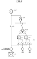
- the way rotor drive T of the figure 2 may be a gas turbine, or any other source of mechanical energy for example a micro turbine or a heat engine for example a diesel engine.
- the conversion means MC comprises a single voltage converter CT associated with a conduction means, for example an electrical wiring or a busbar, connecting the voltage converter CT (or voltage source converter) to the alternator G and auxiliary equipment M.
- the conversion means MC is powered by a supply means Tccom, for example a transformer, itself powered by the transformer UAT.
- the Tccom power supply could also be directly an electrical network.
- the conduction means comprises two branches, one connecting the voltage converter to the alternator G and the other connecting the voltage converter to the auxiliary equipment M which is, according to one embodiment, an asynchronous motor.
- Auxiliary equipment could also be a heating resistor or any other type of equipment that consumes electricity.
- the converter CT is capable of supplying the alternator in motor mode as well as the electrical equipment.
- a voltage inverter comprising a voltage rectifier which will be explained below.
- a conventional power converter such as the converter Cg described above, could not be used to power any auxiliary equipment and in particular an asynchronous motor M.
- a current converter Cg comprising for example Thyristor bridges. can only power efficiently synchronous machines.
- the alternator G is supplied with power in the motor mode so that its rotor reaches a sufficient rotation speed VS, that is to say a speed of rotation so that it can be driven by the drive means.
- each of the two branches comprises a cutoff member I1 and I2 whose state can be blocked or passing.
- the cutoff member is a circuit breaker, a disconnector, or a switch.
- the state of the cutoff member of the first branch is different from that of the cutoff member of the second branch.
- a voltage converter as described above has the advantage of being able to provide sufficient power to power alone the alternator in motor mode (of the order of ten MW). Moreover, unlike the Cg converter, it is a voltage converter (voltage source converter) so it can be used indifferently to supply synchronous or asynchronous equipment, such as for example an asynchronous motor and a synchronous alternator.
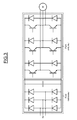
- the figure 4 illustrates an embodiment of the supply and start stage in the case where the power generation system comprises a plurality of auxiliary equipment.
- the supply means Tccom is connected to the conversion means MC which feeds a first and a second auxiliary equipment M1 and M2, which are for example two asynchronous motors.
- the conversion means MC here comprises two voltage converters CT, a first dedicated to the auxiliary equipment M1 and the alternator in motor mode, and a second dedicated to the auxiliary equipment M2 and the alternator in motor mode.
- the first and the second converter CT are connected to the alternator G, and the first and second auxiliary equipment by means of conduction.
- the conduction means may be for example busbars or electrical wiring.
- the conversion means MC may also operate in other modes.
- a third mode in which all the breaking members I1, 12, I1 'and I2' could be on or a fourth mode in which all the breaking members I1, 12, I1 'and I2' could be blocked.
- the cut-off members of the first conduction means I1 and 12 or those of the second conduction means I1 'and I2' could all be open or all closed respectively in a fifth or a sixth mode.
- a seventh advantageous mode can consist, for example, in feeding one of the auxiliary equipment M1 or M2 by means of one of the two voltage converters CT while preserving the power supply of the alternator by the other voltage converter CT ( I1 and I2 closed or 12 and I1 closed).
- the conversion means MC When the conversion means MC is in the second mode, due to the use of two voltage converters CT (or voltage source converter) in parallel, the power supplied by the two converters is added. To power the alternator in motor mode, it is therefore simply necessary that the sum of the powers of the converters is greater than the power required for the alternator in motor mode.
- the voltage converters are used separately to power the auxiliary equipment (M) and the set of voltage converters is used together to power the alternator in motor mode.
- the sum of the powers of a part of the set of converters is greater than the power required to power the alternator in motor mode. Then, only a portion of the voltage converters can be used to jointly power the alternator in motor mode.
- the power required for the starting of a shaft line is dimensioned as a function of the resistive torque, the nominal rotation speed VN and a starting time.
- a lower torque motor Cmo could also be used provided that it remains higher than the resistant torque Cr. This mode of operation corresponds to a longer start.
- the resistive torque Cr evolves approximately with the square of the speed of rotation N, and the corresponding power therefore changes with the cube of the speed of rotation.
- the engine power corresponding to the resistant torque Cr at this speed is divided by two (the multiplication 0.8 0.8 0.8 is approximately equal to at 0.5).
- This invention therefore makes it possible on the one hand to reduce the total power of the converters necessary for starting the alternator in engine mode and driving the two auxiliary equipment. It can also be used, at no additional cost (neither in terms of power converters nor financial) of a redundant starter system to start the alternator in engine mode in case of failure of a conversion module power. Finally, it allows to keep the alternator start and simultaneously supplying an auxiliary using only a portion of the voltage converters to power the alternator. For example, in the seventh mode of operation of the converter described above is simultaneously supplying an auxiliary power and starting the alternator by means of a single voltage converter for the power supply of the alternator.
- Such an arrangement is advantageous because the additional converters can be added to the power of the other voltage converters and can supply to supply auxiliary equipment or the alternator in motor mode. In other words, it provides redundancy for both systems (alternator start in engine mode and auxiliary equipment power). According to the state of the art, it would have been necessary to add a replacement module per system.
Landscapes
- Engineering & Computer Science (AREA)
- Power Engineering (AREA)
- Control Of Eletrric Generators (AREA)
Applications Claiming Priority (1)
| Application Number | Priority Date | Filing Date | Title |
|---|---|---|---|
| FR1060955A FR2969424B1 (fr) | 2010-12-21 | 2010-12-21 | Systeme de production electrique |
Publications (3)
| Publication Number | Publication Date |
|---|---|
| EP2469701A2 true EP2469701A2 (de) | 2012-06-27 |
| EP2469701A3 EP2469701A3 (de) | 2017-06-14 |
| EP2469701B1 EP2469701B1 (de) | 2020-07-29 |
Family
ID=45375229
Family Applications (1)
| Application Number | Title | Priority Date | Filing Date |
|---|---|---|---|
| EP11194396.5A Active EP2469701B1 (de) | 2010-12-21 | 2011-12-19 | Elektrisches Produktionssystem |
Country Status (3)
| Country | Link |
|---|---|
| US (2) | US20120286512A1 (de) |
| EP (1) | EP2469701B1 (de) |
| FR (1) | FR2969424B1 (de) |
Families Citing this family (4)
| Publication number | Priority date | Publication date | Assignee | Title |
|---|---|---|---|---|
| US9614457B2 (en) | 2013-10-18 | 2017-04-04 | Abb Schweiz Ag | Modular thyristor-based rectifier circuits |
| US9334749B2 (en) * | 2013-10-18 | 2016-05-10 | Abb Technology Ag | Auxiliary power system for turbine-based energy generation system |
| US9577557B2 (en) | 2013-10-18 | 2017-02-21 | Abb Schweiz Ag | Turbine-generator system with DC output |
| DE102015107934A1 (de) | 2015-05-20 | 2016-11-24 | Voith Patent Gmbh | Drehzahländerbares Antriebssystem und Verfahren zum Aufstarten und/oder Betreiben eines Drehzahländerbaren Antriebssystems |
Family Cites Families (8)
| Publication number | Priority date | Publication date | Assignee | Title |
|---|---|---|---|---|
| WO1997022176A1 (en) * | 1995-12-12 | 1997-06-19 | Solar Turbines Incorporated | Starter system for a direct drive generator |
| US6281595B1 (en) * | 2000-09-25 | 2001-08-28 | General Electric Company | Microturbine based power generation system and method |
| US6507128B2 (en) * | 2001-05-23 | 2003-01-14 | General Electric Company | Low-energy storage fast-start uninterruptible power supply system and method |
| US6847129B2 (en) * | 2001-12-07 | 2005-01-25 | Ebara Corporation | Turbine generator starting method and turbine generation system |
| JP4303152B2 (ja) * | 2004-03-22 | 2009-07-29 | 株式会社日立製作所 | 発電システムおよびその制御方法 |
| US7038329B1 (en) * | 2004-11-04 | 2006-05-02 | Utc Power, Llc | Quality power from induction generator feeding variable speed motors |
| DE102006040929B4 (de) * | 2006-08-31 | 2009-11-19 | Nordex Energy Gmbh | Verfahren zum Betrieb einer Windenergieanlage mit einem Synchrongenerator und einem Überlagerungsgetriebe |
| US20110117463A1 (en) * | 2009-11-17 | 2011-05-19 | Gm Global Technology Operation, Inc. | Battery temperature control method and assembly |
-
2010
- 2010-12-21 FR FR1060955A patent/FR2969424B1/fr active Active
-
2011
- 2011-12-19 EP EP11194396.5A patent/EP2469701B1/de active Active
- 2011-12-20 US US13/331,507 patent/US20120286512A1/en not_active Abandoned
-
2017
- 2017-05-01 US US15/583,010 patent/US20180019690A1/en not_active Abandoned
Non-Patent Citations (1)
| Title |
|---|
| None |
Also Published As
| Publication number | Publication date |
|---|---|
| FR2969424A1 (fr) | 2012-06-22 |
| US20180019690A1 (en) | 2018-01-18 |
| US20120286512A1 (en) | 2012-11-15 |
| EP2469701A3 (de) | 2017-06-14 |
| EP2469701B1 (de) | 2020-07-29 |
| FR2969424B1 (fr) | 2015-01-02 |
Similar Documents
| Publication | Publication Date | Title |
|---|---|---|
| EP2529476B1 (de) | Verfahren und vorrichtung zur steuerung einer mehrphasigen elektrischen maschine | |
| EP1362184B1 (de) | Regelungssystem für eine windkraftanlage | |
| EP3956218B1 (de) | Hybridantriebssystem und verfahren zur steuerung eines solchen systems | |
| WO2017025664A1 (fr) | Système auxiliaire de stockage et de fourniture d'énergie électrique à usages multiples intégré à une centrale de production d'électricité | |
| EP3465902B1 (de) | Bürstenloser startergenerator | |
| WO2018060591A1 (fr) | Systeme propulsif hybride pour aeronef a voilure tournante multirotor comprenant des moyens ameliores de conversion dc/ac | |
| GB2444528A (en) | Synchronising a plurality of generators | |
| EP2469701B1 (de) | Elektrisches Produktionssystem | |
| CA2597941A1 (fr) | Alimentation electrique d'equipements d'un moteur d'avion a turbine a gaz | |
| EP2588369A2 (de) | Stromversorgung für ein von einer drehauflage getragenes gerät | |
| EP4367026A1 (de) | Stromerzeugungarchitektur für hybridturbinenmotor | |
| FR2999357A1 (fr) | Chaine d'entrainement electrique d'un dispositif, et equipement de compression de gaz comprenant une telle chaine | |
| FR2990809A1 (fr) | Systeme d'alimentation en energie electrique comprenant une machine asynchrone et moteur de propulsion equipe d'un tel systeme d'alimentation en energie electrique | |
| EP2945263B1 (de) | Elektrisches unterbrechungsfreies stromversorgungssystem | |
| EP3460497B1 (de) | Vorrichtung und verfahren zum test von leistungsmodulen | |
| CA2889246C (fr) | Systeme electromecanique d'actionnement et/ou generation, comprenant une isolation electrique entre la source electrique et le consommateur | |
| EP3667898B1 (de) | Steuerung einer anzahl von aktiven leistungszellen eines drehzahlreglers | |
| EP2638632B1 (de) | Stromversorgungsschaltung für ein flugzeug mit einer asynchronmaschine | |
| EP3939153A1 (de) | System zur lieferung eines mehrphasenstroms mit konstanter frequenz aus einem synchrongenerator | |
| EP2302768B1 (de) | Vorrichtung zur Gleichstromversorgung einer Rotorspulenanordnung einer synchron umlaufenden elektrischen Maschine, und Antriebssystem, das mit solch einer Einspeisvorrichtung ausgestattet ist | |
| WO2024256085A1 (fr) | Demarreur-generateur a fonction demarreur amelioree | |
| EP4526985A1 (de) | Elektrische synchronmaschine für luftfahrzeug, entsprechende antriebsvorrichtung, entsprechendes turbotriebwerk und entsprechendes verfahren |
Legal Events
| Date | Code | Title | Description |
|---|---|---|---|
| AK | Designated contracting states |
Kind code of ref document: A2 Designated state(s): AL AT BE BG CH CY CZ DE DK EE ES FI FR GB GR HR HU IE IS IT LI LT LU LV MC MK MT NL NO PL PT RO RS SE SI SK SM TR |
|
| AX | Request for extension of the european patent |
Extension state: BA ME |
|
| PUAI | Public reference made under article 153(3) epc to a published international application that has entered the european phase |
Free format text: ORIGINAL CODE: 0009012 |
|
| PUAL | Search report despatched |
Free format text: ORIGINAL CODE: 0009013 |
|
| AK | Designated contracting states |
Kind code of ref document: A3 Designated state(s): AL AT BE BG CH CY CZ DE DK EE ES FI FR GB GR HR HU IE IS IT LI LT LU LV MC MK MT NL NO PL PT RO RS SE SI SK SM TR |
|
| AX | Request for extension of the european patent |
Extension state: BA ME |
|
| RIC1 | Information provided on ipc code assigned before grant |
Ipc: H02P 9/08 20060101AFI20170510BHEP |
|
| STAA | Information on the status of an ep patent application or granted ep patent |
Free format text: STATUS: REQUEST FOR EXAMINATION WAS MADE |
|
| 17P | Request for examination filed |
Effective date: 20171213 |
|
| STAA | Information on the status of an ep patent application or granted ep patent |
Free format text: STATUS: EXAMINATION IS IN PROGRESS |
|
| 17Q | First examination report despatched |
Effective date: 20190307 |
|
| GRAP | Despatch of communication of intention to grant a patent |
Free format text: ORIGINAL CODE: EPIDOSNIGR1 |
|
| STAA | Information on the status of an ep patent application or granted ep patent |
Free format text: STATUS: GRANT OF PATENT IS INTENDED |
|
| INTG | Intention to grant announced |
Effective date: 20200303 |
|
| GRAS | Grant fee paid |
Free format text: ORIGINAL CODE: EPIDOSNIGR3 |
|
| GRAA | (expected) grant |
Free format text: ORIGINAL CODE: 0009210 |
|
| STAA | Information on the status of an ep patent application or granted ep patent |
Free format text: STATUS: THE PATENT HAS BEEN GRANTED |
|
| AK | Designated contracting states |
Kind code of ref document: B1 Designated state(s): AL AT BE BG CH CY CZ DE DK EE ES FI FR GB GR HR HU IE IS IT LI LT LU LV MC MK MT NL NO PL PT RO RS SE SI SK SM TR |
|
| REG | Reference to a national code |
Ref country code: GB Ref legal event code: FG4D Free format text: NOT ENGLISH |
|
| REG | Reference to a national code |
Ref country code: CH Ref legal event code: EP |
|
| REG | Reference to a national code |
Ref country code: AT Ref legal event code: REF Ref document number: 1296971 Country of ref document: AT Kind code of ref document: T Effective date: 20200815 |
|
| REG | Reference to a national code |
Ref country code: IE Ref legal event code: FG4D Free format text: LANGUAGE OF EP DOCUMENT: FRENCH |
|
| REG | Reference to a national code |
Ref country code: DE Ref legal event code: R096 Ref document number: 602011067964 Country of ref document: DE |
|
| REG | Reference to a national code |
Ref country code: LT Ref legal event code: MG4D |
|
| REG | Reference to a national code |
Ref country code: NL Ref legal event code: MP Effective date: 20200729 |
|
| REG | Reference to a national code |
Ref country code: AT Ref legal event code: MK05 Ref document number: 1296971 Country of ref document: AT Kind code of ref document: T Effective date: 20200729 |
|
| PG25 | Lapsed in a contracting state [announced via postgrant information from national office to epo] |
Ref country code: NO Free format text: LAPSE BECAUSE OF FAILURE TO SUBMIT A TRANSLATION OF THE DESCRIPTION OR TO PAY THE FEE WITHIN THE PRESCRIBED TIME-LIMIT Effective date: 20201029 Ref country code: AT Free format text: LAPSE BECAUSE OF FAILURE TO SUBMIT A TRANSLATION OF THE DESCRIPTION OR TO PAY THE FEE WITHIN THE PRESCRIBED TIME-LIMIT Effective date: 20200729 Ref country code: SE Free format text: LAPSE BECAUSE OF FAILURE TO SUBMIT A TRANSLATION OF THE DESCRIPTION OR TO PAY THE FEE WITHIN THE PRESCRIBED TIME-LIMIT Effective date: 20200729 Ref country code: BG Free format text: LAPSE BECAUSE OF FAILURE TO SUBMIT A TRANSLATION OF THE DESCRIPTION OR TO PAY THE FEE WITHIN THE PRESCRIBED TIME-LIMIT Effective date: 20201029 Ref country code: ES Free format text: LAPSE BECAUSE OF FAILURE TO SUBMIT A TRANSLATION OF THE DESCRIPTION OR TO PAY THE FEE WITHIN THE PRESCRIBED TIME-LIMIT Effective date: 20200729 Ref country code: LT Free format text: LAPSE BECAUSE OF FAILURE TO SUBMIT A TRANSLATION OF THE DESCRIPTION OR TO PAY THE FEE WITHIN THE PRESCRIBED TIME-LIMIT Effective date: 20200729 Ref country code: HR Free format text: LAPSE BECAUSE OF FAILURE TO SUBMIT A TRANSLATION OF THE DESCRIPTION OR TO PAY THE FEE WITHIN THE PRESCRIBED TIME-LIMIT Effective date: 20200729 Ref country code: PT Free format text: LAPSE BECAUSE OF FAILURE TO SUBMIT A TRANSLATION OF THE DESCRIPTION OR TO PAY THE FEE WITHIN THE PRESCRIBED TIME-LIMIT Effective date: 20201130 Ref country code: FI Free format text: LAPSE BECAUSE OF FAILURE TO SUBMIT A TRANSLATION OF THE DESCRIPTION OR TO PAY THE FEE WITHIN THE PRESCRIBED TIME-LIMIT Effective date: 20200729 Ref country code: GR Free format text: LAPSE BECAUSE OF FAILURE TO SUBMIT A TRANSLATION OF THE DESCRIPTION OR TO PAY THE FEE WITHIN THE PRESCRIBED TIME-LIMIT Effective date: 20201030 |
|
| PG25 | Lapsed in a contracting state [announced via postgrant information from national office to epo] |
Ref country code: IS Free format text: LAPSE BECAUSE OF FAILURE TO SUBMIT A TRANSLATION OF THE DESCRIPTION OR TO PAY THE FEE WITHIN THE PRESCRIBED TIME-LIMIT Effective date: 20201129 Ref country code: PL Free format text: LAPSE BECAUSE OF FAILURE TO SUBMIT A TRANSLATION OF THE DESCRIPTION OR TO PAY THE FEE WITHIN THE PRESCRIBED TIME-LIMIT Effective date: 20200729 Ref country code: LV Free format text: LAPSE BECAUSE OF FAILURE TO SUBMIT A TRANSLATION OF THE DESCRIPTION OR TO PAY THE FEE WITHIN THE PRESCRIBED TIME-LIMIT Effective date: 20200729 Ref country code: RS Free format text: LAPSE BECAUSE OF FAILURE TO SUBMIT A TRANSLATION OF THE DESCRIPTION OR TO PAY THE FEE WITHIN THE PRESCRIBED TIME-LIMIT Effective date: 20200729 |
|
| PG25 | Lapsed in a contracting state [announced via postgrant information from national office to epo] |
Ref country code: NL Free format text: LAPSE BECAUSE OF FAILURE TO SUBMIT A TRANSLATION OF THE DESCRIPTION OR TO PAY THE FEE WITHIN THE PRESCRIBED TIME-LIMIT Effective date: 20200729 |
|
| PG25 | Lapsed in a contracting state [announced via postgrant information from national office to epo] |
Ref country code: RO Free format text: LAPSE BECAUSE OF FAILURE TO SUBMIT A TRANSLATION OF THE DESCRIPTION OR TO PAY THE FEE WITHIN THE PRESCRIBED TIME-LIMIT Effective date: 20200729 Ref country code: SM Free format text: LAPSE BECAUSE OF FAILURE TO SUBMIT A TRANSLATION OF THE DESCRIPTION OR TO PAY THE FEE WITHIN THE PRESCRIBED TIME-LIMIT Effective date: 20200729 Ref country code: DK Free format text: LAPSE BECAUSE OF FAILURE TO SUBMIT A TRANSLATION OF THE DESCRIPTION OR TO PAY THE FEE WITHIN THE PRESCRIBED TIME-LIMIT Effective date: 20200729 Ref country code: EE Free format text: LAPSE BECAUSE OF FAILURE TO SUBMIT A TRANSLATION OF THE DESCRIPTION OR TO PAY THE FEE WITHIN THE PRESCRIBED TIME-LIMIT Effective date: 20200729 Ref country code: CZ Free format text: LAPSE BECAUSE OF FAILURE TO SUBMIT A TRANSLATION OF THE DESCRIPTION OR TO PAY THE FEE WITHIN THE PRESCRIBED TIME-LIMIT Effective date: 20200729 Ref country code: IT Free format text: LAPSE BECAUSE OF FAILURE TO SUBMIT A TRANSLATION OF THE DESCRIPTION OR TO PAY THE FEE WITHIN THE PRESCRIBED TIME-LIMIT Effective date: 20200729 |
|
| REG | Reference to a national code |
Ref country code: DE Ref legal event code: R097 Ref document number: 602011067964 Country of ref document: DE |
|
| PG25 | Lapsed in a contracting state [announced via postgrant information from national office to epo] |
Ref country code: AL Free format text: LAPSE BECAUSE OF FAILURE TO SUBMIT A TRANSLATION OF THE DESCRIPTION OR TO PAY THE FEE WITHIN THE PRESCRIBED TIME-LIMIT Effective date: 20200729 |
|
| PLBE | No opposition filed within time limit |
Free format text: ORIGINAL CODE: 0009261 |
|
| STAA | Information on the status of an ep patent application or granted ep patent |
Free format text: STATUS: NO OPPOSITION FILED WITHIN TIME LIMIT |
|
| PG25 | Lapsed in a contracting state [announced via postgrant information from national office to epo] |
Ref country code: SK Free format text: LAPSE BECAUSE OF FAILURE TO SUBMIT A TRANSLATION OF THE DESCRIPTION OR TO PAY THE FEE WITHIN THE PRESCRIBED TIME-LIMIT Effective date: 20200729 |
|
| 26N | No opposition filed |
Effective date: 20210430 |
|
| REG | Reference to a national code |
Ref country code: CH Ref legal event code: PL |
|
| GBPC | Gb: european patent ceased through non-payment of renewal fee |
Effective date: 20201219 |
|
| PG25 | Lapsed in a contracting state [announced via postgrant information from national office to epo] |
Ref country code: MC Free format text: LAPSE BECAUSE OF FAILURE TO SUBMIT A TRANSLATION OF THE DESCRIPTION OR TO PAY THE FEE WITHIN THE PRESCRIBED TIME-LIMIT Effective date: 20200729 Ref country code: SI Free format text: LAPSE BECAUSE OF FAILURE TO SUBMIT A TRANSLATION OF THE DESCRIPTION OR TO PAY THE FEE WITHIN THE PRESCRIBED TIME-LIMIT Effective date: 20200729 |
|
| REG | Reference to a national code |
Ref country code: BE Ref legal event code: MM Effective date: 20201231 |
|
| PG25 | Lapsed in a contracting state [announced via postgrant information from national office to epo] |
Ref country code: LU Free format text: LAPSE BECAUSE OF NON-PAYMENT OF DUE FEES Effective date: 20201219 Ref country code: IE Free format text: LAPSE BECAUSE OF NON-PAYMENT OF DUE FEES Effective date: 20201219 |
|
| PG25 | Lapsed in a contracting state [announced via postgrant information from national office to epo] |
Ref country code: CH Free format text: LAPSE BECAUSE OF NON-PAYMENT OF DUE FEES Effective date: 20201231 Ref country code: GB Free format text: LAPSE BECAUSE OF NON-PAYMENT OF DUE FEES Effective date: 20201219 Ref country code: LI Free format text: LAPSE BECAUSE OF NON-PAYMENT OF DUE FEES Effective date: 20201231 |
|
| PG25 | Lapsed in a contracting state [announced via postgrant information from national office to epo] |
Ref country code: IS Free format text: LAPSE BECAUSE OF FAILURE TO SUBMIT A TRANSLATION OF THE DESCRIPTION OR TO PAY THE FEE WITHIN THE PRESCRIBED TIME-LIMIT Effective date: 20201129 Ref country code: TR Free format text: LAPSE BECAUSE OF FAILURE TO SUBMIT A TRANSLATION OF THE DESCRIPTION OR TO PAY THE FEE WITHIN THE PRESCRIBED TIME-LIMIT Effective date: 20200729 Ref country code: MT Free format text: LAPSE BECAUSE OF FAILURE TO SUBMIT A TRANSLATION OF THE DESCRIPTION OR TO PAY THE FEE WITHIN THE PRESCRIBED TIME-LIMIT Effective date: 20200729 Ref country code: CY Free format text: LAPSE BECAUSE OF FAILURE TO SUBMIT A TRANSLATION OF THE DESCRIPTION OR TO PAY THE FEE WITHIN THE PRESCRIBED TIME-LIMIT Effective date: 20200729 |
|
| PG25 | Lapsed in a contracting state [announced via postgrant information from national office to epo] |
Ref country code: MK Free format text: LAPSE BECAUSE OF FAILURE TO SUBMIT A TRANSLATION OF THE DESCRIPTION OR TO PAY THE FEE WITHIN THE PRESCRIBED TIME-LIMIT Effective date: 20200729 |
|
| PG25 | Lapsed in a contracting state [announced via postgrant information from national office to epo] |
Ref country code: BE Free format text: LAPSE BECAUSE OF NON-PAYMENT OF DUE FEES Effective date: 20201231 |
|
| PGFP | Annual fee paid to national office [announced via postgrant information from national office to epo] |
Ref country code: FR Payment date: 20231114 Year of fee payment: 13 |
|
| REG | Reference to a national code |
Ref country code: DE Ref legal event code: R081 Ref document number: 602011067964 Country of ref document: DE Owner name: GENERAL ELECTRIC TECHNOLOGY GMBH, CH Free format text: FORMER OWNER: GE ENERGY PRODUCTS FRANCE SNC, BELFORT, FR |
|
| PG25 | Lapsed in a contracting state [announced via postgrant information from national office to epo] |
Ref country code: FR Free format text: LAPSE BECAUSE OF NON-PAYMENT OF DUE FEES Effective date: 20241231 |
|
| PGFP | Annual fee paid to national office [announced via postgrant information from national office to epo] |
Ref country code: DE Payment date: 20251126 Year of fee payment: 15 |