EP2469690B1 - Method for manufacturing a cylindrical winding for slotless electrical machine - Google Patents
Method for manufacturing a cylindrical winding for slotless electrical machine Download PDFInfo
- Publication number
- EP2469690B1 EP2469690B1 EP10196906.1A EP10196906A EP2469690B1 EP 2469690 B1 EP2469690 B1 EP 2469690B1 EP 10196906 A EP10196906 A EP 10196906A EP 2469690 B1 EP2469690 B1 EP 2469690B1
- Authority
- EP
- European Patent Office
- Prior art keywords
- winding
- cylindrical
- cylindrical tube
- around
- electrical machine
- Prior art date
- Legal status (The legal status is an assumption and is not a legal conclusion. Google has not performed a legal analysis and makes no representation as to the accuracy of the status listed.)
- Active
Links
Images


Classifications
-
- H—ELECTRICITY
- H02—GENERATION; CONVERSION OR DISTRIBUTION OF ELECTRIC POWER
- H02K—DYNAMO-ELECTRIC MACHINES
- H02K15/00—Processes or apparatus specially adapted for manufacturing, assembling, maintaining or repairing of dynamo-electric machines
- H02K15/04—Processes or apparatus specially adapted for manufacturing, assembling, maintaining or repairing of dynamo-electric machines of windings prior to their mounting into the machines
- H02K15/043—Processes or apparatus specially adapted for manufacturing, assembling, maintaining or repairing of dynamo-electric machines of windings prior to their mounting into the machines winding flat conductive wires or sheets
- H02K15/0431—Concentrated windings
-
- H—ELECTRICITY
- H02—GENERATION; CONVERSION OR DISTRIBUTION OF ELECTRIC POWER
- H02K—DYNAMO-ELECTRIC MACHINES
- H02K15/00—Processes or apparatus specially adapted for manufacturing, assembling, maintaining or repairing of dynamo-electric machines
- H02K15/08—Forming windings by laying conductors into or around core parts
-
- H—ELECTRICITY
- H02—GENERATION; CONVERSION OR DISTRIBUTION OF ELECTRIC POWER
- H02K—DYNAMO-ELECTRIC MACHINES
- H02K3/00—Details of windings
- H02K3/46—Fastening of windings on the stator or rotor structure
- H02K3/47—Air-gap windings, i.e. iron-free windings
-
- Y—GENERAL TAGGING OF NEW TECHNOLOGICAL DEVELOPMENTS; GENERAL TAGGING OF CROSS-SECTIONAL TECHNOLOGIES SPANNING OVER SEVERAL SECTIONS OF THE IPC; TECHNICAL SUBJECTS COVERED BY FORMER USPC CROSS-REFERENCE ART COLLECTIONS [XRACs] AND DIGESTS
- Y10—TECHNICAL SUBJECTS COVERED BY FORMER USPC
- Y10T—TECHNICAL SUBJECTS COVERED BY FORMER US CLASSIFICATION
- Y10T29/00—Metal working
- Y10T29/49—Method of mechanical manufacture
- Y10T29/49002—Electrical device making
- Y10T29/49009—Dynamoelectric machine
-
- Y—GENERAL TAGGING OF NEW TECHNOLOGICAL DEVELOPMENTS; GENERAL TAGGING OF CROSS-SECTIONAL TECHNOLOGIES SPANNING OVER SEVERAL SECTIONS OF THE IPC; TECHNICAL SUBJECTS COVERED BY FORMER USPC CROSS-REFERENCE ART COLLECTIONS [XRACs] AND DIGESTS
- Y10—TECHNICAL SUBJECTS COVERED BY FORMER USPC
- Y10T—TECHNICAL SUBJECTS COVERED BY FORMER US CLASSIFICATION
- Y10T29/00—Metal working
- Y10T29/53—Means to assemble or disassemble
- Y10T29/5313—Means to assemble electrical device
- Y10T29/53143—Motor or generator
Definitions
- the present invention relates to a method for manufacturing a cylindrical winding for slotless electrical machine and an installation allowing to carry out this method and a winding made according said method.
- the main objective of the present invention is a method for manufacturing an electrical machine cylindrical winding automatically.
- the kind of winding is not placed in any slot of any stack of electrical steel as it is widely standardized. Wires of the coils are together placed, one next to each other, so that there is no modulation of the magnetic flux due to the presence of any tooth.
- the technology used is known as a slotless winding.
- Our invention proposes a system where it is possible to create this sort of windings with the advantage of using a technology that allows electrical machines to make high performance movements.
- This sort of electrical machines has a minimum ripple torque as there is no flux modulation due to the absence of the teeth that modulates it, there is no cogging torque, so positioning these electrical machine rotors is more easy in any angular position, provides higher torque as the rotor diameter can be bigger because the winding is placed in a crown placed outer. Eddy currents in the magnets are avoided so higher level of speeds can be reached, lower level of iron saturation exists in the lamination steel, so losses are lower and therefore the efficiency is higher.
- US 5 998 905 A discloses a method and device for manufacturing a cylindrical winding for a slotless electrical machine comprising the following steps:
- the method according to the present invention is defined in claim 1 and improves the known methods and installations.
- the winding may be the winding of stator or of a rotor with injection of a molding material or not.
- the invention relates also to an installation allowing to carry out the method and a winding made according to the present invention method.
- figure 1 we have a slotless stator 1, a winding 4 regularly disposed all around the 360° peripheral surface of a thin cylinder 6 made of a nonmagnetic material such as a fiber glass material, permanent magnets 3 disposed on the peripheral surface of a rotor 2.
- a second thin cylinder 5 made of carbon or glass fiber material is disposed around the permanent magnets 3 to hold them radially.
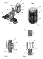
- the main devices of this installation are a winding supporting device 11 provided with means allowing to rotate the device 11 around an axes parallel to the turns of coils 41 of the winding and a device 21 designed to drive a winding head 211 according to three axis X, Y, Z.
- the winding head driving device is schematically represented but any other device allowing the winding head to move according to the three axis may be used.
- Electronic means (not represented) designed to control the winding head 211 and the winding supporting device 11 according to a predetermined program are also necessary. Said program drives devices 11 and 21 according to the kind of winding coils (overlapping coils, concentric coils, imbricated, undulated etc) the number of phases and poles of the electrical machine.
- the device 11 is mounted on a rotatable device allowing to drive the device 11 according to arrow R.
- the main elements of the device 11 are ( figures 3, 4 ) two identical cylindrical bodies 7, 8 axially movable, a first cylindrical tube 6 and a second cylindrical tube 10.
- Each cylindrical body comprises a cylindrical part 71, 81, ending at a shoulder 72, 82, followed by a conical shaped portion 73, 83.
- the conical shaped portion may be followed by another cylindrical shaped portion 74, 84 or an element allowing to attach the cylindrical body 7, 8 and to drive it axially.
- the conical portion 73, 83 is provided with a set of holes designed to receive needles 80 ( fig 5, 6 ) around which the ends of the return loops of the coils 41 are formed. The disposition of the needles in the holes depends on the kind of winding coils.
- the first cylindrical tube 6 is designed to be in abutment against the shoulders 72, 82 ( figure 7 ) when the cylindrical bodies 7, 8 are close to each other.
- the second cylindrical tube 10 ( fig 3, 4) is designed to surround the winding at the end of the winding step.
- the cylindrical tubes 6, 10 function and material depend on the kind of winding to be made. For manufacturing the winding as there are no slots, we need a support to hold the wires during the winding operation.
- the first cylindrical tube 6 is that support.
- the cylindrical tube 6 is a fiber glass cylinder with the minimum thickness, values from 0,3mm to 0,7mm are usual. The minimum value is always desired so it is not necessary to provide more quantity of magnet to cross the winding. However it cannot be a fixed value as it will also depend on the diameter of the tube to have enough rigidity and the thickness of the wires used in the winding and the fulfilling factor. As the first cylindrical tube 6 will remain inside the electrical machine, it is important to prevent overstresses that may be occurred during the working of the electrical machine i.e. heat produced by the winding. Obviously, the first cylindrical tube 6 supporting the winding must be of a non magnetic material to avoid any influence in the magnetic circuit.
- the second cylindrical tube 10 is the slotless stator made by magnetic steel laminations or magnetic powder.
- the first and second cylindrical tubes 6, 10 are two matching parts of a mold. At the end of the winding operation on the first cylindrical tube 6, the second cylindrical tube 10 is put around the winding and a molding material is injected. After cooling, the mold is removed producing a rigid cylindrical winding.
- both cylindrical tubes 6, 10 are thin non magnetic material tubes supporting the rotor winding. In this case the varnish of the winding will make a similar action as a bonding material to avoid any movement of the tubes due to centrifugal efforts. Both cylindrical tubes 6, 10 will remain inside the electrical machine.
- a commutation ring is added at the end of the method. For the molded rotor winding the commutation ring is connected to the winding before the molding operation.
- the molding material must be chosen to support high temperatures of the wires cooper without deformation of the coils.
- first cylindrical tube 6, which is a thin fiber glass tube
- the cylindrical bodies 7, 8 are moved until their shoulders 72, 82 are in abutment against the ends of first cylindrical tube 6 ( figure 4 ).
- the needles 70, 80 are placed on the conical portions 73 83.
- the winding head starts the winding operation and forms continuously (in series) the coils 41 of a first electrical phase, as seen in figure 11 and after the second electrical phase etc.
- the coils can be in series or in parallel, and connections between coils will vary.
- the program will control it to reduce them so for example if it is triangle connected the coils can be in series and the wire is not cut until the end of the winding operation (see figure 11 ) so the number of connections of the coils are reduced to a minimum, only the output cable will have to be soldered.
- the second cylindrical tube 10 which is the slotless stator is put around the formed winding ( figure 7 ).
- the needles 70, 80 are removed followed by both cylindrical bodies 7, 8 according to the arrows F2, F3 ( figure 8 ).
- the conical parts of the coils are pushed radially according the four arrows shown on figure 8 .
- the ends of the coils 41 after removal of the cylindrical bodies 7, 8 will elastically return toward their initial position that is bent toward the geometrical axis of the first cylindrical tube 6. So the first cylindrical tube 6 is hold and the same time we avoid the winding falls down from the second cylindrical tube 10.
- the fiber glass tube 6 will remain inside the electrical machine. Everything is hold by pressure.
- Concentric turns in the winding allow to avoid the formation of embossed ends as they are not crosses of the return loops. So the thickness of the winding is the same throughout.
- the present invention allows manufacturing windings with embossed ends as shown in figure 9 or of same thickness throughout as shown in figure 10 .
- the stator is longer and the performances of the machine are improved. It is also possible to manufacture constant thickness windings throughout even the turns of the coils are not concentric as explained in the pending European Patent Application EP 10195053.3 of the same Applicant.
- the method for manufacturing a molded winding is as previously explained with the following differences:
- the first and second cylindrical tubes 6, 10 are the matching parts of a mold. After completion of the winding, the second cylindrical tube 10 is put around the winding and forms with the first cylindrical tube 6 a mold in which a molding material is injected. After cooling the mold the two cylindrical tubes are removed and we have a molded winding. If the molded winding is that of a rotor before injecting the molding material a connection ring has to be added and connected to the relevant coils (see fig 12 ).
- the first cylindrical tube 6 is a thin fiber glass tube to support the winding and at the end of the winding the second cylindrical tube 10 also in fiber glass is put around the winding. Both tubes support the winding and they remain around the rotor.
- a connection ring has also to be added and connected to the relevant coils.
Landscapes
- Engineering & Computer Science (AREA)
- Manufacturing & Machinery (AREA)
- Power Engineering (AREA)
- Manufacture Of Motors, Generators (AREA)
Description
- The present invention relates to a method for manufacturing a cylindrical winding for slotless electrical machine and an installation allowing to carry out this method and a winding made according said method.
- The main objective of the present invention is a method for manufacturing an electrical machine cylindrical winding automatically. The kind of winding, is not placed in any slot of any stack of electrical steel as it is widely standardized. Wires of the coils are together placed, one next to each other, so that there is no modulation of the magnetic flux due to the presence of any tooth. The technology used is known as a slotless winding.
- The fact that in standard windings, the coils are placed into the slots of the laminated stacks makes this method not enough flexible for choosing any type of wire diameter, as the slots have a specific section, and the entrance to them is limited by the type of punch being used. It is widely commented in patent
ES 531635 - One of the difficulties of manufacturing electrical machines with windings without slots is that this technology is not often being used as it is not easy to hold wires without any tooth to keep them.
- Our invention proposes a system where it is possible to create this sort of windings with the advantage of using a technology that allows electrical machines to make high performance movements. This sort of electrical machines has a minimum ripple torque as there is no flux modulation due to the absence of the teeth that modulates it, there is no cogging torque, so positioning these electrical machine rotors is more easy in any angular position, provides higher torque as the rotor diameter can be bigger because the winding is placed in a crown placed outer. Eddy currents in the magnets are avoided so higher level of speeds can be reached, lower level of iron saturation exists in the lamination steel, so losses are lower and therefore the efficiency is higher. Some patents like
EP 0159069B1 orEP 0123347 comments also some of the great advantages of this sort of technology. - It is also explained a process to produce slotless winding technology in patent
EP 0313514B1 although in this system is not so easy to manufacture windings in big quantities as according to the present invention method. -
US 5 998 905 A discloses a method and device for manufacturing a cylindrical winding for a slotless electrical machine comprising the following steps: - i) a winding head able to move according to three axes X, Y, Z, winds continuously a wire following to a predetermined winding program around two set of needles and on the external surface of a first cylindrical tube,
- ii) after the achievement of the winding operation of all the electrical machine phases all around the 360° peripheral surface of said first cylindrical tube a second cylindrical tube is put around the achieved winding,
- iii) said two sets of needles are taken away.
-
US 2010/181860 A1 discloses a similar method and installation. - The method according to the present invention is defined in
claim 1 and improves the known methods and installations. - According to the dependent claims the winding may be the winding of stator or of a rotor with injection of a molding material or not.
- The invention relates also to an installation allowing to carry out the method and a winding made according to the present invention method.
- Preferred embodiments of the present invention will be described with reference to the attached figures.
-
Figure 1 is a side view of an electrical machine provided with a winding manufactured according to the present invention method; -
Figure 2 is a perspective view of a coil with concentrically disposed turns; -
Figure 3 is a side view of the main elements of the winding supporting device; -
Figure 4 is a side view of the elements offigure 3 in working position; -
Figure 5 is a schematically representation of the installation allowing to carry out the method of the present invention; -
Figure 6 is a perspective view of the winding supporting device; -
Figures 7 and 8 illustrate schematically the last steps of the method; -
Figures 9 and 10 show an axially cross section of an electrical machine provided with winding made according to the present method; -
Figure 10 usual representation of a winding diagram made according to the present invention; -
Figure 12 is a perspective view of a molded winding for a rotor. - In
figure 1 we have aslotless stator 1, a winding 4 regularly disposed all around the 360° peripheral surface of athin cylinder 6 made of a nonmagnetic material such as a fiber glass material,permanent magnets 3 disposed on the peripheral surface of arotor 2. In the present case a secondthin cylinder 5 made of carbon or glass fiber material is disposed around thepermanent magnets 3 to hold them radially. - Before describing the method for manufacturing the winding we will refer to the main elements of an installation represented in
figure 5 . The main devices of this installation are a winding supportingdevice 11 provided with means allowing to rotate thedevice 11 around an axes parallel to the turns ofcoils 41 of the winding and adevice 21 designed to drive a windinghead 211 according to three axis X, Y, Z. The winding head driving device is schematically represented but any other device allowing the winding head to move according to the three axis may be used. Electronic means (not represented) designed to control the windinghead 211 and the winding supportingdevice 11 according to a predetermined program are also necessary. Said program drivesdevices - The
device 11 is mounted on a rotatable device allowing to drive thedevice 11 according to arrow R. The main elements of thedevice 11 are (figures 3, 4 ) two identicalcylindrical bodies cylindrical tube 6 and a secondcylindrical tube 10. Each cylindrical body comprises acylindrical part shoulder portion shaped portion cylindrical body conical portion fig 5, 6 ) around which the ends of the return loops of thecoils 41 are formed. The disposition of the needles in the holes depends on the kind of winding coils. - The first
cylindrical tube 6 is designed to be in abutment against theshoulders 72, 82 (figure 7 ) when thecylindrical bodies
The second cylindrical tube 10 (fig 3, 4) is designed to surround the winding at the end of the winding step. - The
cylindrical tubes cylindrical tube 6 is that support. - If the winding to prepare is for a slotless stator without injection of a molding material, the
cylindrical tube 6 is a fiber glass cylinder with the minimum thickness, values from 0,3mm to 0,7mm are usual. The minimum value is always desired so it is not necessary to provide more quantity of magnet to cross the winding. However it cannot be a fixed value as it will also depend on the diameter of the tube to have enough rigidity and the thickness of the wires used in the winding and the fulfilling factor. As the firstcylindrical tube 6 will remain inside the electrical machine, it is important to prevent overstresses that may be occurred during the working of the electrical machine i.e. heat produced by the winding. Obviously, the firstcylindrical tube 6 supporting the winding must be of a non magnetic material to avoid any influence in the magnetic circuit. The secondcylindrical tube 10 is the slotless stator made by magnetic steel laminations or magnetic powder. - If the winding to prepare is for a slotless stator or rotor with injection of a molding material to rigidify the winding, the first and second
cylindrical tubes cylindrical tube 6, the secondcylindrical tube 10 is put around the winding and a molding material is injected. After cooling, the mold is removed producing a rigid cylindrical winding. - If the winding to prepare is for a slotless rotor without injection of a molding material, both
cylindrical tubes cylindrical tubes - The molding material must be chosen to support high temperatures of the wires cooper without deformation of the coils.
- We will describe now the method with reference to
figures 3 to 8 relating to the winding of a slotless stator. The description andfigures 5, 6 relates to the manufacturing of a winding whose turns of the coils are placed concentrically (seefigure 2 ). Any other kind of winding may be manufactured according to the present invention, the main difference being theneedles head 211 movements and the winding supportingdevice 11 rotation movements. - At the beginning the first
cylindrical tube 6, which is a thin fiber glass tube, is put in the space between thecylindrical bodies cylindrical bodies shoulders figure 4 ). Theneedles conical portions 73 83. The winding head starts the winding operation and forms continuously (in series) thecoils 41 of a first electrical phase, as seen infigure 11 and after the second electrical phase etc. Depending on the type of winding, i.e. WYE (star) connected or triangle, the coils can be in series or in parallel, and connections between coils will vary. The program will control it to reduce them so for example if it is triangle connected the coils can be in series and the wire is not cut until the end of the winding operation (seefigure 11 ) so the number of connections of the coils are reduced to a minimum, only the output cable will have to be soldered. - In the described example we place the wires of the coils concentrically so the space used is optimized, as no crosses of the wires may appear that could create problems of thickness or damaging the wires. In
figure 2 it is shown how the wires of the coils are placed. This forces the windinghead 211 to be sensitive enough for placing the wires correctly in three dimensions as deepness is also relevant. For this reason thedevice 21 is able to work according to three axes X, Y and Z (fig. 5 ) to place the wire correctly and to monitor the winding supportingdevice 11 where thecoils 41 are being placed. The installation is able to wind all kind of windings, overlapped, concentrated, multiphase and even imbricated or undulated brushed type. - After completion of the winding operation the second
cylindrical tube 10, which is the slotless stator is put around the formed winding (figure 7 ). Theneedles cylindrical bodies figure 8 ). When removingcylindrical tubes figure 8 . The ends of thecoils 41 after removal of thecylindrical bodies cylindrical tube 6. So the firstcylindrical tube 6 is hold and the same time we avoid the winding falls down from the secondcylindrical tube 10. Thefiber glass tube 6 will remain inside the electrical machine. Everything is hold by pressure. - Concentric turns in the winding allow to avoid the formation of embossed ends as they are not crosses of the return loops. So the thickness of the winding is the same throughout. The present invention allows manufacturing windings with embossed ends as shown in
figure 9 or of same thickness throughout as shown infigure 10 . In the second case the stator is longer and the performances of the machine are improved. It is also possible to manufacture constant thickness windings throughout even the turns of the coils are not concentric as explained in the pending European Patent ApplicationEP 10195053.3 - Windings where the coils are injected one to one and further making the appropriate connections cannot be compared with the present invention.
- The method for manufacturing a molded winding is as previously explained with the following differences: The first and second
cylindrical tubes cylindrical tube 10 is put around the winding and forms with the first cylindrical tube 6 a mold in which a molding material is injected. After cooling the mold the two cylindrical tubes are removed and we have a molded winding. If the molded winding is that of a rotor before injecting the molding material a connection ring has to be added and connected to the relevant coils (seefig 12 ). - If the winding is a no molded winding for a rotor the first
cylindrical tube 6 is a thin fiber glass tube to support the winding and at the end of the winding the secondcylindrical tube 10 also in fiber glass is put around the winding. Both tubes support the winding and they remain around the rotor. A connection ring has also to be added and connected to the relevant coils.
Claims (8)
- Method for manufacturing a cylindrical winding (4) for a slotless electrical machine according to the following steps:a) a winding head (211) able to move according to three axes X, Y, Z, winds continuously a wire following to a predetermined winding program around two set of needles (70,80) and on the external surface of a first cylindrical tube (6), said needles (70,80) being located on the conical shaped end (73,83) surfaces of two identical cylindrical bodies (7,8) axially juxtaposed and axially and rotatable movable, said cylindrical bodies (7,8) being partially located inside said first cylindrical tube (6),b) after the achievement of the winding operation of all the electrical machine phases all around the 360° peripheral surface of said first cylindrical tube (6) a second cylindrical tube (10) is put around the achieved winding (4);c)said two sets of needles (70,80) are taken away and the two cylindrical bodies (7,8) are axially moved away.
- A method according to claim 1, characterized in that said first and second cylindrical tubes (6,10) are two matching parts of mold in that after the second cylindrical tube (10) is put around the achieved winding (4) so the formed mold is filled with a molding material and in that after cooling the mold is removed producing a rigid cylindrical winding.
- A method according to claim 1, characterized in that said winding (4) is a stator winding, said first cylindrical tube (6) supporting the winding is made in a no magnetic material such as fiber glass and in that the second cylindrical tube (10) is a slotless stator made of magnetic material such as stack of steel lamination or of magnetic powder.
- A method according to claim 1, characterized in that said winding (4) is a rotor winding, said first and second cylindrical tubes (6,10) supporting the winding are made of a non magnetic material such as fiber glass and in that at the end of the method a commutation ring (42) is connected to the winding (4).
- A method according to claim 2, characterized in that said winding (4) is a rotor winding, and in that at the end of the method a commutation ring (42) is connected to the winding.
- A method according to one of claims 1 to 5, characterized in that the wires forming each coil of the winding (4) are disposed concentrically to avoid crosses of the wires at the return loops of the turns of the coils and allowing to obtain a winding having the same thickness throughout.
- Installation for carrying out the method according to claim 1, comprising a device (21) provided with a winding head (211) designed to move according to three different axes X, Y, Z, a winding supporting device (11) rotatable around an axis parallel to the turns of the winding (4) comprising a first cylindrical tube (6) and a second cylindrical tube (10) axially movable and designed to be around the cylindrical winding (4) and control electronic means designed to control the winding head and the winding supporting device rotation movements, characterized in that it comprises two axially juxtaposed cylindrical bodies (7,8) designed to move axially provided at their remote ends with a shoulder (72,82) followed by a conical shape (73,83) portion, said conical shaped portions being provided with means designed to hold a set of needles (70,80) and in that said first cylindrical tube (6) is designed to be in abutment between said shoulders (72,82) when both cylindrical bodies are close.
- Cylidrical winding for electrical machine made according to the method of one of the claims 1 to 6.
Priority Applications (4)
| Application Number | Priority Date | Filing Date | Title |
|---|---|---|---|
| ES10196906.1T ES2441739T3 (en) | 2010-12-23 | 2010-12-23 | Method to manufacture a cylindrical winding for electric machine without grooves |
| EP10196906.1A EP2469690B1 (en) | 2010-12-23 | 2010-12-23 | Method for manufacturing a cylindrical winding for slotless electrical machine |
| US13/329,843 US8919685B2 (en) | 2010-12-23 | 2011-12-19 | Method for manufacturing a cylindrical winding for slotless electrical machine |
| JP2011281054A JP5975638B2 (en) | 2010-12-23 | 2011-12-22 | Method for manufacturing cylindrical windings for slotless electrical machines |
Applications Claiming Priority (1)
| Application Number | Priority Date | Filing Date | Title |
|---|---|---|---|
| EP10196906.1A EP2469690B1 (en) | 2010-12-23 | 2010-12-23 | Method for manufacturing a cylindrical winding for slotless electrical machine |
Publications (2)
| Publication Number | Publication Date |
|---|---|
| EP2469690A1 EP2469690A1 (en) | 2012-06-27 |
| EP2469690B1 true EP2469690B1 (en) | 2013-10-16 |
Family
ID=43857849
Family Applications (1)
| Application Number | Title | Priority Date | Filing Date |
|---|---|---|---|
| EP10196906.1A Active EP2469690B1 (en) | 2010-12-23 | 2010-12-23 | Method for manufacturing a cylindrical winding for slotless electrical machine |
Country Status (4)
| Country | Link |
|---|---|
| US (1) | US8919685B2 (en) |
| EP (1) | EP2469690B1 (en) |
| JP (1) | JP5975638B2 (en) |
| ES (1) | ES2441739T3 (en) |
Families Citing this family (14)
| Publication number | Priority date | Publication date | Assignee | Title |
|---|---|---|---|---|
| US8572838B2 (en) | 2011-03-02 | 2013-11-05 | Honeywell International Inc. | Methods for fabricating high temperature electromagnetic coil assemblies |
| US8860541B2 (en) | 2011-10-18 | 2014-10-14 | Honeywell International Inc. | Electromagnetic coil assemblies having braided lead wires and methods for the manufacture thereof |
| US8754735B2 (en) | 2012-04-30 | 2014-06-17 | Honeywell International Inc. | High temperature electromagnetic coil assemblies including braided lead wires and methods for the fabrication thereof |
| US9076581B2 (en) | 2012-04-30 | 2015-07-07 | Honeywell International Inc. | Method for manufacturing high temperature electromagnetic coil assemblies including brazed braided lead wires |
| JP5930536B2 (en) * | 2012-07-03 | 2016-06-08 | 日特エンジニアリング株式会社 | Winding device and winding method |
| US9027228B2 (en) | 2012-11-29 | 2015-05-12 | Honeywell International Inc. | Method for manufacturing electromagnetic coil assemblies |
| US9722464B2 (en) | 2013-03-13 | 2017-08-01 | Honeywell International Inc. | Gas turbine engine actuation systems including high temperature actuators and methods for the manufacture thereof |
| CN106230207B (en) * | 2016-08-12 | 2019-01-18 | 杭州弘弈智能科技有限公司 | A kind of lower wire passing device of electric motor internal stator coiling |
| EP3528372A1 (en) * | 2018-02-19 | 2019-08-21 | Siemens Gamesa Renewable Energy A/S | Formation of stator coils for use in concentrated winding electrical machine |
| US11041252B2 (en) | 2018-03-22 | 2021-06-22 | Honeywell International Inc. | Deposition of wear resistant nickel-tungsten plating systems |
| KR102154040B1 (en) * | 2018-12-24 | 2020-09-09 | 주식회사 로텍 | Winding jig and manufacturining method of coil for slotless motor and coil using the same |
| US11641142B2 (en) | 2020-10-16 | 2023-05-02 | Delta Electronics, Inc. | Stator and winding assembly thereof |
| CN114374288B (en) * | 2020-10-16 | 2024-01-09 | 台达电子工业股份有限公司 | Stator and its winding components |
| GB2615991B (en) | 2022-01-19 | 2024-02-21 | Eta Green Power Ltd | A method of manufacturing a stator for a slotless electric motor |
Family Cites Families (19)
| Publication number | Priority date | Publication date | Assignee | Title |
|---|---|---|---|---|
| JPS5120501A (en) * | 1974-08-09 | 1976-02-18 | Hitachi Ltd | Denkishokoiruno seizohoho |
| JPS5721243U (en) * | 1980-07-10 | 1982-02-03 | ||
| JPS5762761A (en) * | 1980-09-30 | 1982-04-15 | Matsushita Electric Works Ltd | Manufacture of coreless type armature |
| JPS58112445A (en) * | 1981-12-26 | 1983-07-04 | Toshiba Corp | Winding device for coreless armature |
| JPS5996853A (en) * | 1982-11-25 | 1984-06-04 | Entatsuku Kk | Method for manufacturing bottomed cup cylindrical winding body and apparatus for manufacturing the same |
| IT1198555B (en) | 1983-04-15 | 1988-12-21 | Giampiero Tassinario | ARMATURE MANUFACTURING PROCESS FOR AN ELECTRONICALLY COMMUTED ELECTRIC MOTOR AND ARMATURE MANUFACTURED ACCORDING TO THIS PROCEDURE |
| IT1198556B (en) | 1983-04-15 | 1988-12-21 | Giampiero Tassinario | DIRECT CURRENT MOTOR WITHOUT ELECTRONICALLY COMMUTED MANIFOLD |
| DE3581823D1 (en) | 1984-04-11 | 1991-04-04 | Mavilor Syst Sa | COLLECTORLESS, ELECTRONICALLY COMMUTED ELECTRIC MOTOR. |
| JPH088762B2 (en) * | 1986-08-27 | 1996-01-29 | 三工機器株式会社 | Coil shaping jig |
| CH675331A5 (en) | 1987-10-21 | 1990-09-14 | Mavilor Syst Sa | |
| US5606791A (en) * | 1993-09-17 | 1997-03-04 | Fougere; Richard J. | Method of making a slotless electric motor or transducer |
| WO1999018207A1 (en) | 1997-10-03 | 1999-04-15 | Osiris Therapeutics, Inc. | Human hox c10 and polynucleotides encoding |
| JPH11234939A (en) * | 1998-02-09 | 1999-08-27 | Japan Servo Co Ltd | Coil bobbin device |
| AU2002230503A1 (en) * | 2000-11-28 | 2002-06-11 | Centaur Motor Systems, Llc | Slotless stator manufacturing apparatus and method |
| US6991194B2 (en) * | 2002-06-17 | 2006-01-31 | Axis Usa, Inc. | Needle solution for coil stratification |
| JP2004336969A (en) * | 2003-05-12 | 2004-11-25 | Fuji Heavy Ind Ltd | Casting equipment |
| JP2008043101A (en) * | 2006-08-08 | 2008-02-21 | Toyota Motor Corp | Rotating motor manufacturing apparatus and rotating motor manufacturing method |
| JP2009183043A (en) * | 2008-01-30 | 2009-08-13 | Tamagawa Seiki Co Ltd | Motor stator assembly jig and motor stator assembly method |
| US7913375B2 (en) * | 2009-01-19 | 2011-03-29 | Sergey Pulnikov | Method for making electrical windings for electrical machines and winding obtained by said method |
-
2010
- 2010-12-23 EP EP10196906.1A patent/EP2469690B1/en active Active
- 2010-12-23 ES ES10196906.1T patent/ES2441739T3/en active Active
-
2011
- 2011-12-19 US US13/329,843 patent/US8919685B2/en active Active
- 2011-12-22 JP JP2011281054A patent/JP5975638B2/en active Active
Also Published As
| Publication number | Publication date |
|---|---|
| US20120175991A1 (en) | 2012-07-12 |
| US8919685B2 (en) | 2014-12-30 |
| ES2441739T3 (en) | 2014-02-06 |
| JP2012135202A (en) | 2012-07-12 |
| EP2469690A1 (en) | 2012-06-27 |
| JP5975638B2 (en) | 2016-08-23 |
Similar Documents
| Publication | Publication Date | Title |
|---|---|---|
| US8919685B2 (en) | Method for manufacturing a cylindrical winding for slotless electrical machine | |
| US7348706B2 (en) | Stator assembly for an electric machine and method of manufacturing the same | |
| EP2120313B1 (en) | Electrical motor and method for manufacturing the same | |
| EP3142235B1 (en) | Stator-manufacturing method and stator | |
| CN104052200B (en) | Motor and component and associated component for being installed to electric connector on stator | |
| US20030168926A1 (en) | Electrical machine construction using axially inserted teeth in a stator ring or armature | |
| US20020140312A1 (en) | Method for manufacturing an armature of an internal rotor type electric machine and the armature manufactured by such method | |
| US6876118B2 (en) | Abduction-type motor and fabrication method of motor stator thereof | |
| WO2011118357A1 (en) | Electromagnet for stator and method of manufacturing electromagnet for stator | |
| CN103516072A (en) | Arrangement of coil wires in a rotor of an electric motor | |
| CN110011436A (en) | A combined permanent magnet brushless motor stator and manufacturing method | |
| JPWO2020174817A1 (en) | Rotating electric machine stator, rotating electric machine, manufacturing method of rotating electric machine stator, and manufacturing method of rotating electric machine | |
| EP3528372A1 (en) | Formation of stator coils for use in concentrated winding electrical machine | |
| CN101018002A (en) | Small three-phase high-performance square wave permanent magnetic DC low-speed brushless motor | |
| JP6057777B2 (en) | Stator, hermetic compressor and rotary machine including the stator, and mold | |
| JP2012170295A (en) | Stator of rotary electric machine and method of manufacturing the same | |
| CN107078611A (en) | Rotor or stator with plug-in flat winding heads | |
| WO2021035862A1 (en) | Stator assembly, electric motor, compressor, and refrigeration device | |
| WO2020170422A1 (en) | Stator, motor, and compressor | |
| CN107925321B (en) | Manufacturing method of armature | |
| CN103051116B (en) | Manufacturing method and special press fitting apparatus of partitioned stator of servo motor of sewing machine | |
| WO2005114817A1 (en) | Multiple winding coil shapes for increased slot fill | |
| CN201403038Y (en) | DC permanent-magnet brushless motor | |
| CN206461447U (en) | A kind of assembly type stator motor | |
| JP2007037288A (en) | Rotor for permanent magnet type rotating electrical machine and method for manufacturing the same |
Legal Events
| Date | Code | Title | Description |
|---|---|---|---|
| AK | Designated contracting states |
Kind code of ref document: A1 Designated state(s): AL AT BE BG CH CY CZ DE DK EE ES FI FR GB GR HR HU IE IS IT LI LT LU LV MC MK MT NL NO PL PT RO RS SE SI SK SM TR |
|
| AX | Request for extension of the european patent |
Extension state: BA ME |
|
| PUAI | Public reference made under article 153(3) epc to a published international application that has entered the european phase |
Free format text: ORIGINAL CODE: 0009012 |
|
| 17P | Request for examination filed |
Effective date: 20121205 |
|
| GRAP | Despatch of communication of intention to grant a patent |
Free format text: ORIGINAL CODE: EPIDOSNIGR1 |
|
| INTG | Intention to grant announced |
Effective date: 20130508 |
|
| RIN1 | Information on inventor provided before grant (corrected) |
Inventor name: GALCERAN, JOAQUIM Inventor name: TASSINARIO, GIAMPIERO Inventor name: FLOTATS, IVAN Inventor name: CRUELLAS, FRANCESC |
|
| GRAS | Grant fee paid |
Free format text: ORIGINAL CODE: EPIDOSNIGR3 |
|
| GRAP | Despatch of communication of intention to grant a patent |
Free format text: ORIGINAL CODE: EPIDOSNIGR1 |
|
| GRAA | (expected) grant |
Free format text: ORIGINAL CODE: 0009210 |
|
| INTG | Intention to grant announced |
Effective date: 20130902 |
|
| AK | Designated contracting states |
Kind code of ref document: B1 Designated state(s): AL AT BE BG CH CY CZ DE DK EE ES FI FR GB GR HR HU IE IS IT LI LT LU LV MC MK MT NL NO PL PT RO RS SE SI SK SM TR |
|
| REG | Reference to a national code |
Ref country code: GB Ref legal event code: FG4D |
|
| REG | Reference to a national code |
Ref country code: CH Ref legal event code: EP Ref country code: CH Ref legal event code: NV Representative=s name: BUGNION S.A., CH |
|
| REG | Reference to a national code |
Ref country code: IE Ref legal event code: FG4D |
|
| REG | Reference to a national code |
Ref country code: AT Ref legal event code: REF Ref document number: 636907 Country of ref document: AT Kind code of ref document: T Effective date: 20131115 |
|
| REG | Reference to a national code |
Ref country code: DE Ref legal event code: R096 Ref document number: 602010010945 Country of ref document: DE Effective date: 20131212 |
|
| REG | Reference to a national code |
Ref country code: NL Ref legal event code: T3 |
|
| REG | Reference to a national code |
Ref country code: SE Ref legal event code: TRGR |
|
| REG | Reference to a national code |
Ref country code: ES Ref legal event code: FG2A Ref document number: 2441739 Country of ref document: ES Kind code of ref document: T3 Effective date: 20140206 |
|
| REG | Reference to a national code |
Ref country code: AT Ref legal event code: MK05 Ref document number: 636907 Country of ref document: AT Kind code of ref document: T Effective date: 20131016 |
|
| REG | Reference to a national code |
Ref country code: LT Ref legal event code: MG4D |
|
| PG25 | Lapsed in a contracting state [announced via postgrant information from national office to epo] |
Ref country code: FI Free format text: LAPSE BECAUSE OF FAILURE TO SUBMIT A TRANSLATION OF THE DESCRIPTION OR TO PAY THE FEE WITHIN THE PRESCRIBED TIME-LIMIT Effective date: 20131016 Ref country code: NO Free format text: LAPSE BECAUSE OF FAILURE TO SUBMIT A TRANSLATION OF THE DESCRIPTION OR TO PAY THE FEE WITHIN THE PRESCRIBED TIME-LIMIT Effective date: 20140116 Ref country code: IS Free format text: LAPSE BECAUSE OF FAILURE TO SUBMIT A TRANSLATION OF THE DESCRIPTION OR TO PAY THE FEE WITHIN THE PRESCRIBED TIME-LIMIT Effective date: 20140216 Ref country code: LT Free format text: LAPSE BECAUSE OF FAILURE TO SUBMIT A TRANSLATION OF THE DESCRIPTION OR TO PAY THE FEE WITHIN THE PRESCRIBED TIME-LIMIT Effective date: 20131016 Ref country code: HR Free format text: LAPSE BECAUSE OF FAILURE TO SUBMIT A TRANSLATION OF THE DESCRIPTION OR TO PAY THE FEE WITHIN THE PRESCRIBED TIME-LIMIT Effective date: 20131016 |
|
| PG25 | Lapsed in a contracting state [announced via postgrant information from national office to epo] |
Ref country code: LV Free format text: LAPSE BECAUSE OF FAILURE TO SUBMIT A TRANSLATION OF THE DESCRIPTION OR TO PAY THE FEE WITHIN THE PRESCRIBED TIME-LIMIT Effective date: 20131016 Ref country code: CY Free format text: LAPSE BECAUSE OF FAILURE TO SUBMIT A TRANSLATION OF THE DESCRIPTION OR TO PAY THE FEE WITHIN THE PRESCRIBED TIME-LIMIT Effective date: 20131016 Ref country code: RS Free format text: LAPSE BECAUSE OF FAILURE TO SUBMIT A TRANSLATION OF THE DESCRIPTION OR TO PAY THE FEE WITHIN THE PRESCRIBED TIME-LIMIT Effective date: 20131016 Ref country code: AT Free format text: LAPSE BECAUSE OF FAILURE TO SUBMIT A TRANSLATION OF THE DESCRIPTION OR TO PAY THE FEE WITHIN THE PRESCRIBED TIME-LIMIT Effective date: 20131016 |
|
| PG25 | Lapsed in a contracting state [announced via postgrant information from national office to epo] |
Ref country code: PT Free format text: LAPSE BECAUSE OF FAILURE TO SUBMIT A TRANSLATION OF THE DESCRIPTION OR TO PAY THE FEE WITHIN THE PRESCRIBED TIME-LIMIT Effective date: 20140217 |
|
| REG | Reference to a national code |
Ref country code: DE Ref legal event code: R097 Ref document number: 602010010945 Country of ref document: DE |
|
| PG25 | Lapsed in a contracting state [announced via postgrant information from national office to epo] |
Ref country code: EE Free format text: LAPSE BECAUSE OF FAILURE TO SUBMIT A TRANSLATION OF THE DESCRIPTION OR TO PAY THE FEE WITHIN THE PRESCRIBED TIME-LIMIT Effective date: 20131016 |
|
| PLBE | No opposition filed within time limit |
Free format text: ORIGINAL CODE: 0009261 |
|
| STAA | Information on the status of an ep patent application or granted ep patent |
Free format text: STATUS: NO OPPOSITION FILED WITHIN TIME LIMIT |
|
| PG25 | Lapsed in a contracting state [announced via postgrant information from national office to epo] |
Ref country code: SK Free format text: LAPSE BECAUSE OF FAILURE TO SUBMIT A TRANSLATION OF THE DESCRIPTION OR TO PAY THE FEE WITHIN THE PRESCRIBED TIME-LIMIT Effective date: 20131016 Ref country code: PL Free format text: LAPSE BECAUSE OF FAILURE TO SUBMIT A TRANSLATION OF THE DESCRIPTION OR TO PAY THE FEE WITHIN THE PRESCRIBED TIME-LIMIT Effective date: 20131016 Ref country code: RO Free format text: LAPSE BECAUSE OF FAILURE TO SUBMIT A TRANSLATION OF THE DESCRIPTION OR TO PAY THE FEE WITHIN THE PRESCRIBED TIME-LIMIT Effective date: 20131016 |
|
| 26N | No opposition filed |
Effective date: 20140717 |
|
| REG | Reference to a national code |
Ref country code: IE Ref legal event code: MM4A |
|
| PG25 | Lapsed in a contracting state [announced via postgrant information from national office to epo] |
Ref country code: DK Free format text: LAPSE BECAUSE OF FAILURE TO SUBMIT A TRANSLATION OF THE DESCRIPTION OR TO PAY THE FEE WITHIN THE PRESCRIBED TIME-LIMIT Effective date: 20131016 |
|
| REG | Reference to a national code |
Ref country code: DE Ref legal event code: R097 Ref document number: 602010010945 Country of ref document: DE Effective date: 20140717 |
|
| PG25 | Lapsed in a contracting state [announced via postgrant information from national office to epo] |
Ref country code: IE Free format text: LAPSE BECAUSE OF NON-PAYMENT OF DUE FEES Effective date: 20131223 |
|
| PG25 | Lapsed in a contracting state [announced via postgrant information from national office to epo] |
Ref country code: SI Free format text: LAPSE BECAUSE OF FAILURE TO SUBMIT A TRANSLATION OF THE DESCRIPTION OR TO PAY THE FEE WITHIN THE PRESCRIBED TIME-LIMIT Effective date: 20131016 |
|
| PG25 | Lapsed in a contracting state [announced via postgrant information from national office to epo] |
Ref country code: MC Free format text: LAPSE BECAUSE OF FAILURE TO SUBMIT A TRANSLATION OF THE DESCRIPTION OR TO PAY THE FEE WITHIN THE PRESCRIBED TIME-LIMIT Effective date: 20131016 |
|
| PG25 | Lapsed in a contracting state [announced via postgrant information from national office to epo] |
Ref country code: SM Free format text: LAPSE BECAUSE OF FAILURE TO SUBMIT A TRANSLATION OF THE DESCRIPTION OR TO PAY THE FEE WITHIN THE PRESCRIBED TIME-LIMIT Effective date: 20131016 |
|
| PG25 | Lapsed in a contracting state [announced via postgrant information from national office to epo] |
Ref country code: HU Free format text: LAPSE BECAUSE OF FAILURE TO SUBMIT A TRANSLATION OF THE DESCRIPTION OR TO PAY THE FEE WITHIN THE PRESCRIBED TIME-LIMIT; INVALID AB INITIO Effective date: 20101223 Ref country code: BG Free format text: LAPSE BECAUSE OF FAILURE TO SUBMIT A TRANSLATION OF THE DESCRIPTION OR TO PAY THE FEE WITHIN THE PRESCRIBED TIME-LIMIT Effective date: 20131016 Ref country code: MK Free format text: LAPSE BECAUSE OF FAILURE TO SUBMIT A TRANSLATION OF THE DESCRIPTION OR TO PAY THE FEE WITHIN THE PRESCRIBED TIME-LIMIT Effective date: 20131016 |
|
| PG25 | Lapsed in a contracting state [announced via postgrant information from national office to epo] |
Ref country code: GR Free format text: LAPSE BECAUSE OF NON-PAYMENT OF DUE FEES Effective date: 20131016 Ref country code: MT Free format text: LAPSE BECAUSE OF FAILURE TO SUBMIT A TRANSLATION OF THE DESCRIPTION OR TO PAY THE FEE WITHIN THE PRESCRIBED TIME-LIMIT Effective date: 20131016 |
|
| REG | Reference to a national code |
Ref country code: FR Ref legal event code: PLFP Year of fee payment: 6 |
|
| PG25 | Lapsed in a contracting state [announced via postgrant information from national office to epo] |
Ref country code: GR Free format text: LAPSE BECAUSE OF FAILURE TO SUBMIT A TRANSLATION OF THE DESCRIPTION OR TO PAY THE FEE WITHIN THE PRESCRIBED TIME-LIMIT Effective date: 20140117 |
|
| PG25 | Lapsed in a contracting state [announced via postgrant information from national office to epo] |
Ref country code: TR Free format text: LAPSE BECAUSE OF FAILURE TO SUBMIT A TRANSLATION OF THE DESCRIPTION OR TO PAY THE FEE WITHIN THE PRESCRIBED TIME-LIMIT Effective date: 20131016 |
|
| REG | Reference to a national code |
Ref country code: DE Ref legal event code: R082 Ref document number: 602010010945 Country of ref document: DE Representative=s name: PRINZ & PARTNER MBB PATENTANWAELTE RECHTSANWAE, DE |
|
| REG | Reference to a national code |
Ref country code: FR Ref legal event code: PLFP Year of fee payment: 7 |
|
| REG | Reference to a national code |
Ref country code: FR Ref legal event code: PLFP Year of fee payment: 8 |
|
| PG25 | Lapsed in a contracting state [announced via postgrant information from national office to epo] |
Ref country code: AL Free format text: LAPSE BECAUSE OF FAILURE TO SUBMIT A TRANSLATION OF THE DESCRIPTION OR TO PAY THE FEE WITHIN THE PRESCRIBED TIME-LIMIT Effective date: 20131016 |
|
| PGFP | Annual fee paid to national office [announced via postgrant information from national office to epo] |
Ref country code: LU Payment date: 20251127 Year of fee payment: 16 Ref country code: NL Payment date: 20251127 Year of fee payment: 16 |
|
| REG | Reference to a national code |
Ref country code: CH Ref legal event code: U11 Free format text: ST27 STATUS EVENT CODE: U-0-0-U10-U11 (AS PROVIDED BY THE NATIONAL OFFICE) Effective date: 20260101 |
|
| PGFP | Annual fee paid to national office [announced via postgrant information from national office to epo] |
Ref country code: DE Payment date: 20251127 Year of fee payment: 16 |
|
| PGFP | Annual fee paid to national office [announced via postgrant information from national office to epo] |
Ref country code: GB Payment date: 20251125 Year of fee payment: 16 |
|
| PGFP | Annual fee paid to national office [announced via postgrant information from national office to epo] |
Ref country code: IT Payment date: 20251209 Year of fee payment: 16 |
|
| PGFP | Annual fee paid to national office [announced via postgrant information from national office to epo] |
Ref country code: FR Payment date: 20251125 Year of fee payment: 16 |
|
| PGFP | Annual fee paid to national office [announced via postgrant information from national office to epo] |
Ref country code: BE Payment date: 20251226 Year of fee payment: 16 |
|
| PGFP | Annual fee paid to national office [announced via postgrant information from national office to epo] |
Ref country code: SE Payment date: 20251218 Year of fee payment: 16 |
|
| PGFP | Annual fee paid to national office [announced via postgrant information from national office to epo] |
Ref country code: CZ Payment date: 20251223 Year of fee payment: 16 |
|
| PGFP | Annual fee paid to national office [announced via postgrant information from national office to epo] |
Ref country code: ES Payment date: 20260112 Year of fee payment: 16 |
|
| PGFP | Annual fee paid to national office [announced via postgrant information from national office to epo] |
Ref country code: CH Payment date: 20260101 Year of fee payment: 16 |