EP2469662A1 - Self-Orienting Electrical Connector - Google Patents
Self-Orienting Electrical Connector Download PDFInfo
- Publication number
- EP2469662A1 EP2469662A1 EP10196424A EP10196424A EP2469662A1 EP 2469662 A1 EP2469662 A1 EP 2469662A1 EP 10196424 A EP10196424 A EP 10196424A EP 10196424 A EP10196424 A EP 10196424A EP 2469662 A1 EP2469662 A1 EP 2469662A1
- Authority
- EP
- European Patent Office
- Prior art keywords
- electrical connector
- electrical
- complementary
- connector
- connecting side
- Prior art date
- Legal status (The legal status is an assumption and is not a legal conclusion. Google has not performed a legal analysis and makes no representation as to the accuracy of the status listed.)
- Granted
Links
Images





Classifications
-
- H—ELECTRICITY
- H01—ELECTRIC ELEMENTS
- H01R—ELECTRICALLY-CONDUCTIVE CONNECTIONS; STRUCTURAL ASSOCIATIONS OF A PLURALITY OF MUTUALLY-INSULATED ELECTRICAL CONNECTING ELEMENTS; COUPLING DEVICES; CURRENT COLLECTORS
- H01R13/00—Details of coupling devices of the kinds covered by groups H01R12/70 or H01R24/00 - H01R33/00
- H01R13/62—Means for facilitating engagement or disengagement of coupling parts or for holding them in engagement
- H01R13/6205—Two-part coupling devices held in engagement by a magnet
-
- H—ELECTRICITY
- H01—ELECTRIC ELEMENTS
- H01R—ELECTRICALLY-CONDUCTIVE CONNECTIONS; STRUCTURAL ASSOCIATIONS OF A PLURALITY OF MUTUALLY-INSULATED ELECTRICAL CONNECTING ELEMENTS; COUPLING DEVICES; CURRENT COLLECTORS
- H01R13/00—Details of coupling devices of the kinds covered by groups H01R12/70 or H01R24/00 - H01R33/00
- H01R13/64—Means for preventing incorrect coupling
Definitions
- the present disclosure relates to electrical connectors and more particularly to a self orienting electrical connector.
- USB Universal Serial Bus
- USB connectors and other data connectors typically include a female connector installed on an electronic device which receives a corresponding male connector which may be installed, for example, on a data cable.
- the connectors Since the male connector is physically inserted into the female connector, the connectors may become damaged if the male connector is accidentally impacted. Furthermore, in order to physically insert the male connector into the female connector, the connectors must be properly aligned. Aligning the connectors is sometimes difficult where one of the connectors is obscured. For example, USB connectors are often provided on a back-side of desktop computers. In such cases, users are sometimes faced with the difficult task of inserting a USB data cable into a complementary connector which is not visible.
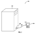
- FIG. 1 is a system diagram illustrating an operating environment in which example embodiments of the present disclosure can be applied;
- FIG. 2 is a perspective view of an electrical connector in accordance with example embodiments of the present disclosure
- FIG. 3 is a partial top view of the electrical connector of FIG. 2 in accordance with example embodiments of the present disclosure
- FIG. 4 is a cross sectional view of the electrical connector of FIGs. 2 and 3 taken along line 3-3 of FIG. 3 , in accordance with example embodiments of the present disclosure
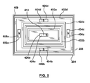
- FIG. 5 is a front view of the electrical connector of FIG. 2 in accordance with example embodiments of the present disclosure
- FIG. 6 is a front view of a complementary electrical connector for use with the electrical connector of FIGs. 2 to 5 in accordance with example embodiments of the present disclosure
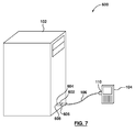
- FIG. 7 is a system diagram illustrating an operating environment in which example embodiments of the present disclosure can be applied.
- FIG. 8 is a perspective view of an electrical connection retrofit device in accordance with example embodiments of the present disclosure.
- FIG. 9 is a perspective view of an electrical connector in accordance with further example embodiments of the present disclosure.
- FIG. 10 is a front view of the electrical connector of FIG. 10 in accordance with example embodiments of the present disclosure.
- FIG. 11 is a front view of a complementary electrical connector for use with the electrical connector of FIG. 9 in accordance with example embodiments of the present disclosure.
- the present disclosure describes an electrical connector for connecting to a complementary electrical connector.
- the electrical connector comprises a main body containing one or more electrically conducting mediums.
- the electrical connector also comprises an end piece rotatably connected to the main body at one end of the main body.
- the end piece has a connecting side for engaging the complementary electrical connector.
- the end piece is rotatable about an axis of rotation.
- the connecting side comprises one or more electrical contacts for engaging complementary electrical contacts on the complementary electrical connector.
- Each electrical contact of the electrical connector is electrically connected to one of the electrically conducting mediums of the main body.
- the connecting side also comprises a magnet disposed on the connecting side of the end piece for engaging a complementary magnet on the complementary electrical connector.
- the magnet on the connecting side has at least one pole which is located at a position on the connecting side which is offset from the axis of rotation.
- the present disclosure describes an electronic device.
- the electrical device comprises an electrical connector for connecting to a complementary electrical connector.
- the electrical connector comprises a main body containing one or more electrically conducting mediums.
- the electrical connector also comprises an end piece rotatably connected to the main body at one end of the main body.
- the end piece has a connecting side for engaging the complementary electrical connector.
- the end piece is rotatable about an axis of rotation.
- the connecting side comprises one or more electrical contacts for engaging complementary electrical contacts on the complementary electrical connector.
- Each electrical contact of the electrical connector is electrically connected to one of the electrically conducting mediums of the main body.
- the connecting side also comprises a magnet disposed on the connecting side of the end piece for engaging a complementary magnet on the complementary electrical connector.
- the magnet on the connecting side has at least one pole which is located at a position on the connecting side which is offset from the axis of rotation.
- the present disclosure describes an electrical connection retrofit device.
- the electrical connection retrofit device comprises a magnetic electrical connecting end.
- the magnetic electrical connecting end comprises one or more electrical contacts for engaging corresponding electrical contacts on a magnetic electrical connector and a magnet for engaging a corresponding magnet on a magnetic electrical connector.
- the electrical connection retrofit device further comprises a non-magnetic electrical connecting end.
- the non magnetic electrical connecting end comprises one or more electrical contacts for engaging one or more corresponding electrical contacts on a complementary non-magnetic electrical connector.
- the electrical connection retrofit device further comprise an electrically conductive medium connecting the electrical contacts on the magnetic electrical connecting end to corresponding electrical contacts on the non-magnetic electrical connecting end.
- the present disclosure describes a first electrical connector for connecting to a complementary second electrical connector.
- the first electrical connector comprises a main body containing one or more electrically conducting mediums.
- the first electrical connector further comprises an end piece connected to the main body at one end of the main body.
- the end piece has a connecting side for engaging the second electrical connector.
- the connecting side includes a magnet disposed on the connecting side and two or more electric connectors comprised of two or more electrically conductive concentric circles, the electrically conductive circles being centered around the magnet.
- FIG. 1 shows an operating environment 100 in which example embodiments of the present disclosure can be applied.
- the operating environment 100 includes a first electronic device 102 and a second electronic device 104.
- the first electronic device 102 is a desktop computer and the second electronic device 104 is a smartphone.
- the first electronic device 102 and/or the second electronic device 104 may be of another type.
- the first electronic device 102 or the second electronic device 104 may be, for example, any of: a desktop computer, a notebook or laptop style computer, a tablet or slate computing device, a computer of another type, a global positioning system, a mobile communication device such as a smartphone, a personal digital assistant ("PDA"), a peripheral, such as a printer, scanner, headset, a hard drive, flash drive or other storage device.
- PDA personal digital assistant
- the first electronic device 102 and/or the second electronic device 104 may also be of another type not specifically listed above.
- An electrical connector 106 is used to connect the first electronic device 102 to the second electronic device 104.
- the electrical connector 106 provides a data connection between the first electronic device 102 and the second electronic device 104.
- the data connection is used to provide data communications between the first electronic device 102 and the second electronic device 104.
- the data connection permits the first electronic device 102 to send communications to and receive communications from the second electronic device 104 and permits the second electronic device 104 to send and receive communications from the first electronic device 102.
- the electrical connector 106 may be referred to as a data connector.
- the electrical connector 106 is received, at the first electronic device 102 by a first complementary electrical connector 108 which is provided by the first electronic device 102. That is, the electrical connector 106 engages the first complementary electrical connector 108 of the first electronic device 102.
- the first complementary electrical connector 108 is, in at least some embodiments, installed in the first electronic device 102 and communicatably connected to a processor (not shown) of the first electronic device 102; for example, through a communications bus.
- the electrical connector 106 may also be received, at the second electronic device 104 by a second complementary electrical connector 110 which is provided by the second electronic device 104. That is, the electrical connector 106 engages the second complementary electrical connector 110 of the second electronic device 104.
- the second complementary electrical connector is, in at least some embodiments, installed in the second electronic device 104 and communicatably connected to a processor (not shown) of the second electronic device 104; for example, through a communications bus.
- the electrical connector 106 may be used for providing electrical power from the first electronic device 102 to the second electronic device 104.
- the first complementary electrical connector 108 of the first electronic device 102 may be electrically connected to a power source (not shown) associated with the first electronic device 102.
- the second complementary electrical connector 110 of the second electronic device 104 may be electrically connected to power features (not shown) of the second electronic device 104.
- the power features may, for example, include a battery interface which uses electrical power supplied by the first electronic device 102 to charge a battery associated with the second electronic device 104.
- the power features may, in some embodiments, include circuitry which allows the second electronic device 104 to use the first electronic device 102 as a power source when the second electronic device 104 is connected to the first electronic device 102 via the electrical connector 106.
- FIG. 2 illustrates a perspective view of an electrical connector 106.
- FIG. 3 illustrates a partial top view of the electrical connector 106 of FIG. 2 .
- FIG. 4 illustrates a cross-sectional view of the electrical connector 106 of FIGs. 2 and 3 taken along line 3-3 of FIG. 3 .
- FIG. 4 illustrates a front view of the electrical connector 106 of FIG. 2 .
- the electrical connector 106 includes a main body 202 which contains one or more electrically conductive mediums 204.
- the main body 202 is an electrical cable and the electrically conductive mediums 204 include one or more wires. While a single electrically conductive medium 204 is illustrated in FIG. 2 , in practice, the cable will typically contain multiple electrically conductive mediums. For example, the cable may contain two or more wires.
- the electrical connector 106 includes an end piece 206.
- the end piece 206 is rotatably connected to the main body 202 at one end of the main body 202. That is, the end piece 206 is connected to the main body 202 so that it freely rotates about an axis of rotation 210.
- the axis of rotation 210 is, in at least some embodiments, located at a midpoint of the main body 202 where the main body 202 connects to the end piece 206. That is, in at least some example embodiments, the end piece 206 rotates about the midpoint of the main body 202.
- the end piece is provided with a rotating connector 232.
- the rotating connector 232 connects the end piece 206 to the main body 202 to permit the end piece 206 to rotate about the main body 202.
- Various types of rotating connectors 232 may be used.
- the rotating connector 232 is a modified bearing, which includes grippers on an interior side for gripping the main body 202 and which is connected to the end piece 206 on an exterior side of the rotating connector 232.
- the rotating connector 232 is also illustrated in the top view of FIG. 3 and is best illustrated in the cross-sectional view of FIG. 4 .
- the end piece 206 includes one or more electrical contacts 402a, 402b, 402c, 402d ( FIG. 5 ) disposed on a first connecting side 208 of the end piece 206.
- the electrical contacts of the end piece 206 are electrically connected to respective electrically conductive mediums 204 (i.e. wires) of the main body 202.
- the end piece 206 includes an electrically conductive mediums 236 which electrically connect to the electrically conductive mediums 204 of the main body 202 and also to the electrical contacts 402a, 402b, 402c, 402d ( FIG. 5 ) of the end piece 206.
- the electrically conductive medium 236 connects to a first electrical contact 402a.
- the end piece may contain more than one electrically conductive medium 236.
- the number of electrically conductive mediums 236 in the end piece 206 typically corresponds to the number of electrically conductive mediums 204 in the main body 202 and also the number of electrical contacts 402a, 402b, 402c, 402d on the end piece 206.
- the electrically conductive mediums 204 (i.e. wires) of the main body are rigidly connected to the end piece (i.e. if the wires of the cable are rigidly connected to the electrically conductive medium 236 of the end piece 206), then the rotation of the end piece 206 may be impeded.
- the electrically conductive mediums 204 of the main body are not rigidly connected to respective electrically conductive mediums 236 of the end piece 206.
- the end piece 206 may include an interior cavity which contains an electrical contact which wraps around the cavity.
- the end piece 206 contains a cylindrical interior 230 which contains one or more circular electrical contacts 234.
- the end piece 206 may contain a separate circular electrical contact 234 for each separate electrically conducting medium 204 in the main body.
- the circular electrical contact 234 wraps around the cylindrical interior 230, thus defining a circle. That is, the circular electrical contact 234 is a ring-like contact.
- Each circular electrical contact 234 is rigidly connected to a corresponding electrically conductive medium 236 in the end piece 206.
- Each circular electrical contact 234 is not rigidly connected to a corresponding electrically conductive medium 204 in the main body 202. Instead, a portion of the electrically conductive medium 204 in the main body 202 which protrudes from the main body is biased against a respective circular electrical contact 234.
- the electrically conductive medium 204 may, in some embodiments, be self-biased against its respective circular electrical contact 234.
- the electrically conductive medium 204 may be a rigid wire which is bent against the circular electrical contact 234.
- the electrically conductive medium may be held against the circular electrical contact 234 with a biasing feature (not shown).
- the end piece is permitted to move relative to the electrically conductive medium 204 in the main body, but an electrical connection is maintained between the circular electrical contact 234 and the electrically conductive medium 204 of the main body since the electrically conductive medium 204 of the main body is held against a point on the circle irrespective of the state of rotation of the end piece 206.
- the biasing feature may be provided in a variety of forms.
- the biasing feature may, in some embodiments, be provided by a leaf spring which biases the electrically conductive medium 204 of the main body 202 against the circular electrical contact 234.
- the electrical connector 106 may include a second end piece 220.
- the end piece 206 which was discussed above may also be referred to as a first end piece 206.
- the second end piece 220 may be connected to the main body at an end of the main body which is opposite to the end where the first end piece 206 was connected.
- the second end piece 220 includes a second connecting side 222.
- the second connecting side 222 is configured to connect to the second complementary electrical connector 110 ( FIG. 1 ) of the second electronic device 104 ( FIG. 1 ).
- the second end piece 220 is a non-magnetic connector.
- the second end piece 220 includes an electrically conductive medium 238 which connects the electrically conductive medium 204 of the main body 202 to electrical contacts 240 of the second end piece 220.
- the electrically conductive medium 238 of the second end piece 220 is illustrated using a separate reference numeral from the electrically conductive medium 204 of the main body 202, in practice, the electrically conductive medium 238 of the second end piece 220 and the electrically conductive medium 204 of the main body 202 may be a common element, such as a wire which runs through the main body 202 and which connects directly to the electrical contacts 240 of the second end piece 220.
- the electrical contacts 240 extend from a protruding section 242 of the second connecting side 222.
- the protruding section 242 is a male connector which may be received in a corresponding female electrical connector (i.e. the second complementary electrical connector 110 of FIG. 1 ) of the second electronic device 104 ( FIG. 1 ).
- the protruding section 242 friction fits within the second complementary electrical connector 110 ( FIG. 1 ) of the second electronic device 104 ( FIG. 1 ).
- the second end piece 220 is a micro-USB connector.
- FIG. 2 illustrates an embodiment in which the electrical connector 106 includes one magnetic type end piece (i.e. end piece 206) and one non-magnetic type end piece (i.e. second end piece 220), in other embodiments, the electrical connector 106 may include two magnetic type end pieces. That is, the second end piece 220 may, in some embodiments be of the type described in this document with reference to the first end piece 206 and the second complementary electrical connector 110 of the second electronic device 104 may be of the type described herein with reference to the first complementary electrical connector 108 of the first electronic device 102.
- FIG. 5 a front view of the electrical connector 106 of FIGs. 2 to 4 is illustrated. More particularly, the front view illustrates a connecting side 208 of the electrical connector 106.
- the connecting side 208 includes one or more electrical contacts 402a, 402b, 402c, 402d. In the embodiment illustrated, there are four electrical contacts - a first electrical contact 402a, a second electrical contact 402b, a third electrical contact 402c, and a fourth electrical contact 402d.
- Each electrical contact 402a, 402b, 402c, 402d of the electrical connector 106 may be comprised of one or more lines forming a polygon or circle. In the embodiment illustrated, the polygon is a rectangle comprised of four lines.
- each of the polygons or circles is different.
- the second electrical contact 402b is larger than the first electrical contact 402a
- the third electrical contact 402c is larger than the second electrical contact 402b
- the fourth electrical contact 402d is larger that the third electrical contact 402c.
- Each of the electrical contacts 402a, 402b, 402c, 402d is of the same geometric shape.
- each electrical contact is a rectangle.
- Each electrical contact 402a, 402b, 402c, 402d has a center point which is located at the axis of rotation 210 of the end piece 206.
- the electrical contacts 402a, 402b, 402c, 402d may be formed from shapes or objects which have a rotational symmetry about the axis of rotation 210 of an order greater than one.
- a shape with rotational symmetry is one that appears the same after a certain degree of rotation.
- the rectangular electrical contacts 402a, 402b, 402c, 402d have a second order rotational symmetry about the axis of rotation 210. That is, the electrical contacts 402a, 402b, 402c, 402d appear the same in two different rotational positions. For example, where the end piece 206 is rotated one-hundred and eighty degrees from the position illustrated in FIG.
- the electrical contacts will appear the same as they do in FIG. 5 . Since the rectangular electrical contacts 402a, 402b, 402c, 402d appear the same in two separate rotational positions about the axis of rotation 210, they are of the second order.
- the electrical connector 106 may connect to the complementary electrical connector 108 in more than one rotational position.
- the connecting side 208 of the end piece 206 of the electrical connector 106 also includes at least one magnet 404a, 404b, 404c, 404d, 404e disposed on the connecting side 208 of the end piece 206.
- At least one of the magnets 404a, 404b, 404c, 404d or 404e includes a magnetic pole 404a, 404b, 404c, 404d, 404e which is located at a position on the connecting side which is offset from the axis of rotation 210.
- a first magnet 404a has a first pole 406a which is offset from the axis of rotation.
- a second magnet 404c has a second pole 406b which is offset from the axis of rotation
- a third magnet 404b has a third pole 406c which is offset from the axis of rotation
- a fourth magnet 404d has a fourth pole 406d which is offset from the axis of rotation.
- the magnets 404a, 404b, 404c, 404d which have a pole 404a, 404b, 404c, 404d which is offset from the axis of rotation 210 may be used to provide self-aligning capabilities to the electrical connector 106.
- the magnets 404a, 404b, 404c, 404d, 404e may also be used to fasten the electrical connector 106 to a complementary electrical connector 108.
- the magnets 404a, 404b, 404c, 404d, 404e are used to fasten the electrical connector 106 to the first complementary electrical connector 108
- the magnets may include a magnet 404e which has a pole 406e which is not offset from the axis of rotation.
- a fifth magnet 404e includes a fifth pole 406e which may be located at the axis of rotation. The fifth pole 406e may be used to fasten the electrical connector 106 to the first complementary electrical connector 108.
- the electrical connector 106 includes five magnets.
- Four of the magnets 404a, 404b, 404c, 404d are located at a position which is offset from the axis of rotation 210.
- the fifth magnet 404e is located at the center of the axis of rotation 210.
- a first magnet 404a and a second magnet 404c are located near the shorter sides of the rectangular electrical contacts 402a, 402b, 402c, 402d.
- a third magnet 404b and a fourth magnet 404d are located near the longer sides of the rectangular electrical contacts 402a, 402b, 402c, 402d.
- the first magnet 404a and the second magnet 404c have exposed poles 406a, 406c which are of a first polarity (in the embodiment illustrated, they are magnetic north), and the third magnet 404b and the fourth magnet 404d have exposed poles 406b, 406d which are of a second polarity, which is opposite the first polarity (in the embodiment illustrated, they are magnetic south).
- the connecting side 208 may include a single magnet with a pole offset from the axis of rotation 210.
- the connecting side 208 may include two magnets with poles offset from the axis of rotation 210.
- the two magnets may each have a single exposed pole - a first magnet may include a first exposed pole and a second magnet may contain a second exposed pole.
- the first exposed pole may have a polarity which is opposite the polarity of the second exposed pole.
- exposed pole has been used to refer to a pole in which the magnetic field of that pole is exposed to elements which are external to the connector housing the magnet containing that pole.
- the connecting side 208 of the electrical connector 106 may include one or more aligning features 408.
- the aligning features prevent the electrical connector from contacting the first complementary electrical connector 108 in such a way that electrical contacts 402a, 402b, 402c, 402d on the electrical connector 106 may contact an electrical contact 502a, 502b, 502c, 502d ( FIG. 6 ) on the first complementary electrical connector which does not correspond to that electrical contact 402a, 402b, 402c, 402d on the electrical connector 106.
- the aligning feature 408 may, for example, be a rectangular protrusion or recess with a center point which is the same as the center point of the rectangles which form the electrical contacts 402a, 402b, 402c, 402d. As will be explained below with reference to FIG. 6 , the aligning feature 408 of the electrical connector 106 interacts with a corresponding aligning feature 508 of the complementary electrical connector 108.
- the connecting side 208 of the electrical connector 106 engages a complementary connecting side 510 of the complementary electrical connector 108.
- the complementary connecting side 510 of the complementary electrical connector 108 is a part of the complementary electrical connector 108 of the first electronic device 102 which may be exposed by the first electronic device 102.
- a front view of a complementary electrical connector 108 is illustrated in FIG. 6 .
- the complementary connecting side 510 of the complementary electrical connector 108 includes features which align with the features of the connecting side 208 of the electrical connector 106.
- the complementary connecting side 510 includes complementary electrical contacts 502a, 502b, 502c, 502d which engage the electrical contacts 402a, 402b, 402c, 402d of the connecting side 208 of the electrical connector 106. That is, when the electrical connector 106 of FIGs. 2 to 5 is connected to the complementary electrical connector 108 of FIG. 6 , the electrical contacts 402a, 402b, 402c, 402d of the electrical connector 106 contact respective electrical contacts 502a, 502b, 502c, 502d of the complementary electrical connector 108 thus providing electrical communication between the contacts. That is, the first electrical contact 402a engages a first complementary electrical contact 502a. Similarly, the second electrical contact 402b engages a second complementary electrical contact 502b, the third electrical contact 402c engages a third complementary electrical contact 502c, and the fourth electrical contact 402d engages a fourth complementary electrical contact 502d.
- the complementary electrical contacts 502a, 502b, 502c, 502d of the complementary electrical connector 108 are of a size and shape which correspond to the size and shape of the respective electrical contacts 402a, 402b, 402c, 402d.
- each complementary electrical contact 502a, 502b, 502c, 502d of the complementary electrical connector 108 may be comprised of one or more lines forming a polygon or circle. In the embodiment illustrated, the polygon is a rectangle comprised of four lines.
- each of the polygons or circles is different for each complementary electrical contact 502a, 502b, 502c, 502d.
- the second complementary electrical contact 502b is larger than the first complementary electrical contact 502a
- the third complementary electrical contact 502c is larger than the second complementary electrical contact 502b
- the fourth complementary electrical contact 502d is larger that the third complementary electrical contact 502c.
- each of the complementary electrical contacts 502a, 502b, 502c, 502d is of the same geometric shape.
- each complementary electrical contact is a rectangle.
- the complementary electrical connector 108 also includes one or more complementary magnets 504a, 504b, 504c, 504d, 504e disposed on the complementary connecting side 510.
- the complementary magnets 504a, 504b, 504c, 504d, 504e have complementary poles 506a, 506b, 506c, 506d, 506e respectively.
- the complementary magnets 504a, 504b, 504c, 504d, 504e are disposed on the complementary connecting side 510 so that, when the electrical connector 106 is connected to the complementary electrical connector 108, the complementary magnets 504a, 504b, 504c, 504d, 504e each engage a corresponding magnet 404a, 404b, 404c, 404d, 404e on the electrical connector 106.
- the complementary poles 506a, 506b, 506c, 506d, 506e of the complementary electrical connector 108 each engage a corresponding pole 406a, 406b, 406c, 406d, 406e (which is of the opposite polarity as the complementary pole 506a, 506b, 506c, 506d) on the complementary electrical connector 108.
- Each pole on the electrical connector 106 engages a corresponding pole on the complementary electrical connector 108 which is located at the same relative position, but which has an opposite polarity.
- an external magnetic field (which is produced by the magnets on the complementary electrical connector 108 on the first electronic device 102) may be applied to the poles 406a, 406b, 406c, 406d to cause the end piece 206 to rotate about the axis of rotation 210.
- the magnets may be used to self-align the electrical connector 106 with the first complementary electrical connector 108.
- the magnets 404a, 404b, 404c, 404d, 404e and corresponding complementary magnets 504a, 504b, 504c, 504d, 504e may also be used to connect the electrical connector 106 to the first complementary electrical connector 108. That is, a magnetic attraction force produced as a result of the magnetic fields of the magnets 404a, 404b, 404c, 404d, 404e and complementary magnets 504a, 504b, 504c, 504d, 504e on the first complementary electrical connector 108 may be used to fasten the electrical connector 106 to the first complementary electrical connector 108.
- the connecting side 208 of the end piece 206 may be flat, or substantially flat across its surface.
- the aligning feature 908 may, for example, be a circular protrusion or recess with a center point which is the same as the center point of the concentric circles which form the electrical contacts 902a, 902b, 902c, 902d.
- the aligning feature 908 of the electrical connector 106 interacts with a corresponding aligning feature 1008 of the complementary electrical connector 108.
- the connecting side 208 of the electrical connector 106 is flat across its surface, with the exception of the portion of the surface which includes an aligning feature 408.
- the portion of the surface which includes an aligning feature 408 may be raised or lowered relative to the other portions of the surface.
- the end piece may not include a protruding male connector or a recessed female connector.
- the complementary connecting side 510 of the complementary electrical connector may also be flat or substantially flat across its surface. The use of flat connecting sides may reduce the buildup of dust and other debris.
- a magnetic connection instead of a friction fit connection may protect electrical equipment, such as the electrical connector 106 from damage.
- a force When traditional connectors are connected, a force must be applied in a single direction in order to remove a male connector from a female connector. That is, the force must be applied directly away from the female connector. When a force is applied in another direction (for example, if a user accidentally impacts the connector) the connector may be damaged.
- the electrical connector 106 may be removed from a complementary electrical connector 108, even if the force is not applied directly away from the complementary connector.
- the complementary electrical connector 108 may also include one or more aligning features 508 which correspond to the aligning features 408 of the electrical connector 106.
- the aligning features prevent each of the electrical contacts 502a, 502b, 502c, 502d on the complementary electrical connector 108 from contacting a non-corresponding electrical contact 402a, 402b, 402c, 402d on the electrical connector 106. That is, the aligning features fervent the electrical connector 106 from contacting the first complementary electrical connector 108 in such a way that an electrical contact 402a, 402b, 402c, 402d on the electrical connector 106 may contact an electrical contact 502a, 502b, 502c, 502d ( FIG.
- the aligning feature 508 may, for example, be a rectangular protrusion or recess with a center point which is the same as the center point of the rectangles which form the electrical contacts 402a, 402b, 402c, 402d.
- the aligning feature 408 of the electrical connector 106 interacts with a corresponding aligning feature 508 of the complementary electrical connector 108.Other aligning features are also possible.
- the aligning features 408, 508 may allow the first electrical contact 402a on the electrical connector 106 to contact the first complementary electrical contact 502a on the complementary electrical connector 108, while preventing it from contacting the second complementary electrical contact 502b, the third complementary electrical contact 502c, and/or the fourth complementary electrical contact 502d.
- the aligning features 408, 508 may allow the second electrical contact 402b on the electrical connector 106 to contact the second complementary electrical contact 502b on the complementary electrical connector, while preventing it from contacting the first complementary electrical contact 502a, the third complementary electrical contact 502c and/or the fourth complementary electrical contact 502d.
- the aligning features 408, 508 may allow the third electrical contact 402c on the electrical connector 106 to contact the third complementary electrical contact 502c on the complementary electrical connector, while preventing it from contacting the first complementary electrical contact 502a, the second complementary electrical contact 502b and/or the fourth complementary electrical contact 502d.
- the aligning features 408, 508 may allow the fourth electrical contact 402d on the electrical connector 106 to contact the fourth complementary electrical contact 502d on the complementary electrical connector, while preventing it from contacting the first complementary electrical contact 502a, the second complementary electrical contact 502b and/or the third complementary electrical contact 502c.
- the aligning features 408 may not be included on the electrical connector 106 and complementary electrical connector 108. Instead, in at least some embodiments, alignment may be provided by the magnetic features of the connectors 106, 108 alone.
- the connecting side 208 and the complementary connecting side 510 are rectangular and have a rectangular perimeter or substantially rectangular perimeter. In at least some embodiments, the connecting side 208 and complementary connecting side 510 are of a size which corresponds to the size of a type A universal serial bus connector.
- an electrical connection retrofit device may be used to convert a non-magnetic electrical connector into a magnetic electrical connector which is capable of receiving a magnetic electrical connector 106 of the type described herein.
- FIG. 7 illustrates an operating environment 600 according to example embodiments of the present disclosure.
- the operating environment 600 includes a first electronic device 102 and a second electronic device 104.
- the first electronic device 102 does not include a magnetic electrical connector of a type which is capable of connecting directly to a magnetic electrical connector 106.
- the first electronic device 102 includes a non-magnetic port 608.
- the non-magnetic port may, for example, be a USB port.
- An electrical connection retrofit device 602 is used to allow the first electronic device 102 to connect to the electrical connector 106.
- the electrical connection retrofit device 602 includes a non-magnetic electrical connecting end 604 which is configured to be inserted into the non-magnetic port 608 and a magnetic electrical connecting end 606 which is configured to connect to the magnetic electrical connector 106 at the connecting side 208.
- the electrical connection retrofit device 602 includes the non-magnetic electrical connecting end 604 and the magnetic electrical connecting end 606.
- the non-magnetic electrical connecting end 604 is, in the embodiment illustrated, a USB connector which is configured for insertion into a USB port.
- the non-magnetic electrical connecting end 604 includes one or more electrical contacts 704a, 704b, 704c, 704d which are configured to contact corresponding electrical contacts in the non-magnetic port 608 ( FIG. 7 ) when the non-magnetic electrical connecting end 604 is inserted into the non-magnetic port 608 ( FIG. 7 ). That is, the electrical contacts 704a, 704b, 704c, 704d of the non-magnetic electrical connecting end 604 are configured for engaging complementary electrical contacts on a complementary non-magnetic connector (such as the non-magnetic port 608).
- a complementary non-magnetic connector such as the non-magnetic port 608
- the magnetic electrical connecting end 606 acts as the first complementary electrical connector 108 described above and includes features described above with reference to the complementary electrical connector 108 of FIG. 6 . More particularly, the magnetic electrical connecting end 606 includes one or more contacts 502a, 502b, 502c, 502d ( FIG. 6 ) for engaging corresponding electrical contacts 402a, 402b, 402c, 402d ( FIG. 5 ) on the magnetic electrical connector 106. The layout of the complementary electrical contacts 502a, 502b, 502c, 502d is described in greater detail above with reference to FIG. 6 .
- the electrical connection retrofit device 602 also includes one or more electrically conductive mediums (not shown) which internally connect electrical contacts 704a, 704b, 704c, 704d on the non-magnetic electrical connecting end 604 to corresponding electrical contacts 402a, 402b, 402c, 402d on the magnetic electrical connecting end 606.
- the magnetic electrical connecting end 606 also includes one or more magnets 504a, 504b, 504c, 504d, 504e ( FIG. 6 ) for engaging corresponding magnets 404a, 404b, 404c, 404d, 404e ( FIG. 5 ) on the magnetic electrical connector 106.
- the layout of the magnets 504a, 504b, 504c, 504d, 504e is described in greater detail above with reference to FIG. 6 .
- the electrical connection retrofit device 602 is sized so that it does not interfere with adjacent USB ports. Accordingly, in at least some embodiments, the electrical connection retrofit device 602 has a rectangular cross section which is of a size of typical USB connectors.
- the complementary electrical connector 108 may include a complementary connecting side 510 which rotates about a main body.
- the electrical connector 106 may not have a rotating end piece 206.
- an electrical connector 106 in accordance with further embodiments of the present application is illustrated.
- the electrical connector 106 may be used in operating environments of the type described above with reference to FIGs. 1 and/or 7.
- the electrical connector 106 includes a first end piece 206 which is connected to one end of a main body 202. Another end of the main body 202 is connected to a second end piece 220.
- the second end piece 220 may, in some embodiments (such as the embodiment illustrated), be a non-magnetic connector of the type described above with reference to FIG. 2 . In other embodiments, the second end piece 220 may be a magnetic connector of the type described throughout this document.
- the end piece 206 may be non-rotatable relative to the main body 202. That is, the end piece 206 may be rigidly connected to the main body 202.
- alignment of the electrical connector 106 with a complementary electrical connector may be provided through the use of electrical contacts which are in the form of concentric rings, and a magnet which is located at the centre of the concentric rings.
- FIG. 10 a front view of the electrical connector 106 of FIG. 9 is illustrated. More particularly, a front view of a connecting side 208 of the electrical connector is illustrated.
- the connecting side 208 of the electrical connector 106 includes one or more electrical contacts 902a, 902b, 902c, 902d.
- the electrical contacts 902a, 902b, 902c, 902d are concentric circles. That is, the electrical contacts 902a, 902b, 902c, 902d are concentric circular lines. Each circle has a different size, but has the same center point.
- the connecting side 208 of the electrical connector 106 also includes a circular magnet 904.
- the circular magnet 904 has a center point which is the center point of the concentric circles which form the electrical contacts 902a, 902b, 902c, 902d.
- the connecting side 208 includes one or more aligning features 908.
- the aligning features prevent the electrical connector 106 from contacting the first complementary electrical connector 108 in such a way that the electrical contacts 902a, 902b, 902c, 902d on the electrical connector 106 may contact a complementary electrical contact 1002a, 1002b, 1002c, 1002d ( FIG. 11 ) on the first complementary electrical connector which does not correspond to that electrical contact 902a, 902b, 902c, 902d on the electrical connector 106.
- the aligning feature 908 may, for example, be a circular protrusion or recess with a center point which is the same as the center point of the concentric circles which form the electrical contacts 902a, 902b, 902c, 902d. As will be explained below with reference to FIG. 11 , the aligning feature 908 of the electrical connector 106 interacts with a corresponding aligning feature 1008 of the complementary electrical connector 108.
- the connecting side 208 is, in at least some example embodiments, flat or substantially flat across its surface.
- FIG. 11 a front view of a complementary connecting side 510 of a complementary electrical connector 108 for use with the electrical connector 106 of FIG. 10 is illustrated.
- the connecting side 208 of the electrical connector 106 of FIG. 10 engages the complementary connecting side 510 of the complementary electrical connector 108 illustrated in FIG. 11 .
- the complementary connecting side 510 of the complementary electrical connector 108 includes features which align with the features of the connecting side 208 of the electrical connector 106.
- the complementary connecting side 510 includes complementary electrical contacts 1002a, 1002b, 1002c, 1002d which engage the electrical contacts 902a, 902b, 902c, 902d of the connecting side 208 of the electrical connector 106. That is, when the electrical connector 106 of FIG. 10 is connected to the complementary electrical connector 108 of FIG. 11 , the electrical contacts 902a, 902b, 902c, 902d of the electrical connector 106 contact respective complementary electrical contacts 1002a, 1002b, 1002c, 1002d of the complementary electrical connector 108 thus providing electrical communication between the contacts. That is, the first electrical contact 902a engages the first complementary electrical contact 1002a. Similarly, the second electrical contact 902b engages the second complementary electrical contact 1002b, the third electrical contact 902c engages the third complementary electrical contact 1002c, and the fourth electrical contact 902d engages the fourth complementary electrical contact 1002d.
- the complementary electrical contacts 1002a, 1002b, 1002c, 1002d of the complementary electrical connector 108 are of a size and shape which corresponds to the size and shape of the respective electrical contacts 902a, 902b, 902c, 902d. More particularly, the complementary electrical contacts 1002a, 1002b, 1002c, 1002d are formed of concentric circles. The size of each of the circles for each of the complementary electrical contacts 1002a, 1002b, 1002c, 1002d is different, but the circles share a common center point.
- the complementary connecting side 510 of the complementary electrical connector 108 also includes a circular complementary magnet 1004.
- the circular complementary magnet 1004 has a center point which is the center point of the concentric circles which form the complementary electrical contacts 1002a, 1002b, 1002c, 1002d.
- the polarity of the pole of the complementary magnet 1004 which is exposed on the complementary connecting side 510 of the complementary electrical connector 108 is opposite to the polarity of the pole of the magnet 904 which is exposed on the connecting side 208 of the electrical connector 106.
- the complementary magnet 1004 and the magnet 904 experience a magnetic attractive force which causes the electrical connector 106 to be held against the complementary electrical connector 108.
- the magnets 904, 1004 serve to hold electrical connector 106 in a position in which the electrical contacts 902a, 902b, 902c, 902d on the electrical connector 106 each contact a respective complementary electrical contact 1002a, 1002b, 1002c, 1002d on the complementary electrical connector 108 to provide electronic communication between the respective electrical contacts.
- the complementary connecting side 510 of the complementary electrical connector 108 includes one or more aligning features 1008 which interact with corresponding aligning features 908 of the electrical connector 106.
- the aligning features 908, 1008 prevent the electrical connector from contacting the first complementary electrical connector 108 in such a way that electrical contacts 902a, 902b, 902c, 902d on the electrical connector 106 may contact a complementary electrical contact 1002a, 1002b, 1002c, 1002d ( FIG. 11 ) on the first complementary electrical connector which does not correspond to that electrical contact 902a, 902b, 902c, 902d on the electrical connector 106.
- the aligning feature 1008 may, for example, be a circular protrusion or recess with a center point which is the same as the center point of the concentric circles which form the complementary electrical contacts 1002a, 1002b, 1002c, 1002d.
- the circular protrusion or recess may be received or may receive the aligning feature 908 of the electrical connector 106 only when the electrical connector 106 is properly aligned with the complementary electrical connector 108.
- the complementary connecting side 510 of the complementary electrical connector 108 is flat or substantially flat across its surface.
- the magnets 404a, 404b, 404c, 404d, 404e ( FIG. 5 ), 504a, 504b, 504c, 504d, 504e ( FIG. 5 ), 904 ( FIG. 10 ) and 1004 ( FIG. 11 ) described above may, in some embodiments, be permanent magnets such as, for example, rare earth magnets.
- one or more of the magnets 404a, 404b, 404c, 404d, 404e ( FIG. 5 ), 504a, 504b, 504c, 504d, 504e ( FIG.6 ), 904 ( FIG. 10 ) and 1004 ( FIG. 11 ) described above may be electro-magnets.
- main body 202 of the electrical connectors described above has, generally, been illustrated as a cable which connects a first end piece 206 to a second end piece 220, in other embodiments, the main body may take other forms.
- the main body is an electronic device, such as, for example, a flash memory device.
- an apparatus for establishing an electrical connection includes a first connector, which may be the electrical connector 106.
- the apparatus also includes a second connector, which may be the complementary electrical connector 108 described above.
- an electronic device which includes an electrical connector.
- the electrical connector of the electronic device may, for example, be the electrical connector 106 described above or the complementary electrical connector 108 described above.
Landscapes
- Details Of Connecting Devices For Male And Female Coupling (AREA)
Abstract
Description
- The present disclosure relates to electrical connectors and more particularly to a self orienting electrical connector.
- Electrical connectors, such as data cables, are frequently used to establish a data connection between electronic devices. For example, Universal Serial Bus ("USB") connectors are frequently connected to electronic devices, such as, for example, computers or computer peripherals.
- USB connectors and other data connectors typically include a female connector installed on an electronic device which receives a corresponding male connector which may be installed, for example, on a data cable.
- Since the male connector is physically inserted into the female connector, the connectors may become damaged if the male connector is accidentally impacted. Furthermore, in order to physically insert the male connector into the female connector, the connectors must be properly aligned. Aligning the connectors is sometimes difficult where one of the connectors is obscured. For example, USB connectors are often provided on a back-side of desktop computers. In such cases, users are sometimes faced with the difficult task of inserting a USB data cable into a complementary connector which is not visible.
- Thus, there exists a need for improved electronic connectors.
-
FIG. 1 is a system diagram illustrating an operating environment in which example embodiments of the present disclosure can be applied; -
FIG. 2 is a perspective view of an electrical connector in accordance with example embodiments of the present disclosure; -
FIG. 3 is a partial top view of the electrical connector ofFIG. 2 in accordance with example embodiments of the present disclosure; -
FIG. 4 is a cross sectional view of the electrical connector ofFIGs. 2 and3 taken along line 3-3 ofFIG. 3 , in accordance with example embodiments of the present disclosure; -
FIG. 5 is a front view of the electrical connector ofFIG. 2 in accordance with example embodiments of the present disclosure; -
FIG. 6 is a front view of a complementary electrical connector for use with the electrical connector ofFIGs. 2 to 5 in accordance with example embodiments of the present disclosure; -
FIG. 7 is a system diagram illustrating an operating environment in which example embodiments of the present disclosure can be applied; -
FIG. 8 is a perspective view of an electrical connection retrofit device in accordance with example embodiments of the present disclosure; -
FIG. 9 is a perspective view of an electrical connector in accordance with further example embodiments of the present disclosure; -
FIG. 10 is a front view of the electrical connector ofFIG. 10 in accordance with example embodiments of the present disclosure; and -
FIG. 11 is a front view of a complementary electrical connector for use with the electrical connector ofFIG. 9 in accordance with example embodiments of the present disclosure. - It will be noted that throughout the drawings and description similar features are identified by the same reference numerals.
- The present disclosure describes an electrical connector for connecting to a complementary electrical connector. The electrical connector comprises a main body containing one or more electrically conducting mediums. The electrical connector also comprises an end piece rotatably connected to the main body at one end of the main body. The end piece has a connecting side for engaging the complementary electrical connector. The end piece is rotatable about an axis of rotation. The connecting side comprises one or more electrical contacts for engaging complementary electrical contacts on the complementary electrical connector. Each electrical contact of the electrical connector is electrically connected to one of the electrically conducting mediums of the main body. The connecting side also comprises a magnet disposed on the connecting side of the end piece for engaging a complementary magnet on the complementary electrical connector. The magnet on the connecting side has at least one pole which is located at a position on the connecting side which is offset from the axis of rotation.
- In another aspect, the present disclosure describes an electronic device. The electrical device comprises an electrical connector for connecting to a complementary electrical connector. The electrical connector comprises a main body containing one or more electrically conducting mediums. The electrical connector also comprises an end piece rotatably connected to the main body at one end of the main body. The end piece has a connecting side for engaging the complementary electrical connector. The end piece is rotatable about an axis of rotation. The connecting side comprises one or more electrical contacts for engaging complementary electrical contacts on the complementary electrical connector. Each electrical contact of the electrical connector is electrically connected to one of the electrically conducting mediums of the main body. The connecting side also comprises a magnet disposed on the connecting side of the end piece for engaging a complementary magnet on the complementary electrical connector. The magnet on the connecting side has at least one pole which is located at a position on the connecting side which is offset from the axis of rotation.In yet a further aspect, the present disclosure describes an electrical connection retrofit device. The electrical connection retrofit device comprises a magnetic electrical connecting end. The magnetic electrical connecting end comprises one or more electrical contacts for engaging corresponding electrical contacts on a magnetic electrical connector and a magnet for engaging a corresponding magnet on a magnetic electrical connector. The electrical connection retrofit device further comprises a non-magnetic electrical connecting end. The non magnetic electrical connecting end comprises one or more electrical contacts for engaging one or more corresponding electrical contacts on a complementary non-magnetic electrical connector. The electrical connection retrofit device further comprise an electrically conductive medium connecting the electrical contacts on the magnetic electrical connecting end to corresponding electrical contacts on the non-magnetic electrical connecting end.
- In a further aspect, the present disclosure describes a first electrical connector for connecting to a complementary second electrical connector. The first electrical connector comprises a main body containing one or more electrically conducting mediums. The first electrical connector further comprises an end piece connected to the main body at one end of the main body. The end piece has a connecting side for engaging the second electrical connector. The connecting side includes a magnet disposed on the connecting side and two or more electric connectors comprised of two or more electrically conductive concentric circles, the electrically conductive circles being centered around the magnet.
- Other example embodiments of the present application will be apparent to those of ordinary skill in the art from a review of the following detailed description in conjunction with the drawings.
- In order to facilitate an understanding of one possible environment in which example embodiments described herein can operate, reference is first made to
FIG. 1 which shows anoperating environment 100 in which example embodiments of the present disclosure can be applied. Theoperating environment 100 includes a firstelectronic device 102 and a secondelectronic device 104. - In the example embodiment illustrated, the first
electronic device 102 is a desktop computer and the secondelectronic device 104 is a smartphone. In other example embodiments, the firstelectronic device 102 and/or the secondelectronic device 104 may be of another type. For example, in various embodiments, the firstelectronic device 102 or the secondelectronic device 104 may be, for example, any of: a desktop computer, a notebook or laptop style computer, a tablet or slate computing device, a computer of another type, a global positioning system, a mobile communication device such as a smartphone, a personal digital assistant ("PDA"), a peripheral, such as a printer, scanner, headset, a hard drive, flash drive or other storage device. The firstelectronic device 102 and/or the secondelectronic device 104 may also be of another type not specifically listed above. - An
electrical connector 106 is used to connect the firstelectronic device 102 to the secondelectronic device 104. Theelectrical connector 106 provides a data connection between the firstelectronic device 102 and the secondelectronic device 104. The data connection is used to provide data communications between the firstelectronic device 102 and the secondelectronic device 104. For example, the data connection permits the firstelectronic device 102 to send communications to and receive communications from the secondelectronic device 104 and permits the secondelectronic device 104 to send and receive communications from the firstelectronic device 102. Theelectrical connector 106 may be referred to as a data connector. - The
electrical connector 106 is received, at the firstelectronic device 102 by a first complementaryelectrical connector 108 which is provided by the firstelectronic device 102. That is, theelectrical connector 106 engages the first complementaryelectrical connector 108 of the firstelectronic device 102. The first complementaryelectrical connector 108 is, in at least some embodiments, installed in the firstelectronic device 102 and communicatably connected to a processor (not shown) of the firstelectronic device 102; for example, through a communications bus. - The
electrical connector 106 may also be received, at the secondelectronic device 104 by a second complementaryelectrical connector 110 which is provided by the secondelectronic device 104. That is, theelectrical connector 106 engages the second complementaryelectrical connector 110 of the secondelectronic device 104. The second complementary electrical connector is, in at least some embodiments, installed in the secondelectronic device 104 and communicatably connected to a processor (not shown) of the secondelectronic device 104; for example, through a communications bus. - In at least some example embodiments, the
electrical connector 106 may be used for providing electrical power from the firstelectronic device 102 to the secondelectronic device 104. In such embodiments, the first complementaryelectrical connector 108 of the firstelectronic device 102 may be electrically connected to a power source (not shown) associated with the firstelectronic device 102. Similarly, the second complementaryelectrical connector 110 of the secondelectronic device 104 may be electrically connected to power features (not shown) of the secondelectronic device 104. The power features may, for example, include a battery interface which uses electrical power supplied by the firstelectronic device 102 to charge a battery associated with the secondelectronic device 104. The power features may, in some embodiments, include circuitry which allows the secondelectronic device 104 to use the firstelectronic device 102 as a power source when the secondelectronic device 104 is connected to the firstelectronic device 102 via theelectrical connector 106. - An overview having been provided, reference will now be made to
FIGs. 2 to 4 which further illustrate anelectrical connector 106 in accordance with some example embodiments of the present disclosure.FIG. 2 illustrates a perspective view of anelectrical connector 106.FIG. 3 illustrates a partial top view of theelectrical connector 106 ofFIG. 2 .FIG. 4 illustrates a cross-sectional view of theelectrical connector 106 ofFIGs. 2 and3 taken along line 3-3 ofFIG. 3 .FIG. 4 illustrates a front view of theelectrical connector 106 ofFIG. 2 . - Referring first to
FIG. 2 , theelectrical connector 106 includes amain body 202 which contains one or more electricallyconductive mediums 204. In the embodiment ofFIG. 2 , themain body 202 is an electrical cable and the electricallyconductive mediums 204 include one or more wires. While a single electricallyconductive medium 204 is illustrated inFIG. 2 , in practice, the cable will typically contain multiple electrically conductive mediums. For example, the cable may contain two or more wires. - The
electrical connector 106 includes anend piece 206. Theend piece 206 is rotatably connected to themain body 202 at one end of themain body 202. That is, theend piece 206 is connected to themain body 202 so that it freely rotates about an axis ofrotation 210. The axis ofrotation 210 is, in at least some embodiments, located at a midpoint of themain body 202 where themain body 202 connects to theend piece 206. That is, in at least some example embodiments, theend piece 206 rotates about the midpoint of themain body 202. - To permit the
end piece 206 to rotate, the end piece is provided with arotating connector 232. Therotating connector 232 connects theend piece 206 to themain body 202 to permit theend piece 206 to rotate about themain body 202. Various types ofrotating connectors 232 may be used. For example, in at least some embodiments, the rotatingconnector 232 is a modified bearing, which includes grippers on an interior side for gripping themain body 202 and which is connected to theend piece 206 on an exterior side of therotating connector 232. Therotating connector 232 is also illustrated in the top view ofFIG. 3 and is best illustrated in the cross-sectional view ofFIG. 4 . - As will be discussed in greater detail below with reference to
FIG. 5 , theend piece 206 includes one or moreelectrical contacts FIG. 5 ) disposed on a first connectingside 208 of theend piece 206. The electrical contacts of theend piece 206 are electrically connected to respective electrically conductive mediums 204 (i.e. wires) of themain body 202. For example, in the embodiment illustrated, theend piece 206 includes an electricallyconductive mediums 236 which electrically connect to the electricallyconductive mediums 204 of themain body 202 and also to theelectrical contacts FIG. 5 ) of theend piece 206. In the embodiment illustrated, the electricallyconductive medium 236 connects to a firstelectrical contact 402a. - While a single electrically
conductive medium 236 is illustrated within the end piece ofFIGs. 2 to 4 , in practice, the end piece may contain more than one electricallyconductive medium 236. The number of electricallyconductive mediums 236 in theend piece 206 typically corresponds to the number of electricallyconductive mediums 204 in themain body 202 and also the number ofelectrical contacts end piece 206. - It will be appreciated that, if the electrically conductive mediums 204 (i.e. wires) of the main body (i.e. cable) are rigidly connected to the end piece (i.e. if the wires of the cable are rigidly connected to the electrically
conductive medium 236 of the end piece 206), then the rotation of theend piece 206 may be impeded. Accordingly, in at least some embodiments, the electricallyconductive mediums 204 of the main body are not rigidly connected to respective electricallyconductive mediums 236 of theend piece 206. Instead, theend piece 206 may include an interior cavity which contains an electrical contact which wraps around the cavity. For example, in the embodiment illustrated, theend piece 206 contains acylindrical interior 230 which contains one or more circularelectrical contacts 234. Theend piece 206 may contain a separate circularelectrical contact 234 for each separate electrically conducting medium 204 in the main body. The circularelectrical contact 234 wraps around thecylindrical interior 230, thus defining a circle. That is, the circularelectrical contact 234 is a ring-like contact. - Each circular
electrical contact 234 is rigidly connected to a corresponding electrically conductive medium 236 in theend piece 206. Each circularelectrical contact 234 is not rigidly connected to a corresponding electrically conductive medium 204 in themain body 202. Instead, a portion of the electrically conductive medium 204 in themain body 202 which protrudes from the main body is biased against a respective circularelectrical contact 234. The electrically conductive medium 204 may, in some embodiments, be self-biased against its respective circularelectrical contact 234. For example, the electrically conductive medium 204 may be a rigid wire which is bent against the circularelectrical contact 234. In other example embodiments, the electrically conductive medium may be held against the circularelectrical contact 234 with a biasing feature (not shown). Thus, the end piece is permitted to move relative to the electrically conductive medium 204 in the main body, but an electrical connection is maintained between the circularelectrical contact 234 and the electricallyconductive medium 204 of the main body since the electricallyconductive medium 204 of the main body is held against a point on the circle irrespective of the state of rotation of theend piece 206. - The biasing feature (not shown) may be provided in a variety of forms. For example, the biasing feature (not shown) may, in some embodiments, be provided by a leaf spring which biases the electrically
conductive medium 204 of themain body 202 against the circularelectrical contact 234. - In at least some embodiments, the
electrical connector 106 may include asecond end piece 220. In such embodiments, theend piece 206 which was discussed above may also be referred to as afirst end piece 206. Thesecond end piece 220 may be connected to the main body at an end of the main body which is opposite to the end where thefirst end piece 206 was connected. - The
second end piece 220 includes a second connectingside 222. The second connectingside 222 is configured to connect to the second complementary electrical connector 110 (FIG. 1 ) of the second electronic device 104 (FIG. 1 ). In the embodiment shown inFIG. 2 , thesecond end piece 220 is a non-magnetic connector. Thesecond end piece 220 includes an electrically conductive medium 238 which connects the electricallyconductive medium 204 of themain body 202 toelectrical contacts 240 of thesecond end piece 220. While the electricallyconductive medium 238 of thesecond end piece 220 is illustrated using a separate reference numeral from the electricallyconductive medium 204 of themain body 202, in practice, the electricallyconductive medium 238 of thesecond end piece 220 and the electricallyconductive medium 204 of themain body 202 may be a common element, such as a wire which runs through themain body 202 and which connects directly to theelectrical contacts 240 of thesecond end piece 220. - The
electrical contacts 240 extend from a protrudingsection 242 of the second connectingside 222. The protrudingsection 242 is a male connector which may be received in a corresponding female electrical connector (i.e. the second complementaryelectrical connector 110 ofFIG. 1 ) of the second electronic device 104 (FIG. 1 ). The protrudingsection 242 friction fits within the second complementary electrical connector 110 (FIG. 1 ) of the second electronic device 104 (FIG. 1 ). In at least some embodiments, thesecond end piece 220 is a micro-USB connector. - While
FIG. 2 illustrates an embodiment in which theelectrical connector 106 includes one magnetic type end piece (i.e. end piece 206) and one non-magnetic type end piece (i.e. second end piece 220), in other embodiments, theelectrical connector 106 may include two magnetic type end pieces. That is, thesecond end piece 220 may, in some embodiments be of the type described in this document with reference to thefirst end piece 206 and the second complementaryelectrical connector 110 of the secondelectronic device 104 may be of the type described herein with reference to the first complementaryelectrical connector 108 of the firstelectronic device 102. - Referring now to
FIG. 5 , a front view of theelectrical connector 106 ofFIGs. 2 to 4 is illustrated. More particularly, the front view illustrates a connectingside 208 of theelectrical connector 106. The connectingside 208 includes one or moreelectrical contacts electrical contact 402a, a secondelectrical contact 402b, a thirdelectrical contact 402c, and a fourthelectrical contact 402d. Eachelectrical contact electrical connector 106 may be comprised of one or more lines forming a polygon or circle. In the embodiment illustrated, the polygon is a rectangle comprised of four lines. - The size of each of the polygons or circles is different. For example in the embodiment of
FIG. 5 , the secondelectrical contact 402b is larger than the firstelectrical contact 402a, the thirdelectrical contact 402c is larger than the secondelectrical contact 402b, and the fourthelectrical contact 402d is larger that the thirdelectrical contact 402c. - Each of the
electrical contacts FIG. 5 , each electrical contact is a rectangle. Eachelectrical contact rotation 210 of theend piece 206. - In some example embodiments, the
electrical contacts rotation 210 of an order greater than one. A shape with rotational symmetry is one that appears the same after a certain degree of rotation. In the embodiment illustrated inFIG. 5 , the rectangularelectrical contacts rotation 210. That is, theelectrical contacts end piece 206 is rotated one-hundred and eighty degrees from the position illustrated inFIG. 5 , the electrical contacts will appear the same as they do inFIG. 5 . Since the rectangularelectrical contacts rotation 210, they are of the second order. - By using
electrical contacts electrical connector 106 may connect to the complementaryelectrical connector 108 in more than one rotational position. - The connecting
side 208 of theend piece 206 of theelectrical connector 106 also includes at least onemagnet side 208 of theend piece 206. At least one of themagnets magnetic pole rotation 210. For example, in the embodiment illustrated, afirst magnet 404a has afirst pole 406a which is offset from the axis of rotation. Similarly, asecond magnet 404c has asecond pole 406b which is offset from the axis of rotation, athird magnet 404b has athird pole 406c which is offset from the axis of rotation and afourth magnet 404d has afourth pole 406d which is offset from the axis of rotation. - As will be explained in greater detail below with reference to
FIG. 6 , themagnets pole rotation 210 may be used to provide self-aligning capabilities to theelectrical connector 106. Themagnets electrical connector 106 to a complementaryelectrical connector 108. - Where the
magnets electrical connector 106 to the first complementaryelectrical connector 108, the magnets may include amagnet 404e which has apole 406e which is not offset from the axis of rotation. For example, in the example illustrated, afifth magnet 404e includes afifth pole 406e which may be located at the axis of rotation. Thefifth pole 406e may be used to fasten theelectrical connector 106 to the first complementaryelectrical connector 108. - In the embodiment of
FIG. 5 , theelectrical connector 106 includes five magnets. Four of themagnets rotation 210. Thefifth magnet 404e is located at the center of the axis ofrotation 210. In the embodiment illustrated, afirst magnet 404a and asecond magnet 404c are located near the shorter sides of the rectangularelectrical contacts third magnet 404b and afourth magnet 404d are located near the longer sides of the rectangularelectrical contacts first magnet 404a and thesecond magnet 404c have exposedpoles third magnet 404b and thefourth magnet 404d have exposedpoles - In other example embodiments, other magnet layouts may be used. For example, in one example embodiment (not illustrated), the connecting
side 208 may include a single magnet with a pole offset from the axis ofrotation 210. - In other example embodiments (not illustrated), the connecting
side 208 may include two magnets with poles offset from the axis ofrotation 210. The two magnets may each have a single exposed pole - a first magnet may include a first exposed pole and a second magnet may contain a second exposed pole. The first exposed pole may have a polarity which is opposite the polarity of the second exposed pole. The term exposed pole has been used to refer to a pole in which the magnetic field of that pole is exposed to elements which are external to the connector housing the magnet containing that pole. - In at least some embodiments, the connecting
side 208 of theelectrical connector 106 may include one or more aligning features 408. The aligning features prevent the electrical connector from contacting the first complementaryelectrical connector 108 in such a way thatelectrical contacts electrical connector 106 may contact anelectrical contact FIG. 6 ) on the first complementary electrical connector which does not correspond to thatelectrical contact electrical connector 106. - The aligning
feature 408 may, for example, be a rectangular protrusion or recess with a center point which is the same as the center point of the rectangles which form theelectrical contacts FIG. 6 , the aligningfeature 408 of theelectrical connector 106 interacts with a corresponding aligningfeature 508 of the complementaryelectrical connector 108. - The connecting
side 208 of theelectrical connector 106 engages a complementary connectingside 510 of the complementaryelectrical connector 108. The complementary connectingside 510 of the complementaryelectrical connector 108 is a part of the complementaryelectrical connector 108 of the firstelectronic device 102 which may be exposed by the firstelectronic device 102. A front view of a complementaryelectrical connector 108 is illustrated inFIG. 6 . - The complementary connecting
side 510 of the complementaryelectrical connector 108 includes features which align with the features of the connectingside 208 of theelectrical connector 106. - For example, the complementary connecting
side 510 includes complementaryelectrical contacts electrical contacts side 208 of theelectrical connector 106. That is, when theelectrical connector 106 ofFIGs. 2 to 5 is connected to the complementaryelectrical connector 108 ofFIG. 6 , theelectrical contacts electrical connector 106 contact respectiveelectrical contacts electrical connector 108 thus providing electrical communication between the contacts. That is, the firstelectrical contact 402a engages a first complementaryelectrical contact 502a. Similarly, the secondelectrical contact 402b engages a second complementaryelectrical contact 502b, the thirdelectrical contact 402c engages a third complementaryelectrical contact 502c, and the fourthelectrical contact 402d engages a fourth complementaryelectrical contact 502d. - Accordingly, in at least some embodiments, the complementary
electrical contacts electrical connector 108 are of a size and shape which correspond to the size and shape of the respectiveelectrical contacts electrical contact electrical connector 108 may be comprised of one or more lines forming a polygon or circle. In the embodiment illustrated, the polygon is a rectangle comprised of four lines. - The size of each of the polygons or circles is different for each complementary
electrical contact FIG. 6 , the second complementaryelectrical contact 502b is larger than the first complementaryelectrical contact 502a, the third complementaryelectrical contact 502c is larger than the second complementaryelectrical contact 502b, and the fourth complementaryelectrical contact 502d is larger that the third complementaryelectrical contact 502c. - Each of the complementary
electrical contacts FIG. 6 , each complementary electrical contact is a rectangle. - The complementary
electrical connector 108 also includes one or morecomplementary magnets side 510. Thecomplementary magnets complementary poles complementary magnets side 510 so that, when theelectrical connector 106 is connected to the complementaryelectrical connector 108, thecomplementary magnets corresponding magnet electrical connector 106. That is, when theelectrical connector 106 is connected to the complementaryelectrical connector 108, thecomplementary poles electrical connector 108 each engage acorresponding pole complementary pole electrical connector 108. Each pole on theelectrical connector 106 engages a corresponding pole on the complementaryelectrical connector 108 which is located at the same relative position, but which has an opposite polarity. - Since the
poles electrical connector 106 are offset from the axis ofrotation 210, an external magnetic field (which is produced by the magnets on the complementaryelectrical connector 108 on the first electronic device 102) may be applied to thepoles end piece 206 to rotate about the axis ofrotation 210. Thus, the magnets may be used to self-align theelectrical connector 106 with the first complementaryelectrical connector 108. - The
magnets complementary magnets electrical connector 106 to the first complementaryelectrical connector 108. That is, a magnetic attraction force produced as a result of the magnetic fields of themagnets complementary magnets electrical connector 108 may be used to fasten theelectrical connector 106 to the first complementaryelectrical connector 108. - By using magnets instead of a traditional friction fit electrical connector, the connecting
side 208 of theend piece 206 may be flat, or substantially flat across its surface. The aligningfeature 908 may, for example, be a circular protrusion or recess with a center point which is the same as the center point of the concentric circles which form theelectrical contacts FIG. 11 , the aligningfeature 908 of theelectrical connector 106 interacts with a corresponding aligningfeature 1008 of the complementaryelectrical connector 108. - In at least some embodiments, the connecting
side 208 of theelectrical connector 106 is flat across its surface, with the exception of the portion of the surface which includes an aligningfeature 408. The portion of the surface which includes an aligningfeature 408 may be raised or lowered relative to the other portions of the surface. - That is, the end piece may not include a protruding male connector or a recessed female connector. Similarly, the complementary connecting
side 510 of the complementary electrical connector may also be flat or substantially flat across its surface. The use of flat connecting sides may reduce the buildup of dust and other debris. - The use of a magnetic connection instead of a friction fit connection may protect electrical equipment, such as the
electrical connector 106 from damage. When traditional connectors are connected, a force must be applied in a single direction in order to remove a male connector from a female connector. That is, the force must be applied directly away from the female connector. When a force is applied in another direction (for example, if a user accidentally impacts the connector) the connector may be damaged. By using a magnetic connector, theelectrical connector 106 may be removed from a complementaryelectrical connector 108, even if the force is not applied directly away from the complementary connector. - The complementary
electrical connector 108 may also include one or more aligningfeatures 508 which correspond to the aligningfeatures 408 of theelectrical connector 106. The aligning features prevent each of theelectrical contacts electrical connector 108 from contacting a non-correspondingelectrical contact electrical connector 106. That is, the aligning features fervent theelectrical connector 106 from contacting the first complementaryelectrical connector 108 in such a way that anelectrical contact electrical connector 106 may contact anelectrical contact FIG. 6 ) on the first complementary electrical connector which does not correspond to thatelectrical contact electrical connector 106. The aligningfeature 508 may, for example, be a rectangular protrusion or recess with a center point which is the same as the center point of the rectangles which form theelectrical contacts feature 408 of theelectrical connector 106 interacts with a corresponding aligningfeature 508 of the complementary electrical connector 108.Other aligning features are also possible. - For example the aligning
features electrical contact 402a on theelectrical connector 106 to contact the first complementaryelectrical contact 502a on the complementaryelectrical connector 108, while preventing it from contacting the second complementaryelectrical contact 502b, the third complementaryelectrical contact 502c, and/or the fourth complementaryelectrical contact 502d. Similarly, the aligningfeatures electrical contact 402b on theelectrical connector 106 to contact the second complementaryelectrical contact 502b on the complementary electrical connector, while preventing it from contacting the first complementaryelectrical contact 502a, the third complementaryelectrical contact 502c and/or the fourth complementaryelectrical contact 502d. Similarly, the aligningfeatures electrical contact 402c on theelectrical connector 106 to contact the third complementaryelectrical contact 502c on the complementary electrical connector, while preventing it from contacting the first complementaryelectrical contact 502a, the second complementaryelectrical contact 502b and/or the fourth complementaryelectrical contact 502d. Similarly, the aligningfeatures electrical contact 402d on theelectrical connector 106 to contact the fourth complementaryelectrical contact 502d on the complementary electrical connector, while preventing it from contacting the first complementaryelectrical contact 502a, the second complementaryelectrical contact 502b and/or the third complementaryelectrical contact 502c. - In some embodiments (not shown), the aligning features 408 (
FIG. 5 ), 508 (FIG. 6 ) may not be included on theelectrical connector 106 and complementaryelectrical connector 108. Instead, in at least some embodiments, alignment may be provided by the magnetic features of theconnectors - In at least some embodiments, in order to provide a form factor which is similar to the form factor of standard Type A universal serial bus (USB) connectors, the connecting
side 208 and the complementary connectingside 510 are rectangular and have a rectangular perimeter or substantially rectangular perimeter. In at least some embodiments, the connectingside 208 and complementary connectingside 510 are of a size which corresponds to the size of a type A universal serial bus connector. - In some applications, it may be desirable to use the
electrical connector 106 described herein with a firstelectronic device 102 which may not have an integrated complementaryelectrical connector 108 of the type described above with reference toFIG. 6 . Such electronic devices may, however, have other electrical connectors included therein. For example, as discussed above, non-magnetic connectors, such as USB ports, are often included in computers. Accordingly, in at least some embodiments, an electrical connection retrofit device may be used to convert a non-magnetic electrical connector into a magnetic electrical connector which is capable of receiving a magneticelectrical connector 106 of the type described herein. - An overview having been provided, reference will now be made to
FIG. 7 which illustrates an operatingenvironment 600 according to example embodiments of the present disclosure. The operatingenvironment 600 includes a firstelectronic device 102 and a secondelectronic device 104. In the embodiment ofFIG. 7 , the firstelectronic device 102 does not include a magnetic electrical connector of a type which is capable of connecting directly to a magneticelectrical connector 106. Instead, the firstelectronic device 102 includes anon-magnetic port 608. The non-magnetic port may, for example, be a USB port. - An electrical
connection retrofit device 602 is used to allow the firstelectronic device 102 to connect to theelectrical connector 106. - The electrical
connection retrofit device 602 includes a non-magnetic electrical connectingend 604 which is configured to be inserted into thenon-magnetic port 608 and a magnetic electrical connectingend 606 which is configured to connect to the magneticelectrical connector 106 at the connectingside 208. - Referring now to
FIG. 8 , a perspective view of the electricalconnection retrofit device 602 ofFIG. 7 is illustrated. The electricalconnection retrofit device 602 includes the non-magnetic electrical connectingend 604 and the magnetic electrical connectingend 606. The non-magnetic electrical connectingend 604 is, in the embodiment illustrated, a USB connector which is configured for insertion into a USB port. The non-magnetic electrical connectingend 604 includes one or moreelectrical contacts FIG. 7 ) when the non-magnetic electrical connectingend 604 is inserted into the non-magnetic port 608 (FIG. 7 ). That is, theelectrical contacts end 604 are configured for engaging complementary electrical contacts on a complementary non-magnetic connector (such as the non-magnetic port 608). - The magnetic electrical connecting
end 606 acts as the first complementaryelectrical connector 108 described above and includes features described above with reference to the complementaryelectrical connector 108 ofFIG. 6 . More particularly, the magnetic electrical connectingend 606 includes one ormore contacts FIG. 6 ) for engaging correspondingelectrical contacts FIG. 5 ) on the magneticelectrical connector 106. The layout of the complementaryelectrical contacts FIG. 6 . - The electrical
connection retrofit device 602 also includes one or more electrically conductive mediums (not shown) which internally connectelectrical contacts end 604 to correspondingelectrical contacts end 606. - The magnetic electrical connecting
end 606 also includes one ormore magnets FIG. 6 ) for engagingcorresponding magnets FIG. 5 ) on the magneticelectrical connector 106. The layout of themagnets FIG. 6 . - Since USB ports are often located in close proximity to other USB ports on
electronic devices connection retrofit device 602 is sized so that it does not interfere with adjacent USB ports. Accordingly, in at least some embodiments, the electricalconnection retrofit device 602 has a rectangular cross section which is of a size of typical USB connectors. - While the embodiments described above have generally described embodiments in which the
end piece 206 of theelectrical connector 106 is rotatably connected to a main body, in other embodiments, such rotating features may, instead, be provided on the complementaryelectrical connector 108 of anelectronic device connection retrofit device 602. That is, in some embodiments (not shown), the complementaryelectrical connector 108 may include a complementary connectingside 510 which rotates about a main body. In such embodiments, theelectrical connector 106 may not have arotating end piece 206. - Referring now to
FIG. 9 , anelectrical connector 106 in accordance with further embodiments of the present application is illustrated. Theelectrical connector 106 may be used in operating environments of the type described above with reference toFIGs. 1 and/or 7. - The
electrical connector 106 includes afirst end piece 206 which is connected to one end of amain body 202. Another end of themain body 202 is connected to asecond end piece 220. Thesecond end piece 220 may, in some embodiments (such as the embodiment illustrated), be a non-magnetic connector of the type described above with reference toFIG. 2 . In other embodiments, thesecond end piece 220 may be a magnetic connector of the type described throughout this document. - In at least some embodiments, the
end piece 206 may be non-rotatable relative to themain body 202. That is, theend piece 206 may be rigidly connected to themain body 202. As will be explained below with reference toFIGs. 10 and11 , in at least some embodiments, alignment of theelectrical connector 106 with a complementary electrical connector may be provided through the use of electrical contacts which are in the form of concentric rings, and a magnet which is located at the centre of the concentric rings. - Referring first to
FIG. 10 , a front view of theelectrical connector 106 ofFIG. 9 is illustrated. More particularly, a front view of a connectingside 208 of the electrical connector is illustrated. The connectingside 208 of theelectrical connector 106 includes one or moreelectrical contacts electrical contacts electrical contacts - The connecting
side 208 of theelectrical connector 106 also includes acircular magnet 904. Thecircular magnet 904 has a center point which is the center point of the concentric circles which form theelectrical contacts - As discussed above with reference to
FIG. 5 , in at least some embodiments, the connectingside 208 includes one or more aligning features 908. The aligning features prevent theelectrical connector 106 from contacting the first complementaryelectrical connector 108 in such a way that theelectrical contacts electrical connector 106 may contact a complementaryelectrical contact FIG. 11 ) on the first complementary electrical connector which does not correspond to thatelectrical contact electrical connector 106. The aligningfeature 908 may, for example, be a circular protrusion or recess with a center point which is the same as the center point of the concentric circles which form theelectrical contacts FIG. 11 , the aligningfeature 908 of theelectrical connector 106 interacts with a corresponding aligningfeature 1008 of the complementaryelectrical connector 108. - The connecting
side 208 is, in at least some example embodiments, flat or substantially flat across its surface. - Referring now to
FIG. 11 , a front view of a complementary connectingside 510 of a complementaryelectrical connector 108 for use with theelectrical connector 106 ofFIG. 10 is illustrated. The connectingside 208 of theelectrical connector 106 ofFIG. 10 engages the complementary connectingside 510 of the complementaryelectrical connector 108 illustrated inFIG. 11 . - The complementary connecting
side 510 of the complementaryelectrical connector 108 includes features which align with the features of the connectingside 208 of theelectrical connector 106. - For example, the complementary connecting
side 510 includes complementaryelectrical contacts electrical contacts side 208 of theelectrical connector 106. That is, when theelectrical connector 106 ofFIG. 10 is connected to the complementaryelectrical connector 108 ofFIG. 11 , theelectrical contacts electrical connector 106 contact respective complementaryelectrical contacts electrical connector 108 thus providing electrical communication between the contacts. That is, the firstelectrical contact 902a engages the first complementaryelectrical contact 1002a. Similarly, the secondelectrical contact 902b engages the second complementaryelectrical contact 1002b, the thirdelectrical contact 902c engages the third complementaryelectrical contact 1002c, and the fourthelectrical contact 902d engages the fourth complementaryelectrical contact 1002d. - Accordingly, the complementary
electrical contacts electrical connector 108 are of a size and shape which corresponds to the size and shape of the respectiveelectrical contacts electrical contacts electrical contacts - In at least some embodiments, the complementary connecting
side 510 of the complementaryelectrical connector 108 also includes a circularcomplementary magnet 1004. The circularcomplementary magnet 1004 has a center point which is the center point of the concentric circles which form the complementaryelectrical contacts complementary magnet 1004 which is exposed on the complementary connectingside 510 of the complementaryelectrical connector 108 is opposite to the polarity of the pole of themagnet 904 which is exposed on the connectingside 208 of theelectrical connector 106. Thus, thecomplementary magnet 1004 and themagnet 904 experience a magnetic attractive force which causes theelectrical connector 106 to be held against the complementaryelectrical connector 108. More particularly, themagnets electrical connector 106 in a position in which theelectrical contacts electrical connector 106 each contact a respective complementaryelectrical contact electrical connector 108 to provide electronic communication between the respective electrical contacts. - As discussed above, in at least some embodiments, the complementary connecting
side 510 of the complementaryelectrical connector 108 includes one or more aligningfeatures 1008 which interact with corresponding aligningfeatures 908 of theelectrical connector 106. The aligning features 908, 1008 prevent the electrical connector from contacting the first complementaryelectrical connector 108 in such a way thatelectrical contacts electrical connector 106 may contact a complementaryelectrical contact FIG. 11 ) on the first complementary electrical connector which does not correspond to thatelectrical contact electrical connector 106. The aligningfeature 1008 may, for example, be a circular protrusion or recess with a center point which is the same as the center point of the concentric circles which form the complementaryelectrical contacts feature 908 of theelectrical connector 106 only when theelectrical connector 106 is properly aligned with the complementaryelectrical connector 108. - The complementary connecting
side 510 of the complementaryelectrical connector 108 is flat or substantially flat across its surface. - The
magnets FIG. 5 ), 504a, 504b, 504c, 504d, 504e (FIG. 5 ), 904 (FIG. 10 ) and 1004 (FIG. 11 ) described above may, in some embodiments, be permanent magnets such as, for example, rare earth magnets. In at least some embodiments, one or more of themagnets FIG. 5 ), 504a, 504b, 504c, 504d, 504e (FIG.6 ), 904 (FIG. 10 ) and 1004 (FIG. 11 ) described above may be electro-magnets. - While the
main body 202 of the electrical connectors described above has, generally, been illustrated as a cable which connects afirst end piece 206 to asecond end piece 220, in other embodiments, the main body may take other forms. For example in at least some embodiments, the main body is an electronic device, such as, for example, a flash memory device. - In accordance with some example embodiments of the present disclosure, there is provided an apparatus for establishing an electrical connection. The apparatus includes a first connector, which may be the
electrical connector 106. The apparatus also includes a second connector, which may be the complementaryelectrical connector 108 described above. - In accordance with some example embodiments of the present disclosure, there is also provided an electronic device which includes an electrical connector. The electrical connector of the electronic device may, for example, be the
electrical connector 106 described above or the complementaryelectrical connector 108 described above. - The example embodiments of the present disclosure described above are intended to be examples only. Those of skill in the art may effect alterations, modifications and variations to the particular embodiments without departing from the intended scope of the present disclosure. In particular, features from one or more of the above-described embodiments may be selected to create alternate embodiments comprised of a sub-combination of features which may not be explicitly described above. In addition, features from one or more of the above-described embodiments may be selected and combined to create alternate embodiments comprised of a combination of features which may not be explicitly described above. Features suitable for such combinations and sub-combinations would be readily apparent to persons skilled in the art upon review of the present disclosure as a whole. The subject matter described herein and in the recited claims intends to cover and embrace all suitable changes in technology.
Claims (14)
- An electrical connector (106) for connecting to a complementary electrical connector (108), the electrical connector (106) comprising:a main body (202) containing one or more electrically conducting mediums (204); andan end piece (206) rotatably connected to the main body (202) at one end of the main body, the end piece (206) having a connecting side (208) for engaging the complementary electrical connector (108), the end piece (106) being rotatable about an axis of rotation (210), the connecting side comprising:one or more electrical contacts (402a, 402b, 402c, 402d) for engaging complementary electrical contacts (502a, 502b, 502c, 502d) on the complementary electrical connector (108), each electrical contact (402a, 402b, 402c, 402d) of the electrical connector (108) being electrically connected to one of the electrically conducting mediums (204) of the main body; anda magnet (404a, 404b, 404c, 404d) disposed on the connecting side (208) of the end piece for engaging a complementary magnet (504a, 504b, 504c, 504d) on the complementary electrical connector (108), the magnet (404a, 404b, 404c, 404d) on the connecting side (108) having at least one pole (406a, 406b, 406c, 406d) which is located at a position on the connecting side (108) which is offset from the axis of rotation (210).
- The electrical connector of claim 1, further comprising a second magnet disposed on the connecting side of the end piece for engaging a second complementary magnet on the complementary electrical connector, the second magnet having at least one pole which is located at a position on the connecting side which is offset from the axis of rotation.
- The electrical connector (106) of any one of claims 1 to 2, wherein the connecting side is substantially flat.
- The electrical connector (106) of any one of claims 1 to 3, wherein the electrical connector (106) is configured for attaching to the complementary electrical connector (108) using a magnetic field provided, at least in part, by the magnet (404a, 404b, 404c, 404d) disposed on the connecting side and the complementary magnet (504a, 504b, 504c, 504d) on the complementary electrical connector (108).
- The electrical connector (106) of any one of claims 1 to 4, wherein the connecting side (208) is substantially rectangular.
- The electrical connector (106) of claim 5, wherein the connecting side (208) is of a size that corresponds to a size of a type A universal serial bus connector.
- The electrical connector (106) of any one of claims 1 to 6, wherein the connecting side (208) comprises two or more electrical contacts (402a, 402b, 402c, 402d), and wherein the two or more electrical contacts (402a, 402b, 402c, 402d) are each comprised of one or more lines forming a polygon or circle, the polygon or circle having a center point defined by the axis of rotation (210).
- The electrical connector (106) of claim 7, wherein the electrical contacts (402a, 402b, 402c, 402d) are each comprised of four lines forming a rectangle.
- The electrical connector (106) of any one of claims 1 to 8, wherein the connecting side (208) comprises two or more electrical contacts (402a, 402b, 402c, 402d) and wherein the two or more electrical contacts (402a, 402b, 402c, 402d) are comprised of two or more concentric circles having a center point defined by the axis of rotation (210).
- The electrical connector (106) of any one of claims 1 to 9, further comprising: a second end piece (220) connected to the main body (202) at an end of the main body (202), the second end piece (220) having a second connecting side (510) for engaging a second complementary electrical connector (110).
- The electrical connector (106) of any one of claims 1 to 10, wherein the end piece defines a cylindrical interior (230) having at least one circular electrical contact (234) for contacting one of the electrically conducting mediums (204).
- An electronic device (102) comprising:The electrical connector of any one of claims 1 to 11.
- An electrical connection retrofit device (602) comprising:a magnetic electrical connecting end (604), the magnetic electrical connecting end (606) comprising one or more electrical contacts (504a, 504b, 504c, 504d) for engaging corresponding electrical contacts (402a, 402b, 402c, 402d) on the electrical connector (106) of any one of claims 1 to 11 and a magnet (504a, 504b, 504c, 504d, 504e) for engaging a corresponding magnet on a magnetic electrical connector (106) of any one of claims 1 to 11;a non-magnetic electrical connecting end (604), the non magnetic electrical connecting end (604) comprising one or more electrical contacts (704a, 704b, 704c, 704d) for engaging one or more corresponding electrical contacts on a complementary non-magnetic electrical connector; andan electrically conductive medium connecting the electrical contacts on the magnetic electrical connecting end to corresponding electrical contacts on the non-magnetic electrical connecting end.
- The electrical connection retrofit device of claim 13, wherein the non-magnetic electrical connecting end is a universal serial bus connector.
Priority Applications (2)
| Application Number | Priority Date | Filing Date | Title |
|---|---|---|---|
| EP10196424.5A EP2469662B1 (en) | 2010-12-22 | 2010-12-22 | Self-Orienting Electrical Connector |
| CA2762464A CA2762464C (en) | 2010-12-22 | 2011-12-19 | Self-orienting electrical connector |
Applications Claiming Priority (1)
| Application Number | Priority Date | Filing Date | Title |
|---|---|---|---|
| EP10196424.5A EP2469662B1 (en) | 2010-12-22 | 2010-12-22 | Self-Orienting Electrical Connector |
Publications (2)
| Publication Number | Publication Date |
|---|---|
| EP2469662A1 true EP2469662A1 (en) | 2012-06-27 |
| EP2469662B1 EP2469662B1 (en) | 2015-07-29 |
Family
ID=43587549
Family Applications (1)
| Application Number | Title | Priority Date | Filing Date |
|---|---|---|---|
| EP10196424.5A Active EP2469662B1 (en) | 2010-12-22 | 2010-12-22 | Self-Orienting Electrical Connector |
Country Status (1)
| Country | Link |
|---|---|
| EP (1) | EP2469662B1 (en) |
Citations (7)
| Publication number | Priority date | Publication date | Assignee | Title |
|---|---|---|---|---|
| US3521216A (en) * | 1968-06-19 | 1970-07-21 | Manuel Jerair Tolegian | Magnetic plug and socket assembly |
| US3808577A (en) * | 1973-03-05 | 1974-04-30 | W Mathauser | Magnetic self-aligning quick-disconnect for a telephone or other communications equipment |
| FR2859828A1 (en) * | 2003-09-17 | 2005-03-18 | Carrier Kheops Bac | Single contact/multi contact staged electric connector, has fixed connector with coaxial conducting surfaces receiving respective coaxial conducting surfaces of male plug, where surfaces have single contact |
| US7264479B1 (en) * | 2006-06-02 | 2007-09-04 | Lee Vincent J | Coaxial cable magnetic connector |
| US7329128B1 (en) * | 2007-01-26 | 2008-02-12 | The General Electric Company | Cable connector |
| DE202008013600U1 (en) * | 2008-08-12 | 2008-12-24 | Magcode Ag | Device for producing a compound |
| DE102008038641A1 (en) * | 2007-09-04 | 2009-03-05 | Magcode Ag | Device for producing a compound |
-
2010
- 2010-12-22 EP EP10196424.5A patent/EP2469662B1/en active Active
Patent Citations (7)
| Publication number | Priority date | Publication date | Assignee | Title |
|---|---|---|---|---|
| US3521216A (en) * | 1968-06-19 | 1970-07-21 | Manuel Jerair Tolegian | Magnetic plug and socket assembly |
| US3808577A (en) * | 1973-03-05 | 1974-04-30 | W Mathauser | Magnetic self-aligning quick-disconnect for a telephone or other communications equipment |
| FR2859828A1 (en) * | 2003-09-17 | 2005-03-18 | Carrier Kheops Bac | Single contact/multi contact staged electric connector, has fixed connector with coaxial conducting surfaces receiving respective coaxial conducting surfaces of male plug, where surfaces have single contact |
| US7264479B1 (en) * | 2006-06-02 | 2007-09-04 | Lee Vincent J | Coaxial cable magnetic connector |
| US7329128B1 (en) * | 2007-01-26 | 2008-02-12 | The General Electric Company | Cable connector |
| DE102008038641A1 (en) * | 2007-09-04 | 2009-03-05 | Magcode Ag | Device for producing a compound |
| DE202008013600U1 (en) * | 2008-08-12 | 2008-12-24 | Magcode Ag | Device for producing a compound |
Also Published As
| Publication number | Publication date |
|---|---|
| EP2469662B1 (en) | 2015-07-29 |
Similar Documents
| Publication | Publication Date | Title |
|---|---|---|
| US8382486B2 (en) | Self-orienting electrical connector | |
| US9735500B2 (en) | Magnetic connector for a computing device | |
| US7874844B1 (en) | Universal magnetic power supply adaptor | |
| US10401905B2 (en) | Slide dock and methods of making and using | |
| US9660376B2 (en) | Connector insert having a cable crimp portion with protrusions and a receptacle having a label in the front | |
| US8696366B2 (en) | Connector module having a male connector and a female connector each having a magnetic part, a cathode contact and an anode contact | |
| US7658613B1 (en) | Magnetic connector | |
| US9287665B2 (en) | Incorrect insertion prevention structure of connector and the connector | |
| CN107112685A (en) | Connector with movable magnetic component and method of connecting device | |
| US6273735B1 (en) | Rotating turret side-entry retractable jack | |
| US20140235079A1 (en) | Multi-Position Duckhead Adapter Plugs And Associated Moveable Plug Assemblies | |
| TW201630270A (en) | Magnetic connecting device | |
| US10079455B2 (en) | Smart switching charger and power connection device thereof | |
| US20220102923A1 (en) | Low-profile axisymmetric power connectors | |
| CA2762464C (en) | Self-orienting electrical connector | |
| EP2469662B1 (en) | Self-Orienting Electrical Connector | |
| US7393212B2 (en) | Rotating power receptacle | |
| CN209805061U (en) | Charging head and charger | |
| CN104733959A (en) | Composite electronic card connector | |
| CN107517555A (en) | Housing and mobile terminal | |
| CN218632675U (en) | Locking mechanism, connector, patch cord and coupling assembling | |
| CN113410700B (en) | Power adapter | |
| CN115133336B (en) | Electrical connector assembly | |
| WO2016073951A1 (en) | Electrical connector with rotatable prongs | |
| CN216362177U (en) | Rotatable charging plug |
Legal Events
| Date | Code | Title | Description |
|---|---|---|---|
| 17P | Request for examination filed |
Effective date: 20101222 |
|
| AK | Designated contracting states |
Kind code of ref document: A1 Designated state(s): AL AT BE BG CH CY CZ DE DK EE ES FI FR GB GR HR HU IE IS IT LI LT LU LV MC MK MT NL NO PL PT RO RS SE SI SK SM TR |
|
| AX | Request for extension of the european patent |
Extension state: BA ME |
|
| PUAI | Public reference made under article 153(3) epc to a published international application that has entered the european phase |
Free format text: ORIGINAL CODE: 0009012 |
|
| RAP1 | Party data changed (applicant data changed or rights of an application transferred) |
Owner name: BLACKBERRY LIMITED |
|
| RAP1 | Party data changed (applicant data changed or rights of an application transferred) |
Owner name: BLACKBERRY LIMITED |
|
| GRAP | Despatch of communication of intention to grant a patent |
Free format text: ORIGINAL CODE: EPIDOSNIGR1 |
|
| INTG | Intention to grant announced |
Effective date: 20150223 |
|
| GRAS | Grant fee paid |
Free format text: ORIGINAL CODE: EPIDOSNIGR3 |
|
| GRAA | (expected) grant |
Free format text: ORIGINAL CODE: 0009210 |
|
| AK | Designated contracting states |
Kind code of ref document: B1 Designated state(s): AL AT BE BG CH CY CZ DE DK EE ES FI FR GB GR HR HU IE IS IT LI LT LU LV MC MK MT NL NO PL PT RO RS SE SI SK SM TR |
|
| REG | Reference to a national code |
Ref country code: GB Ref legal event code: FG4D |
|
| REG | Reference to a national code |
Ref country code: CH Ref legal event code: EP |
|
| REG | Reference to a national code |
Ref country code: AT Ref legal event code: REF Ref document number: 739933 Country of ref document: AT Kind code of ref document: T Effective date: 20150815 |
|
| REG | Reference to a national code |
Ref country code: IE Ref legal event code: FG4D |
|
| REG | Reference to a national code |
Ref country code: DE Ref legal event code: R096 Ref document number: 602010026184 Country of ref document: DE |
|
| REG | Reference to a national code |
Ref country code: AT Ref legal event code: MK05 Ref document number: 739933 Country of ref document: AT Kind code of ref document: T Effective date: 20150729 |
|
| REG | Reference to a national code |
Ref country code: FR Ref legal event code: PLFP Year of fee payment: 6 |
|
| REG | Reference to a national code |
Ref country code: LT Ref legal event code: MG4D |
|
| REG | Reference to a national code |
Ref country code: NL Ref legal event code: FP |
|
| PG25 | Lapsed in a contracting state [announced via postgrant information from national office to epo] |
Ref country code: GR Free format text: LAPSE BECAUSE OF FAILURE TO SUBMIT A TRANSLATION OF THE DESCRIPTION OR TO PAY THE FEE WITHIN THE PRESCRIBED TIME-LIMIT Effective date: 20151030 Ref country code: LV Free format text: LAPSE BECAUSE OF FAILURE TO SUBMIT A TRANSLATION OF THE DESCRIPTION OR TO PAY THE FEE WITHIN THE PRESCRIBED TIME-LIMIT Effective date: 20150729 Ref country code: LT Free format text: LAPSE BECAUSE OF FAILURE TO SUBMIT A TRANSLATION OF THE DESCRIPTION OR TO PAY THE FEE WITHIN THE PRESCRIBED TIME-LIMIT Effective date: 20150729 Ref country code: FI Free format text: LAPSE BECAUSE OF FAILURE TO SUBMIT A TRANSLATION OF THE DESCRIPTION OR TO PAY THE FEE WITHIN THE PRESCRIBED TIME-LIMIT Effective date: 20150729 Ref country code: NO Free format text: LAPSE BECAUSE OF FAILURE TO SUBMIT A TRANSLATION OF THE DESCRIPTION OR TO PAY THE FEE WITHIN THE PRESCRIBED TIME-LIMIT Effective date: 20151029 |
|
| PG25 | Lapsed in a contracting state [announced via postgrant information from national office to epo] |
Ref country code: AT Free format text: LAPSE BECAUSE OF FAILURE TO SUBMIT A TRANSLATION OF THE DESCRIPTION OR TO PAY THE FEE WITHIN THE PRESCRIBED TIME-LIMIT Effective date: 20150729 Ref country code: RS Free format text: LAPSE BECAUSE OF FAILURE TO SUBMIT A TRANSLATION OF THE DESCRIPTION OR TO PAY THE FEE WITHIN THE PRESCRIBED TIME-LIMIT Effective date: 20150729 Ref country code: ES Free format text: LAPSE BECAUSE OF FAILURE TO SUBMIT A TRANSLATION OF THE DESCRIPTION OR TO PAY THE FEE WITHIN THE PRESCRIBED TIME-LIMIT Effective date: 20150729 Ref country code: HR Free format text: LAPSE BECAUSE OF FAILURE TO SUBMIT A TRANSLATION OF THE DESCRIPTION OR TO PAY THE FEE WITHIN THE PRESCRIBED TIME-LIMIT Effective date: 20150729 Ref country code: SE Free format text: LAPSE BECAUSE OF FAILURE TO SUBMIT A TRANSLATION OF THE DESCRIPTION OR TO PAY THE FEE WITHIN THE PRESCRIBED TIME-LIMIT Effective date: 20150729 Ref country code: PL Free format text: LAPSE BECAUSE OF FAILURE TO SUBMIT A TRANSLATION OF THE DESCRIPTION OR TO PAY THE FEE WITHIN THE PRESCRIBED TIME-LIMIT Effective date: 20150729 Ref country code: PT Free format text: LAPSE BECAUSE OF FAILURE TO SUBMIT A TRANSLATION OF THE DESCRIPTION OR TO PAY THE FEE WITHIN THE PRESCRIBED TIME-LIMIT Effective date: 20151130 Ref country code: IS Free format text: LAPSE BECAUSE OF FAILURE TO SUBMIT A TRANSLATION OF THE DESCRIPTION OR TO PAY THE FEE WITHIN THE PRESCRIBED TIME-LIMIT Effective date: 20151129 |
|
| PG25 | Lapsed in a contracting state [announced via postgrant information from national office to epo] |
Ref country code: CZ Free format text: LAPSE BECAUSE OF FAILURE TO SUBMIT A TRANSLATION OF THE DESCRIPTION OR TO PAY THE FEE WITHIN THE PRESCRIBED TIME-LIMIT Effective date: 20150729 Ref country code: DK Free format text: LAPSE BECAUSE OF FAILURE TO SUBMIT A TRANSLATION OF THE DESCRIPTION OR TO PAY THE FEE WITHIN THE PRESCRIBED TIME-LIMIT Effective date: 20150729 Ref country code: EE Free format text: LAPSE BECAUSE OF FAILURE TO SUBMIT A TRANSLATION OF THE DESCRIPTION OR TO PAY THE FEE WITHIN THE PRESCRIBED TIME-LIMIT Effective date: 20150729 Ref country code: SK Free format text: LAPSE BECAUSE OF FAILURE TO SUBMIT A TRANSLATION OF THE DESCRIPTION OR TO PAY THE FEE WITHIN THE PRESCRIBED TIME-LIMIT Effective date: 20150729 Ref country code: IT Free format text: LAPSE BECAUSE OF FAILURE TO SUBMIT A TRANSLATION OF THE DESCRIPTION OR TO PAY THE FEE WITHIN THE PRESCRIBED TIME-LIMIT Effective date: 20150729 |
|
| REG | Reference to a national code |
Ref country code: DE Ref legal event code: R097 Ref document number: 602010026184 Country of ref document: DE |
|
| PG25 | Lapsed in a contracting state [announced via postgrant information from national office to epo] |
Ref country code: BE Free format text: LAPSE BECAUSE OF NON-PAYMENT OF DUE FEES Effective date: 20151231 Ref country code: RO Free format text: LAPSE BECAUSE OF FAILURE TO SUBMIT A TRANSLATION OF THE DESCRIPTION OR TO PAY THE FEE WITHIN THE PRESCRIBED TIME-LIMIT Effective date: 20150729 |
|
| PLBE | No opposition filed within time limit |
Free format text: ORIGINAL CODE: 0009261 |
|
| STAA | Information on the status of an ep patent application or granted ep patent |
Free format text: STATUS: NO OPPOSITION FILED WITHIN TIME LIMIT |
|
| 26N | No opposition filed |
Effective date: 20160502 |
|
| PG25 | Lapsed in a contracting state [announced via postgrant information from national office to epo] |
Ref country code: MC Free format text: LAPSE BECAUSE OF FAILURE TO SUBMIT A TRANSLATION OF THE DESCRIPTION OR TO PAY THE FEE WITHIN THE PRESCRIBED TIME-LIMIT Effective date: 20150729 Ref country code: LU Free format text: LAPSE BECAUSE OF FAILURE TO SUBMIT A TRANSLATION OF THE DESCRIPTION OR TO PAY THE FEE WITHIN THE PRESCRIBED TIME-LIMIT Effective date: 20151222 |
|
| REG | Reference to a national code |
Ref country code: CH Ref legal event code: PL |
|
| PG25 | Lapsed in a contracting state [announced via postgrant information from national office to epo] |
Ref country code: SI Free format text: LAPSE BECAUSE OF FAILURE TO SUBMIT A TRANSLATION OF THE DESCRIPTION OR TO PAY THE FEE WITHIN THE PRESCRIBED TIME-LIMIT Effective date: 20150729 |
|
| REG | Reference to a national code |
Ref country code: IE Ref legal event code: MM4A |
|
| PG25 | Lapsed in a contracting state [announced via postgrant information from national office to epo] |
Ref country code: LI Free format text: LAPSE BECAUSE OF NON-PAYMENT OF DUE FEES Effective date: 20151231 Ref country code: IE Free format text: LAPSE BECAUSE OF NON-PAYMENT OF DUE FEES Effective date: 20151222 Ref country code: CH Free format text: LAPSE BECAUSE OF NON-PAYMENT OF DUE FEES Effective date: 20151231 |
|
| REG | Reference to a national code |
Ref country code: FR Ref legal event code: PLFP Year of fee payment: 7 |
|
| PG25 | Lapsed in a contracting state [announced via postgrant information from national office to epo] |
Ref country code: BE Free format text: LAPSE BECAUSE OF FAILURE TO SUBMIT A TRANSLATION OF THE DESCRIPTION OR TO PAY THE FEE WITHIN THE PRESCRIBED TIME-LIMIT Effective date: 20150729 |
|
| PG25 | Lapsed in a contracting state [announced via postgrant information from national office to epo] |
Ref country code: BG Free format text: LAPSE BECAUSE OF FAILURE TO SUBMIT A TRANSLATION OF THE DESCRIPTION OR TO PAY THE FEE WITHIN THE PRESCRIBED TIME-LIMIT Effective date: 20150729 Ref country code: SM Free format text: LAPSE BECAUSE OF FAILURE TO SUBMIT A TRANSLATION OF THE DESCRIPTION OR TO PAY THE FEE WITHIN THE PRESCRIBED TIME-LIMIT Effective date: 20150729 Ref country code: HU Free format text: LAPSE BECAUSE OF FAILURE TO SUBMIT A TRANSLATION OF THE DESCRIPTION OR TO PAY THE FEE WITHIN THE PRESCRIBED TIME-LIMIT; INVALID AB INITIO Effective date: 20101222 |
|
| PG25 | Lapsed in a contracting state [announced via postgrant information from national office to epo] |
Ref country code: CY Free format text: LAPSE BECAUSE OF FAILURE TO SUBMIT A TRANSLATION OF THE DESCRIPTION OR TO PAY THE FEE WITHIN THE PRESCRIBED TIME-LIMIT Effective date: 20150729 |
|
| PG25 | Lapsed in a contracting state [announced via postgrant information from national office to epo] |
Ref country code: MT Free format text: LAPSE BECAUSE OF FAILURE TO SUBMIT A TRANSLATION OF THE DESCRIPTION OR TO PAY THE FEE WITHIN THE PRESCRIBED TIME-LIMIT Effective date: 20150729 Ref country code: TR Free format text: LAPSE BECAUSE OF FAILURE TO SUBMIT A TRANSLATION OF THE DESCRIPTION OR TO PAY THE FEE WITHIN THE PRESCRIBED TIME-LIMIT Effective date: 20150729 |
|
| REG | Reference to a national code |
Ref country code: FR Ref legal event code: PLFP Year of fee payment: 8 |
|
| PG25 | Lapsed in a contracting state [announced via postgrant information from national office to epo] |
Ref country code: MK Free format text: LAPSE BECAUSE OF FAILURE TO SUBMIT A TRANSLATION OF THE DESCRIPTION OR TO PAY THE FEE WITHIN THE PRESCRIBED TIME-LIMIT Effective date: 20150729 |
|
| PG25 | Lapsed in a contracting state [announced via postgrant information from national office to epo] |
Ref country code: AL Free format text: LAPSE BECAUSE OF FAILURE TO SUBMIT A TRANSLATION OF THE DESCRIPTION OR TO PAY THE FEE WITHIN THE PRESCRIBED TIME-LIMIT Effective date: 20150729 |
|
| REG | Reference to a national code |
Ref country code: DE Ref legal event code: R082 Ref document number: 602010026184 Country of ref document: DE Ref country code: DE Ref legal event code: R081 Ref document number: 602010026184 Country of ref document: DE Owner name: MALIKIE INNOVATIONS LTD., IE Free format text: FORMER OWNER: BLACKBERRY LIMITED, WATERLOO, ONTARIO, CA |
|
| REG | Reference to a national code |
Ref country code: GB Ref legal event code: 732E Free format text: REGISTERED BETWEEN 20240620 AND 20240627 |
|
| PGFP | Annual fee paid to national office [announced via postgrant information from national office to epo] |
Ref country code: GB Payment date: 20251223 Year of fee payment: 16 |
|
| PGFP | Annual fee paid to national office [announced via postgrant information from national office to epo] |
Ref country code: NL Payment date: 20251222 Year of fee payment: 16 Ref country code: FR Payment date: 20251230 Year of fee payment: 16 |
|
| PGFP | Annual fee paid to national office [announced via postgrant information from national office to epo] |
Ref country code: DE Payment date: 20251229 Year of fee payment: 16 |