EP2469660A2 - RF module - Google Patents
RF module Download PDFInfo
- Publication number
- EP2469660A2 EP2469660A2 EP11194169A EP11194169A EP2469660A2 EP 2469660 A2 EP2469660 A2 EP 2469660A2 EP 11194169 A EP11194169 A EP 11194169A EP 11194169 A EP11194169 A EP 11194169A EP 2469660 A2 EP2469660 A2 EP 2469660A2
- Authority
- EP
- European Patent Office
- Prior art keywords
- connectors
- rear end
- module
- end connectors
- connector
- Prior art date
- Legal status (The legal status is an assumption and is not a legal conclusion. Google has not performed a legal analysis and makes no representation as to the accuracy of the status listed.)
- Withdrawn
Links
- 230000000712 assembly Effects 0.000 claims abstract description 24
- 238000000429 assembly Methods 0.000 claims abstract description 24
- 230000013011 mating Effects 0.000 claims description 36
- 239000004020 conductor Substances 0.000 description 13
- UQMRAFJOBWOFNS-UHFFFAOYSA-N butyl 2-(2,4-dichlorophenoxy)acetate Chemical compound CCCCOC(=O)COC1=CC=C(Cl)C=C1Cl UQMRAFJOBWOFNS-UHFFFAOYSA-N 0.000 description 12
- 239000003989 dielectric material Substances 0.000 description 4
- 230000036316 preload Effects 0.000 description 4
- 210000003811 finger Anatomy 0.000 description 3
- 238000000034 method Methods 0.000 description 3
- 230000002093 peripheral effect Effects 0.000 description 2
- 230000002349 favourable effect Effects 0.000 description 1
- 239000007769 metal material Substances 0.000 description 1
- 230000035939 shock Effects 0.000 description 1
- 210000003813 thumb Anatomy 0.000 description 1
Images





Classifications
-
- H—ELECTRICITY
- H01—ELECTRIC ELEMENTS
- H01R—ELECTRICALLY-CONDUCTIVE CONNECTIONS; STRUCTURAL ASSOCIATIONS OF A PLURALITY OF MUTUALLY-INSULATED ELECTRICAL CONNECTING ELEMENTS; COUPLING DEVICES; CURRENT COLLECTORS
- H01R24/00—Two-part coupling devices, or either of their cooperating parts, characterised by their overall structure
- H01R24/38—Two-part coupling devices, or either of their cooperating parts, characterised by their overall structure having concentrically or coaxially arranged contacts
- H01R24/40—Two-part coupling devices, or either of their cooperating parts, characterised by their overall structure having concentrically or coaxially arranged contacts specially adapted for high frequency
- H01R24/52—Two-part coupling devices, or either of their cooperating parts, characterised by their overall structure having concentrically or coaxially arranged contacts specially adapted for high frequency mounted in or to a panel or structure
-
- H—ELECTRICITY
- H01—ELECTRIC ELEMENTS
- H01R—ELECTRICALLY-CONDUCTIVE CONNECTIONS; STRUCTURAL ASSOCIATIONS OF A PLURALITY OF MUTUALLY-INSULATED ELECTRICAL CONNECTING ELEMENTS; COUPLING DEVICES; CURRENT COLLECTORS
- H01R13/00—Details of coupling devices of the kinds covered by groups H01R12/70 or H01R24/00 - H01R33/00
- H01R13/46—Bases; Cases
- H01R13/516—Means for holding or embracing insulating body, e.g. casing, hoods
- H01R13/518—Means for holding or embracing insulating body, e.g. casing, hoods for holding or embracing several coupling parts, e.g. frames
Definitions
- the subject matter herein relates generally to electrical connector assemblies.
- coaxial cables and connectors Due to their favorable electrical characteristics, coaxial cables and connectors have grown in popularity for interconnecting electronic devices and peripheral systems.
- the connectors include an inner conductor coaxially disposed within an outer conductor, with a dielectric material separating the inner and outer conductors.
- a typical application utilizing coaxial cable connectors is a radiofrequency (RF) application having RF connectors designed to work at radio frequencies in the UHF and/or VHF range.
- RF radiofrequency
- one or more connectors are mounted to a circuit board of an electronic device at an input/output port of the device and extends through an exterior housing of the device for connection with a coaxial cable connector.
- Some systems include a plurality of connectors held in a common housing.
- One particular example of a system that uses multiple connectors is a backplane module having a plurality of board mounted connectors with a separate mating assembly for mating with a daughtercard module.
- the mating assembly includes a housing holding a plurality of coaxial cable connectors, which are connected to the board mounted connectors by a cable assembly having cable end connectors individually terminated to corresponding board mounted connectors.
- the daughtercard module is mated with the mating assembly.
- the problem to be solved is a need for an RF module that may be mated with a backplane module in a cost effective, timely and reliable manner.
- the solution is provided by an RF module that is configured to be coupled to a backplane module.
- the RF module includes a front housing that has walls that define connector cavities.
- the walls include a rear wall that has a plurality of openings therethrough.
- the connector cavities are open opposite the rear wall to receive electrical connectors.
- the RF module also includes RF cable assemblies having front end connectors and rear end connectors that are connected by corresponding cables.
- the front and rear end connectors are coaxial connectors.
- the front end connectors are received in corresponding connector cavities through corresponding openings.
- the RF module includes a connector holder extending from the front housing rearward of the rear wall. The connector holder holds the rear end connectors such that the rear end connectors are simultaneously pluggable into corresponding board connectors of the backplane module.
- Figure 1 illustrates an electrical connector system formed in accordance with an exemplary embodiment including a backplane module, an RF module and a daughtercard module.
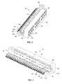
- Figure 2 is a front perspective view of the RF module shown in Figure 1 .
- Figure 3 is a rear perspective view of the RF module.
- Figure 4 illustrates a cable assembly for use with the RF module.
- Figure 5 is an exploded rear perspective view of a portion of the RF module.
- Figure 6 is a rear perspective view of a portion of the RF module.
- Figure 7 is a rear perspective view of a portion of the RF module.
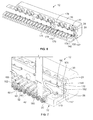
- Figure 8 is a rear perspective view of an alternative RF module.
- Figure 9 is a rear perspective view of a portion of the RF module shown in Figure 8 .
- Figure 10 is a front perspective view of a portion of the RF module shown in Figure 8 .
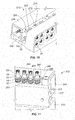
- Figure 11 is a bottom perspective view of a portion of the RF module shown in Figure 8 .
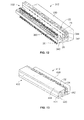
- Figure 12 is a rear perspective view of another alternative RF module.
- Figure 13 is a rear perspective view of yet another alternative RF module.
- Figure 14 is a sectional view of a cavity of the RF module shown in Figure 13 .
- Figure 15 is a bottom perspective view of a portion of the RF module shown in Figure 13 .
- Figure 16 is a side view of another alternative RF module.
- Figure 17 is a rear perspective view of an alternative RF module.
- Figure 18 is a rear perspective view of an alternative RF module.
- Figure 19 is a cross-sectional view of the RF module shown in Figure 18 .
- an RF module is provided that is configured to be coupled to a backplane module.
- the RF module includes a front housing that has walls that define connector cavities.
- the walls include a rear wall that has a plurality of openings therethrough.
- the connector cavities are open opposite the rear wall to receive electrical connectors.
- the RF module also includes RF cable assemblies having front end connectors and rear end connectors that are connected by corresponding cables.
- the front and rear end connectors are coaxial connectors.
- the front end connectors are received in corresponding connector cavities through corresponding openings.
- the RF module includes a connector holder extending from the front housing rearward of the rear wall. The connector holder holds the rear end connectors such that the rear end connectors are simultaneously pluggable into corresponding board connectors of the backplane module.
- an RF module configured to be coupled to a backplane module.
- the RF module has a front housing that has a plurality of connector cavities and a rear wall that has a plurality of openings therethrough to corresponding connector cavities.
- the front housing has a base extending rearward from the rear wall.
- the RF module has cable assemblies having front end connectors and rear end connectors that are connected by corresponding cables.
- the front and rear end connectors are coaxial connectors.
- the front end connectors are received in corresponding connector cavities through corresponding openings.
- the rear end connectors have cable ends and mating ends with a flange therebetween.
- a connector holder is separately provided from, and coupled to, the base.
- the connector holder has a plurality of cylindrical bores that receive the cable ends of the rear end connectors.
- the mating ends of the rear end connectors extend rearward from the connector holders such that the mating ends of the rear end connectors are configured to be gang loaded into corresponding board connectors of the backplane module.
- a board connector system having a backplane module that includes a frame, a backplane circuit board held by the frame, and a plurality of board connectors that are terminated to the backplane circuit board.
- the board connector system also includes a daughtercard module having a housing and a plurality of electrical connectors held by the housing. The electrical connectors are one of board mounted connectors or cable mounted connectors.
- the board connector system also includes an RF module coupled to the frame and interconnecting the board connectors of the backplane module with corresponding electrical connectors of the daughtercard module.
- the RF module includes RF cable assemblies that have front end connectors and rear end connectors connected by corresponding cables. The front and rear end connectors are coaxial connectors.
- the front end connectors are connected to corresponding electrical connectors of the daughtercard module.
- the rear end connectors are connected to corresponding board connectors of the backplane module.
- the RF module further includes a front housing that has a plurality of connector cavities that receive and hold corresponding front end connectors.
- the RF module further includes a connector holder that has a plurality of cylindrical bores that receive the rear end connectors. The rear end connectors extend rearward from the connector holder such that the rear end connectors are configured to be gang loaded into corresponding board connectors of the backplane module.
- FIG. 1 illustrates an electrical connector system 10 including a backplane module 11, an RF module 12 and a daughtercard module 13 formed in accordance with an exemplary embodiment.
- the electrical connector system 10 utilizes coaxial cables and coaxial connectors for interconnecting electronic devices and peripheral systems. While the electrical connector system 10 is illustrated and described as being used within a backplane system that uses the RF module 12 to interconnect the daughtercard module 13 with the backplane module 11, it is realized that the RF module 12 may be used in other applications to interconnect other devices or systems.
- the RF module 12 is usable with any system that interconnects coaxial connectors and/or coaxial cables.
- the RF module 12 is particularly useful in systems that interconnect multiple coaxial connectors simultaneously.
- the electrical connector system 10 may be used within a rugged environment, such as in a military or aeronautical application in which the components of the electrical connector system 10 may be subject to vibration and/or shock.
- One particular application is use in a jammer system used for jamming other signals, such as cell phone signals or other wireless signals.
- the backplane module 11 includes a frame 14, a backplane circuit board 15 held by the frame 14, and a plurality of board connectors 16 terminated to the backplane circuit board 15.
- the frame 14 may hold multiple backplane circuit boards 15.
- the board connectors 16 are coaxial connectors having an inner conductor (not shown) coaxially disposed within an outer conductor, with a dielectric material (not shown) separating the inner and outer conductors.
- the board connectors 16 may be SMP or SMPM type connectors, such as those commercially available from Tyco Electronics Ltd. Other types of connectors may be used in alternative embodiments.
- the board connectors 16 are receptacle connectors that receive jack connectors therein.
- the board connectors 16 may be smooth bore receptacle connectors or may be full detent receptacle connectors.
- the board connectors 16 may be right angle connectors or straight connectors terminated to the backplane circuit board 15.
- the board connectors 16 may be terminated to ends of cables rather than directly to the backplane circuit board 15 in alternative embodiments.
- the daughtercard module 13 includes a housing 17 and a plurality of electrical connectors 18 held by the housing 17. Any number of electrical connectors 18 may be utilized depending on the particular application.
- the daughtercard module 13 includes a daughtercard circuit board 19, with the housing 17 mounted to the daughtercard circuit board 19. Alternatively, the daughtercard circuit board 19 may be held within the housing 17. The electrical connectors 18 are terminated to the daughtercard circuit board 19.
- the electrical connectors 18 are coaxial connectors having an inner conductor (not shown) coaxially disposed within an outer conductor, with a dielectric material (not shown) separating the inner and outer conductors.
- the electrical connectors 18 may be SMP or SMPM type connectors or other types of connectors.
- the electrical connectors 18 are receptacle connectors that receive jack connectors therein.
- the electrical connectors 18 may be smooth bore receptacle connectors or may be full detent receptacle connectors.
- the electrical connectors 18 may be right angle connectors or straight connectors terminated to the daughtercard circuit board 19.
- the daughtercard module 13 may not include a daughtercard circuit board 19, but rather the electrical connectors 18 may be cable mounted connectors rather than board mounted connectors.
- the RF module 12 is used to interconnect the board connectors 16 and the electrical connectors 18.
- the RF module 12 provides an interface to the backplane module 11 and the daughtercard module 13.
- the backplane module 11 has a mating interface 20 (defined by the board connectors 16) and the daughtercard module 13 has a mating interface 21 (defined by the electrical connectors 18) that is different than the mating interface 20.
- the daughtercard module 13 cannot be mated directly to the backplane module 11.
- the electrical connectors 18 are grouped together in groups and provided in two rows, while the board connectors 16 are arranged in a single row, with each of the board connectors 16 being spaced apart by a common spacing distance. Other configurations are possible in alternative embodiments.
- the RF module 12 includes a plurality of cable assemblies 22 having front end connectors 24 and rear end connectors 26, with cables 28 routed between corresponding front and rear end connectors 24, 26.
- the front and rear end connectors 24, 26 are coaxial connectors having an inner conductor (not shown) coaxially disposed within an outer conductor, with a dielectric material (not shown) separating the inner and outer conductors.
- the front and rear end connectors 24, 26 may be SMP or SMPM type connectors or other types of connectors.
- the front and rear end connectors 24, 26 are jack connectors configured to be received in receptacle connectors.
- the front and rear end connectors 24, 26 may be right angle connectors or straight connectors terminated to ends of the cables 28.
- the front end connectors 24 are configured to be mated with the electrical connectors 18 of the daughtercard module 13.
- the rear end connectors 26 are configured to be mated with the board connectors 16 of the backplane module 11.
- the electrical connectors 18 are held by the housing 17 and simultaneously mated to the RF module 12 such that all of the electrical connectors 18 are mated with the front end connectors 24 as the daughtercard module 13 is coupled to the RF module 12.
- the rear end connectors 26 are held by the RF module 12 and simultaneously mated to the backplane module 11 such that all of the rear end connectors 26 are mated with the board connectors 16 as the RF module 12 is coupled to the backplane module 11. Having multiple connectors mated at the same time reduces the assembly time.
- FIG 2 is a front perspective view of the RF module 12.
- Figure 3 is a rear perspective view of the RF module 12.
- the RF module 12 includes a front housing 30 that holds the front end connectors 24.
- the RF module 12 includes a connector holder 32 extending rearward from the front housing 30.
- the connector holder 32 holds the rear end connectors 26 such that the rear end connectors 26 may be simultaneously plugged into the board connectors 16 (shown in Figure 1 ).
- Figure 4 illustrates one of the cable assemblies 22 for use with the RF module 12.
- the cable 28 extends between the front and rear end connectors 24, 26.
- the front and rear end connectors 24, 26 may be similar to one another, and the description hereafter generally refers to the rear end connector 26, it being realized that the front end connector 24 includes similar features.
- the rear end connector 26 includes a shell 40 extending along a central longitudinal axis 42 between a mating end 44 and a cable end 46.
- the shell 40 defines a shell cavity 48.
- the rear end connector 26 includes a center contact 50 held within the shell cavity 48.
- a dielectric body (not shown) is positioned between the shell 40 and the contact 50.
- the shell 40 is formed from a conductive material, such as a metal material, and the dielectric body electrically separates the contact 50 and the shell 40.
- a spring 54 (shown in Figure 9 ) may concentrically surround a portion of the shell 40. The spring 54 is used to preload the rear end connector 26 against the connector holder 32 (shown in Figure 2 ) or another structure.
- the front end connector 24 may also include a spring that is used to preload the front end connector 24 within the front housing 30 (shown in Figure 2 ) for mating with the electrical connector 18 (shown in Figure 1 ).
- the shell 40 is cylindrical in shape.
- a front flange 60 extends radially outward from the shell 40.
- a rear flange 62 extends radially outward from the shell 40 rearward of the front flange 60.
- a gap 64 is defined between the front and rear flanges 60, 62.
- the shell 40 is tapered or stepped at the mating end 44.
- the shell 40 includes a tip portion 66 configured to be received within the board connector 16.
- the tip portion 66 includes a plurality of segments 68 that are flexible and movable with respect to one another, such as to secure the shell 40 within the receptacle defined by the board connector 16.
- the front housing 30 includes a plurality of walls defining connector cavities 70.
- the front housing 30 extends between a mating end 72 and a rear wall 74 on a back side of the front housing 30. Some of the walls define interior walls 76 that separate adjacent connector cavities.
- the connector cavities 70 may be cylindrical in shape.
- the front housing 30 may be received in the frame 14 (shown in Figure 1 ).
- multiple RF modules 12 may be held proximate one another within the frame 14.
- the rear wall 74 includes a plurality of openings (not shown) therethrough that provide access to the connector cavities 70.
- the front end connectors 24 extend through the openings in the rear wall 74 into the connector cavities 70 for mating with the electrical connectors 18 (shown in Figure 1 ).
- the front housing 30 includes a base 80 extending rearward from the rear wall 74. The base 80 is provided below the cable assemblies 22.
- the connector holder 32 is separately provided from, and coupled to, the base 80 of the front housing 30.
- the connector holder 32 is used to hold the rear end connectors 26 for mating with the board connectors 16 of the backplane module 11.
- the connector holder 32 orients the rear end connectors 26 for gang loading the rear end connectors 26 into the board connectors 16 during assembly.
- each of the rear end connectors 26 are arranged in a single row.
- the connector holder 32 holds the rear end connectors 26 such that the mating ends 72 are coplanar with one another for simultaneously loading the rear end connectors 26 into the board connectors 16.
- the connector holder 32 defines a strain relief component for providing strain relief for the cables 28.
- the cables 28 may be routed through the connector holder 32 to resist harmful movement of the cables 28 which would put undue stress or strain on the connection between the cables 28 and the front end connectors 24 and/or rear end connectors 26.
- the connector holder 32 may also orient the cables 28 in proper positions such that the front end connectors 24 and/or rear end connectors 26 are properly positioned for mating with the electrical connectors 18 and board connectors 16, respectively.
- the connector holder 32 includes multiple pieces that may be coupled together and/or to the front housing 30.
- the connector holder 32 includes a base holder 140, a central plate 142 and a top cover 144.
- the base holder 140 is coupled to the base 80.
- the base holder 140 holds the rear end connectors 26.
- the central plate 142 is coupled to the front housing 30 on top of the base holder 140.
- the cables 28 extending from the front end connectors 24 in the lower row extend between the base holder 140 and the central plate 142.
- the top cover 144 is coupled to the central plate 142 above the central plate 142.
- the cables 28 extending from the front end connectors 24 in the upper row are held between the central plate 142 and the top cover 144.
- the connector holder 32 may include other components in alternative embodiments.
- the connector holder 32 may be provided without the top cover 144 and/or the central plate 142.
- FIG 5 is an exploded rear perspective view of a portion of the RF module 12 showing the base holder 140 poised for mounting to the front housing 30. Portions of the cable assemblies 22, namely the rear end connectors 26 (shown in Figures 2 and 3 ), and portions of the cables 28 have been removed for clarity.
- the base 80 includes a rear edge 146 and plurality of grooves 148 formed in the top surface thereof.
- the grooves 148 are configured to receive shells 40 (shown in Figure 4 ) of corresponding rear end connectors 26.
- the base holder 140 includes a plate 150 and a lip 152 at a rear of the plate 150.
- the lip 152 extends downward from the plate 150.
- the base holder 140 may be coupled to the base 80 such that the plate 150 rests on the top of the base 80 and the lip 152 extends along the rear edge 146.
- the plate 150 includes a plurality of pockets 154 at a front of the base holder 140.
- the pockets 154 are positioned to be aligned with the openings through the rear wall 74 of the front housing 30 associated with the lower row.
- the pockets 154 are configured to receive the cables 28 and provide a space for the cables 28 to pass through the connector holder 32.
- the pockets 154 support the cables 28 and the hold the cables 28 in position with respect to the openings in the rear wall 74.
- the pockets 154 resist side to side movement of the cables 28 to hold the cables 28 along longitudinal axes extending between the front end connectors 24 and the pockets 154.
- the base holder 140 includes a plurality of cylindrical bores 160 formed in the plate 150 and the lip 152.
- the cylindrical bores 160 receive the rear end connectors 26.
- the cylindrical bores 160 are sized substantially the same as the shells 40 of the rear end connectors 26 such that the rear end connectors 26 can be held within the bores 160.
- the base holder 140 includes cable slots 162 along a top 164 of the corresponding bores 160.
- the cable slots 162 are open to the bores 160.
- the cable slots 162 extend from the rear of the base holder 140 such that the cable slots 162 are open at the rear of the base holder 140.
- the cables 28 are configured to be received in the cable slots 162 such that the cables 28 may extend from above the base holder 140 into the bores 160.
- the cables 28 may be moveable longitudinally within the cable slots 162, such as to allow shifting or moving of the rear end connectors 26 within the bores 160.
- Figure 6 is a rear perspective view of a portion of the RF module 12 showing the base holder 140 and the central plate 142 coupled to the front housing 30. Portions of the cable assemblies 22 have been removed for clarity. The central plate 142 is shown mounted on top of the base holder 140.
- the central plate 142 includes a top 170 and a bottom 172.
- the central plate 142 has pockets 174 in the top 170 and pockets 176 in the bottom 172.
- the pockets 174 in the top 170 are aligned with the front end connectors 24 held in the upper row of the front housing 30.
- the pockets 176 in the bottom 172 are aligned with the front end connectors 24 held in the lower row of the front housing 30.
- the pockets 174, 176 receive the cables 28 extending from the front end connectors 24.
- the pockets 174, 176 resist side to side movement of the cables 28 and are configured to hold the cables 28 along longitudinal axes between the front end connectors 24 and the central plate 142.
- the pockets 176 in the bottom 172 are aligned with the pockets 154 in the base holder 140.
- the pockets 154, 176 cooperate to circumferentially surround the cables 28 extending from the front end connectors 24 in the lower row.
- the bottom 172 may rest upon the top of the plate 150 at or proximate to the front of the base holder 140.
- the cable assemblies associated with the lower row are fished into the pockets 154 in the base holder 140.
- the central plate 142 is then mounted above the base holder 140 to capture the cables 28 within the pockets 154, 176.
- the central plate 142 is mounted to the front housing 30 using mounting blocks 178 and fasteners (not shown) that secure the central plate 142 to the front housing 30.
- the central plate 142 may be secure to the base holder 140.
- the cable assemblies 22 in the upper row are then positioned over the top 170 of the central plate 142 such that the cables 28 rest in the pockets 174.
- FIG. 7 is a rear perspective view of a portion of the RF module 12 showing the top cover 144 coupled to the central plate 142.
- the top cover 144 includes pockets 180 along a bottom 182 of the top cover 144.
- the top cover 144 is positioned over the central plate 142 such that the pockets 180 are aligned with the pockets 174 in the top 170 of the central plate 142.
- the cables 28 extending from the front end connectors 24 in the upper row extend through the pockets 180, 174.
- the top cover 144 and central plate 142 cooperate to hold the cables 28 therebetween.
- the connector holder 32 When the cables 28 are held between the top cover 144 and central plate 142, and when the cables 28 are held between the central plate 142 and the base holder 140, the connector holder 32 provides strain relief for the cables 28, such as at the termination between the cables 28 and the front end connectors 24.
- the connector holder 32 holds the cables 28 along parallel longitudinal axes to prevent rotation or tilting of the front end connectors 24 within front housing 30.
- the cables 28 extend through the connector holder 32 and are routed to the rear end connectors 26 through the cable slots 162.
- the rear end connectors 26 are loaded into the cylindrical bores 160 through the rear end of the base holder 140.
- the cables 28 are fished into the cable slots 162 as the rear end connectors 26 are loaded into the bores 160.
- the rear end connectors 26 are loaded into the bores 160 until the front flanges 60 engage the rear end of the base holder 140.
- the rear end connectors 26 may be generally held within the bores 160 by an interference fit between the shells 40 and the bores 160.
- the rear end connectors 26 are moveable within the bores 160 along the longitudinal axes 42 for mating with the board connector 16.
- the RF module 12 is coupled to the back plane module 11 (shown in Figure 1 ) such that the rear end connectors 26 are simultaneously loaded into the board connectors 16.
- the board connectors 16 may define smooth bore receptacle connectors wherein the rear end connectors 26 may be mated with the board connectors 16 by simply pressing the rear end connectors 26 into the board connectors 16, wherein all of the rear end connectors 26 may be simultaneously mated to the board connectors 16.
- the board connectors 16 may define full detent receptacle connectors, wherein the rear end connectors 26 need to be snapped into the board connectors 16.
- the force required to mate all of the rear end connectors 26 to such board connectors 16 may be too high to overcome without damaging the components.
- the rear end connectors 26 are initially loaded into the board connectors 16 during a gang loading process in which all of the rear end connectors 26 are simultaneously loaded into the board connectors 16 to an initial loaded position.
- a hand tool 190 may then be used to individually snap each of the rear end connectors 26 into the board connectors 16 by simply pressing the rear end connectors 26 in rearward direction.
- the hand tool 190 may be placed between the front flange 60 and the rear flange 62. Rotating the hand tool 190 may press the rear end connector 26 in a rearward direction to snap the tip portion 66 into the board connector 16 until the tip portion 66 passes the detent in the board connector 16.
- the connector holder 32 is used to align each of the rear end connectors 26 with the board connectors 16 such that the individual rear end connectors 26 do not need be positioned by hand during the assembly process. Rather, all of the rear end connectors 26 are initially loaded into the board connectors 16 and the rear end connectors 26 need to be moved along the longitudinal axes 42 only a short distance, such as less than 1mm, to fully mate the rear end connector 26 to the board connector 16. Assembly using the hand tool 190 may be quick and easy, greatly reducing the assembly time as compared to systems in which the rear end connectors 26 must be individually handled and aligned with the corresponding board connectors 16 and then mated with the board connector 16 before moving on to the next rear end connector.
- FIG 8 is a rear perspective view of an alternative RF module 212 that may be used to interconnect the backplane module 11 and the daughtercard module 13 (both shown in Figure 1 ).
- the RF module 212 includes a front housing 230 that may be substantially similar to the front housing 30 (shown in Figure 1 ).
- the RF module 212 holds a plurality of the cable assemblies 22.
- the front housing 230 holds the front end connectors 24 and a connector holder 232 holds the rear end connectors 26.
- the connector holder 232 orients the rear end connectors 26 for gang loading the rear end connectors 26 into the board connectors 16 (shown in Figure 1 ) during assembly.
- the connector holder 232 defines a strain relief component for providing strain relief for the cables 28.
- the connector holder 232 may also orient the cables 28 in proper positions such that the front end connectors 24 and/or rear end connectors 26 are properly positioned for mating with the electrical connectors 18 (shown in Figure 1 ) and board connectors 16, respectively.
- the connector holder 232 includes a base holder 240, a central plate 242 and a top cover 244.
- the base holder 240, central plate 242 and top cover 244 may be similar to the base holder 140, central plate 142 and top cover 144 (shown in Figure 3 ).
- the base holder 240 is coupled to the front housing 230 and holds the rear end connectors 26.
- the central plate 242 is coupled to the front housing 30 on top of the base holder 240.
- the top cover 244 is coupled to the central plate 242 above the central plate 242.
- the top cover 244 includes a top wall 246 and a rear wall 248 extending generally perpendicular to the top wall 246.
- the top wall 246 and rear wall 248 enclose the cable assemblies 22.
- the rear wall 248 engages the rear end connectors 26 at the base holder 240.
- the connector holder 232 may include other components in alternative embodiments.
- the connector holder 232 may be provided without the top cover 244 and/or the central plate 242.
- Figure 9 is a rear perspective view of a portion of the RF module 212. Only one cable 28 is illustrated extending entirely between the front end connector 24 and the rear end connector 26, while portions of the other cables have been removed for clarity.
- the springs 54 surround the shells 40 of the rear end connectors 26. The springs 54 are positioned between the front flange 60 and the base holder 240. The springs 54 may be compressed during mating with the board connectors 16 (shown in Figure 1 ). The springs 54 tend to force the rear end connectors 26 into the board connectors 16 to maintain connection therebetween.
- the base holder 240 includes a plate 250 and a lip 252 at a rear of the plate 250.
- the lip 252 extends downward from the plate 250.
- the plate 250 includes a plurality of pockets 254 at a front of the base holder 240.
- the pockets 254 are configured to receive the cables 28 and provide a space for the cables 28 to pass through the connector holder 232.
- the base holder 240 includes a plurality of cylindrical bores 260 formed in the plate 250 and the lip 252.
- the cylindrical bores 260 receive the rear end connectors 26.
- the base holder 240 includes cable slots 262 along a top 264 of the corresponding bores 260.
- the cable slots 262 are open to the bores 260.
- the cables 28 are configured to be received in the cable slots 262 such that the cables 28 may extend from above the base holder 240 into the bores 260.
- the cables 28 may be moveable longitudinally within the cable slots 262, such as to allow shifting or moving of the rear end connectors 26 within the bores 260.
- the central plate 242 is shown mounted on top of the base holder 240.
- the central plate 242 includes a top 270 and a bottom 272.
- the central plate 242 has pockets 274 in the top 270 and pockets 276 in the bottom 272.
- the pockets 274, 276 receive the cables 28 extending from the front end connectors 24 and rear end connectors 26, respectively.
- FIG 10 is a front perspective view of a portion of the RF module 212 showing the top cover 244 coupled to the central plate 242 and/or the base holder 240.
- the top cover 244 includes pockets 280 along a bottom 282 of the top cover 244.
- the top cover 244 is positioned over the central plate 242 such that the pockets 280 are aligned with the pockets 274 in the top 270 of the central plate 242.
- the cables 28 extending from the front end connectors 24 in the upper row extend through the pockets 280, 274.
- FIG 11 is a bottom perspective view of a portion of the RF module 212.
- the rear end connectors 26 are loaded into the cylindrical bores 260 through the rear end of the base holder 240.
- the springs 54 are positioned between the rear end of the base holder 240 and the front flange 60.
- the central plate 242 and top cover 244 are then positioned and secured to the base holder 240 and/or the front housing 230.
- the rear wall 248 extends to, and engages, the rear end connectors 26.
- a lower edge 284 of the rear wall 248 includes grooves 286 formed therein that are sized and shaped to receive the shells 40 of the rear end connectors 26.
- the front flanges 60 engage an inner surface 288 of the rear wall 248.
- the springs 54 may be at least partially compressed to preload the springs 54 to be biased outward for mating with the board connectors 16.
- the rear wall 248 is positioned between the front flange 60 and the rear flange 62.
- a gap 290 is defined between the rear flange 62 and the rear wall 248.
- the gap 290 allows a predetermined amount of travel of the rear end connector 26 during mating with the board connector 16.
- the gap 290 may be approximately 1.0 mm, which allows 1.0 mm of travel during mating with the board connector 16.
- the RF module 212 is coupled to the back plane module 11 (shown in Figure 1 ) such that the rear end connectors 26 are simultaneously loaded into the board connectors 16.
- the board connectors 16 may define smooth bore receptacle connectors wherein the rear end connectors 26 may be mated with the board connectors 16 by simply pressing the rear end connectors 26 into the board connectors 16, wherein all of the rear end connectors 26 may be simultaneously mated to the board connectors 16.
- the springs 54 help push the rear end connectors 26 into the smooth bore board connectors 16. Assembly is quick and easy, greatly reducing the assembly time as compared to systems in which the rear end connectors 26 must be individually handled and aligned with the corresponding board connectors 16 and then mated with the board connector 16 before moving on to the next rear end connector.
- FIG 12 is a rear perspective view of an alternative RF module 312 that may be used to interconnect the backplane module 11 and the daughtercard module 13 (both shown in Figure 1 ).
- the RF module 312 includes a front housing 330 that may be substantially similar to the front housing 30 (shown in Figure 1 ).
- the RF module 312 holds a plurality of the cable assemblies 22, wherein portions of the cables 28 of the cable assemblies 22 have been removed for clarity.
- the front housing 330 holds the front end connectors 24 and a connector holder 332 holds the rear end connectors 26.
- the connector holder 332 orients the rear end connectors 26 for gang loading the rear end connectors 26 into the board connectors 16 (shown in Figure 1 ) during assembly.
- the connector holder 332 orients the rear end connectors 26 generally perpendicular to the front end connectors 24. For example, if the front end connectors 24 are oriented horizontally then the rear end connectors 26 are oriented generally vertically. Other orientations are possible in alternative embodiments.
- the connector holder 332 includes a base holder 340, a central plate 342 and a top cover 344.
- the base holder 340, central plate 342 and top cover 344 may be similar to the base holder 140, central plate 142 and top cover 144 (shown in Figure 3 ).
- the base holder 340 includes multiple pieces, such as an upper piece and a lower piece.
- the lower piece is mounted to the front housing 330 and the upper piece includes bores 360 that receive and hold the rear end connectors 26.
- the rear end connectors 26 may be held in the bores 360 without any springs.
- the rear end connectors 26 may be initially gang loaded into the board connectors (shown in Figure 1 ) and then snapped into final positions using the hand tool 190 (shown in Figure 7 ).
- FIG 13 is a rear perspective view of an alternative RF module 412 that may be used to interconnect the backplane module 11 and the daughtercard module 13 (both shown in Figure 1 ).
- the RF module 412 includes a front housing 430 that may be substantially similar to the front housing 30 (shown in Figure 1 ).
- the RF module 412 holds a plurality of the cable assemblies 22.
- the front housing 430 holds the front end connectors 24 and a connector holder 432 holds the rear end connectors 26.
- the connector holder 432 orients the rear end connectors 26 for gang loading the rear end connectors 26 into the board connectors 16 (shown in Figure 1 ) during assembly.
- the connector holder 432 orients the rear end connectors 26 generally perpendicular to the front end connectors 24. For example, if the front end connectors 24 are oriented horizontally then the rear end connectors 26 are oriented generally vertically. Other orientations are possible in alternative embodiments.
- the connector holder 432 includes a lower base holder 440, an upper base holder 441, a central plate 442 and a top cover 444.
- the lower base holder 440 is coupled to the front housing 430.
- the upper base holder 441 is coupled to the lower base holder 440 and together the upper and lower base holders 440, 441 hold the rear end connectors 26.
- the central plate 442 is coupled to the front housing 430 on top of the lower base holder 440.
- the top cover 444 is coupled to the central plate 442 above the central plate 442.
- the top cover 444 rests on the upper base holder 441.
- the connector holder 432 may include other components in alternative embodiments.
- the connector holder 432 may be provided without the top cover 444 and/or the central plate 442.
- FIG 14 is a sectional view of a portion of the RF module 412. Portions of the cable assemblies 22 have been removed for clarity.
- the lower base holder 440 includes a main body 446 and a lip 448 extending from the main body 446.
- the lip 448 includes a plurality of channels 450 that have an open front.
- the lip 448 has an inner surface 452 and an outer surface 454.
- the channels 450 are configured to receive the rear end connectors 26 therein.
- the upper base holder 441 includes a main body 456 and a plurality of fingers 458 extending forward from the main body 456.
- the fingers 458 have cylindrical bores 460 therebetween with channels 462 forward of, and open to, the bores 460.
- the fingers 458 have an inner surface 464 and an outer surface 466.
- the bores 460 are configured to receive the rear end connectors 26 therein.
- the channels 462 provide a space for the cables 28 to be routed to the rear end connectors 26 from the central plate 442.
- Figure 15 is a bottom perspective view of a portion of the RF module 412.
- the springs 54 surround the shells 40 of the rear end connectors 26.
- the springs 54 are positioned between the front flange 60 and the upper base holder 441.
- the springs 54 may be compressed during mating with the board connectors 16 (shown in Figure 1 ).
- the springs 54 tend to force the rear end connectors 26 into the board connectors 16 to maintain connection therebetween.
- the rear end connectors 26 are loaded into the cylindrical bores 460 (shown in Figure 14 ) through the bottom of the upper base holder 441.
- the cables 28 may be passed through the channels 462 (shown in Figure 14 ) into the bores 460 and then the cable ends 46 (shown in Figure 4 ) loaded through the bores 460.
- the springs 54 are positioned between the outer surface 466 of the upper base holder 441 and the front flange 60.
- the front flange 60 rests on the inner surface 452 of the lower base holder 440.
- the springs 54 may be at least partially compressed to preload the springs 54 to be biased outward for mating with the board connectors 16.
- the lip 448 is positioned between the front flange 60 and the rear flange 62.
- a gap 490 is defined between the rear flange 62 and the lip 448.
- the gap 490 allows a predetermined amount of travel of the rear end connector 26 during mating with the board connector 16.
- the gap 490 may be approximately 1.0 mm, which allows 1.0 mm of travel during mating with the board connector 16.
- the RF module 412 is coupled to the back plane module 11 (shown in Figure 1 ) such that the rear end connectors 26 are simultaneously loaded into the board connectors 16.
- the board connectors 16 may define smooth bore receptacle connectors wherein the rear end connectors 26 may be mated with the board connectors 16 by simply pressing the rear end connectors 26 into the board connectors 16, wherein all of the rear end connectors 26 may be simultaneously mated to the board connectors 16.
- the springs 54 help push the rear end connectors 26 into the smooth bore board connectors 16. Assembly is quick and easy, greatly reducing the assembly time as compared to systems in which the rear end connectors 26 must be individually handled and aligned with the corresponding board connectors 16 and then mated with the board connector 16 before moving on to the next rear end connector.
- FIG 16 is a side view of another alternative RF module 512 that may be used to interconnect the backplane module 11 and the daughtercard module 13 (both shown in Figure 1 ).
- the RF module 512 includes a front housing 530 that may be substantially similar to the front housing 30 (shown in Figure 1 ).
- the RF module 512 holds a plurality of the cable assemblies 22.
- the front housing 530 holds the front end connectors 24 and a connector holder 532 holds rear end connectors 526.
- the rear end connectors 526 are right angle coaxial connectors, as opposed to the straight coaxial connectors shown in Figure 4 .
- the connector holder 532 orients the rear end connectors 526 for gang loading the rear end connectors 526 into the board connectors 16 (shown in Figure 1 ) during assembly.
- the connector holder 532 also holds the cables 28 and may provide strain relief.
- FIG 17 is a rear perspective view of an alternative RF module 612 that may be used to interconnect the backplane module 11 and the daughtercard module 13 (both shown in Figure 1 ).
- the RF module 612 includes a front housing 630 that may be substantially similar to the front housing 30 (shown in Figure 1 ).
- the RF module 612 holds a plurality of cable assemblies 622, wherein portions of the cables 28 of the cable assemblies 622 have been removed for clarity.
- the front housing 630 holds the front end connectors 24 and a connector holder 632 holds rear end connectors 626.
- the rear end connectors 626 are right angle coaxial connectors.
- the rear end connectors 626 generally extend along a longitudinal axis 628 and the cable 28 extends into the rear end connector 626 from a direction perpendicular to the longitudinal axis 628.
- the connector holder 632 orients the rear end connectors 626 for gang loading the rear end connectors 626 into the board connectors 16 (shown in Figure 1 ) during assembly.
- the connector holder 632 orients the rear end connectors 626 generally perpendicular to the front end connectors 24. For example, if the front end connectors 24 are oriented horizontally then the rear end connectors 626 are oriented generally vertically. Other orientations are possible in alternative embodiments.
- the connector holder 632 includes a base holder 640, a central plate 642 and a top cover 644.
- the base holder 640, central plate 642 and top cover 644 may be similar to the base holder 140, central plate 142 and top cover 144 (shown in Figure 3 ).
- the base holder 640 is mounted to the front housing 630 and includes bores 660 that receive and hold the rear end connectors 626.
- the rear end connectors 626 may be held in the bores 660 without any springs.
- the rear end connectors 626 may be initially gang loaded into the board connectors (shown in Figure 1 ) and then snapped into final positions using a hand tool (not shown) or by pressing down on a top surface 662 of the rear end connectors 626, such as by using a thumb.
- FIG 18 is a rear perspective view of an alternative RF module 712 that may be used to interconnect a backplane module 711 and the daughtercard module 13 (shown in Figure 1 ).
- the RF module 712 includes a front housing 730 that may be substantially similar to the front housing 30 (shown in Figure 1 ).
- the RF module 712 holds a plurality of the cable assemblies 22.
- the front housing 730 holds the front end connectors 24 and a connector holder 732 holds the rear end connectors 26.
- the connector holder 732 orients the rear end connectors 26 for gang loading the rear end connectors 26 into board connectors 716 of the backplane module 711 during assembly.
- the connector holder 732 orients the rear end connectors 26 generally perpendicular to the front end connectors 24. For example, if the front end connectors 24 are oriented horizontally then the rear end connectors 26 are oriented generally vertically. Other orientations are possible in alternative embodiments.
- the connector holder 732 is formed integral with the front housing 730.
- the connector holder 732 includes a base holder 740 that has bores 760 that receive and hold the rear end connectors 26.
- the rear end connectors 26 may be held in the bores 760 (shown in Figure 19 ) without any springs.
- the rear end connectors 26 may be initially gang loaded into the board connectors 716 and then snapped into final positions using the hand tool (not shown). Alternatively, the rear end connectors 26 may be pressed into the board connectors 716 and held in contact therewith using springs.
- Figure 19 is a cross-sectional view of the RF module 712 showing the rear end connectors 26 held in the connector holder 732.
Landscapes
- Details Of Connecting Devices For Male And Female Coupling (AREA)
- Coupling Device And Connection With Printed Circuit (AREA)
- Connector Housings Or Holding Contact Members (AREA)
Abstract
Description
- The subject matter herein relates generally to electrical connector assemblies.
- Due to their favorable electrical characteristics, coaxial cables and connectors have grown in popularity for interconnecting electronic devices and peripheral systems. The connectors include an inner conductor coaxially disposed within an outer conductor, with a dielectric material separating the inner and outer conductors. A typical application utilizing coaxial cable connectors is a radiofrequency (RF) application having RF connectors designed to work at radio frequencies in the UHF and/or VHF range.
- Typically, one or more connectors are mounted to a circuit board of an electronic device at an input/output port of the device and extends through an exterior housing of the device for connection with a coaxial cable connector. Some systems include a plurality of connectors held in a common housing. One particular example of a system that uses multiple connectors is a backplane module having a plurality of board mounted connectors with a separate mating assembly for mating with a daughtercard module. The mating assembly includes a housing holding a plurality of coaxial cable connectors, which are connected to the board mounted connectors by a cable assembly having cable end connectors individually terminated to corresponding board mounted connectors. The daughtercard module is mated with the mating assembly.
- Known backplane systems using RF connectors are not without disadvantages. For instance, each of the cable end connectors need to be individually and separately mated with the board connectors, which is time consuming and increases the cost of assembly. Additionally, the spacing between the housing of the mating assembly and the board connectors may be very small, such as less than 25mm (one inch), making the assembly process difficult and time consuming. Having a large number of connections to make also increases the time and complexity.
- The problem to be solved is a need for an RF module that may be mated with a backplane module in a cost effective, timely and reliable manner.
- The solution is provided by an RF module that is configured to be coupled to a backplane module. The RF module includes a front housing that has walls that define connector cavities. The walls include a rear wall that has a plurality of openings therethrough. The connector cavities are open opposite the rear wall to receive electrical connectors. The RF module also includes RF cable assemblies having front end connectors and rear end connectors that are connected by corresponding cables. The front and rear end connectors are coaxial connectors. The front end connectors are received in corresponding connector cavities through corresponding openings. The RF module includes a connector holder extending from the front housing rearward of the rear wall. The connector holder holds the rear end connectors such that the rear end connectors are simultaneously pluggable into corresponding board connectors of the backplane module.
- The invention will now be described by way of example with reference to the accompanying drawings in which:
-
Figure 1 illustrates an electrical connector system formed in accordance with an exemplary embodiment including a backplane module, an RF module and a daughtercard module. -
Figure 2 is a front perspective view of the RF module shown inFigure 1 . -
Figure 3 is a rear perspective view of the RF module. -
Figure 4 illustrates a cable assembly for use with the RF module. -
Figure 5 is an exploded rear perspective view of a portion of the RF module. -
Figure 6 is a rear perspective view of a portion of the RF module. -
Figure 7 is a rear perspective view of a portion of the RF module. -
Figure 8 is a rear perspective view of an alternative RF module. -
Figure 9 is a rear perspective view of a portion of the RF module shown inFigure 8 . -
Figure 10 is a front perspective view of a portion of the RF module shown inFigure 8 . -
Figure 11 is a bottom perspective view of a portion of the RF module shown inFigure 8 . -
Figure 12 is a rear perspective view of another alternative RF module. -
Figure 13 is a rear perspective view of yet another alternative RF module. -
Figure 14 is a sectional view of a cavity of the RF module shown inFigure 13 . -
Figure 15 is a bottom perspective view of a portion of the RF module shown inFigure 13 . -
Figure 16 is a side view of another alternative RF module. -
Figure 17 is a rear perspective view of an alternative RF module. -
Figure 18 is a rear perspective view of an alternative RF module. -
Figure 19 is a cross-sectional view of the RF module shown inFigure 18 . - In one embodiment, an RF module is provided that is configured to be coupled to a backplane module. The RF module includes a front housing that has walls that define connector cavities. The walls include a rear wall that has a plurality of openings therethrough. The connector cavities are open opposite the rear wall to receive electrical connectors. The RF module also includes RF cable assemblies having front end connectors and rear end connectors that are connected by corresponding cables. The front and rear end connectors are coaxial connectors. The front end connectors are received in corresponding connector cavities through corresponding openings. The RF module includes a connector holder extending from the front housing rearward of the rear wall. The connector holder holds the rear end connectors such that the rear end connectors are simultaneously pluggable into corresponding board connectors of the backplane module.
- In another embodiment, an RF module is provided that is configured to be coupled to a backplane module. The RF module has a front housing that has a plurality of connector cavities and a rear wall that has a plurality of openings therethrough to corresponding connector cavities. The front housing has a base extending rearward from the rear wall. The RF module has cable assemblies having front end connectors and rear end connectors that are connected by corresponding cables. The front and rear end connectors are coaxial connectors. The front end connectors are received in corresponding connector cavities through corresponding openings. The rear end connectors have cable ends and mating ends with a flange therebetween. A connector holder is separately provided from, and coupled to, the base. The connector holder has a plurality of cylindrical bores that receive the cable ends of the rear end connectors. The mating ends of the rear end connectors extend rearward from the connector holders such that the mating ends of the rear end connectors are configured to be gang loaded into corresponding board connectors of the backplane module.
- In a further embodiment, a board connector system is provided having a backplane module that includes a frame, a backplane circuit board held by the frame, and a plurality of board connectors that are terminated to the backplane circuit board. The board connector system also includes a daughtercard module having a housing and a plurality of electrical connectors held by the housing. The electrical connectors are one of board mounted connectors or cable mounted connectors. The board connector system also includes an RF module coupled to the frame and interconnecting the board connectors of the backplane module with corresponding electrical connectors of the daughtercard module. The RF module includes RF cable assemblies that have front end connectors and rear end connectors connected by corresponding cables. The front and rear end connectors are coaxial connectors. The front end connectors are connected to corresponding electrical connectors of the daughtercard module. The rear end connectors are connected to corresponding board connectors of the backplane module. The RF module further includes a front housing that has a plurality of connector cavities that receive and hold corresponding front end connectors. The RF module further includes a connector holder that has a plurality of cylindrical bores that receive the rear end connectors. The rear end connectors extend rearward from the connector holder such that the rear end connectors are configured to be gang loaded into corresponding board connectors of the backplane module.
-
Figure 1 illustrates anelectrical connector system 10 including abackplane module 11, anRF module 12 and adaughtercard module 13 formed in accordance with an exemplary embodiment. Theelectrical connector system 10 utilizes coaxial cables and coaxial connectors for interconnecting electronic devices and peripheral systems. While theelectrical connector system 10 is illustrated and described as being used within a backplane system that uses theRF module 12 to interconnect thedaughtercard module 13 with thebackplane module 11, it is realized that theRF module 12 may be used in other applications to interconnect other devices or systems. - The
RF module 12 is usable with any system that interconnects coaxial connectors and/or coaxial cables. TheRF module 12 is particularly useful in systems that interconnect multiple coaxial connectors simultaneously. Theelectrical connector system 10 may be used within a rugged environment, such as in a military or aeronautical application in which the components of theelectrical connector system 10 may be subject to vibration and/or shock. One particular application is use in a jammer system used for jamming other signals, such as cell phone signals or other wireless signals. - The
backplane module 11 includes aframe 14, abackplane circuit board 15 held by theframe 14, and a plurality ofboard connectors 16 terminated to thebackplane circuit board 15. Theframe 14 may hold multiplebackplane circuit boards 15. Theboard connectors 16 are coaxial connectors having an inner conductor (not shown) coaxially disposed within an outer conductor, with a dielectric material (not shown) separating the inner and outer conductors. Theboard connectors 16 may be SMP or SMPM type connectors, such as those commercially available from Tyco Electronics Ltd. Other types of connectors may be used in alternative embodiments. - In an exemplary embodiment, the
board connectors 16 are receptacle connectors that receive jack connectors therein. Theboard connectors 16 may be smooth bore receptacle connectors or may be full detent receptacle connectors. Theboard connectors 16 may be right angle connectors or straight connectors terminated to thebackplane circuit board 15. Theboard connectors 16 may be terminated to ends of cables rather than directly to thebackplane circuit board 15 in alternative embodiments. - The
daughtercard module 13 includes ahousing 17 and a plurality ofelectrical connectors 18 held by thehousing 17. Any number ofelectrical connectors 18 may be utilized depending on the particular application. Thedaughtercard module 13 includes adaughtercard circuit board 19, with thehousing 17 mounted to thedaughtercard circuit board 19. Alternatively, thedaughtercard circuit board 19 may be held within thehousing 17. Theelectrical connectors 18 are terminated to thedaughtercard circuit board 19. - The
electrical connectors 18 are coaxial connectors having an inner conductor (not shown) coaxially disposed within an outer conductor, with a dielectric material (not shown) separating the inner and outer conductors. Theelectrical connectors 18 may be SMP or SMPM type connectors or other types of connectors. Theelectrical connectors 18 are receptacle connectors that receive jack connectors therein. Theelectrical connectors 18 may be smooth bore receptacle connectors or may be full detent receptacle connectors. Theelectrical connectors 18 may be right angle connectors or straight connectors terminated to thedaughtercard circuit board 19. In an alternative embodiment, thedaughtercard module 13 may not include adaughtercard circuit board 19, but rather theelectrical connectors 18 may be cable mounted connectors rather than board mounted connectors. - The
RF module 12 is used to interconnect theboard connectors 16 and theelectrical connectors 18. TheRF module 12 provides an interface to thebackplane module 11 and thedaughtercard module 13. In an exemplary embodiment, thebackplane module 11 has a mating interface 20 (defined by the board connectors 16) and thedaughtercard module 13 has a mating interface 21 (defined by the electrical connectors 18) that is different than themating interface 20. As such, thedaughtercard module 13 cannot be mated directly to thebackplane module 11. In the illustrated embodiment, theelectrical connectors 18 are grouped together in groups and provided in two rows, while theboard connectors 16 are arranged in a single row, with each of theboard connectors 16 being spaced apart by a common spacing distance. Other configurations are possible in alternative embodiments. - The
RF module 12 includes a plurality ofcable assemblies 22 havingfront end connectors 24 andrear end connectors 26, withcables 28 routed between corresponding front andrear end connectors rear end connectors rear end connectors rear end connectors rear end connectors cables 28. - The
front end connectors 24 are configured to be mated with theelectrical connectors 18 of thedaughtercard module 13. Therear end connectors 26 are configured to be mated with theboard connectors 16 of thebackplane module 11. In an exemplary embodiment, theelectrical connectors 18 are held by thehousing 17 and simultaneously mated to theRF module 12 such that all of theelectrical connectors 18 are mated with thefront end connectors 24 as thedaughtercard module 13 is coupled to theRF module 12. In an exemplary embodiment, therear end connectors 26 are held by theRF module 12 and simultaneously mated to thebackplane module 11 such that all of therear end connectors 26 are mated with theboard connectors 16 as theRF module 12 is coupled to thebackplane module 11. Having multiple connectors mated at the same time reduces the assembly time. -
Figure 2 is a front perspective view of theRF module 12.Figure 3 is a rear perspective view of theRF module 12. TheRF module 12 includes afront housing 30 that holds thefront end connectors 24. TheRF module 12 includes aconnector holder 32 extending rearward from thefront housing 30. Theconnector holder 32 holds therear end connectors 26 such that therear end connectors 26 may be simultaneously plugged into the board connectors 16 (shown inFigure 1 ). -
Figure 4 illustrates one of thecable assemblies 22 for use with theRF module 12. Thecable 28 extends between the front andrear end connectors rear end connectors rear end connector 26, it being realized that thefront end connector 24 includes similar features. - The
rear end connector 26 includes ashell 40 extending along a centrallongitudinal axis 42 between amating end 44 and acable end 46. Theshell 40 defines ashell cavity 48. Therear end connector 26 includes acenter contact 50 held within theshell cavity 48. In an exemplary embodiment, a dielectric body (not shown) is positioned between theshell 40 and thecontact 50. In an exemplary embodiment, theshell 40 is formed from a conductive material, such as a metal material, and the dielectric body electrically separates thecontact 50 and theshell 40. Optionally, a spring 54 (shown inFigure 9 ) may concentrically surround a portion of theshell 40. Thespring 54 is used to preload therear end connector 26 against the connector holder 32 (shown inFigure 2 ) or another structure. Thefront end connector 24 may also include a spring that is used to preload thefront end connector 24 within the front housing 30 (shown inFigure 2 ) for mating with the electrical connector 18 (shown inFigure 1 ). - The
shell 40 is cylindrical in shape. Afront flange 60 extends radially outward from theshell 40. Arear flange 62 extends radially outward from theshell 40 rearward of thefront flange 60. Agap 64 is defined between the front andrear flanges - The
shell 40 is tapered or stepped at themating end 44. Theshell 40 includes atip portion 66 configured to be received within theboard connector 16. In an exemplary embodiment, thetip portion 66 includes a plurality ofsegments 68 that are flexible and movable with respect to one another, such as to secure theshell 40 within the receptacle defined by theboard connector 16. - Returning to
Figures 2 and 3 , thefront housing 30 includes a plurality of walls definingconnector cavities 70. Thefront housing 30 extends between amating end 72 and arear wall 74 on a back side of thefront housing 30. Some of the walls defineinterior walls 76 that separate adjacent connector cavities. Optionally, theconnector cavities 70 may be cylindrical in shape. In the illustrated embodiment, thefront housing 30 may be received in the frame 14 (shown inFigure 1 ). Optionally,multiple RF modules 12 may be held proximate one another within theframe 14. Therear wall 74 includes a plurality of openings (not shown) therethrough that provide access to theconnector cavities 70. Thefront end connectors 24 extend through the openings in therear wall 74 into theconnector cavities 70 for mating with the electrical connectors 18 (shown inFigure 1 ). Thefront housing 30 includes a base 80 extending rearward from therear wall 74. Thebase 80 is provided below thecable assemblies 22. - The
connector holder 32 is separately provided from, and coupled to, thebase 80 of thefront housing 30. Theconnector holder 32 is used to hold therear end connectors 26 for mating with theboard connectors 16 of thebackplane module 11. Theconnector holder 32 orients therear end connectors 26 for gang loading therear end connectors 26 into theboard connectors 16 during assembly. In an exemplary embodiment, each of therear end connectors 26 are arranged in a single row. Theconnector holder 32 holds therear end connectors 26 such that the mating ends 72 are coplanar with one another for simultaneously loading therear end connectors 26 into theboard connectors 16. In an exemplary embodiment, theconnector holder 32 defines a strain relief component for providing strain relief for thecables 28. For example, thecables 28 may be routed through theconnector holder 32 to resist harmful movement of thecables 28 which would put undue stress or strain on the connection between thecables 28 and thefront end connectors 24 and/orrear end connectors 26. Theconnector holder 32 may also orient thecables 28 in proper positions such that thefront end connectors 24 and/orrear end connectors 26 are properly positioned for mating with theelectrical connectors 18 andboard connectors 16, respectively. - The
connector holder 32 includes multiple pieces that may be coupled together and/or to thefront housing 30. In the illustrated embodiment, theconnector holder 32 includes abase holder 140, acentral plate 142 and atop cover 144. Thebase holder 140 is coupled to thebase 80. Thebase holder 140 holds therear end connectors 26. Thecentral plate 142 is coupled to thefront housing 30 on top of thebase holder 140. Thecables 28 extending from thefront end connectors 24 in the lower row extend between thebase holder 140 and thecentral plate 142. Thetop cover 144 is coupled to thecentral plate 142 above thecentral plate 142. Thecables 28 extending from thefront end connectors 24 in the upper row are held between thecentral plate 142 and thetop cover 144. Theconnector holder 32 may include other components in alternative embodiments. Optionally, theconnector holder 32 may be provided without thetop cover 144 and/or thecentral plate 142. -
Figure 5 is an exploded rear perspective view of a portion of theRF module 12 showing thebase holder 140 poised for mounting to thefront housing 30. Portions of thecable assemblies 22, namely the rear end connectors 26 (shown inFigures 2 and 3 ), and portions of thecables 28 have been removed for clarity. - The
base 80 includes arear edge 146 and plurality ofgrooves 148 formed in the top surface thereof. Thegrooves 148 are configured to receive shells 40 (shown inFigure 4 ) of correspondingrear end connectors 26. - The
base holder 140 includes aplate 150 and alip 152 at a rear of theplate 150. Thelip 152 extends downward from theplate 150. Thebase holder 140 may be coupled to the base 80 such that theplate 150 rests on the top of thebase 80 and thelip 152 extends along therear edge 146. Theplate 150 includes a plurality ofpockets 154 at a front of thebase holder 140. Thepockets 154 are positioned to be aligned with the openings through therear wall 74 of thefront housing 30 associated with the lower row. Thepockets 154 are configured to receive thecables 28 and provide a space for thecables 28 to pass through theconnector holder 32. Thepockets 154 support thecables 28 and the hold thecables 28 in position with respect to the openings in therear wall 74. Thepockets 154 resist side to side movement of thecables 28 to hold thecables 28 along longitudinal axes extending between thefront end connectors 24 and thepockets 154. - The
base holder 140 includes a plurality ofcylindrical bores 160 formed in theplate 150 and thelip 152. The cylindrical bores 160 receive therear end connectors 26. The cylindrical bores 160 are sized substantially the same as theshells 40 of therear end connectors 26 such that therear end connectors 26 can be held within thebores 160. Thebase holder 140 includescable slots 162 along a top 164 of the corresponding bores 160. Thecable slots 162 are open to thebores 160. In an exemplary embodiment, thecable slots 162 extend from the rear of thebase holder 140 such that thecable slots 162 are open at the rear of thebase holder 140. Thecables 28 are configured to be received in thecable slots 162 such that thecables 28 may extend from above thebase holder 140 into thebores 160. Optionally, thecables 28 may be moveable longitudinally within thecable slots 162, such as to allow shifting or moving of therear end connectors 26 within thebores 160. -
Figure 6 is a rear perspective view of a portion of theRF module 12 showing thebase holder 140 and thecentral plate 142 coupled to thefront housing 30. Portions of thecable assemblies 22 have been removed for clarity. Thecentral plate 142 is shown mounted on top of thebase holder 140. - The
central plate 142 includes a top 170 and a bottom 172. Thecentral plate 142 haspockets 174 in the top 170 andpockets 176 in the bottom 172. Thepockets 174 in the top 170 are aligned with thefront end connectors 24 held in the upper row of thefront housing 30. Thepockets 176 in the bottom 172 are aligned with thefront end connectors 24 held in the lower row of thefront housing 30. Thepockets cables 28 extending from thefront end connectors 24. Thepockets cables 28 and are configured to hold thecables 28 along longitudinal axes between thefront end connectors 24 and thecentral plate 142. When the central plate is mounted above thebase holder 140, thepockets 176 in the bottom 172 are aligned with thepockets 154 in thebase holder 140. Thepockets cables 28 extending from thefront end connectors 24 in the lower row. The bottom 172 may rest upon the top of theplate 150 at or proximate to the front of thebase holder 140. - During assembly, the cable assemblies associated with the lower row are fished into the
pockets 154 in thebase holder 140. Thecentral plate 142 is then mounted above thebase holder 140 to capture thecables 28 within thepockets central plate 142 is mounted to thefront housing 30 using mountingblocks 178 and fasteners (not shown) that secure thecentral plate 142 to thefront housing 30. Alternatively, thecentral plate 142 may be secure to thebase holder 140. Thecable assemblies 22 in the upper row are then positioned over the top 170 of thecentral plate 142 such that thecables 28 rest in thepockets 174. -
Figure 7 is a rear perspective view of a portion of theRF module 12 showing thetop cover 144 coupled to thecentral plate 142. Thetop cover 144 includespockets 180 along abottom 182 of thetop cover 144. Thetop cover 144 is positioned over thecentral plate 142 such that thepockets 180 are aligned with thepockets 174 in the top 170 of thecentral plate 142. Thecables 28 extending from thefront end connectors 24 in the upper row extend through thepockets top cover 144 andcentral plate 142 cooperate to hold thecables 28 therebetween. - When the
cables 28 are held between thetop cover 144 andcentral plate 142, and when thecables 28 are held between thecentral plate 142 and thebase holder 140, theconnector holder 32 provides strain relief for thecables 28, such as at the termination between thecables 28 and thefront end connectors 24. Theconnector holder 32 holds thecables 28 along parallel longitudinal axes to prevent rotation or tilting of thefront end connectors 24 withinfront housing 30. - The
cables 28 extend through theconnector holder 32 and are routed to therear end connectors 26 through thecable slots 162. During assembly, therear end connectors 26 are loaded into the cylindrical bores 160 through the rear end of thebase holder 140. Thecables 28 are fished into thecable slots 162 as therear end connectors 26 are loaded into thebores 160. Therear end connectors 26 are loaded into thebores 160 until thefront flanges 60 engage the rear end of thebase holder 140. Therear end connectors 26 may be generally held within thebores 160 by an interference fit between theshells 40 and thebores 160. In an exemplary embodiment, therear end connectors 26 are moveable within thebores 160 along thelongitudinal axes 42 for mating with theboard connector 16. - During mating, the
RF module 12 is coupled to the back plane module 11 (shown inFigure 1 ) such that therear end connectors 26 are simultaneously loaded into theboard connectors 16. In one embodiment, theboard connectors 16 may define smooth bore receptacle connectors wherein therear end connectors 26 may be mated with theboard connectors 16 by simply pressing therear end connectors 26 into theboard connectors 16, wherein all of therear end connectors 26 may be simultaneously mated to theboard connectors 16. - In another embodiment, the
board connectors 16 may define full detent receptacle connectors, wherein therear end connectors 26 need to be snapped into theboard connectors 16. The force required to mate all of therear end connectors 26 tosuch board connectors 16 may be too high to overcome without damaging the components. In such situation, therear end connectors 26 are initially loaded into theboard connectors 16 during a gang loading process in which all of therear end connectors 26 are simultaneously loaded into theboard connectors 16 to an initial loaded position. Ahand tool 190 may then be used to individually snap each of therear end connectors 26 into theboard connectors 16 by simply pressing therear end connectors 26 in rearward direction. For example, thehand tool 190 may be placed between thefront flange 60 and therear flange 62. Rotating thehand tool 190 may press therear end connector 26 in a rearward direction to snap thetip portion 66 into theboard connector 16 until thetip portion 66 passes the detent in theboard connector 16. - The
connector holder 32 is used to align each of therear end connectors 26 with theboard connectors 16 such that the individualrear end connectors 26 do not need be positioned by hand during the assembly process. Rather, all of therear end connectors 26 are initially loaded into theboard connectors 16 and therear end connectors 26 need to be moved along thelongitudinal axes 42 only a short distance, such as less than 1mm, to fully mate therear end connector 26 to theboard connector 16. Assembly using thehand tool 190 may be quick and easy, greatly reducing the assembly time as compared to systems in which therear end connectors 26 must be individually handled and aligned with the correspondingboard connectors 16 and then mated with theboard connector 16 before moving on to the next rear end connector. -
Figure 8 is a rear perspective view of analternative RF module 212 that may be used to interconnect thebackplane module 11 and the daughtercard module 13 (both shown inFigure 1 ). TheRF module 212 includes afront housing 230 that may be substantially similar to the front housing 30 (shown inFigure 1 ). TheRF module 212 holds a plurality of thecable assemblies 22. Thefront housing 230 holds thefront end connectors 24 and aconnector holder 232 holds therear end connectors 26. - The
connector holder 232 orients therear end connectors 26 for gang loading therear end connectors 26 into the board connectors 16 (shown inFigure 1 ) during assembly. Theconnector holder 232 defines a strain relief component for providing strain relief for thecables 28. Theconnector holder 232 may also orient thecables 28 in proper positions such that thefront end connectors 24 and/orrear end connectors 26 are properly positioned for mating with the electrical connectors 18 (shown inFigure 1 ) andboard connectors 16, respectively. - The
connector holder 232 includes abase holder 240, acentral plate 242 and atop cover 244. Thebase holder 240,central plate 242 andtop cover 244 may be similar to thebase holder 140,central plate 142 and top cover 144 (shown inFigure 3 ). - The
base holder 240 is coupled to thefront housing 230 and holds therear end connectors 26. Thecentral plate 242 is coupled to thefront housing 30 on top of thebase holder 240. Thetop cover 244 is coupled to thecentral plate 242 above thecentral plate 242. Thetop cover 244 includes atop wall 246 and arear wall 248 extending generally perpendicular to thetop wall 246. Thetop wall 246 andrear wall 248 enclose thecable assemblies 22. Therear wall 248 engages therear end connectors 26 at thebase holder 240. Theconnector holder 232 may include other components in alternative embodiments. Optionally, theconnector holder 232 may be provided without thetop cover 244 and/or thecentral plate 242. -
Figure 9 is a rear perspective view of a portion of theRF module 212. Only onecable 28 is illustrated extending entirely between thefront end connector 24 and therear end connector 26, while portions of the other cables have been removed for clarity. In the illustrated embodiment, thesprings 54 surround theshells 40 of therear end connectors 26. Thesprings 54 are positioned between thefront flange 60 and thebase holder 240. Thesprings 54 may be compressed during mating with the board connectors 16 (shown inFigure 1 ). Thesprings 54 tend to force therear end connectors 26 into theboard connectors 16 to maintain connection therebetween. - The
base holder 240 includes aplate 250 and alip 252 at a rear of theplate 250. Thelip 252 extends downward from theplate 250. Theplate 250 includes a plurality ofpockets 254 at a front of thebase holder 240. Thepockets 254 are configured to receive thecables 28 and provide a space for thecables 28 to pass through theconnector holder 232. - The
base holder 240 includes a plurality ofcylindrical bores 260 formed in theplate 250 and thelip 252. The cylindrical bores 260 receive therear end connectors 26. Thebase holder 240 includescable slots 262 along a top 264 of the corresponding bores 260. Thecable slots 262 are open to thebores 260. Thecables 28 are configured to be received in thecable slots 262 such that thecables 28 may extend from above thebase holder 240 into thebores 260. Optionally, thecables 28 may be moveable longitudinally within thecable slots 262, such as to allow shifting or moving of therear end connectors 26 within thebores 260. - The
central plate 242 is shown mounted on top of thebase holder 240. Thecentral plate 242 includes a top 270 and a bottom 272. Thecentral plate 242 haspockets 274 in the top 270 andpockets 276 in the bottom 272. Thepockets cables 28 extending from thefront end connectors 24 andrear end connectors 26, respectively. -
Figure 10 is a front perspective view of a portion of theRF module 212 showing thetop cover 244 coupled to thecentral plate 242 and/or thebase holder 240. Thetop cover 244 includespockets 280 along abottom 282 of thetop cover 244. Thetop cover 244 is positioned over thecentral plate 242 such that thepockets 280 are aligned with thepockets 274 in the top 270 of thecentral plate 242. Thecables 28 extending from thefront end connectors 24 in the upper row extend through thepockets -
Figure 11 is a bottom perspective view of a portion of theRF module 212. During assembly, therear end connectors 26 are loaded into the cylindrical bores 260 through the rear end of thebase holder 240. Thesprings 54 are positioned between the rear end of thebase holder 240 and thefront flange 60. Thecentral plate 242 andtop cover 244 are then positioned and secured to thebase holder 240 and/or thefront housing 230. Therear wall 248 extends to, and engages, therear end connectors 26. Alower edge 284 of therear wall 248 includesgrooves 286 formed therein that are sized and shaped to receive theshells 40 of therear end connectors 26. Thefront flanges 60 engage aninner surface 288 of therear wall 248. Optionally, when thetop cover 244 is coupled to thebase holder 240, thesprings 54 may be at least partially compressed to preload thesprings 54 to be biased outward for mating with theboard connectors 16. - The
rear wall 248 is positioned between thefront flange 60 and therear flange 62. In an exemplary embodiment, agap 290 is defined between therear flange 62 and therear wall 248. Thegap 290 allows a predetermined amount of travel of therear end connector 26 during mating with theboard connector 16. For example, thegap 290 may be approximately 1.0 mm, which allows 1.0 mm of travel during mating with theboard connector 16. - During mating, the
RF module 212 is coupled to the back plane module 11 (shown inFigure 1 ) such that therear end connectors 26 are simultaneously loaded into theboard connectors 16. In one embodiment, theboard connectors 16 may define smooth bore receptacle connectors wherein therear end connectors 26 may be mated with theboard connectors 16 by simply pressing therear end connectors 26 into theboard connectors 16, wherein all of therear end connectors 26 may be simultaneously mated to theboard connectors 16. Thesprings 54 help push therear end connectors 26 into the smoothbore board connectors 16. Assembly is quick and easy, greatly reducing the assembly time as compared to systems in which therear end connectors 26 must be individually handled and aligned with the correspondingboard connectors 16 and then mated with theboard connector 16 before moving on to the next rear end connector. -
Figure 12 is a rear perspective view of analternative RF module 312 that may be used to interconnect thebackplane module 11 and the daughtercard module 13 (both shown inFigure 1 ). TheRF module 312 includes afront housing 330 that may be substantially similar to the front housing 30 (shown inFigure 1 ). TheRF module 312 holds a plurality of thecable assemblies 22, wherein portions of thecables 28 of thecable assemblies 22 have been removed for clarity. Thefront housing 330 holds thefront end connectors 24 and aconnector holder 332 holds therear end connectors 26. - The
connector holder 332 orients therear end connectors 26 for gang loading therear end connectors 26 into the board connectors 16 (shown inFigure 1 ) during assembly. In the illustrated embodiment, theconnector holder 332 orients therear end connectors 26 generally perpendicular to thefront end connectors 24. For example, if thefront end connectors 24 are oriented horizontally then therear end connectors 26 are oriented generally vertically. Other orientations are possible in alternative embodiments. - The
connector holder 332 includes abase holder 340, acentral plate 342 and atop cover 344. Thebase holder 340,central plate 342 andtop cover 344 may be similar to thebase holder 140,central plate 142 and top cover 144 (shown inFigure 3 ). In the illustrated embodiment, thebase holder 340 includes multiple pieces, such as an upper piece and a lower piece. The lower piece is mounted to thefront housing 330 and the upper piece includesbores 360 that receive and hold therear end connectors 26. Optionally, therear end connectors 26 may be held in thebores 360 without any springs. Therear end connectors 26 may be initially gang loaded into the board connectors (shown inFigure 1 ) and then snapped into final positions using the hand tool 190 (shown inFigure 7 ). -
Figure 13 is a rear perspective view of analternative RF module 412 that may be used to interconnect thebackplane module 11 and the daughtercard module 13 (both shown inFigure 1 ). TheRF module 412 includes a front housing 430 that may be substantially similar to the front housing 30 (shown inFigure 1 ). TheRF module 412 holds a plurality of thecable assemblies 22. The front housing 430 holds thefront end connectors 24 and aconnector holder 432 holds therear end connectors 26. - The
connector holder 432 orients therear end connectors 26 for gang loading therear end connectors 26 into the board connectors 16 (shown inFigure 1 ) during assembly. In the illustrated embodiment, theconnector holder 432 orients therear end connectors 26 generally perpendicular to thefront end connectors 24. For example, if thefront end connectors 24 are oriented horizontally then therear end connectors 26 are oriented generally vertically. Other orientations are possible in alternative embodiments. - The
connector holder 432 includes alower base holder 440, anupper base holder 441, acentral plate 442 and atop cover 444. Thelower base holder 440 is coupled to the front housing 430. Theupper base holder 441 is coupled to thelower base holder 440 and together the upper andlower base holders rear end connectors 26. Thecentral plate 442 is coupled to the front housing 430 on top of thelower base holder 440. Thetop cover 444 is coupled to thecentral plate 442 above thecentral plate 442. Thetop cover 444 rests on theupper base holder 441. Theconnector holder 432 may include other components in alternative embodiments. Optionally, theconnector holder 432 may be provided without thetop cover 444 and/or thecentral plate 442. -
Figure 14 is a sectional view of a portion of theRF module 412. Portions of thecable assemblies 22 have been removed for clarity. Thelower base holder 440 includes amain body 446 and alip 448 extending from themain body 446. Thelip 448 includes a plurality ofchannels 450 that have an open front. Thelip 448 has aninner surface 452 and anouter surface 454. Thechannels 450 are configured to receive therear end connectors 26 therein. - The
upper base holder 441 includes amain body 456 and a plurality offingers 458 extending forward from themain body 456. Thefingers 458 havecylindrical bores 460 therebetween withchannels 462 forward of, and open to, thebores 460. Thefingers 458 have aninner surface 464 and anouter surface 466. Thebores 460 are configured to receive therear end connectors 26 therein. Thechannels 462 provide a space for thecables 28 to be routed to therear end connectors 26 from thecentral plate 442. -
Figure 15 is a bottom perspective view of a portion of theRF module 412. In the illustrated embodiment, thesprings 54 surround theshells 40 of therear end connectors 26. Thesprings 54 are positioned between thefront flange 60 and theupper base holder 441. Thesprings 54 may be compressed during mating with the board connectors 16 (shown inFigure 1 ). Thesprings 54 tend to force therear end connectors 26 into theboard connectors 16 to maintain connection therebetween. - During assembly, the
rear end connectors 26 are loaded into the cylindrical bores 460 (shown inFigure 14 ) through the bottom of theupper base holder 441. Thecables 28 may be passed through the channels 462 (shown inFigure 14 ) into thebores 460 and then the cable ends 46 (shown inFigure 4 ) loaded through thebores 460. Thesprings 54 are positioned between theouter surface 466 of theupper base holder 441 and thefront flange 60. Thefront flange 60 rests on theinner surface 452 of thelower base holder 440. Optionally, when theupper base holder 441 is coupled to thelower base holder 440, thesprings 54 may be at least partially compressed to preload thesprings 54 to be biased outward for mating with theboard connectors 16. - The
lip 448 is positioned between thefront flange 60 and therear flange 62. In an exemplary embodiment, agap 490 is defined between therear flange 62 and thelip 448. Thegap 490 allows a predetermined amount of travel of therear end connector 26 during mating with theboard connector 16. For example, thegap 490 may be approximately 1.0 mm, which allows 1.0 mm of travel during mating with theboard connector 16. - During mating, the
RF module 412 is coupled to the back plane module 11 (shown inFigure 1 ) such that therear end connectors 26 are simultaneously loaded into theboard connectors 16. In one embodiment, theboard connectors 16 may define smooth bore receptacle connectors wherein therear end connectors 26 may be mated with theboard connectors 16 by simply pressing therear end connectors 26 into theboard connectors 16, wherein all of therear end connectors 26 may be simultaneously mated to theboard connectors 16. Thesprings 54 help push therear end connectors 26 into the smoothbore board connectors 16. Assembly is quick and easy, greatly reducing the assembly time as compared to systems in which therear end connectors 26 must be individually handled and aligned with the correspondingboard connectors 16 and then mated with theboard connector 16 before moving on to the next rear end connector. -
Figure 16 is a side view of anotheralternative RF module 512 that may be used to interconnect thebackplane module 11 and the daughtercard module 13 (both shown inFigure 1 ). TheRF module 512 includes afront housing 530 that may be substantially similar to the front housing 30 (shown inFigure 1 ). TheRF module 512 holds a plurality of thecable assemblies 22. Thefront housing 530 holds thefront end connectors 24 and aconnector holder 532 holdsrear end connectors 526. Therear end connectors 526 are right angle coaxial connectors, as opposed to the straight coaxial connectors shown inFigure 4 . - The
connector holder 532 orients therear end connectors 526 for gang loading therear end connectors 526 into the board connectors 16 (shown inFigure 1 ) during assembly. Theconnector holder 532 also holds thecables 28 and may provide strain relief. -
Figure 17 is a rear perspective view of analternative RF module 612 that may be used to interconnect thebackplane module 11 and the daughtercard module 13 (both shown inFigure 1 ). TheRF module 612 includes afront housing 630 that may be substantially similar to the front housing 30 (shown inFigure 1 ). TheRF module 612 holds a plurality ofcable assemblies 622, wherein portions of thecables 28 of thecable assemblies 622 have been removed for clarity. Thefront housing 630 holds thefront end connectors 24 and aconnector holder 632 holdsrear end connectors 626. Therear end connectors 626 are right angle coaxial connectors. Therear end connectors 626 generally extend along alongitudinal axis 628 and thecable 28 extends into therear end connector 626 from a direction perpendicular to thelongitudinal axis 628. - The
connector holder 632 orients therear end connectors 626 for gang loading therear end connectors 626 into the board connectors 16 (shown inFigure 1 ) during assembly. In the illustrated embodiment, theconnector holder 632 orients therear end connectors 626 generally perpendicular to thefront end connectors 24. For example, if thefront end connectors 24 are oriented horizontally then therear end connectors 626 are oriented generally vertically. Other orientations are possible in alternative embodiments. - The
connector holder 632 includes abase holder 640, acentral plate 642 and atop cover 644. Thebase holder 640,central plate 642 andtop cover 644 may be similar to thebase holder 140,central plate 142 and top cover 144 (shown inFigure 3 ). Thebase holder 640 is mounted to thefront housing 630 and includesbores 660 that receive and hold therear end connectors 626. Optionally, therear end connectors 626 may be held in thebores 660 without any springs. Therear end connectors 626 may be initially gang loaded into the board connectors (shown inFigure 1 ) and then snapped into final positions using a hand tool (not shown) or by pressing down on atop surface 662 of therear end connectors 626, such as by using a thumb. -
Figure 18 is a rear perspective view of analternative RF module 712 that may be used to interconnect abackplane module 711 and the daughtercard module 13 (shown inFigure 1 ). TheRF module 712 includes afront housing 730 that may be substantially similar to the front housing 30 (shown inFigure 1 ). TheRF module 712 holds a plurality of thecable assemblies 22. Thefront housing 730 holds thefront end connectors 24 and aconnector holder 732 holds therear end connectors 26. - The
connector holder 732 orients therear end connectors 26 for gang loading therear end connectors 26 intoboard connectors 716 of thebackplane module 711 during assembly. In the illustrated embodiment, theconnector holder 732 orients therear end connectors 26 generally perpendicular to thefront end connectors 24. For example, if thefront end connectors 24 are oriented horizontally then therear end connectors 26 are oriented generally vertically. Other orientations are possible in alternative embodiments. - In the illustrated embodiment, the
connector holder 732 is formed integral with thefront housing 730. Theconnector holder 732 includes abase holder 740 that hasbores 760 that receive and hold therear end connectors 26. Optionally, therear end connectors 26 may be held in the bores 760 (shown inFigure 19 ) without any springs. Therear end connectors 26 may be initially gang loaded into theboard connectors 716 and then snapped into final positions using the hand tool (not shown). Alternatively, therear end connectors 26 may be pressed into theboard connectors 716 and held in contact therewith using springs. -
Figure 19 is a cross-sectional view of theRF module 712 showing therear end connectors 26 held in theconnector holder 732.
Claims (12)
- An RF module (12) configured to be coupled to a backplane module (11), the RF module (12) comprising:a front housing (30) having walls defining connector cavities (70), the walls comprising a rear wall (74) having a plurality of openings therethrough, the connector cavities (70) being open opposite the rear wall (74) to receive electrical connectors (18);RF cable assemblies (22) having front end connectors (24) and rear end connectors (26) connected by corresponding cables (28), the front and rear end connectors (24, 26) being coaxial connectors, the front end connectors (24) received in corresponding said connector cavities (70) through corresponding said openings; anda connector holder (32) extending from the front housing (30) rearward of the rear wall (74), the connector holder (32) holding the rear end connectors (26) such that the rear end connectors (26) are simultaneously pluggable into corresponding board connectors (16) of the backplane module (11).
- The RF module (12) of claim 1, wherein the rear end connectors (26) are moveable with respect to the connector holder (32) along central longitudinal axes (42) of the rear end connectors (26).
- The RF module (12) of claim 1 or 2, wherein the rear end connectors (26) have mating ends (44), the connector holder (32) holding the mating ends (44) coplanar such that the mating ends (44) may be simultaneously loaded into the board connectors (16).
- The RF module (212) of any preceding claim, wherein the rear end connectors (26) include springs (54) engaging the connector holder (232) and preloading the rear end connectors (26) for loading into the board connectors (16), the rear end connectors (26) being spring biased against the board connectors (16) to ensure electrical connection with the board connectors (16).
- The RF module (12) of any preceding claim, wherein the front end connectors (24) are arranged in multiple rows, and wherein the rear end connectors (26) are arranged in a single row.
- The RF module 12 of any preceding claim, wherein the cables (28) have substantially equal lengths between the front end connectors (24) and the rear end connectors (26).
- The RF module (12) of any preceding claim, wherein the front housing (30) includes a base (80) extending rearward from the rear wall (74), the connector holder (32) being coupled to the base (80), the rear end connectors (26) being held between the base (80) and the connector holder (32).
- The RF module (12) of any preceding claim, wherein the connector holder (32) includes cylindrical bores (160) that receive the rear end connectors (26) such that mating ends (44) of the rear end connectors (26) extend from the connector holder (32) for gang loading into the board connectors (16), the rear end connectors (26) being either all simultaneously pressed into the board connectors (16) to mated positions or individually pressed into the board connectors (16) from the gang loaded position to a mated position using a hand or a hand tool (190).
- The RF module (12) of any preceding claim, wherein the connector holder (32) includes cylindrical bores (160) that receive the rear end connectors (26), the connector holder (32) having cable slots (162) along a top (144) of a corresponding said bore (160) and open to the corresponding bore (160), the cables (28) extending into the bores (160) through the cable slots (162), the cables (28) being moveable within the cable slots (162).
- The RF module (12) of any preceding claim, wherein the connector holder (32) includes pockets (174, 176) aligned with the openings, the pockets (174, 176) receive the cables (28) and provide strain relief for the cables (28).
- The RF module (12) of any preceding claim, wherein the front end connectors (24) are held by the front housing (30) in a lower row and an upper row, the connector holder (32) includes a base holder (140) having pockets (154) aligned with the openings associated with the lower row, the connector holder (32) includes a central plate (142) having a top (170) and a bottom (172), the central plate (142) having pockets (174) in the top (170) aligned with the openings associated with the upper row and the central plate (142) having pockets (176) in the bottom (172) aligned with the openings associated with the lower row, the connector holder (32) includes a top cover (144) having pockets (180) aligned with the openings associated with the upper row, the cables (28) extending between the connector holder (32) and the front housing along parallel longitudinal axes.
- The RF module (12) of any preceding claim, wherein front electrical connectors (24) are held within the front housing (30) along parallel central longitudinal axes, the rear end connectors (26) being held by the connector holder (32) along parallel central longitudinal axes (42), the rear end connectors (26) being oriented one of parallel to the front end connectors (24) or perpendicular to the front end connectors (24).
Applications Claiming Priority (1)
| Application Number | Priority Date | Filing Date | Title |
|---|---|---|---|
| US12/976,095 US8360806B2 (en) | 2010-12-22 | 2010-12-22 | RF module |
Publications (2)
| Publication Number | Publication Date |
|---|---|
| EP2469660A2 true EP2469660A2 (en) | 2012-06-27 |
| EP2469660A3 EP2469660A3 (en) | 2013-07-03 |
Family
ID=45562674
Family Applications (1)
| Application Number | Title | Priority Date | Filing Date |
|---|---|---|---|
| EP11194169.6A Withdrawn EP2469660A3 (en) | 2010-12-22 | 2011-12-16 | RF module |
Country Status (4)
| Country | Link |
|---|---|
| US (1) | US8360806B2 (en) |
| EP (1) | EP2469660A3 (en) |
| CN (1) | CN102544882B (en) |
| CA (1) | CA2760110A1 (en) |
Cited By (3)
| Publication number | Priority date | Publication date | Assignee | Title |
|---|---|---|---|---|
| TWI741695B (en) * | 2019-08-16 | 2021-10-01 | 稜研科技股份有限公司 | Antennas in package verification board |
| EP4113752A1 (en) * | 2017-03-15 | 2023-01-04 | Raytheon Company | Blind mate connector assembly and electronics system |
| WO2023016788A1 (en) * | 2021-08-12 | 2023-02-16 | Robert Bosch Gmbh | Male multipoint connector main body for an electric plug connection |
Families Citing this family (11)
| Publication number | Priority date | Publication date | Assignee | Title |
|---|---|---|---|---|
| US9326417B2 (en) * | 2013-09-13 | 2016-04-26 | Tyco Electronics Corporation | Cable backplane system having mounting blocks |
| US9661776B2 (en) * | 2014-01-03 | 2017-05-23 | Te Connectivity Corporation | Mounting assembly and backplane communication system |
| EP3289647B1 (en) * | 2015-05-01 | 2024-07-03 | CommScope Technologies LLC | Coaxial cable connector interface for preventing mating with incorrect connector |
| CN110673277A (en) | 2015-09-10 | 2020-01-10 | 申泰公司 | Rack mount equipment with high heat dissipation modules and transceiver sockets with increased cooling |
| US9735519B2 (en) * | 2015-12-11 | 2017-08-15 | Te Connectivity Corporation | Coaxial connector assembly and communication system having a plurality of coaxial contacts |
| CN106921087A (en) * | 2017-04-25 | 2017-07-04 | 常州金信诺凤市通信设备有限公司 | A kind of multi-joint integrating device of multidimensional and antenna install signboard |
| CN107123912A (en) * | 2017-06-23 | 2017-09-01 | 常州金信诺凤市通信设备有限公司 | Lightweight interconnects integrated test devices |
| CN107482346B (en) * | 2017-07-27 | 2019-03-12 | 四川华丰企业集团有限公司 | High-speed module connector |
| CN109996414A (en) * | 2017-12-29 | 2019-07-09 | 中兴通讯股份有限公司 | A kind of cable backboard, cable box and cable-assembly |
| US11025006B2 (en) | 2019-09-04 | 2021-06-01 | Te Connectivity Corporation | Communication system having connector assembly |
| CN110851314A (en) * | 2019-11-29 | 2020-02-28 | 上海航天科工电器研究院有限公司 | A can dismantle modular test and debug structure for quick-witted case detects debugging |
Citations (1)
| Publication number | Priority date | Publication date | Assignee | Title |
|---|---|---|---|---|
| US3742425A (en) * | 1970-12-07 | 1973-06-26 | Tektronix Inc | Coaxial cable connector for circuit board |
Family Cites Families (8)
| Publication number | Priority date | Publication date | Assignee | Title |
|---|---|---|---|---|
| US3946390A (en) * | 1975-04-07 | 1976-03-23 | Motorola, Inc. | Radio frequency connector system for portable radios |
| FI102435B1 (en) * | 1997-01-24 | 1998-11-30 | Nokia Telecommunications Oy | Holder for coaxial contacts |
| US6551136B2 (en) * | 2001-09-20 | 2003-04-22 | Adc Telecommunications, Inc. | Closed end coaxial connector |
| US7070457B2 (en) * | 2002-07-19 | 2006-07-04 | Adc Telecommunications, Inc. | Telecommunications connector |
| US7175455B2 (en) * | 2005-04-15 | 2007-02-13 | Adc Telecommunications, Inc. | High density coaxial switching jack |
| JP4713384B2 (en) * | 2006-03-29 | 2011-06-29 | 富士通コンポーネント株式会社 | Transceiver module |
| JP4275163B2 (en) * | 2006-09-22 | 2009-06-10 | 株式会社アドバンテスト | Connector assembly, receptacle-type connector and interface device |
| US7699617B2 (en) * | 2007-10-08 | 2010-04-20 | Winchester Electronics Corporation | Modular interconnect apparatus |
-
2010
- 2010-12-22 US US12/976,095 patent/US8360806B2/en not_active Expired - Fee Related
-
2011
- 2011-12-02 CA CA2760110A patent/CA2760110A1/en not_active Abandoned
- 2011-12-16 EP EP11194169.6A patent/EP2469660A3/en not_active Withdrawn
- 2011-12-22 CN CN201110434086.5A patent/CN102544882B/en not_active Expired - Fee Related
Patent Citations (1)
| Publication number | Priority date | Publication date | Assignee | Title |
|---|---|---|---|---|
| US3742425A (en) * | 1970-12-07 | 1973-06-26 | Tektronix Inc | Coaxial cable connector for circuit board |
Cited By (4)
| Publication number | Priority date | Publication date | Assignee | Title |
|---|---|---|---|---|
| EP4113752A1 (en) * | 2017-03-15 | 2023-01-04 | Raytheon Company | Blind mate connector assembly and electronics system |
| TWI741695B (en) * | 2019-08-16 | 2021-10-01 | 稜研科技股份有限公司 | Antennas in package verification board |
| EP3780275B1 (en) * | 2019-08-16 | 2023-07-19 | TMY Technology Inc. | Antennas-in-package verification board |
| WO2023016788A1 (en) * | 2021-08-12 | 2023-02-16 | Robert Bosch Gmbh | Male multipoint connector main body for an electric plug connection |
Also Published As
| Publication number | Publication date |
|---|---|
| CA2760110A1 (en) | 2012-06-22 |
| EP2469660A3 (en) | 2013-07-03 |
| US20120164878A1 (en) | 2012-06-28 |
| US8360806B2 (en) | 2013-01-29 |
| CN102544882B (en) | 2015-11-25 |
| CN102544882A (en) | 2012-07-04 |
Similar Documents
| Publication | Publication Date | Title |
|---|---|---|
| US8360806B2 (en) | RF module | |
| EP2451020B1 (en) | RF module | |
| EP2451017B1 (en) | Electrical connector assembly | |
| EP2311152B1 (en) | Electrical connector assembly having spring loaded electrical connector | |
| US8475209B1 (en) | Receptacle assembly | |
| EP2946444B1 (en) | Electrical connector system with backplane connector and daughtercard connector | |
| US8360805B2 (en) | Connector banks arranged in parallel and floating manner | |
| CA3036215C (en) | Rf connector system | |
| US8840431B2 (en) | Electrical connector systems | |
| EP2642615A2 (en) | Electrical module housing | |
| WO2015164187A1 (en) | Mezzanine header connector | |
| EP3965234B1 (en) | Positioning adapter for coaxial connector assembly | |
| US8758055B2 (en) | RF module | |
| EP3107154A1 (en) | Latching arrangement for electrical connectors | |
| EP4283796A1 (en) | Direct plug hermaphroditic electrical connector assemblies | |
| EP3158612B1 (en) | Coaxial connector system | |
| EP3542420B1 (en) | Press-fit circuit board connector | |
| US9231354B1 (en) | Interconnections for axial cables |
Legal Events
| Date | Code | Title | Description |
|---|---|---|---|
| AK | Designated contracting states |
Kind code of ref document: A2 Designated state(s): AL AT BE BG CH CY CZ DE DK EE ES FI FR GB GR HR HU IE IS IT LI LT LU LV MC MK MT NL NO PL PT RO RS SE SI SK SM TR |
|
| AX | Request for extension of the european patent |
Extension state: BA ME |
|
| PUAI | Public reference made under article 153(3) epc to a published international application that has entered the european phase |
Free format text: ORIGINAL CODE: 0009012 |
|
| PUAL | Search report despatched |
Free format text: ORIGINAL CODE: 0009013 |
|
| AK | Designated contracting states |
Kind code of ref document: A3 Designated state(s): AL AT BE BG CH CY CZ DE DK EE ES FI FR GB GR HR HU IE IS IT LI LT LU LV MC MK MT NL NO PL PT RO RS SE SI SK SM TR |
|
| AX | Request for extension of the european patent |
Extension state: BA ME |
|
| RIC1 | Information provided on ipc code assigned before grant |
Ipc: H01R 13/518 20060101AFI20130529BHEP Ipc: H01R 24/52 20110101ALI20130529BHEP |
|
| 17P | Request for examination filed |
Effective date: 20140103 |
|
| RBV | Designated contracting states (corrected) |
Designated state(s): AL AT BE BG CH CY CZ DE DK EE ES FI FR GB GR HR HU IE IS IT LI LT LU LV MC MK MT NL NO PL PT RO RS SE SI SK SM TR |
|
| 17Q | First examination report despatched |
Effective date: 20160223 |
|
| RAP1 | Party data changed (applicant data changed or rights of an application transferred) |
Owner name: TE CONNECTIVITY CORPORATION |
|
| STAA | Information on the status of an ep patent application or granted ep patent |
Free format text: STATUS: THE APPLICATION IS DEEMED TO BE WITHDRAWN |
|
| 18D | Application deemed to be withdrawn |
Effective date: 20180703 |